Configuring the Switch with the CLI-Based Setup Program
This appendix provides a command-line interface (CLI)-based setup procedure for a standalone switch. Review the safety warnings in Chapter 2 "Switch Installation (24- and 48-Port Switches)" and Chapter 3 "Switch Installation (8- and 12-Port Switches)."
See the Catalyst 3560 Switch Getting Started Guide for setting up the switch by using Express Setup.
Preparing for Setup
Step 1 ![]() Remove these items from the shipping container:
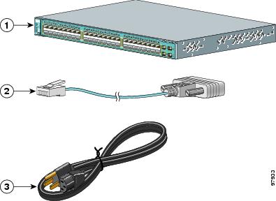
Remove these items from the shipping container:
Figure D-1 The Catalyst 3560 Switch, Adapter Cable, and AC Power Cord
|
|
Catalyst 3560 switch |
|
AC power cord |
|
|
RJ-45-to-DB-9 adapter cable |
Step 2 ![]() Use the supplied RJ-45-to-DB-9 adapter cable to insert the RJ-45 connector into the console port on the switch rear panel, as shown in Figure D-2.
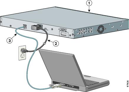
Use the supplied RJ-45-to-DB-9 adapter cable to insert the RJ-45 connector into the console port on the switch rear panel, as shown in Figure D-2.
Figure D-2 Connecting a Switch to a PC
Step 3 ![]() Attach the DB-9 female DTE of the adapter cable to a PC serial port, or attach an appropriate adapter to the terminal.
Attach the DB-9 female DTE of the adapter cable to a PC serial port, or attach an appropriate adapter to the terminal.
Step 4 ![]() Wait before you power on the switch.
Wait before you power on the switch.
|
|
Catalyst 3560 switch |
|
RJ-45-to-DB-9 adapter cable |
|
|
Power cord |
Step 5 ![]() Before you power on the switch, start the terminal emulation session to see the output from the power-on self-test (POST). The terminal-emulation software—frequently a PC application such as Hyperterminal or ProcommPlus—makes communication between the switch and your PC or terminal possible.
Before you power on the switch, start the terminal emulation session to see the output from the power-on self-test (POST). The terminal-emulation software—frequently a PC application such as Hyperterminal or ProcommPlus—makes communication between the switch and your PC or terminal possible.
Step 6 ![]() Configure the baud rate and character format of the PC or terminal to match these console port default characteristics:
Configure the baud rate and character format of the PC or terminal to match these console port default characteristics:
•![]() 9600 baud
9600 baud
•![]() 8 data bits
8 data bits
•![]() 1 stop bit
1 stop bit
•![]() No parity
No parity
•![]() None (flow control)
None (flow control)
Step 7 ![]() Connect one end of the supplied AC power cord to the power connector on a switch rear panel. See Figure D-2.
Connect one end of the supplied AC power cord to the power connector on a switch rear panel. See Figure D-2.
Step 8 ![]() Connect the other end of the power cable to a grounded AC outlet.
Connect the other end of the power cable to a grounded AC outlet.
When the switch powers on, it automatically begins the power-on self test (POST), a series of tests that verifies that the switch functions properly. When the switch begins POST, the system LED slowly blinks green. When POST completes, the system LED blinks amber. If POST fails, the system LED remains amber. If POST completes successfully, the system LED rapidly blinks green.
POST failures are usually fatal. Call Cisco technical support representative if your switch fails POST.
If you started the terminal emulation program before you powered on your switch, the PC or terminal displays the bootloader sequence. You need to press Enter to display the setup program prompt.

Note ![]() If you are connecting the switch to a Cisco redundant power system (RPS), see the documentation that shipped with your RPS.
If you are connecting the switch to a Cisco redundant power system (RPS), see the documentation that shipped with your RPS.
Completing the Setup Program
The setup program runs automatically after the switch powers on. Have this information:
•![]() Switch IP address
Switch IP address
•![]() Subnet mask (IP netmask)
Subnet mask (IP netmask)
•![]() Default gateway (router)
Default gateway (router)
•![]() Enable secret password
Enable secret password
•![]() Enable password
Enable password
•![]() Telnet password
Telnet password
Step 1 ![]() Enter Yes at these two prompts.
Enter Yes at these two prompts.
Would you like to enter the initial configuration dialog? [yes/no]: yes
At any point you may enter a question mark '?' for help.
Use ctrl-c to abort configuration dialog at any prompt.
Default settings are in square brackets '[]'.
Basic management setup configures only enough connectivity
for management of the system, extended setup will ask you
to configure each interface on the system.
Would you like to enter basic management setup? [yes/no]: yes
Step 2 ![]() Enter a host name for the switch, and press Return.
Enter a host name for the switch, and press Return.
On a command switch, the host name is limited to 28 characters; on a member switch to 31 characters. Do not use -n, where n is a number, as the last character in a host name for any switch.
Enter host name [Switch]: host_name
Step 3 ![]() Enter an enable secret password, and press Return.
Enter an enable secret password, and press Return.
The password can be from 1 to 25 alphanumeric characters, can start with a number, is case sensitive, allows spaces, but ignores leading spaces. The secret password is encrypted and the enable password is in plain text.
Enter enable secret: secret_password
Step 4 ![]() Enter an enable password, and press Return.
Enter an enable password, and press Return.
Enter enable password: enable_password
Step 5 ![]() Enter a virtual terminal (Telnet) password, and press Return.
Enter a virtual terminal (Telnet) password, and press Return.
The password can be from 1 to 25 alphanumeric characters, is case sensitive, allows spaces, but ignores leading spaces.
Enter virtual terminal password: terminal-password
Step 6 ![]() (Optional) Configure Simple Network Management Protocol (SNMP) by responding to the prompts. You can also configure SNMP later through the CLI, CMS, or Network Assistant interface. To configure SNMP later, enter no.
(Optional) Configure Simple Network Management Protocol (SNMP) by responding to the prompts. You can also configure SNMP later through the CLI, CMS, or Network Assistant interface. To configure SNMP later, enter no.
Configure SNMP Network Management? [no]: no
Step 7 ![]() Enter the interface name (physical interface or VLAN name) of the interface that connects to the management network, and press Return. For this release, always use vlan1 as that interface.
Enter the interface name (physical interface or VLAN name) of the interface that connects to the management network, and press Return. For this release, always use vlan1 as that interface.
Enter interface name used to connect to the
management network from the above interface summary: vlan1
Step 8 ![]() Configure the interface by entering the switch IP address and subnet mask and pressing Return. The IP address and subnet masks shown are examples.
Configure the interface by entering the switch IP address and subnet mask and pressing Return. The IP address and subnet masks shown are examples.
Configuring interface vlan1:
Configure IP on this interface? [yes]: yes
IP address for this interface: 10.4.120.106
Subnet mask for this interface [255.0.0.0]: 255.0.0.0
Step 9 ![]() Enter Y to configure the switch as the cluster command switch. Enter N to configure it as a member switch or as a standalone switch.
Enter Y to configure the switch as the cluster command switch. Enter N to configure it as a member switch or as a standalone switch.
If you enter N, the switch appears as a candidate switch in the CMS or Network Assistant. You can configure the switch as a command switch later through the CLI, CMS, or Network Assistant interface. To configure it later, enter no.
Would you like to enable as a cluster command switch? [yes/no]: no
You have now completed the initial configuration of the switch, and the switch displays its initial configuration. This is an example of output that appears:
The following configuration command script was created:
hostname switch1
enable secret 5 $1$Ulq8$DlA/OiaEbl90WcBPd9cOn1
enable password enable_password
line vty 0 15
password terminal-password
no snmp-server
!
no ip routing
!
interface Vlan1
no shutdown
ip address 10.4.120.106 255.0.0.0
!
interface FastEthernet1/0/1
!
interface FastEthernet1/0/2
interface FastEthernet1/0/3
!
...<output abbreviated>
!
interface GigabitEthernet2/0/28
!
end
Step 10 ![]() These choices appear:
These choices appear:
[0] Go to the IOS command prompt without saving this config.
[1] Return back to the setup without saving this config.
[2] Save this configuration to nvram and exit.
If you want to save the configuration and use it the next time the switch reboots, save it
in NVRAM by selecting option 2.
Enter your selection [2]:2
Make your selection, and press Return.
After you complete the setup program, the switch can run the default configuration that you created. If you want to change this configuration or want to perform other management tasks, use one of these tools:
•![]() Command-line interface (CLI)
Command-line interface (CLI)
•![]() CMS from your browser
CMS from your browser
•![]() Network Assistant from your browser
Network Assistant from your browser
To use the CLI, enter commands at the Switch> prompt through the console port by using a terminal emulation program or through the network by using Telnet. For configuration information, see the switch software configuration guide or the switch command reference.
To use CMS, see the CMS online help. To use Network Assistant, see the Getting Started with Cisco Network Assistant guide.
For installation procedures for mounting your switch, connecting to the switch ports, or connecting to the small form-factor pluggable (SFP) modules, see Chapter 2 "Switch Installation (24- and 48-Port Switches)" and Chapter 3 "Switch Installation (8- and 12-Port Switches)."
 Feedback