Product Overview
The Catalyst 3560 switch—also referred to as the switch—is an Ethernet switch to which you can connect devices like workstations, Cisco Wireless Access Points, Cisco IP Phones, and other network devices such as servers, routers, and other switches. This chapter provides a functional overview of the Catalyst 3560 switch. These topics are included:
Setting Up the Switch
See the Catalyst 3560 Switch Getting Started Guide for instructions on how to use Express Setup to initially configure your Catalyst switch. The getting started guide provides switch management options, basic rack-mounting procedures, port and module connections, power connection procedures, and troubleshooting help.
For instructions on setting up your switch using the command-line interface (CLI), see "Configuring the Switch with the CLI-Based Setup Program."
Features
The 24- and 48-port Catalyst 3560 switches can be deployed as backbone switches, aggregating 10BASE-T and 100BASE-TX Ethernet traffic from other network devices. The Catalyst 3560-8PC and the Catalyst 3560-12PC-S compact switches provide the same Power over Ethernet (PoE) connectivity and can be deployed outside the traditional wiring closet environment, such as in office workspaces and classrooms. The switches are hot-swappable. See the switch software configuration guide for examples of how you might deploy the switch.
For power redundancy, all but the Catalyst 3560 8- and 12-port switches include connections for an optional Cisco RPS 2300 or Cisco RPS 675 that operates on AC power and supplies backup DC power to the switches.
|
|
|
|---|---|
|
|
|
Catalyst 3560-24PS |
24 10/100 Power over Ethernet (PoE) ports and 2 small form-factor pluggable (SFP) module slots |
Catalyst 3560-24TS-S |
24 10/100 ports and 2 SFP module slots |
Catalyst 3560-48PS |
48 10/100 PoE ports and 4 SFP module slots |
Catalyst 3560-48TS-S |
48 10/100 ports and 4 SFP module slots |
Catalyst 3560V2-24PS |
24 10/100 PoE ports and 2 SFP module slots |
Catalyst 3560V2-24TS |
24 10/100 ports and 2 SFP module slots |
Catalyst 3560V2-48PS |
48 10/100 PoE ports and 4 SFP module slots |
Catalyst 3560V2-48TS |
48 10/100 ports and 4 SFP module slots |
Catalyst 3560V2-24TS-SD |
24 10/100 PoE ports and 2 SFP module slots (DC power) |
Catalyst 3560-8PC1 |
8 10/100 PoE ports and 1 dual-purpose port (one 10/100/1000BASE-T copper port and one SFP module slot) |
Catalyst 3560-12PC-S1 |
12 10/100 PoE ports and 1 dual-purpose port |
|
|
|
Catalyst 3560G-24PS |
24 10/100/1000 PoE ports and 4 SFP module slots |
Catalyst 3560G-24TS |
24 10/100/1000 ports and 4 SFP module slots |
Catalyst 3560G-48PS |
48 10/100/1000 PoE ports and 4 SFP module slots |
Catalyst 3560G-48TS |
48 10/100/1000 ports and 4 SFP module slots |
1 The Catalyst 3560-8PC and the Catalyst 3560-12PC-S switches are smaller than the other Catalyst 3560 switches. They can be mounted with a magnet, have security lock slots, and do not have a fan or an RPS port. |
Supported SFP modules:
•![]() 100BASE-BX10 (only Catalyst 3560 8- and 12-port switches)
100BASE-BX10 (only Catalyst 3560 8- and 12-port switches)
•![]() 100BASE-FX
100BASE-FX
•![]() 100BASE-LX (only Catalyst 3560 8- and 12-port switches)
100BASE-LX (only Catalyst 3560 8- and 12-port switches)
•![]() 1000BASE-BX10
1000BASE-BX10
•![]() 1000BASE-LX
1000BASE-LX
•![]() 1000BASE-SX
1000BASE-SX
•![]() 1000BASE-T (only Catalyst 3560 24- and 48-port switches)
1000BASE-T (only Catalyst 3560 24- and 48-port switches)
•![]() 1000BASE-ZX
1000BASE-ZX
•![]() Coarse Wavelength-Division Multiplexing (CWDM)
Coarse Wavelength-Division Multiplexing (CWDM)
•![]() SFP module patch cable. (CAB-SFP-50CM=.) Switches running Cisco IOS Release 12.2(25)SEB or later support this patch cable.
SFP module patch cable. (CAB-SFP-50CM=.) Switches running Cisco IOS Release 12.2(25)SEB or later support this patch cable.
Configuration:
•![]() For 10/100 and 10/100/1000 ports, the speed and duplex settings are autonegotiated.
For 10/100 and 10/100/1000 ports, the speed and duplex settings are autonegotiated.
•![]() For 10/100 and 10/100/1000 ports, PoE settings are autonegotiated.
For 10/100 and 10/100/1000 ports, PoE settings are autonegotiated.
•![]() For 1000BASE-T SFP module ports, the speed and duplex settings are autonegotiated.
For 1000BASE-T SFP module ports, the speed and duplex settings are autonegotiated.
Front Panel Description
•![]() Fast Ethernet Switch Front Panel Descriptions
Fast Ethernet Switch Front Panel Descriptions
•![]() Gigabit Ethernet Switch Front Panel Descriptions
Gigabit Ethernet Switch Front Panel Descriptions
•![]() LEDs
LEDs
Fast Ethernet Switch Front Panel Descriptions
•![]() Catalyst 3560-24PS and 3560V2-24PS Switch Front Panel, Figure 1-1
Catalyst 3560-24PS and 3560V2-24PS Switch Front Panel, Figure 1-1
•![]() Catalyst 3560-24TS-S, 3560V2-24TS, and 3560V2-24TS-SD Switch Front Panel, Figure 1-2
Catalyst 3560-24TS-S, 3560V2-24TS, and 3560V2-24TS-SD Switch Front Panel, Figure 1-2
•![]() Catalyst 3560-48PS and 3560V2-48PS Switch Front Panel, Figure 1-3
Catalyst 3560-48PS and 3560V2-48PS Switch Front Panel, Figure 1-3
•![]() Catalyst 3560-48TS-S and 3560V2-48TS Switch Front Panel, Figure 1-4
Catalyst 3560-48TS-S and 3560V2-48TS Switch Front Panel, Figure 1-4
•![]() Catalyst 3560-8PC Switch Front Panel, Figure 1-5
Catalyst 3560-8PC Switch Front Panel, Figure 1-5
•![]() Catalyst 3560-12PC-S Switch Front Panel, Figure 1-6
Catalyst 3560-12PC-S Switch Front Panel, Figure 1-6
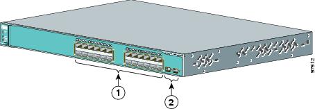
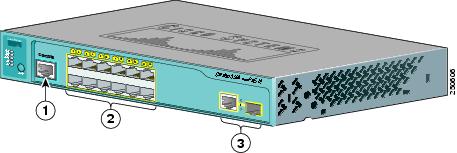
The 10/100 PoE ports on the switch are grouped in pairs. The first member of the pair (port 1) is above the second member (port 2) on the left, as shown in Figure 1-1. Port 3 is above port 4, and so on. The SFP module slots are numbered 1 and 2.
Figure 1-1 Catalyst 3560-24PS and 3560V2-24PS Switch Front Panel
|
|
10/100 PoE ports |
|
SFP module slots |
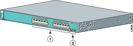
The 10/100 ports on the switch are grouped in pairs. The first member of the pair (port 1) is above the second member (port 2) on the left, as shown in Figure 1-2. Port 3 is above port 4, and so on. The SFP module slots are numbered 1 and 2.
Figure 1-2 Catalyst 3560-24TS-S, 3560V2-24TS, and 3560V2-24TS-SD Switch Front Panel
|
|
10/100 ports |
|
SFP module slots |
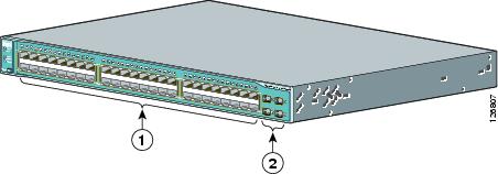
The 10/100 PoE ports on the switch are grouped in pairs. The first member of the pair (port 1) is above the second member (port 2) on the left, as shown in Figure 1-3. Port 3 is above port 4, and so on. The SFP module slots are numbered 1 to 4.
Figure 1-3 Catalyst 3560-48PS and 3560V2-48PS Switch Front Panel

|
|
10/100 PoE ports |
|
SFP module slots |
The 10/100 ports on the switch are grouped in pairs. The first member of the pair (port 1) is above the second member (port 2) on the left, as shown in Figure 1-4. Port 3 is above port 4, and so on. The SFP module slots are numbered 1 to 4.
Figure 1-4 Catalyst 3560-48TS-S and 3560V2-48TS Switch Front Panel
|
|
10/100 ports |
|
SFP module slots |
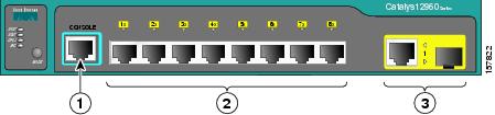
The console port, 10/100 PoE ports, and a dual-purpose port are on the front panel of the Catalyst 3560-8PC switch and the Catalyst 3560-12PC-S switch (Figure 1-5 and Figure 1-6). The dual-purpose port can use either an RJ-45 connector or an SFP module, but not both at the same time.
For more information on the dual-purpose port, see the "Dual-Purpose Port" section. For more information on the console port, see the "Console Port" section.
Figure 1-5 Catalyst 3560-8PC Switch Front Panel
|
|
Console port |
|
Dual-purpose port |
|
|
10/100 PoE ports |
Figure 1-6 Catalyst 3560-12PC-S Switch Front Panel
|
|
Console port |
|
Dual-purpose port |
|
|
10/100 PoE ports |
Gigabit Ethernet Switch Front Panel Descriptions
•![]() Catalyst 3560G-24PS Switch Front Panel, Figure 1-7
Catalyst 3560G-24PS Switch Front Panel, Figure 1-7
•![]() Catalyst 3560G-24TS Switch Front Panel, Figure 1-8
Catalyst 3560G-24TS Switch Front Panel, Figure 1-8
•![]() Catalyst 3560G-48PS Switch Front Panel, Figure 1-9
Catalyst 3560G-48PS Switch Front Panel, Figure 1-9
•![]() Catalyst 3560G-48TS Switch Front Panel, Figure 1-10
Catalyst 3560G-48TS Switch Front Panel, Figure 1-10
The 10/100/1000 PoE ports on the Catalyst 3560G-24PS switch are grouped in pairs. The first member of the pair (port 1) is above the second member (port 2) on the left, as shown in Figure 1-7. Port 3 is above port 4, and so on. The SFP module slots are numbered 25 to 28.
Figure 1-7 Catalyst 3560G-24PS Switch Front Panel

|
|
10/100/1000 ports |
|
SFP module slots |
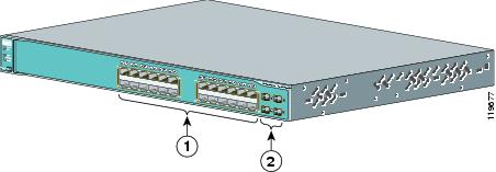
The 10/100/1000 ports on the Catalyst 3560-24TS switch are grouped in pairs. The first member of the pair (port 1) is above the second member (port 2) on the left, as shown in Figure 1-8. Port 3 is above port 4, and so on. The SFP module slots are numbered 25 to 28.
Figure 1-8 Catalyst 3560G-24TS Switch Front Panel
|
|
10/100/1000 ports |
|
SFP module slots |
The 10/100/1000 PoE ports on the Catalyst 3560G-48PS switch are grouped in pairs. The first member of the pair (port 1) is above the second member (port 2) on the left, as shown in Figure 1-9. Port 3 is above port 4, and so on. The SFP module slots are numbered 49 to 52.
Figure 1-9 Catalyst 3560G-48PS Switch Front Panel
|
|
10/100/1000 ports |
|
SFP module slots |
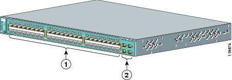
The 10/100/1000 ports on the Catalyst 3560G-48TS switch are grouped in pairs. The first member of the pair (port 1) is above the second member (port 2) on the left, as shown in Figure 1-10. Port 3 is above port 4, and so on. The SFP module slots are numbered 49 to 52.
Figure 1-10 Catalyst 3560G-48TS Switch Front Panel

|
|
10/100/1000 ports |
|
SFP module slots |
10/100 and 10/100/1000 Ports
•![]() You can set the 10/100 ports to operate in any combination of half duplex, full duplex, 10 Mb/s, or 100 Mb/s. You can set the 10/100/1000 ports to operate at 10 or 100 Mb/s in half or full duplex or at 1000 Mb/s in full duplex.
You can set the 10/100 ports to operate in any combination of half duplex, full duplex, 10 Mb/s, or 100 Mb/s. You can set the 10/100/1000 ports to operate at 10 or 100 Mb/s in half or full duplex or at 1000 Mb/s in full duplex.
•![]() You can set both the 10/100 and the 10/100/1000 ports for speed and duplex autonegotiation, in compliance with IEEE 802.3ab. (The default setting is autonegotiate.)
You can set both the 10/100 and the 10/100/1000 ports for speed and duplex autonegotiation, in compliance with IEEE 802.3ab. (The default setting is autonegotiate.)
•![]() You can configure duplex mode to half, full, or autonegotiate on Gigabit Ethernet interfaces if the speed is set to 10 or 100 Mb/s. You cannot configure half-duplex mode on Gigabit Ethernet interfaces if the interface speed is 1000 Mb/s.
You can configure duplex mode to half, full, or autonegotiate on Gigabit Ethernet interfaces if the speed is set to 10 or 100 Mb/s. You cannot configure half-duplex mode on Gigabit Ethernet interfaces if the interface speed is 1000 Mb/s.
•![]() When set for autonegotiation, the port senses the speed and duplex settings of the attached device and advertises its own capabilities. If the connected device also supports autonegotiation, the switch port negotiates the best connection (the fastest line speed that both devices support and full-duplex transmission if the attached device supports it) and configures itself accordingly. In all cases, the attached device must be within 328 feet (100 meters).
When set for autonegotiation, the port senses the speed and duplex settings of the attached device and advertises its own capabilities. If the connected device also supports autonegotiation, the switch port negotiates the best connection (the fastest line speed that both devices support and full-duplex transmission if the attached device supports it) and configures itself accordingly. In all cases, the attached device must be within 328 feet (100 meters).

•![]() 100BASE-TX and 1000BASE-T traffic requires Category 5 cable. 10BASE-T traffic can use Category 3 or Category 4 cables.
100BASE-TX and 1000BASE-T traffic requires Category 5 cable. 10BASE-T traffic can use Category 3 or Category 4 cables.
•![]() When you connect the switch to workstations, servers, routers, and Cisco IP Phones, be sure that the cable is a straight-through cable. When you connect the switch to switches or hubs, use a crossover cable. When using a straight-through or crossover cable for 1000BASE-T connections, be sure to use a twisted four-pair, Category 5 cable for proper operation. Pinouts for the cables are described in "Connector and Cable Specifications."
When you connect the switch to workstations, servers, routers, and Cisco IP Phones, be sure that the cable is a straight-through cable. When you connect the switch to switches or hubs, use a crossover cable. When using a straight-through or crossover cable for 1000BASE-T connections, be sure to use a twisted four-pair, Category 5 cable for proper operation. Pinouts for the cables are described in "Connector and Cable Specifications."
•![]() You can use the mdix auto interface configuration command to enable the automatic medium-dependent interface crossover (auto-MDIX) feature. When the feature is enabled, the switch detects the required cable type for copper Ethernet connections and configures the interfaces accordingly. Therefore, you can use either a crossover or a straight-through cable for connections to a copper 10/100, 10/100/1000, or 1000BASE-T SFP module port on the switch, regardless of the type of device on the other end of the connection.
You can use the mdix auto interface configuration command to enable the automatic medium-dependent interface crossover (auto-MDIX) feature. When the feature is enabled, the switch detects the required cable type for copper Ethernet connections and configures the interfaces accordingly. Therefore, you can use either a crossover or a straight-through cable for connections to a copper 10/100, 10/100/1000, or 1000BASE-T SFP module port on the switch, regardless of the type of device on the other end of the connection.
The auto-MDIX feature is enabled by default on switches running Cisco IOS Release 12.2(18)SE or later. For releases between Cisco IOS Release 12.1(14)EA1 and 12.2(18)SE, the auto-MDIX feature is disabled by default. For configuration information for this feature, see the switch software configuration guide or the switch command reference.
PoE Ports
•![]() The10/100 and 10/100/1000 PoE ports on the switch provide PoE support for devices compliant with IEEE 802.3af and Cisco prestandard PoE support for Cisco IP Phones and Cisco Aironet Access Points.
The10/100 and 10/100/1000 PoE ports on the switch provide PoE support for devices compliant with IEEE 802.3af and Cisco prestandard PoE support for Cisco IP Phones and Cisco Aironet Access Points.
•![]() Each of the Catalyst 3560-8PC, 3560-12PC-S, 3560-24PS, and 3560V2-24PS switch 10/100 ports or the Catalyst 3560G-24PS switch 10/100/1000 ports deliver up to 15.4 W of PoE.
Each of the Catalyst 3560-8PC, 3560-12PC-S, 3560-24PS, and 3560V2-24PS switch 10/100 ports or the Catalyst 3560G-24PS switch 10/100/1000 ports deliver up to 15.4 W of PoE.
On the Catalyst 3560-48PS, 3560G-48PS, and 3560V2-48PS switches, any 24 of the 48 10/100 or 10/100/1000 ports delivers 15.4 W of PoE, or any combination of the ports delivers an average of 7.7 W of PoE at the same time, up to a maximum power output of 370 W.
The Catalyst 3560-12PC-S switch delivers a maximum power output of approximately 125 W total PoE power.
•![]() On a per-port basis, you can control whether or not a PoE port automatically provides power when an IP phone or an access point is connected. The device manager, Network Assistant, and the CLI provide PoE settings for each 10/100 or 10/100/1000 PoE port:
On a per-port basis, you can control whether or not a PoE port automatically provides power when an IP phone or an access point is connected. The device manager, Network Assistant, and the CLI provide PoE settings for each 10/100 or 10/100/1000 PoE port:
–![]() Auto: When you select the Auto setting, the port provides power only if a valid powered device, such as an IEEE 802.3af-compliant powered device, a Cisco prestandard IP phone, or a Cisco prestandard Cisco access point, is connected. The Auto setting is the default.
Auto: When you select the Auto setting, the port provides power only if a valid powered device, such as an IEEE 802.3af-compliant powered device, a Cisco prestandard IP phone, or a Cisco prestandard Cisco access point, is connected. The Auto setting is the default.
–![]() Never: When you select the Never setting, the port does not provide power even if a Cisco IP phone or an access point is connected.
Never: When you select the Never setting, the port does not provide power even if a Cisco IP phone or an access point is connected.
•![]() You can connect a Cisco IP Phone or Cisco Aironet Access Point to a Catalyst 3560 PoE switch 10/100 or 10/100/1000 port and to an AC power source for redundant power. The powered device might change to the AC power source as its primary power source when connected to it. In that case, the PoE port becomes the backup power source for the powered device.
You can connect a Cisco IP Phone or Cisco Aironet Access Point to a Catalyst 3560 PoE switch 10/100 or 10/100/1000 port and to an AC power source for redundant power. The powered device might change to the AC power source as its primary power source when connected to it. In that case, the PoE port becomes the backup power source for the powered device.
If the primary source fails, the second power source becomes the primary power source to the powered device. During the power transfer, an IP phone might reboot or reestablish link with the switch.
For information about configuring and monitoring PoE ports, see the switch software configuration guide. For information about Cisco IP Phones and Cisco Aironet Access Points, see the documentation that came with your IP phone or access point.
Many legacy powered devices, including older Cisco IP phones and access points that do not fully support IEEE 802.3af, might not support PoE when connected to the switches by a crossover cable.
SFP Module Slots
See the release notes for the latest list of supported SFP modules.
SFP Modules
The switch uses Gigabit Ethernet SFP modules to establish fiber-optic and 1000BASE-T connections. These transceiver modules are field-replaceable, providing uplink interfaces when inserted in an SFP module slot. Use fiber-optic cables with LC or MT-RJ connectors to connect to a fiber-optic SFP module. Use a Category 5 cable with RJ-45 connectors to connect to a copper SFP module.
For more information about SFP modules, see your SFP module documentation or the release note for your switch software.
SFP Module Patch Cable
The switch supports the SFP module patch cable (CAB-SFP-50CM=), a 0.5 meter, copper, passive cable with SFP module connectors at each end (see Figure 1-11).
Figure 1-11 SFP Module Patch Cable
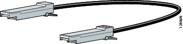
The SFP module patch cable can connect only two Catalyst 3560 switches. To connect a Catalyst 3560 switch to other Catalyst series switches, you must use the SFP modules specified in the "SFP Module Cable Specifications" section.
See "Inserting and Removing the SFP Module Patch Cable" section for more information about using the SFP module patch cable.
Dual-Purpose Port
You can configure a dual-purpose port as either a 10/100/1000 port or as an SFP module port. Each port is considered as a single interface with dual front ends—an RJ-45 connector and an SFP module connector. The dual front ends are not redundant interfaces. The switch activates only one connector of the pair at a time.
By default, the switch dynamically selects the interface type that first links up. However, you can use the media-type interface configuration command to select the RJ-45 connector or the SFP module connector. For information about configuring speed and duplex settings for a dual-purpose uplink, see the software configuration guide.
Each uplink port has two LEDs. One shows the status of the RJ-45 port, and one shows the status of the SFP module port. The port LED is on for the active connector.
LEDs
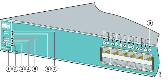
You can use the switch LEDs to monitor switch activity and its performance. Figure 1-12 shows the switch LEDs and the Mode button that you use to select one of the port modes.
All the LEDs described here are visible in the embedded device manager and Network Assistant GUIs. The switch online help describes how to use the device manager or Network Assistant to configure and monitor individual switches and switch clusters.
Figure 1-12 Catalyst 3560 Switch LEDs
|
|
Mode button |
|
Status LED |
|
|
PoE LED1 |
|
RPS LED2 |
|
|
Speed LED |
|
System LED |
|
|
Duplex LED |
|
Port LEDs |
1 The PoE LED is only on the Catalyst 3560 PoE switches. 2 The Catalyst 3560-8PC and the Catalyst 3560-12PC-S switches do not have an RPS LED. |
System LED
|
|
|
|---|---|
Off |
System is not powered on. |
Green |
System is operating normally. |
Amber |
System is receiving power but is not functioning properly. |
For information on the System LED colors during the power-on self-test (POST), see the "Verifying Switch Operation" section.
RPS LED

Note ![]() The Catalyst 3560-8PC and Catalyst 3560-12PC-S switches do not have an RPS LED.
The Catalyst 3560-8PC and Catalyst 3560-12PC-S switches do not have an RPS LED.
For more information about the Cisco RPS 2300 and the RPS 675, see the Cisco Redundant Power System 2300 Hardware Installation Guide and the Cisco RPS 675 Redundant Power System Hardware Installation Guide.
Port LEDs and Modes
The port LEDs, as a group or individually, display information about the switch and about the individual ports:
|
|
|
|
|---|---|---|
STAT |
Port status |
The port status. This is the default mode. |
DUPLX |
Port duplex mode |
The port duplex mode: full duplex or half duplex. |
SPEED |
Port speed |
The port operating speed: 10, 100, or 10001 Mb/s. |
PoE |
PoE port power |
The PoE status. |
1 When installed in Catalyst 3560 switches, 1000BASE-T SFP modules can operate at 10, 100, or 1000 Mb/s in full-duplex mode or at 10 or 100 Mb/s in half-duplex mode. |
Even if the PoE mode is not selected, the PoE LED shows PoE problems when they are detected. The PoE LED applies only to Catalyst 3560 switches that support PoE.
To select or change a mode, press the Mode button until the desired mode is highlighted. When you change port modes, the meanings of the port LED colors also change. Table 1-6 explains how to interpret the port LED colors in different port modes.
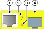
Dual-Purpose Port LEDs
The LEDs on a dual-purpose port (see Figure 1-13) show whether the RJ-45 connector is connected or whether an SFP module is installed. You can configure each port as either a 10/100/1000 port through the RJ-45 connector or as an SFP module, but not both at the same time. The LEDs show how the port is being used.
The LED colors have the same meaning as described in Table 1-4 to Table 1-6.
Figure 1-13 Dual-Purpose Port LEDs
|
|
RJ-45 connector |
|
SFP module port LED |
|
|
RJ-45 port LED |
|
SFP module slot |
Cable Guard
You can order an optional cable guard to secure cables to the front of the switch and prevent them from being accidentally removed. To order a cable guard (CBLGRD-C3560-12PC or CBLGRD-C3560-8PC), contact your Cisco representative. The cable guard serves a different purpose than the cable guide (see "Attaching the Cable Guide" section).
Rear Panel Description
Note ![]() The Catalyst 3560-8PC and the Catalyst 3560-12PC-S switches do not have an RPS connector or a fan. The switch console port is on the front panel.
The Catalyst 3560-8PC and the Catalyst 3560-12PC-S switches do not have an RPS connector or a fan. The switch console port is on the front panel.
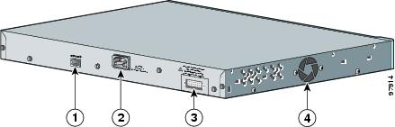
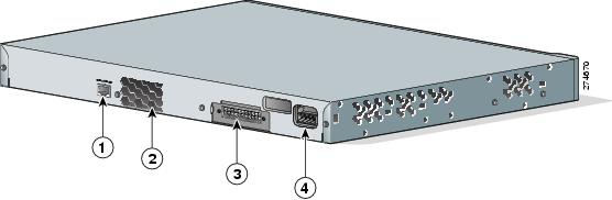
The switch rear panel has an AC power connector, an RPS connector, and an RJ-45 console port. (See Figure 1-14, Figure 1-15, and Figure 1-16 for examples of the Catalyst 3560 rear panels.)
Figure 1-14 Catalyst 3560-24PS and 3560-48PS Switch Rear Panel
|
|
RJ-45 console port |
|
RPS connector |
|
|
AC power connector |
|
Fan exhaust |
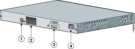
Figure 1-15 Catalyst 3560G-24PS, 3560G-48PS, 3560G-24TS, and 3560G-48TS Switch Rear Panel
|
|
RJ-45 console port |
|
RPS connector |
|
|
Fan exhaust |
|
AC power connector |
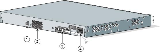
Figure 1-16 Catalyst 3560V2-24PS, 3560V2-48PS, 3560V2-24TS, 3560V2-48TS Switch Rear Panel
|
|
RJ-45 console port |
|
RPS connector |
|
|
Fan exhaust |
|
AC power connector |
Figure 1-17 Catalyst 3560V2-24TS-SD Switch Rear Panel
|
|
RJ-45 console port |
|
RPS connector |
|
|
Fan exhaust |
|
DC power connector |
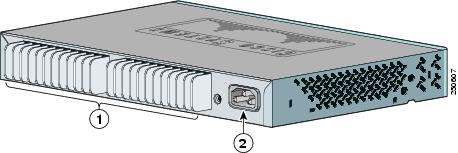
The Catalyst 3560-8PC and Catalyst 3560-12PC-S rear panels have an AC power connector and heat sinks. (See Figure 1-18.)
Figure 1-18 Catalyst 3560-8PC and Catalyst 3560-12PC-S Switch Rear Panel
|
|
Heat sinks |
|
AC power connector |
Internal Power Supply
An internal power supply powers the switch. The internal power supply is an autoranging unit that supports input voltages between 100 and 240 VAC. Use the supplied AC power cord to connect the AC power connector to an AC power outlet.
DC Power Connector
The Catalyst 3560V2-24TS-SD has an internal DC-power converter. It has dual feeds (A and B) that are diode-OR-ed into a single power block. For installation instructions, see "Connecting to DC Power."

Cisco RPS
Depending on the switch model, you can connect the switch to either of these Cisco redundant power systems (RPS) to provide backup power if the switch power supply fails:
Connect the switch and the Cisco RPS to the same AC power source. Use the RPS connector cable supplied with the RPS to connect the RPS to the switch.
Note ![]() When an RPS is connected to the Catalyst 3560V2-24TS-SD switch, the switch is not Network Equipment Building Systems (NEBS) compliant.
When an RPS is connected to the Catalyst 3560V2-24TS-SD switch, the switch is not Network Equipment Building Systems (NEBS) compliant.
Note ![]() The Catalyst 3560-8PC and Catalyst 3560-12PC-S switches do not have an RPS connector.
The Catalyst 3560-8PC and Catalyst 3560-12PC-S switches do not have an RPS connector.
For complete information about the Cisco RPS products, including compatibility matrixes listing the supported RPS for each Catalyst 3560 switch, see the RPS documents on Cisco.com:
http://www.cisco.com/en/US/products/ps7148/prod_installation_guides_list.html
Cisco RPS 2300
The Cisco RPS 2300 is a redundant power system that supports six network switches and provides power to one or two failed switches at a time. It automatically senses when the internal power supply of a connected switch fails and provides power to the failed switch, preventing loss of network traffic.
The Cisco RPS 2300 has two output levels: -52 V and 12 V. The maximum output power depends on the installed power-supply modules.
Cisco RPS 675
The Cisco 675 RPS is a redundant power system that supports six network devices and provides power to one failed switch at a time. It automatically senses when the internal power supply of a connected switch fails and provides power to the failed switch, preventing loss of network traffic.
The Cisco RPS 675 has two output levels: -48 V and 12 V. The maximum output power is 675 W.
Console Port
You can connect the switch to a PC by means of the console port and the supplied RJ-45-to-DB-9 female cable. If you want to connect the switch console port to a terminal, you need to provide an RJ-45-to-DB-25 female DTE adapter. You can order a kit (part number ACS-DSBUASYN=) containing that adapter from Cisco. For console port and adapter pinout information, see the "Connector and Cable Specifications" section.
Security Slots
The Catalyst 3560-8PC and the Catalyst 3560-12PC-S switches have security slots on the left and right side panels. You can install an optional cable lock, such as that used to secure a laptop, to secure either or both sides of the switch.
Figure 1-19 shows the slot on a left-side panel.
Figure 1-19 Switch Left Panel

|
|
Security slot |
Management Options
The Catalyst 3560 switches offer several management options:
•![]() Device manager
Device manager
You can use the device manager in the switch memory to manage individual and standalone switches. Device manager is a web interface that offers quick configuration and monitoring. You can access the device manager from anywhere in your network through a web browser. For more information, see the device manager online help.
•![]() Cisco Network Assistant
Cisco Network Assistant
Cisco Network Assistant is a free software program that you download from Cisco.com and run on your PC. It offers advanced options for configuring and monitoring multiple devices, including switches, switch clusters, switch stacks, routers, and access points.
Follow these steps:
a. ![]() Go to this Web address: http://www.cisco.com/cisco/software/navigator.html?mdfid=279230132&i=rp
Go to this Web address: http://www.cisco.com/cisco/software/navigator.html?mdfid=279230132&i=rp
You must be a registered Cisco.com user, but you need no other access privileges.
b. ![]() Find the Network Assistant installer.
Find the Network Assistant installer.
c. ![]() Download the Network Assistant installer, and run it. (You can run it directly from the web if your browser offers this choice.)
Download the Network Assistant installer, and run it. (You can run it directly from the web if your browser offers this choice.)
d. ![]() When you run the installer, follow the displayed instructions. In the final panel, click Finish to complete the Network Assistant installation.
When you run the installer, follow the displayed instructions. In the final panel, click Finish to complete the Network Assistant installation.
See the Network Assistant online help and the getting started guide for more information.
•![]() Cisco IOS CLI
Cisco IOS CLI
The switch CLI is based on Cisco IOS software and is enhanced to support desktop-switching features. You can fully configure and monitor the switch and switch cluster members from the CLI. You can access the CLI either by connecting your management station directly to the switch console port or by using Telnet from a remote management station. See the Catalyst 3560 Switch Command Reference on Cisco.com for more information.
For setup instructions that use the CLI, go to "Configuring the Switch with the CLI-Based Setup Program."
•![]() CiscoView application
CiscoView application
The CiscoView device-management application displays the switch image that you can use to set configuration parameters and to view switch status and performance information. The CiscoView application, which you purchase separately, can be a standalone application or part of a Simple Network Management Protocol (SNMP) platform. See the CiscoView documentation for more information.
•![]() SNMP network management
SNMP network management
You can manage switches from a SNMP-compatible management station that is running platforms such as HP OpenView or SunNet Manager. The switch supports a comprehensive set of Management Information Base (MIB) extensions and four Remote Monitoring (RMON) groups. See the switch software configuration guide on Cisco.com and the documentation that came with your SNMP application for more information.
Network Configurations
See the switch software configuration guide on Cisco.com for an explanation of network configuration concepts. The software configuration guide also provides examples of network configurations that use the switch to create dedicated network segments that are interconnected through Ethernet connections.
 Feedback