Switch Models
|
Switch Model |
Description |
|---|---|
|
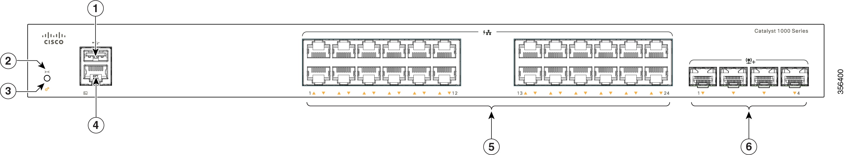
C1000-24T-4G-L |
24 10/100/1000 Ethernet ports; four 1-Gigabit Ethernet small form-factor pluggable (SFP) module uplink slots |
|
C1000-24P-4G-L |
24 10/100/1000 PoE+ ports (PoE budget of 195W); four 1-Gigabit Ethernet SFP module uplink slots |
|
C1000-24FP-4G-L |
24 10/100/1000 PoE+ ports (PoE budget of 370W); four 1-Gigabit Ethernet SFP module uplink slots |
|
C1000-48T-4G-L |
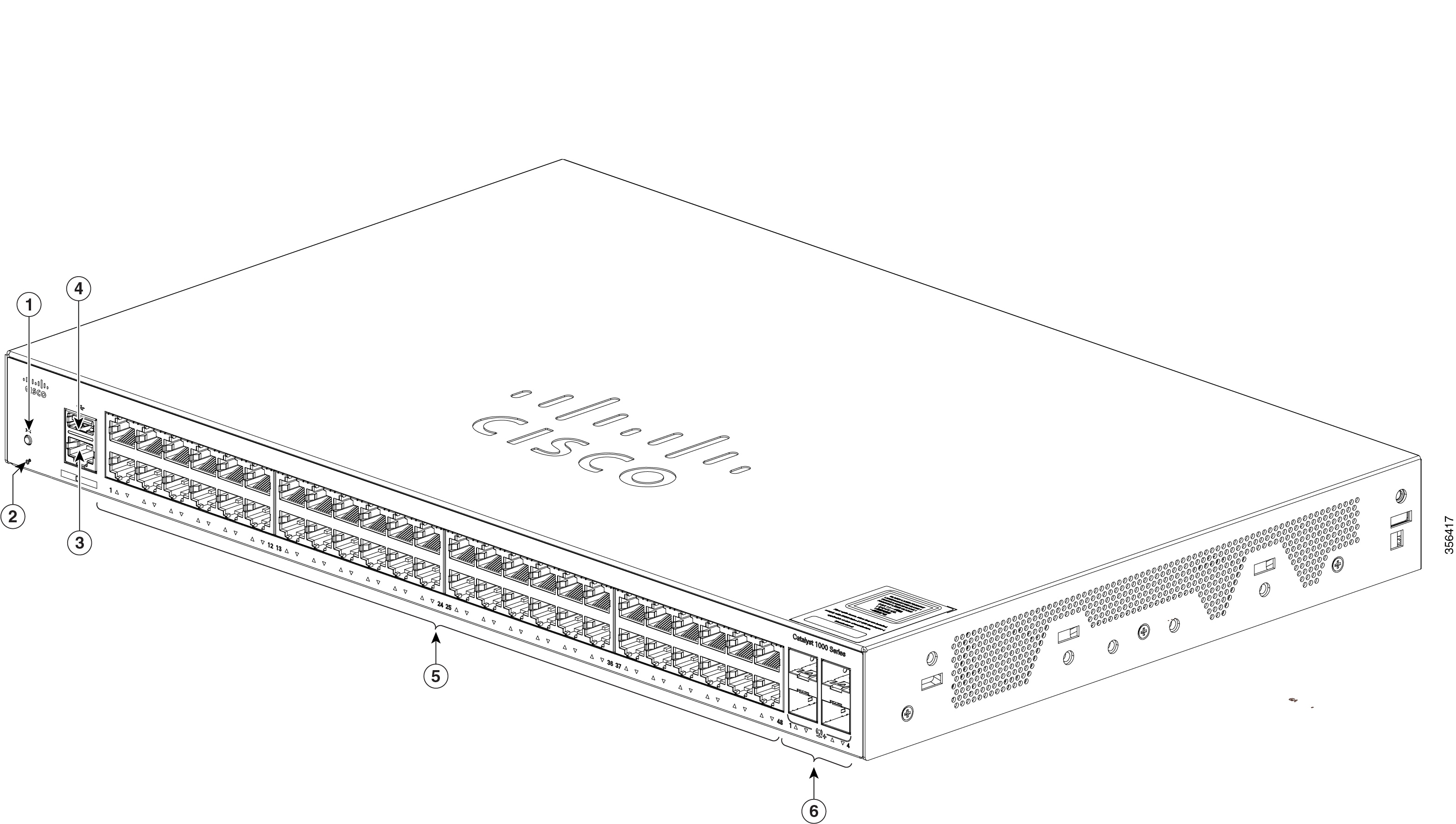
48 10/100/1000 Ethernet ports; four 1-Gigabit Ethernet SFP module uplink slots |
|
C1000-48P-4G-L |
48 ports; 12x10/100/1000 PoE+ ports (PoE budget of 370W) and 36x10/100/1000 Ethernet ports; four 1-Gigabit Ethernet SFP module uplink slots |
|
C1000-48FP-4G-L |
48 10/100/1000 PoE+ ports (PoE budget of 740W); four 1-Gigabit Ethernet SFP module uplink slots |
|
C1000-24T-4X-L |
24 10/100/1000 Ethernet ports; four 10-Gigabit Ethernet small form-factor pluggable plus (SFP+) module uplink slots |
|
C1000-24P-4X-L |
24 10/100/1000 Ethernet ports; limited PoE+ ports (PoE budget of 195W); four 10-Gigabit Ethernet SFP+ module uplink slots |
|
C1000-24FP-4X-L |
24 10/100/1000 PoE+ ports (PoE budget of 370W); four 10-Gigabit Ethernet SFP+ module uplink slots |
|
C1000-48T-4X-L |
48 10/100/1000 Ethernet ports; four 10-Gigabit Ethernet SFP+ module uplink slots |
|
C1000-48P-4X-L |
48 10/100/1000 PoE+ ports (PoE budget of 370W); four 10-Gigabit Ethernet SFP+ module uplink slots |
|
C1000-48FP-4X-L |
48 10/100/1000 PoE+ ports (PoE budget of 740W); four 10-Gigabit Ethernet SFP+ module uplink slots |
|
Switch Model |
Description |
|---|---|
|
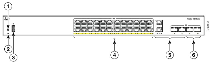
C1000FE-24T-4G-L |
24 10/100 Fast Ethernet ports; 2 1-Gigabit SFP module uplink slots or 2 RJ-45 slots combo ports; 2 1-Gigabit Ethernet SFP module uplink slots. |
|
C1000FE-24P-4G-L |
24 10/100 Fast Ethernet ports (PoE budget of 195W); 2 1-Gigabit SFP module uplink slots or 2 RJ-45 slots combo ports; 2 1-Gigabit Ethernet SFP module uplink slots. |
|
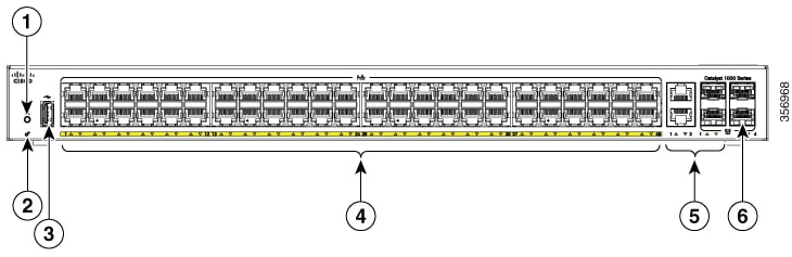
C1000FE-48T-4G-L |
48 10/100 Fast Ethernet ports; 2 1-Gigabit SFP module uplink slots or 2 RJ-45 slots combo ports; 2 1-Gigabit Ethernet SFP module uplink slots. |
|
C1000FE-48P-4G-L |
48 10/100 Fast Ethernet ports (PoE budget of 370W); 2 1-Gigabit SFP module uplink slots or 2 RJ-45 slots combo ports; 2 1-Gigabit Ethernet SFP module uplink slots. |

 Feedback