Safety Warnings
 Warning |
To reduce the risk of electric shock, disconnect all power cords before servicing. |
Warning |
The switch is to be connected only to PoE networks without routing to the outside plant. |
This section includes the warning statements relating to basic installation. Read this section before you start the installation procedure.
Warning |
Before working on equipment that is connected to power lines, remove jewelry (including rings, necklaces, and watches). Metal objects will heat up when connected to power and ground and can cause serious burns or weld the metal object to the terminals. Statement 43 |
Warning |
Do not stack the chassis on any other equipment. If the chassis falls, it can cause severe bodily injury and equipment damage. Statement 48 |
Warning |
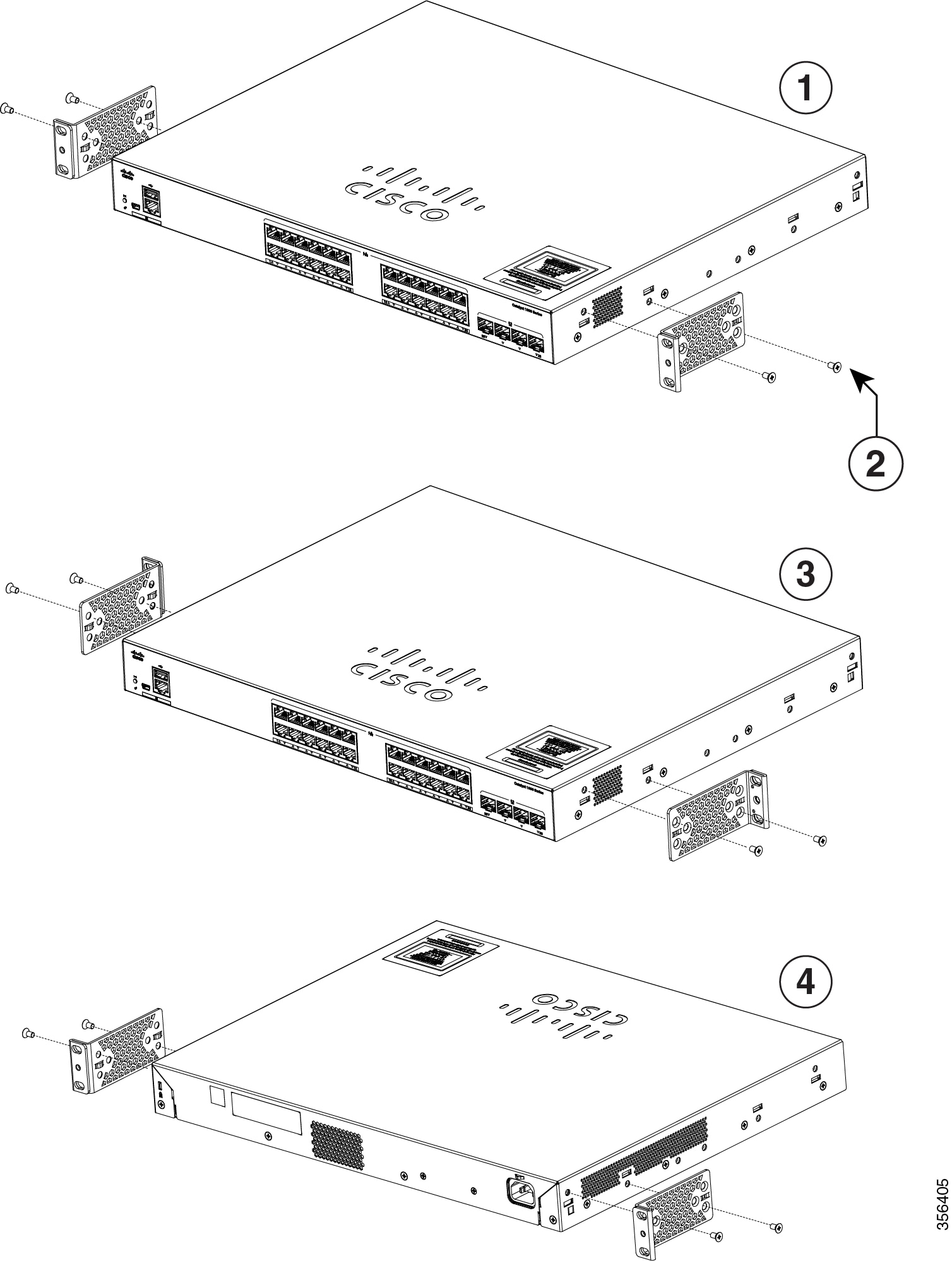
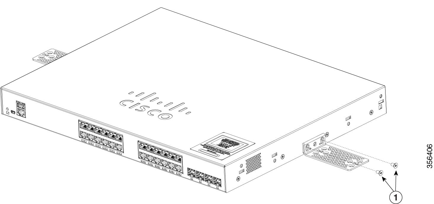
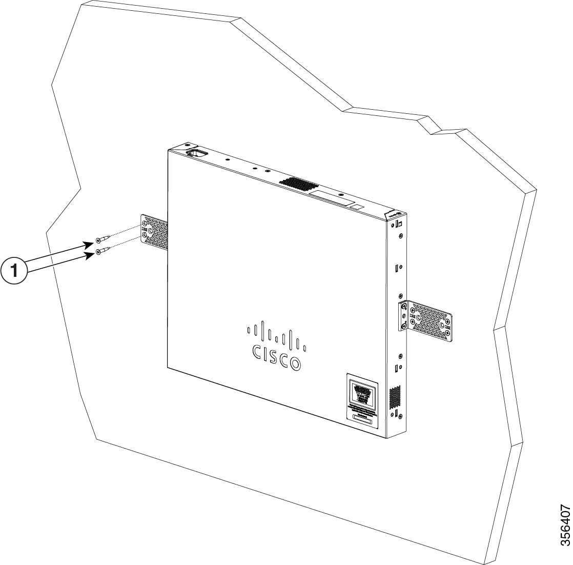
Read the wall-mounting instructions carefully before beginning installation. Failure to use the correct hardware or to follow the correct procedures could result in a hazardous situation to people and damage to the system. Statement 378 |
Warning |
Connect USB Device to a Certified USB Port. Statement 388 |
Warning |
To avoid or reduce the risk of personal injury, do not use the product if the product has been exposed to irregular environmental conditions, if the product has been misused or if parts of the product have been damaged. Consult qualified service personnel. Never try to service the product yourself. Statement 0416 |
Warning |
To reduce the risk of electric shock, fire or personal injury, do not place power cables in areas where they may be walked on or damaged by items placed upon or against it. Statement 0417 |
Warning |
This product is intended for use in a normal environment based on the standard IEC60950-1 and IEC62368-1. Do not use the product in vehicles, on board ships, in aircrafts or in medical applications with physical connection to the patient, nor in environments with exposure to moisture, dust, vibration or ingress of water. Statement 0418 |
Warning |
Equipment is intended for installation in Information Technology Equipment Rooms. Suitable for installation in Information Technology Rooms in accordance with Article 645 of the National ElectricalCode and NFPA 75. Statement 0444 |
Warning |
Do not work on the system or connect or disconnect cables during periods of lightning activity. Statement 1001 |
Warning |
Read the installation instructions before connecting the system to the power source. Statement 1004 |
Warning |
To prevent bodily injury when mounting or servicing this unit in a rack, you must take special precautions to ensure that the system remains stable. The following guidelines are provided to ensure your safety:
Statement 1006 |
Warning |
Class 1 laser product. Statement 1008 |
Warning |
There is the danger of explosion if the battery is replaced incorrectly. Replace the battery only with the same or equivalent type recommended by the manufacturer. Dispose of used batteries according to the manufacturer’s instructions. Statement 1015 |
Warning |
This unit is intended for installation in restricted access areas. A restricted access area can be accessed only through the use of a special tool, lock and key, or other means of security. Statement 1017 |
Warning |
Take care when connecting units to the supply circuit so that wiring is not overloaded. Statement 1018 |
Warning |
The plug-socket combination must be accessible at all times, because it serves as the main disconnecting device. Statement 1019 |
Warning |
This equipment must be grounded. Never defeat the ground conductor or operate the equipment in the absence of a suitably installed ground conductor. Contact the appropriate electrical inspection authority or an electrician if you are uncertain that suitable grounding is available. Statement 1024 |
Warning |
Class 1 LED product. Statement 1027 |
Warning |
Only trained and qualified personnel should be allowed to install, replace, or service this equipment. Statement 1030 |
Warning |
Ultimate disposal of this product should be handled according to all national laws and regulations. Statement 1040 |
Warning |
When installing or replacing the unit, the ground connection must always be made first and disconnected last. Statement 1046 |
Warning |
To prevent the system from overheating, do not operate it in an area that exceeds the maximum recommended ambient temperature of: <122°F (50°C).Statement 1047 |
Warning |
Invisible laser radiation may be emitted from disconnected fibers or connectors. Do not stare into beams or view directly with optical instruments. Statement 1051 |
Warning |
Invisible laser radiation may be emitted from the end of the unterminated fiber cable or connector. Do not view directly with optical instruments. Viewing the laser output with certain optical instruments (for example, eye loupes, magnifiers, and microscopes) within a distance of 100 mm may pose an eye hazard. 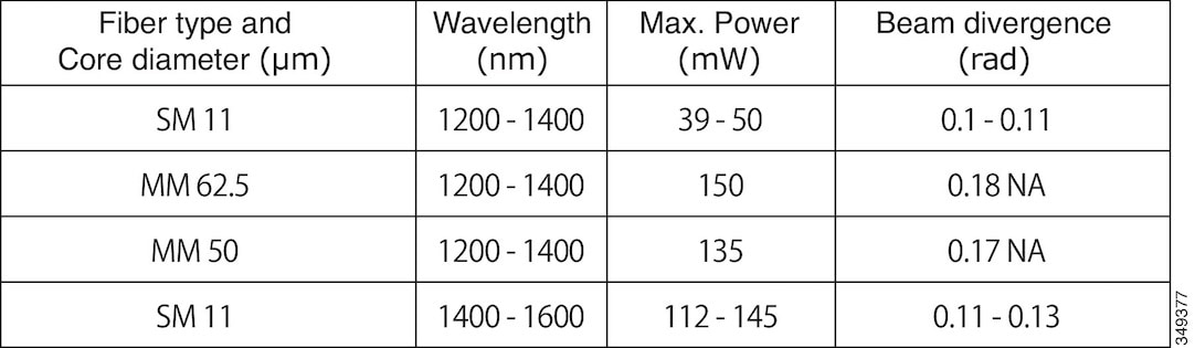 Statement 1056 |
Warning |
This warning symbol means danger. You are in a situation that could cause bodily injury. Before you work on any equipment, be aware of the hazards involved with electrical circuitry and be familiar with standard practices for preventing accidents. Use the statement number provided at the end of each warning to locate its translation in the translated safety warnings that accompanied this device. Statement 1071 |
Warning |
Voltages that present a shock hazard may exist on Power over Ethernet (PoE) circuits if interconnections are made using uninsulated exposed metal contacts, conductors, or terminals. Avoid using such interconnection methods, unless the exposed metal parts are located within a restricted access location and users and service people who are authorized within the restricted access location are made aware of the hazard. A restricted access area can be accessed only through the use of a special tool, lock and key or other means of security. Statement 1072 |
Warning |
No user-serviceable parts inside. Do not open. Statement 1073 |
Warning |
Installation of the equipment must comply with local and national electrical codes. Statement 1074 |
Warning |
To prevent airflow restriction, allow clearance around the ventilation openings to be at least: 3 inches (7.6 cm). Statement 1076 |
Warning |
Hot surface. Statement 1079 |


 Feedback