Overview
This topic explains the hardware specifications and features of the Cisco N9164E-NS4-O switch. It describes how this high-speed device supports AI and machine learning networks using 64 powerful ports, efficient cooling fans, and reliable power supplies.
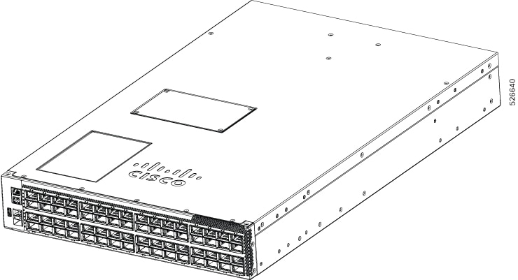
The Cisco N9164E-NS4-O switch is a 2-rack unit (RU), fixed-port high-density switch designed to support high-density, 800G fabrics for next-generation leaf-and-spine designs. This switch contains Nvidia Spectrum 4 to support AI-ready data center deployments. The switch is designed for Ethernet-based artificial intelligence and machine learning (AI/ML), and for web-scale spine deployments. The switch offers full adaptive routing. All ports support MACsec (Media Access Control Security) encryption.
The switch uses a 5 nm process and provides 51.2 terabits per second (Tbps) bandwidth with 512 × 112 Gbps serializer-deserializer (SerDes) channels. This switch has 64 × 800 GbE OSFP (Octal Small Form-Factor Pluggable) ports that provide high-speed connectivity to networking equipment. Each breakout port supports a breakout mode of 2 × 400G. This switch has these ports and capabilites:
-
1 console port,
-
One management port (one RJ-45 port),
-
One USB port, and
-
Two SFP28 25G in-band management ports.
Operating system support
This switch supports only the Cisco NX-OS operating system.
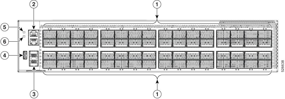
This table lists the components on the front panel of the Cisco N9164E-NS4-O switch.
| Port |
Description |
|---|---|
| 1 |
64 x 800G OSFP ports |
| 2 |
RJ45 ports (2): 1 Console + 1G Management port |
| 3 |
SFP28 x 2 in-band management ports |
| 4 |
USB 3.0 port, Type A |
| 5 |
System LEDs |
| 6 |
Attention (ATTN) LED |
Each OSFP port has its own bi-color (amber or green) LED to indicate link status. For port LED status information, see Switch chassis LEDs.
The maximum power provided to each OSFP port is 18W per instance.
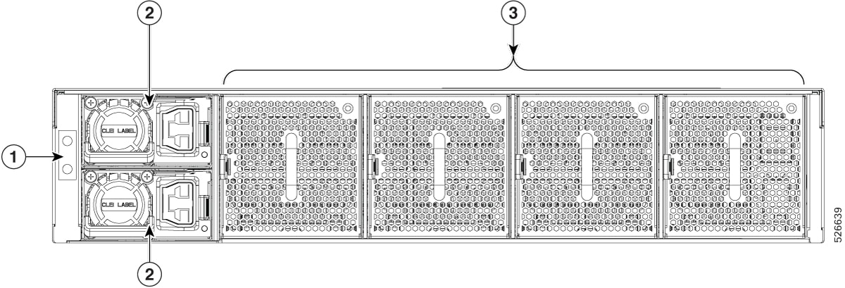
This table lists the components on the rear view of the Cisco N9164E-NS4-O switch with power supplies and fan tray.
| Port |
Description |
|---|---|
| 1 |
Ground lug location |
| 2 |
Power supplies (PSU-1 and PSU-2) |
| 3 |
Fan tray Four fans: FT1, FT2, FT3, and FT4 |
This switch includes these user-replaceable components:
Fan modules (four) with one airflow choice: Port side intake fan module (NXASFAN-190CFMPI).
If more than one fan tray fails, the switch issues a warning and powers down within two minutes unless corrective action is taken to replace the failed fan trays.
The switch has four latched fan modules that install into the chassis from the rear. Fans cool the system and maintain proper airflow through the system. The fan modules work with N+1 redundancy.
The switch supports two power supply modules: one for operations and one for redundancy (1+1). The module can use AC power; the available option is a 3 kilowatt (kW) AC power supply module (PSU3KW-HVPI).
All fan modules and power supplies must use the same airflow direction. For this switch, the airflow direction is front to back.
The figure shows the switch on the port side of the chassis.