Cisco N9164E-NS4-O Hardware Installation Guide

PDF

Install the chassis in a four-post rack

Want to summarize with AI?

Log in

Overview

This topic explains how to prepare for chassis installation by ensuring the rack is securely fastened to the data center floor and reviewing the items included in the rack-mount kit.

Before you install the chassis, be sure that the rack is fully secured to the data center floor.

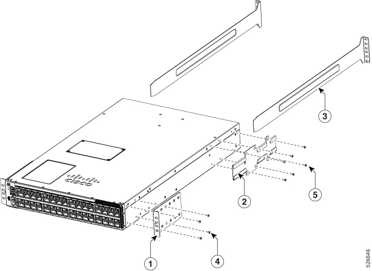
This table lists the items contained in the rack-mount kit.

Table 1. Contents in the rack-mount kit

Quantity

Part Description

2

Rack-mount brackets

2

M4 x 8 mm Phillips pan-head screws

2

Rack-mount guides

2

Rack-mount guide rails

1

Grounding lug and screws

20

M4 x 6 mm Phillips flat-head screws

Note

This switch does not support port-side exhaust configuration.


Rack-mount the chassis in a 4-post rack

Warning

To reduce risk of electric shock or fire, installation of the equipment must comply with local and national electrical codes.

Warning

To prevent personal injury or damage to the chassis, never attempt to lift or tilt the chassis using the handles on modules, such as power supplies, fans, or cards. These types of handles are not designed to support the weight of the unit.

Warning

To prevent bodily injury when mounting or servicing this unit in a rack, you must take special precautions to ensure that the system remains stable. The following guidelines are provided to ensure your safety:

  • This unit should be mounted at the bottom of the rack if it is the only unit in the rack.

  • When mounting this unit in a partially filled rack, load the rack from the bottom to the top with the heaviest component at the bottom of the rack.

  • If the rack is provided with stabilizing devices, install the stabilizers before mounting or servicing the unit in the rack.

Procedure

1.

Install the rack-mount brackets on the switch.

  1. Determine which end of the chassis is to be located in the cold aisle.

    If the switch has port-side intake modules (fan modules and power modules with burgundy coloring), position the switch so that the ports are in the cold aisle.

  2. Position a rack-mount bracket on the side of the chassis with its four holes that are aligned to four of the screw holes on the side of the chassis. Use four M4 flat-head screws with 13.25 in-lb (1.5 N·m) torque value to attach the bracket to the chassis.

    Note
    Align four holes in the rack-mount bracket to four screw holes on the front side of chassis or four screw holes on the rear side of the chassis. The holes that you use depend on which end of your chassis is located in the cold aisle.
    Figure 1. Rack Mount Brackets on Cisco N9164E-NS4-O Switch—Port Side Intake Illustrates the components to rack-mount the chassis in a four-post rack

    This table lists the components required to rack-mount the chassis in a four-post rack.

    Table 2. Components to rack-mount chassis

    Callout

    Description

    1

    Rack-mount brackets

    2

    Rack-mount guides

    3

    Rack-mount guide rails

    4

    M4 x 6 mm Phillips flat-head screw

    5

    M4 x 6 mm Phillips flat-head screw

  3. Repeat Step 1b with the other rack-mount bracket on the other side of the switch.

2.

Install the two rack-mount guides on the chassis.

  1. Position a rack-mount guides on the side of the chassis with its six holes aligned to the six screw holes on the side of the chassis, and use six M4 flat-head screws to attach the guides to the chassis. Tighten the screws to a torque of 13.25 in-lb (1.5 N·m).

  2. Repeat with the other rack-mount guide on the other side of the switch.

3.

Install the guide rails to the rack.

  1. Position the guide rails at the desired levels on the back side of the rack. Use four 12-24 screws or four 10-32 screws, depending on the rack thread type, to attach the rails to the rack.

    Note
    For racks with square holes, you may need to position a 12-24 or 10-32 cage nut behind each mounting hole in a guide rail before using a 12-24 or 10-32 screw.
  2. Repeat with the other guide rail on the opposite side of the rack.

  3. Use a tape measure and a level to verify that the rails are at the same height and are horizontal.

4.

Insert the switch into the rack and attach it.

  1. Use both hands to position the back of the switch between the front posts of the rack.

  2. Align the two rack-mount guides on each side of the switch with the guide rails installed in the rack. Slide the rack-mount guides onto the guide rails. Gently slide the switch all the way into the rack.

    Note
    If the switch does not slide easily, try realigning the rack-mount guides on the guide rails.
  3. While holding the chassis level, insert two screws (12-24 or 10-32, depending on the rack type) through the holes in each rack-mount bracket and into the cage nuts or threaded holes in the rack-mounting rail.

  4. Tighten the 10-32 screws to 20 in-lb (2.26 N·m) or tighten the 12-24 screws to 30 in-lb (3.39 N·m).