Replacing a Power Supply Module
The switch requires two power supplies for redundancy. With one power supply providing the necessary power for operations, replace the other power supply during operations as long as the new power supply has the same airflow direction as the other modules in the chassis.
Replace a power supply with another supported power supply that has the same power source type as the other installed power supply. Additionally, the airflow direction of the power supply must match or conform to the airflow direction of the installed fan modules. For the airflow direction used by the switch, see the coloring of the fan modules.
Replacing an AC Power Supply
Replace an AC power supply during operations as long as the other power supply provides power to the switch.
Before you begin
 Note |
Determine the airflow direction by looking at the coloring of the latch on each power supply. AC power supplies with burgundy latches have port-side intake airflow direction AC power supplies with blue latches have port-side exhaust airflow direction. |
-
An AC power source must be within reach of the power cable that will be used with the replacement power supply. If you are using n+n power redundancy, there must be a separate power source for each power supply installed in the chassis.
-
There must be an earth ground connection to the chassis that you are installing the replacement module. AC power supplies connected to AC power sources are automatically grounded through their power cable.
Procedure
|
Step 1 |
Remove an AC power supply. |
|
Step 2 |
Install the replacement power supply. |
Installing and Removing Small-Form Pluggable Modules
Before you begin
 Warning |
Statement 1008—Class 1 Laser Product This product is a Class 1 laser product. |
Note |
We recommend that you wait 30 seconds between removal and insertion of an SFP on an interface module. This allows the transceiver software to initialize and synchronize with the standby RSP. Changing an SFP more quickly could result in transceiver initialization issues that disable the SFP. |
Note |
QSFP-DD optic (400G/200G) should have a wait time of 2 minutes between removal and reinsertion. |
-
Do not remove the dust plugs from the SFP and SFP+ modules or the rubber caps from the fiber-optic cable until you are ready to connect the cable. The plugs and caps protect the module ports and cables from contamination and ambient light.
-
Removing and installing an SFP and SFP+ module can shorten its useful life. Do not remove and insert any SFP/SFP+ module more often than is necessary.
-
To prevent ESD damage, follow your normal board and component handling procedures when connecting cables to the switch and other devices.
-
When you insert several SFP and SFP+ modules in multiple ports, wait for 5 seconds between inserting each SFP/SFP+. This will prevent the ports from going into error / disabled mode. Similarly, when you remove an SFP and SFP+ from a port, wait for 5 seconds before reinserting it.
SUMMARY STEPS
- Attach an ESD-preventive wrist strap to your wrist and to an earth ground surface.
- Find the send (TX) and receive (RX) markings that identify the top of the SFP/SFP+ module.
- If the SFP/SFP+ module has a bale-clasp latch, move it to the open, unlocked position.
- Align the module in front of the slot opening and push until you feel the connector snap into place.
- If the module has a bale-clasp latch, close it to lock the SFP/SFP+ module in place.
- Remove the SFP and SFP+ dust plugs and save.
- Connect the SFP and SFP+ cables.
DETAILED STEPS
| Command or Action | Purpose | |
|---|---|---|
|
Step 1 |
Attach an ESD-preventive wrist strap to your wrist and to an earth ground surface. |
|
|
Step 2 |
Find the send (TX) and receive (RX) markings that identify the top of the SFP/SFP+ module. |
On some SFP/SFP+ modules, the send and receive (TX and RX) markings might be shown by arrows that show the direction of the connection. |
|
Step 3 |
If the SFP/SFP+ module has a bale-clasp latch, move it to the open, unlocked position. |
|
|
Step 4 |
Align the module in front of the slot opening and push until you feel the connector snap into place. |
|
|
Step 5 |
If the module has a bale-clasp latch, close it to lock the SFP/SFP+ module in place. |
|
|
Step 6 |
Remove the SFP and SFP+ dust plugs and save. |
|
|
Step 7 |
Connect the SFP and SFP+ cables. |
Install and Remove OSFP/QSFP Transceiver Modules
This section provides the installation, cabling, and removal instructions for the Quad Small Form-Factor Pluggable transceiver modules. Refer to the Cisco Transceiver Modules Compatibility Information for additional details on optical transceivers.
Installing the Transceiver Module
Warning |
Statement 1079—Hot Surface This icon is a hot surface warning. To avoid personal injury, do not touch without proper protection.  |
 Caution |
The transceiver module is a static-sensitive device. Always use an ESD wrist strap or similar individual grounding device when handling transceiver modules or coming into contact with system modules. |
Caution |
Protect the transceiver ports by inserting clean dust caps (8000-QSFP-DCAP) into any ports not in use or that do not have optical modules plugged in. If optical modules are plugged in but not in use, use the dust caps that were supplied with the optical modules to protect the TX and RX surfaces of the optical module. Clean the optic surfaces of the fiber cables before you plug them back into the optical ports of another module. The switch ships with dust caps plugged in. We highly recommend you keep the dust caps plugged in until you are ready to plug an optic. The dust caps protect the ports from possible EMI interference and also avoid contamination due to dust collection. |
Caution |
To meet the EMI interference requirements, use the metal dust caps when the ports are not in use by optical modules. |
Before you begin
Required Tools and Equipment
-
Wrist strap or other personal grounding device to prevent ESD occurrences
-
Antistatic mat or antistatic foam to set the transceiver on
-
Fiber-optic end-face cleaning tools and inspection equipment
Procedure
|
Step 1 |
Attach an ESD wrist strap to yourself and a properly grounded point on the chassis or the rack. |
|
Step 2 |
Remove the transceiver module from its protective packaging. |
|
Step 3 |
Check the label on the transceiver module body to verify that you have the correct model for your network. Do not remove the dust plug until you’re ready to attach the network interface cable. The dust plug is not shown in the images. |
|
Step 4 |
Hold the transceiver by the pull-tab so that the identifier label is on the top. |
|
Step 5 |
Align the transceiver module in front of the module’s transceiver socket opening and carefully slide the transceiver into the socket until the transceiver contacts the socket electrical connector. 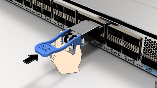
|
|
Step 6 |
Press firmly on the front of the transceiver module with your thumb to fully seat the transceiver in the module’s transceiver socket (see figure Seating the QSFP Transceiver Module). 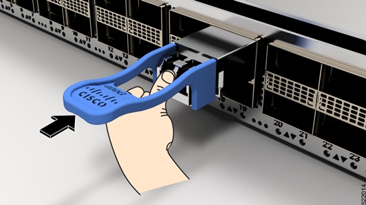
IMPORTANT: If the latch isn’t fully engaged, you might accidentally disconnect the transceiver module. |
 Feedback