Overview
The Cisco Nexus 9348GC-FX3 switch (N9K-C9348GC-FX3) is a 1-rack unit (RU) switch that supports 696 Gbps of bandwidth and over 517 Mpps designed for deployment in data centers. The 48 x 100M/1G BASE-T downlink ports on the 9348GC-FX3 can be configured to work as 100-Mbps or 1-Gbps ports. The 4 x 10/25G SFP28 uplink ports can be configured as 1/10/25-Gbps; the 2 x 40/100G QSFP28 uplink ports can be configured as 40- and 100-Gbps ports. These configuratoin options allow for a combination of 10-, 25-, 40-, and 100-Gbps connectivity, offering flexible migration options for spine-leaf-APIC deployment in data centers.
This switch includes these user-replaceable components:
-
Fan modules (three) with these airflow choices:
-
Port-side intake airflow with burgundy coloring (NXA-SFAN-30CFM-PI)
-
Port-side exhaust airflow with blue coloring (NXA-SFAN-30CFM-PE)

Note
This switch will power down due to a fan-policy trigger if fewer than 2 fans are operational.
Note
Table 1. Fan Speeds for this Switch Port-Side Intake
Fan Speed %
Port-Side Exhaust
Fan Speed %
Typical/Minimum
40%
40%
Maximum
100%
100%
Note
Each fan module has two rotors. The switch can function normally if one rotor inside the any one fan module fails. In case of more than one rotor failure, the switch will issue a warning and power down in 2 minute.
-
-
Power supply modules (two—one for operations and one for redundancy [1+1]) with these choices (a mix of AC and DC power sources is supported but do not mix airflow directions):
-
350-W AC power supply with port-side intake airflow (burgundy coloring) (NXA-PAC-350W-PI2)
-
350-W AC power supply with port-side exhaust airflow (blue coloring) (NXA-PAC-350W-PE2)
-
350-W PHV power supply with port-side intake airflow (burgundy coloring) (NXA-PHV-350W-PI)
-
350-W PHV power supply with port-side exhaust airflow (blue coloring) (NXA-PHV-350W-PE)
-
440-W DC power supply with port-side intake airflow (burgundy coloring) (NXA-PDC-440W-PI)
-
440-W DC power supply with port-side exhaust airflow (blue coloring) (NXA-PDC-440W-PE)
Note
The 350-W AC power supply does not have the standby voltage to be able to carry to a second power supply, to allow it to communicate and poll the device.
-
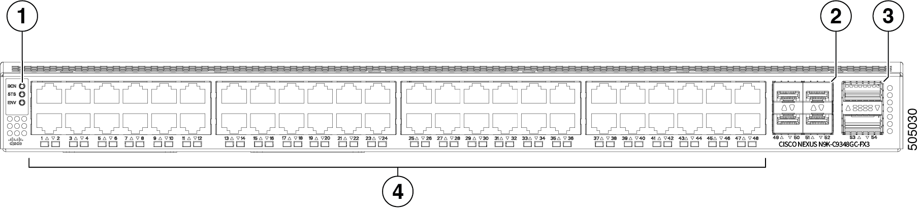
The figure shows the switch features on the port side of the chassis.
|
1 |
LEDs |
2 |
10/25G SFP28 uplink ports (4) |
|
3 |
40/100G QSFP28 uplink ports (2) |
4 |
10M/100M/1G BASE-T downlink ports (48) |
To determine which transceivers, adapters, and cables support this switch, see the Cisco Transceiver Modules Compatibility Information document.
Note |
IMPORTANT: All compatible SFP28 tranceivers identified in the Cisco Optics Interoperability Matrix User Manual can be plugged into any of the SFP28 ports on this switch. All compatible QSFP28 tranceivers identified in the Cisco Optics Interoperability Matrix User Manual can be plugged into any of the QSFP28 ports on this switch. |
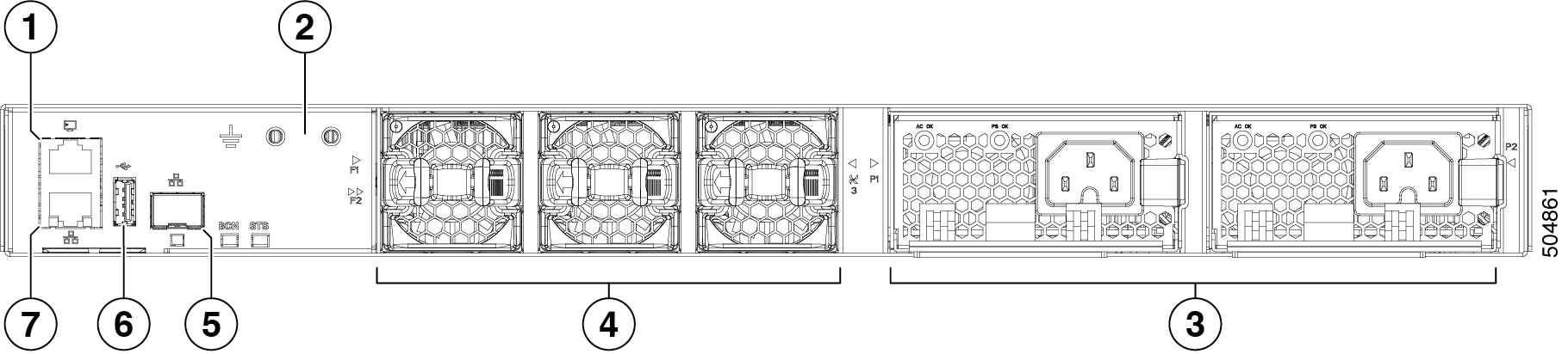
The figure shows the switch features on the power supply side of the chassis.
|
1 |
Console port |
2 |
Grounding pad |
|
3 |
Power supply modules (1 or 2) (AC power supplies shown) with slots numbered 1 (left) and 2 (right) |
4 |
Fan modules (3) with slots numbered from 1 (left) to 3 (right) |
|
5 |
Management port (SFP) |
6 |
USB port |
|
7 |
Management port (RJ45) |
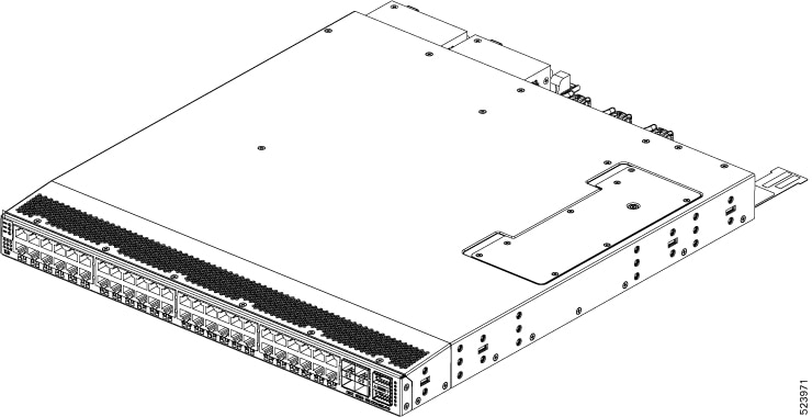
The figure shows the Cisco Nexus 9348GC-FX3 switch.
The fan and power supply modules are field replaceable. You can replace one fan module or one power supply module during operations so long as the other modules are installed and operating. If you have only one power supply installed, you can install the replacement power supply in the open slot before removing the original power supply.
 Caution |
If the switch has port-side intake airflow (burgundy coloring for fan modules), you must locate the ports in the cold aisle. If the switch has port-side exhaust airflow (blue coloring for fan modules), you must locate the ports in the hot aisle. If you locate the air intake in a hot aisle, the switch can overheat and shut down. |
 Feedback