Information About Ethernet Interfaces
The Ethernet ports can operate as standard Ethernet interfaces connected to servers or to a LAN.
The Ethernet interfaces also support Fibre Channel over Ethernet (FCoE). FCoE allows the physical Ethernet link to carry both Ethernet and Fibre Channel traffic.
The Ethernet interfaces are enabled by default.
Interface Command
You can enable the various capabilities of the Ethernet interfaces on a per-interface basis using the interface command. When you enter the interface command, you specify the following information:
-
Interface type—All physical Ethernet interfaces use the ethernet keyword.
-
Slot number:
-
Slot 1 includes all the fixed ports.
-
Slot 2 includes the ports on the upper expansion module (if populated).
-
Slot 3 includes the ports on the lower expansion module (if populated).
-
Slot 4 includes the ports on the lower expansion module (if populated).
-
-
Port number— Port number within the group.
-
Interface type—All physical Ethernet interfaces use the ethernet keyword.
-
For the 5548P and 5548UP, the slot numbers are as follows:
-
Slot 1— includes all the fixed ports.
-
Slot 2—the QSFP+ ports on the GEM (if populated)
-
-
For the 5596UP and 5596T, the slot numbers are as follows:
-
Slot 1— includes all the fixed ports.
-
Slot 2—the QSFP+ ports on the GEM (if populated)
-
Slot 3—the QSFP+ ports on the GEM (if populated)
-
Slot 4—the QSFP+ ports on the GEM (if populated)
-
-
QSFP-module—This is used to identify the GEM breakout port mode.
-
Port number— Port number within the group.
-
switch(config)# interface ethernet QSFP-module/port
The interface numbering convention is extended to support use with a Cisco Nexus Fabric Extender as follows:
switch(config)# interface ethernet [chassis/]slot/port
-
The chassis ID is an optional entry that you can use to address the ports of a connected Fabric Extender. The chassis ID is configured on a physical Ethernet or EtherChannel interface on the switch to identify the Fabric Extender discovered through the interface. The chassis ID ranges from 100 to 199.
Information About Unified Ports
Cisco Nexus unified ports allow you to configure a physical port on a Cisco Nexus device switch as a 1/10-Gigabit Ethernet, Fibre Channel over Ethernet (FCoE), or 2-, 4-, 8-Gigabit native Fibre Channel port.
Currently, most networks have two types of switches for different types of networks. For example, LAN switches carry Ethernet traffic up to Catalyst or Nexus switches carry FC traffic from servers to MDS switches. With unified port technology, you can deploy a unified platform, unified device, and unified wire approach. Unified ports allow you to move from an existing segregated platform approach where you choose LAN and SAN port options to transition to a single, unified fabric that is transparent and consistent with existing practices and management software. A unified fabric includes the following:
-
Unified platform—Uses the same hardware platform and the same software code level and certifies it once for your LAN and SAN environments.
-
Unified device—Runs LAN and SAN services on the same platform switch. The unified device allows you to connect your Ethernet and Fibre Channel cables to the same device.
-
Unified wire—Converges LAN and SAN networks on a single converged network adapter (CNA) and connects them to your server.
A unified fabric allows you to manage Ethernet and FCoE features independently with existing Cisco tools.
Guidelines and Limitations for Unified Ports
-
On the Cisco Nexus 5548UP switch, the 32 ports of the main slot (slot1) are unified ports. The Ethernet ports start from port 1/1 to port 1/32. The Fibre Channel ports start from port 1/32 backwards to port 1/1.
-
For the Cisco Nexus 5596T switch, the last 16 ports (ports 33-48) are Fiber Channel and are configurable as unified ports. The first 32 ports (1-32) are 10GBase-T Ethernet ports only and cannot be configured as unified ports.
Unidirectional Link Detection Parameter
The Cisco-proprietary Unidirectional Link Detection (UDLD) protocol allows ports that are connected through fiber optics or copper (for example, Category 5 cabling) Ethernet cables to monitor the physical configuration of the cables and detect when a unidirectional link exists. When the switch detects a unidirectional link, UDLD shuts down the affected LAN port and alerts the user. Unidirectional links can cause a variety of problems, including spanning tree topology loops.
UDLD is a Layer 2 protocol that works with the Layer 1 protocols to determine the physical status of a link. At Layer 1, autonegotiation takes care of physical signaling and fault detection. UDLD performs tasks that autonegotiation cannot perform, such as detecting the identities of neighbors and shutting down misconnected LAN ports. When you enable both autonegotiation and UDLD, Layer 1 and Layer 2 detections work together to prevent physical and logical unidirectional connections and the malfunctioning of other protocols.
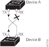
A unidirectional link occurs whenever traffic transmitted by the local device over a link is received by the neighbor but traffic transmitted from the neighbor is not received by the local device. If one of the fiber strands in a pair is disconnected, and if autonegotiation is active, the link does not stay up. In this case, the logical link is undetermined, and UDLD does not take any action. If both fibers are working normally at Layer 1, then UDLD at Layer 2 determines whether those fibers are connected correctly and whether traffic is flowing bidirectionally between the correct neighbors. This check cannot be performed by autonegotiation, because autonegotiation operates at Layer 1.
A Cisco Nexus device periodically transmits UDLD frames to neighbor devices on LAN ports with UDLD enabled. If the frames are echoed back within a specific time frame and they lack a specific acknowledgment (echo), the link is flagged as unidirectional and the LAN port is shut down. Devices on both ends of the link must support UDLD in order for the protocol to successfully identify and disable unidirectional links.
The following figure shows an example of a unidirectional link condition. Device B successfully receives traffic from Device A on the port. However, Device A does not receive traffic from Device B on the same port. UDLD detects the problem and disables the port.
Default UDLD Configuration
The following table shows the default UDLD configuration.
|
Feature |
Default Value |
|---|---|
|
UDLD global enable state |
Globally disabled |
|
UDLD aggressive mode |
Disabled |
|
UDLD per-port enable state for fiber-optic media |
Enabled on all Ethernet fiber-optic LAN ports |
|
UDLD per-port enable state for twisted-pair (copper) media |
Enabled |
UDLD Aggressive and Nonaggressive Modes
UDLD aggressive mode is disabled by default. You can configure UDLD aggressive mode only on point-to-point links between network devices that support UDLD aggressive mode. If UDLD aggressive mode is enabled, when a port on a bidirectional link that has a UDLD neighbor relationship established stops receiving UDLD frames, UDLD tries to reestablish the connection with the neighbor. After eight failed retries, the port is disabled.
To prevent spanning tree loops, nonaggressive UDLD with the default interval of 15 seconds is fast enough to shut down a unidirectional link before a blocking port transitions to the forwarding state (with default spanning tree parameters).
When you enable the UDLD aggressive mode, the following occurs:
-
One side of a link has a port stuck (both transmission and receive)
-
One side of a link remains up while the other side of the link is down
In these cases, the UDLD aggressive mode disables one of the ports on the link, which prevents traffic from being discarded.
Interface Speed
The 5596T switch has 48 base board ports and 3 GEM slots. The first 32 ports are 10GBase-T ports the last 16 ports are SFP+ ports. The 10GBase-T ports support a speed of 1-Gigabit, 10-Gigabit, or Auto. The Auto setting automatically negotiates with the link parser to select either 1-Gigabit or 10-Gigabit speed.
Carrier Delay
 Note |
You can configure the carrier delay timer only on VLAN network interfaces. The timer cannot be configured on physical Ethernet interfaces, port channels, and loopback interfaces. See “Configuring Layer 3 Interfaces,” for information about configuring VLAN network interfaces. |
If a link goes down and comes back up before the carrier delay timer expires, the down state is effectively filtered, and the rest of the software on the device is not aware that a link-down event occurred. A large carrier delay timer results in fewer link-up/link-down events being detected. When you set the carrier delay time to 0, the device detects each link-up/link-down event that occurs.
In most environments, a lower carrier delay time is better than a higher one. The exact value that you choose depends on the nature of the link outages and how long you expect these linkages to last in your network. If your data links are subject to short outages (especially if those outages last less time than it takes for your IP routing to converge), you should set a long carrier delay value to prevent these short outages from causing unnecessary problems in your routing tables. However, if your outages tend to be longer, you might want to set a shorter carrier delay time so that the outages are detected sooner, and the IP route convergence begins and ends sooner. The default carrier-delay time is 100 milliseconds.
Cisco Discovery Protocol
The Cisco Discovery Protocol (CDP) is a device discovery protocol that runs over Layer 2 (the data link layer) on all Cisco-manufactured devices (routers, bridges, access servers, and switches) and allows network management applications to discover Cisco devices that are neighbors of already known devices. With CDP, network management applications can learn the device type and the Simple Network Management Protocol (SNMP) agent address of neighboring devices that are running lower-layer, transparent protocols. This feature enables applications to send SNMP queries to neighboring devices.
CDP runs on all media that support Subnetwork Access Protocol (SNAP). Because CDP runs over the data-link layer only, two systems that support different network-layer protocols can learn about each other.
Each CDP-configured device sends periodic messages to a multicast address, advertising at least one address at which it can receive SNMP messages. The advertisements also contain time-to-live, or holdtime information, which is the length of time a receiving device holds CDP information before discarding it. Each device also listens to the messages sent by other devices to learn about neighboring devices.
The switch supports both CDP Version 1 and Version 2.
Default CDP Configuration
The following table shows the default CDP configuration.
|
Feature |
Default Setting |
|---|---|
|
CDP interface state |
Enabled |
|
CDP timer (packet update frequency) |
60 seconds |
|
CDP holdtime (before discarding) |
180 seconds |
|
CDP Version-2 advertisements |
Enabled |
Error-Disabled State
An interface is in the error-disabled (err-disabled) state when the inteface is enabled administratively (using the no shutdown command) but disabled at runtime by any process. For example, if UDLD detects a unidirectional link, the interface is shut down at runtime. However, because the interface is administratively enabled, the interface status displays as err-disabled. Once an interface goes into the err-disabled state, you must manually reenable it or you can configure an automatic timeout recovery value. The err-disabled detection is enabled by default for all causes. The automatic recovery is not configured by default.
When an interface is in the err-disabled state, use the errdisable detect cause command to find information about the error.
You can configure the automatic err-disabled recovery timeout for a particular err-disabled cause by changing the time variable.
The errdisable recovery cause command provides automatic recovery after 300 seconds. To change the recovery period, use the errdisable recovery interval command to specify the timeout period. You can specify 30 to 65535 seconds.
If you do not enable the err-disabled recovery for the cause, the interface stays in the err-disabled state until you enter the shutdown and no shutdown commands. If the recovery is enabled for a cause, the interface is brought out of the err-disabled state and allowed to retry operation once all the causes have timed out. Use the show interface status err-disabled command to display the reason behind the error.
About Port Profiles
You can create a port profile that contains many interface commands and apply that port profile to a range of interfaces on the Cisco Nexus device. Port profiles can be applied to the following interface types:
-
Ethernet
-
VLAN network interface
-
Port channel
A command that is included in a port profile can be configured outside of the port profile. If the new configuration in the port profile conflicts with the configurations that exist outside the port profile, the commands configured for an interface in configuration terminal mode have higher priority than the commands in the port profile. If changes are made to the interface configuration after a port profile is attached to it, and the configuration conflicts with that in the port profile, the configurations in the interface will be given priority.
You inherit the port profile when you attach the port profile to an interface or range of interfaces, When you attach, or inherit, a port profile to an interface or range of interfaces, the switch applies all the commands in that port profile to the interfaces.
You can have one port profile inherit the settings from another port profile. Inheriting another port profile allows the initial port profile to assume all of the commands of the second, inherited, port profile that do not conflict with the initial port profile. Four levels of inheritance are supported. The same port profile can be inherited by any number of port profiles.
To apply the port profile configurations to the interfaces, you must enable the specific port profile. You can configure and inherit a port profile onto a range of interfaces prior to enabling the port profile; you then enable that port profile for the configurations to take effect on the specified interfaces.
When you remove a port profile from a range of interfaces, the switch undoes the configuration from the interfaces first and then removes the port profile link itself. When you remove a port profile, the switch checks the interface configuration and either skips the port profile commands that have been overridden by directly entered interface commands or returns the command to the default value.
If you want to delete a port profile that has been inherited by other port profiles, you must remove the inheritance before you can delete the port profile.
You can choose a subset of interfaces from which to remove a port profile from among that group of interfaces that you originally applied the profile. For example, if you configured a port profile and configured ten interfaces to inherit that port profile, you can remove the port profile from just some of the specified ten interfaces. The port profile continues to operate on the remaining interfaces to which it is applied.
If you delete a specific configuration for a specified range of interfaces using the interface configuration mode, that configuration is also deleted from the port profile for that range of interfaces only. For example, if you have a channel group inside a port profile and you are in the interface configuration mode and you delete that port channel, the specified port channel is also deleted from the port profile as well.
After you inherit a port profile on an interface or range of interfaces and you delete a specific configuration value, that port profile configuration will not operate on the specified interfaces.
If you attempt to apply a port profile to the wrong type of interface, the switch returns an error.
When you attempt to enable, inherit, or modify a port profile, the switch creates a checkpoint. If the port profile configuration fails, the switch rolls back to the prior configuration and returns an error. A port profile is never only partially applied.
Guidelines and Limitations for Port Profiles
Port profiles have the following configuration guidelines and limitations:
-
Each port profile must have a unique name across interface types and the network.
-
Commands that you enter under the interface mode take precedence over the port profile’s commands if there is a conflict. However, the port profile retains that command in the port profile.
-
The port profile’s commands take precedence over the default commands on the interface, unless the default command explicitly overrides the port profile command.
-
After you inherit a port profile onto an interface or range of interfaces, you can override individual configuration values by entering the new value at the interface configuration level. If you remove the individual configuration values at the interface configuration level, the interface uses the values in the port profile again.
-
There are no default configurations associated with a port profile.
-
A subset of commands are available under the port profile configuration mode, depending on which interface type that you specify.
-
You cannot use port profiles with Session Manager.
Debounce Timer Parameters
Debounce time is the amount of time that an interface waits to notify the supervisor of a link-state change, which in turn decreases traffic loss due to network reconfiguration, or helps bring up link faster or both.
You can configure the debounce timer separately for each Ethernet port and for link up and link down event separately and specify the delay time in milliseconds.
For a link going down, the interface waits to see if the link comes back up within the debounce time. For a link coming up, the interface waits for debounce link-up time before declaring it as UP.
The wait period is a time when the traffic is stopped. By default, the debounce timer is set for 100 milliseconds.
 Caution |
When you enable the port debounce timer the link up and link down detections are delayed, resulting in a loss of traffic during the debounce period. This situation might affect the convergence and reconvergence of some protocols. |
MTU Configuration
The Cisco Nexus device switch does not fragment frames. As a result, the switch cannot have two ports in the same Layer 2 domain with different maximum transmission units (MTUs). A per-physical Ethernet interface MTU is not supported. Instead, the MTU is set according to the QoS classes. You modify the MTU by setting class and policy maps.
Note |
When you show the interface settings, a default MTU of 1500 is displayed for physical Ethernet interfaces and a receive data field size of 2112 is displayed for Fibre Channel interfaces. |
 Feedback