- Preface
- New and Changed Information
- Overview
-
- Configuring Ethernet Interfaces
- Configuring VLANs
- Configuring Private VLANs
- Configuring Access and Trunk Interfaces
- Configuring EtherChannels
- Configuring Virtual Port Channels
- Configuring Rapid PVST+
- Configuring Multiple Spanning Tree
- Configuring STP Extensions
- Configuring the MAC Address Table
- Configuring IGMP Snooping
- Configuring Traffic Storm Control
-
- Configuring Fibre Channel Interfaces
- Configuring Domain Parameters
- Configuring N Port Virtualization
- Configuring VSAN Trunking
- Configuring SAN Port Channel
- Configuring and Managing VSANs
- Configuring and Managing Zones
- Distributing Device Alias Services
- Configuring Fibre Channel Routing Services and Protocols
- Managing FLOGI, Name Server, FDMI, and RSCN Databases
- Discovering SCSI Targets
- Advanced Fibre Channel Features and Concepts
- Configuring FC-SP and DHCHAP
- Configuring Port Security
- Configuring Fabric Binding
- Configuring Fabric Configuration Servers
- Configuring Port Tracking
- Configuration Limits
- Index
Contents
- Configuring FCoE
- Information About FCoE
- Information About FCoE and FIP
- FCoE Initiation Protocol
- FIP Virtual Link Instantiation
- FCoE Frame Format
- VLAN Tagging for FCoE Frames
- FIP Ethernet Frame Format
- Pre-FIP Virtual Link Instantiation
- Information About DCBX
- Data Center Bridging Exchange Protocol
- DCBX Feature Negotiation
- Lossless Ethernet
- Logical Link Up/Down
- Converged Network Adapters
- FCoE Topologies
- Directly Connected CNA Topology
- Remotely Connected CNA Topology
- FCoE Best Practices
- Directly Connected CNA Best Practice
- Remotely Connected CNA Best Practice
- Licensing Requirements for FCoE
- Configuring FCoE
- Enabling FCoE
- Disabling FCoE
- Disabling LAN Traffic on an FCoE Link
- Configuring the FC-Map
- Configuring the Fabric Priority
- Setting the Advertisment Interval
- Configuring LLDP
- Configuring Global LLDP Commands
- Configuring Interface LLDP Commands
- Verifying FCoE Configuration
Configuring FCoE
This chapter describes how to configure Fibre Channel over Ethernet (FCoE) on Cisco Nexus 5000 Series switches. It contains the following sections:
- Information About FCoE
- FCoE Topologies
- FCoE Best Practices
- Licensing Requirements for FCoE
- Configuring FCoE
- Configuring LLDP
- Verifying FCoE Configuration
Information About FCoE
Fibre Channel over Ethernet (FCoE) provides a method of transporting Fibre Channel traffic over a physical Ethernet connection. FCoE requires the underlying Ethernet to be full duplex and to provide lossless behavior for Fibre Channel traffic.
 Note | Lossless behavior on Ethernet is provided by using a priority flow control (PFC) mechanism that prevents packet loss during congestion conditions. |
Cisco Nexus 5000 Series switches support T11-compliant FCoE on all 10-Gigabit Ethernet interfaces.
Information About FCoE and FIP
FCoE Initiation Protocol
The FCoE Initialization Protocol (FIP) allows the switch to discover and initialize FCoE-capable entities that are connected to an Ethernet LAN. Two versions of FIP are supported by the Cisco Nexus 5000 Series switch:
-
FIP—The Converged Enhanced Ethernet Data Center Bridging Exchange (CEE-DCBX) protocol supports T11-compliant Gen-2 CNAs.
-
Pre-FIP—The Cisco, Intel, Nuova Data Center Bridging Exchange (CIN-DCBX) protocol supports Gen-1 converged network adapters (CNAs).
The Cisco Nexus 5000 Series switch detects the capabilities of the attached CNA and switches to the correct FIP mode.
FIP Virtual Link Instantiation
Cisco NX-OS Release 4.1(3)N1(1) adds support for the T11-compliant FIP on the Cisco Nexus 5000 Series switch.
FIP is used to perform device discovery, initialization, and link maintenance. FIP performs the following protocols:
-
FIP Discovery—When a FCoE device is connected to the fabric, it sends out a Discovery Solicitation message. A Fibre Channel Forwarder (FCF) or a switch responds to the message with a Solicited Advertisement that provides an FCF MAC address to use for subsequent logins.
FCoE Virtual Link instantiation— FIP defines the encapsulation of fabric login (FLOGI) , fabric discovery (FDISC), logout (LOGO), and exchange link parameters (ELP) frames along with the corresponding reply frames. The FCoE devices use these messages to perform a fabric login.
-
FCoE Virtual Link maintenance— FIP periodically sends maintenance messages between the switch and the CNA to ensure the connection is still valid.
FCoE Frame Format
FCoE is encapsulated in an Ethernet packet with a dedicated EtherType, 0x8906. That packet has a 4-bit version field. The other header fields in the frame (the source and destination MAC addresses, VLAN tags, and frame markers) are all standard Ethernet fields. Reserved bits pad the FCoE frame to the IEEE 802.3 minimum packet length of 64 bytes.
A Fibre Channel frame consists of 36 bytes of headers and up to 2112 bytes of data for a total maximum size of 2148 bytes. The encapsulated Fibre Channel frame has all the standard headers, which allow it to be passed to the storage network without further modification. To accomodate the maximum Fibre Channel frame in an FC0E frame, the class-fcoe is defined with a default MTU of 2240 bytes.
VLAN Tagging for FCoE Frames
The Ethernet frames that are sent by the switch to the adapter may include the IEEE 802.1Q tag. This tag includes a field for the class of service (CoS) value used by the priority flow control (PFC). The IEEE 802.1Q tag also includes a VLAN field.
The Cisco Nexus 5000 Series switch expects frames from a FIP T11-compliant CNA to be tagged with the VLAN tag for the FCoE VLAN. Frames that are not correctly tagged are discarded.
The switch expects frames from a pre-FIP CNA to be priority tagged with the FCoE CoS value. The switch will still accept untagged frames from the CNA.
FIP Ethernet Frame Format
FIP is encapsulated in an Ethernet packet with a dedicated EtherType, 0x8914. The packet has a 4-bit version field. Along with the source and destination MAC addresses, the FIP packet also contains a FIP operation code and a FIP operation subcode. The following table describes the FIP operation codes.
FIP Operation Code |
FIP Subcode |
FIP Operation |
|---|---|---|
0x0001 |
0x01 |
Discovery Solicitation |
0x02 |
Discovery Advertisement |
|
0x0002 |
0x01 |
Virtual Link Instantiation Request |
0x02 |
Virtual Link Instantiation Reply |
|
0x0003 |
0x01 |
FIP Keep Alive |
0x02 |
FIP Clear Virtual Links |
|
0x0004 |
0x01 |
FIP VLAN Request |
0x02 |
FIP VLAN Notification |
Pre-FIP Virtual Link Instantiation
Pre-FIP virtual link instantiation consists of two phases; link discovery using the Data Center Bridging Exchange protocol (DCBX), which is followed by Fabric Login.
The Cisco Nexus 5000 Series switch is backward compatible with Gen-1 CNAs that operate in pre-FIP mode.
Note | Pre-FIP is also known as the Cisco, Intel, Nuova Data Center Bridging Exchange (CIN-DCBX) protocol. |
Information About DCBX
Data Center Bridging Exchange Protocol
The Data Center Bridging Exchange (DCBX) protocol is an extension of the Link Layer Discovery Protocol (LLDP). DCBX end points exchange request and acknowledgment messages. For flexibility, parameters are coded in a type-length-value (TLV) format.
The Cisco Nexus 5000 Series switch supports two versions of DCBX:
-
CEE-DCBX—The Converged Enhanced Ethernet DCBX is supported on all T11-compliant Gen-2 CNAs
-
CIN-DCBX—The Cisco, Intel, Nuova DCBX is supported on Gen-1 converged network adapters (CNAs). CIN-DCBX is used to perform link detection in addition to other functions.
DCBX runs on the physical Ethernet link between the Cisco Nexus 5000 Series switch and the CNA. By default, DCBX is enabled on Ethernet interfaces. When an Ethernet interface is brought up, the switch automatically starts to communicate with the CNA.
During the normal operation of FCoE between the switch and the CNA, DCBX provides link-error detection.
DCBX is also used to negotiate capabilities between the switch and the CNA and to send configuration values to the CNA.
The CNAs that are connected to a Cisco Nexus 5000 Series switch are programmed to accept the configuration values sent by the switch, allowing the switch to distribute configuration values to all attached CNAs, which reduces the possibility of configuration errors and simplifies CNA administration.
DCBX Feature Negotiation
The switch and CNA exchange capability information and configuration values. The Cisco Nexus 5000 Series switches support the following capabilities:
-
FCoE—If the CNA supports FCoE capability, the switch sends the IEEE 802.1p CoS value to be used with FCoE packets.
-
Priority Flow Control (PFC)—If the adapter supports PFC, the switch sends the IEEE 802.1p CoS values to be enabled with PFC.
-
Priority group type-length-value (TLV)
-
Ethernet logical link up and down signal
-
FCoE logical link up and down signal for pre-FIP CNAs
The following rules determine whether the negotiation results in a capability being enabled:
-
If a capability and its configuration values match between the switch and the CNA, the feature is enabled.
-
If a capability matches, but the configuration values do not match, the following occurs:
-
If the CNA does not support a DCBX capability, that capability remains disabled.
-
If the CNA does not implement DCBX, all capabilities remain disabled.
Note | The Cisco Nexus 5000 Series switch provides CLI commands to manually override the results of the PFC negotiation with the adapter. On a per-interface basis, you can force capabilities to be enabled or disabled. |
Lossless Ethernet
Standard Ethernet is a best-effort medium which means that it lacks any form of flow control. In the event of congestion or collisions, Ethernet will drop packets. The higher level protocols detect the missing data and retransmit the dropped packets.
To properly support Fibre Channel, Ethernet has been enhanced with a priority flow control (PFC) mechanism.
Logical Link Up/Down
The optional N5K-M1404 or N5K-M1008 expansion modules provide native 1/2/4-Gigabit Fibre Channel ports to connect the Cisco Nexus 5000 Series switch to other Fibre Channel devices. On a native Fibre Channel link, some configuration actions (such as changing the VSAN) require that you reset the interface status. When you reset the interface status, the switch disables the interface and then immediately reenables the interface.
If an Ethernet link provides FCoE service, do not reset the physical link because this action is disruptive to all traffic on the link.
The logical link up/down feature allows the switch to reset an individual virtual link. The logical link down is signaled with a FIP Clear Virtual Link message.
For pre-FIP CNAs, the switch sends a DCBX message to request the CNA to reset only the virtual Fibre Channel interface.
Note | If the CNA does not support the logical link level up/down feature, the CNA resets the physical link. In this case, all traffic on the Ethernet interface is disrupted. DCBX-based FC Logical Link Status signaling only applies to FCoE sessions to pre-FIP CNAs. |
Converged Network Adapters
The following types of CNAs are available:
Two generations of CNAs are supported by the Cisco Nexus 5000 Series switch:
-
A FIP adapter uses the FIP to exchange information about its available capabilities and to negotiate the configurable values with the switch.
-
A pre-FIP adapter uses DCBX to exchange information about its available capabilities and to negotiate the configurable values with the switch.
To reduce configuration errors and simplify administration, the switch distributes the configuration data to all the connected adapters.
FCoE Topologies
Directly Connected CNA Topology
The Cisco Nexus 5000 Series switch can be deployed as a Fibre Channel Forwarder (FCF) as shown in the following figure.
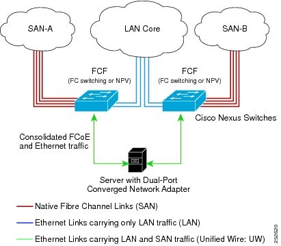
The following rules are used to process FIP frames to avoid the FCF being used as a transit between an FCoE node (ENode) and another FCF. These rules also prevent login sessions between ENodes and FCFs in different fabrics.
-
FIP solicitation and login frames received from the CNAs are processed by the FCF and are not forwarded.
-
If an FCF receives solicitations and advertisements from other FCFs over an interface, the following occurs:
CNAs cannot discover or login to FCFs that are reachable only through a transit Cisco Nexus 5000 Series FCF. The Cisco Nexus 5000 Series switch cannot perform the FCoE transit function between a CNA and another FCF due to hardware limitations.
Because the Cisco Nexus 5000 Series FCF cannot perform the transit FCoE function, you must design your network topology so that the active STP path of FCoE VLANs is always over the directly connected links between the CNA and the FCF. Make sure that you configure the FCoE VLAN on the directly connected links only.
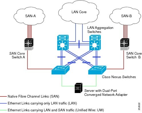
Remotely Connected CNA Topology
The Cisco Nexus 5000 Series switch can be deployed as a Fibre Channel Forwarder (FCF) for remotely connected CNAs, but not as a FIP Snooping Bridge, as shown in the following figure.
The following rules are used to process FIP frames to avoid the FCF being used as a transit between an ENode and another FCF. These rules also prevent login sessions between ENodes and FCFs in different fabrics.
-
FIP solicitation and login frames received from the CNAs are processed by the FCF and are not forwarded.
-
If an FCF receives solicitations and advertisements from other FCFs over an interface, the following occurs:
Because the Cisco Nexus 5000 Series FCF cannot perform the transit FCoE function, you must design your network topology so that the active STP path of FCoE VLANs is always over the directly connected links between the CNA and the FCF. Make sure that you configure the FCoE VLAN on the directly connected links only.
FCoE Best Practices
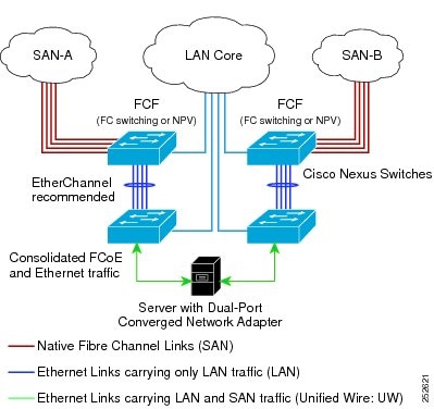
Directly Connected CNA Best Practice
The following figure shows a best practices topology for an access network using directly connected CNAs with Cisco Nexus 5000 Series switches.
Follow these configuration best practices for the deployment topology in the preceding figure:
-
You must configure a unique dedicated VLAN at every converged access switch to carry traffic for each Virtual Fabric (VSAN) in the SAN (for example, VLAN 1002 for VSAN 1, VLAN 1003 for VSAN 2, and so on). If you enable MST, you must use a separate MST instance for FCoE VLANs.
-
You must configure the unified fabric (UF) links as trunk ports. Do not configure the FCoE VLAN as a native VLAN. You must configure all FCoE VLANs as members of the UF links to allow extensions for VF_Port trunking and VSAN management for the virtual Fibre Channel interfaces.
Note
A unified fabric link carries both Ethernet and FCoE traffic.
-
You must configure the UF links as spanning-tree edge ports.
-
You must not configure the FCoE VLANs as members of Ethernet links that are not designated to carry FCoE traffic because you want to ensure the scope of the STP for the FCoE VLANs is limited to UF links only.
-
If the converged access switches (in the same SAN fabric or in another) need to be connected to each other over Ethernet links for a LAN alternate path, then such links must explicitly be configured to exclude all FCoE VLANs from membership. This action ensures that the scope of the STP for the FCoE VLANs is limited to UF links only.
-
You must use separate FCoE VLANs for FCoE in SAN-A and SAN-B.
Note | All Gen-1 (pre-FIP) and Gen-2 (FIP) CNAs are supported in a directly connected topology. |
Remotely Connected CNA Best Practice
The following figure shows a best practices topology for an access network using remotely connected CNAs with Cisco Nexus 5000 Series switches.
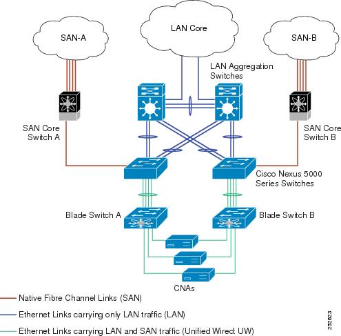
Follow these configuration best practices for the deployment topology in the preceding figure:
-
You must configure a unique dedicated VLAN at every converged access switch to carry traffic for each Virtual Fabric (VSAN) in the SAN (for example, VLAN 1002 for VSAN 1, VLAN 1003 for VSAN 2, and so on). If you enable MST, you must use a separate MST instance for FCoE VLANs.
-
You must configure the unified fabric (UF) links as trunk ports. Do not configure the FCoE VLAN as a native VLAN. You must configure all FCoE VLANs as members of the UF links to allow extensions for VF_Port trunking and VSAN management for the virtual Fibre Channel interfaces.
Note
A unified fabric link carries both Ethernet and FCoE traffic.
-
You must configure the CNAs and the blade switches as spanning-tree edge ports.
-
A blade switch must connect to exactly one Cisco Nexus 5000 Series converged access switch, preferably over an EtherChannel, to avoid disruption due to STP reconvergence on events such as provisioning new links or blade switches.
-
You must configure the Cisco Nexus 5000 Series converged access switch with a better STP priority than the blade switches that are connected to it. This requirement allows you to create an island of FCoE VLANs where the converged access switch is the spanning-tree root and all the blade switches connected to it become downstream nodes.
-
Do not configure the FCoE VLANs as members of Ethernet links that are not designated to carry FCoE traffic because you want to ensure that the scope of the STP for the FCoE VLANs is limited to UF links only.
-
If the converged access switches and/or the blade switches need to be connected to each over Ethernet links for the purposes of LAN alternate pathing, then such links must explicitly be configured to exclude all FCoE VLANs from membership. This will ensure the scope of the spanning-tree protocol for FCoE VLANs is limited to UF links only.
-
You must use separate FCoE VLANs for FCoE in SAN-A and SAN-B.
Note | A remotelyconnected topology is supported only with Gen-2 (FIP) CNAs. |
Licensing Requirements for FCoE
On Cisco Nexus 5000 Series switches, FCoE capability is included in the Storage Protocol Services License.
Before using FCoE capabilities, you must ensure the following:
Configuring FCoE
Enabling FCoE
You can enable FCoE on the switch.
You need to have the FC_FEATURES_PKG (N5010SS or N5020SS) license installed.
1.
switch# configure terminal
2.
switch(config)# feature fcoe
DETAILED STEPS
| Command or Action | Purpose |
|---|
This example shows how to enable FCoE on the switch:
switch# configure terminal
switch(config)# feature fcoe
Disabling FCoE
After you disable FCoE, all FCoE commands are removed from the CLI and the FCoE configuration is deleted .
1.
switch#
configure terminal
2.
switch(config)#
no feature fcoe
DETAILED STEPS
| Command or Action | Purpose |
|---|
This example shows how to disable FCoE on the switch:
switch# configure terminal
switch(config)# no feature fcoe
Disabling LAN Traffic on an FCoE Link
You can disable LAN traffic on an FCoE link.
DCBX allows the switch to send a LAN Logical Link Status (LLS) message to a directly-connected CNA. Enter the shutdown lan command to send an LLS-Down message to the CNA. This command causes all VLANs on the interface that are not enabled for FCoE to be brought down. If a VLAN on the interface is enabled for FCoE, it continues to carry SAN traffic without any interruption.
1.
switch#
configure terminal
2.
switch(config)#
interface
ethernet
slot/port
3.
switch(config-if)#
shutdown lan
4.
(Optional) switch(config-if)#
no shutdown lan
DETAILED STEPS
Configuring the FC-Map
You can prevent data corruption due to cross-fabric talk by configuring an FC-Map which identifies the Fibre Channel fabric for this Cisco Nexus 5000 Series switch. When the FC-Map is configured, the switch discards the MAC addresses that are not part of the current fabric.
1.
switch#
configure terminal
2.
switch(config)#
fcoe fcmap
fabric-map
3.
(Optional)
switch(config)#
no fcoe fcmap
fabric-map
DETAILED STEPS
This example shows how to configure the global FC-Map:
switch# configure terminal
switch(config)# fcoe fcmap 0e.fc.2a
Configuring the Fabric Priority
The Cisco Nexus 5000 Series switch advertises its priority. The priority is used by the CNAs in the fabric to determine the best switch to connect to.
1.
switch#
configure terminal
2.
switch(config)#
fcoe fcf-priority
fabric-priority
3.
(Optional)
switch(config)#
no fcoe fcf-priority
fabric-priority
DETAILED STEPS
This example shows how to configure the global fabric priority:
switch# configure terminal
switch(config)# fcoe fcf-priority 42
Setting the Advertisment Interval
You can configure the interval for Fibre Channel fabric advertisment on the switch.
1.
switch#
configure terminal
2.
switch(config)#
fcoe fka-adv-period
inverval
3.
(Optional)
switch(config)#
no fcoe fka-adv-period
interval
DETAILED STEPS
This example shows how to configure the advertisement interval for the fabric:
switch# configure terminal
switch(config)# fcoe fka-adv-period 42
Configuring LLDP
Configuring Global LLDP Commands
You can set global LLDP settings. These settings include the length of time before discarding LLDP information received from peers, the length of time to wait before performing LLDP initialization on any interface, and the rate at which LLDP packets are sent.
To configure LLDP settings, perform this task:
1.
switch#
configure terminal
2.
switch(config)#
lldp {holdtime
seconds |
reinit
seconds |
timer
seconds}
3.
switch(config)#
no lldp {holdtime |
reinit |
timer}
DETAILED STEPS
This example shows how to set LLDP timer option to 15 seconds:
switch# configure terminal
switch(config)# lldp timer 15
Configuring Interface LLDP Commands
To configure the LLDP feature for a physical Ethernet interface, perform this task:
1.
switch#
configure terminal
2.
switch(config)#
interface
type
slot/port
3.
switch(config-if)# [no] lldp {receive |
transmit}
DETAILED STEPS
This example shows how to set an interface to transmit LLDP packets:
switch# configure terminal
switch(config)# interface ethernet 1/2
switch(config-if)# lldp transmit
This example shows how to configure an interface to disable LLDP:
switch# configure terminal
switch(config)# interface ethernet 1/2
switch(config-if)# no lldp transmit
switch(config-if)# no lldp receive
Verifying FCoE Configuration
To verify FCoE configuration information, perform one of these tasks:
|
Command |
Purpose |
|---|---|
| switch# show fcoe |
Displays whether FCoE is enabled on the switch. |
| switch# show fcoe database |
Displays the contents of the FCoE database. |
| switch# show interface [interface number] fcoe |
Displays the FCoE settings for an interface or all interfaces. |
| switch# show lldp |
Displays LLDP configuration. |
This example shows how to verify that the FCoE capability is enabled:
switch# show fcoe
Global FCF details
FCF-MAC is 00:0d:ec:6d:95:00
FC-MAP is 0e:fc:00
FCF Priority is 128
FKA Advertisement period for FCF is 8 seconds
This example shows how to display the FCoE database:
switch# show fcoe database
-------------------------------------------------------------------------------
INTERFACE FCID PORT NAME MAC ADDRESS
-------------------------------------------------------------------------------
vfc3 0x490100 21:00:00:1b:32:0a:e7:b8 00:c0:dd:0e:5f:76
This example shows how to display the FCoE settings for an interface.
switch# show interface ethernet 1/37 fcoe
Ethernet1/37 is FCoE UP
vfc3 is Up
FCID is 0x490100
PWWN is 21:00:00:1b:32:0a:e7:b8
MAC addr is 00:c0:dd:0e:5f:76
This example shows how to display LLDP interface information:
switch# show lldp interface ethernet 1/2
tx_enabled: TRUE
rx_enabled: TRUE
dcbx_enabled: TRUE
Port MAC address: 00:0d:ec:a3:5f:48
Remote Peers Information
No remote peers exist
This example shows how to display LLDP neighbor information:
switch# show lldp neighbors
LLDP Neighbors
Remote Peers Information on interface Eth1/40
Remote peer's MSAP: length 12 Bytes:
00 c0 dd 0e 5f 3a 00 c0 dd 0e 5f 3a
LLDP TLV's
LLDP TLV type:Chassis ID LLDP TLV Length: 7
LLDP TLV type:Port ID LLDP TLV Length: 7
LLDP TLV type:Time to Live LLDP TLV Length: 2
LLDP TLV type:LLDP Organizationally Specific LLDP TLV Length: 55
LLDP TLV type:LLDP Organizationally Specific LLDP TLV Length: 5
LLDP TLV type:END of LLDPDU LLDP TLV Length: 0
Remote Peers Information on interface Eth1/34
Remote peer's MSAP: length 12 Bytes:
00 0d ec a3 27 40 00 0d ec a3 27 69
LLDP TLV's
LLDP TLV type:Chassis ID LLDP TLV Length: 7
LLDP TLV type:Port ID LLDP TLV Length: 7
LLDP TLV type:Time to Live LLDP TLV Length: 2
LLDP TLV type:LLDP Organizationally Specific LLDP TLV Length: 55
LLDP TLV type:LLDP Organizationally Specific LLDP TLV Length: 5
LLDP TLV type:END of LLDPDU LLDP TLV Length: 0
Remote Peers Information on interface Eth1/33
Remote peer's MSAP: length 12 Bytes:
00 0d ec a3 27 40 00 0d ec a3 27 68
LLDP TLV's
LLDP TLV type:Chassis ID LLDP TLV Length: 7
LLDP TLV type:Port ID LLDP TLV Length: 7
LLDP TLV type:Time to Live LLDP TLV Length: 2
LLDP TLV type:LLDP Organizationally Specific LLDP TLV Length: 55
LLDP TLV type:LLDP Organizationally Specific LLDP TLV Length: 5
LLDP TLV type:END of LLDPDU LLDP TLV Length: 0
This example shows how to display LLDP timer information:
switch# show lldp timers
LLDP Timers
holdtime 120 seconds
reinit 2 seconds
msg_tx_interval 30 seconds
This example shows how to display LLDP counters:
switch# show lldp traffic
LLDP traffic statistics:
Total frames out: 8464
Total Entries aged: 6
Total frames in: 6342
Total frames received in error: 2
Total frames discarded: 2
Total TLVs unrecognized: 0