Renewable Energy: Offshore Wind Farm 1.3 Design Guide
Available Languages
Bias-Free Language
The documentation set for this product strives to use bias-free language. For the purposes of this documentation set, bias-free is defined as language that does not imply discrimination based on age, disability, gender, racial identity, ethnic identity, sexual orientation, socioeconomic status, and intersectionality. Exceptions may be present in the documentation due to language that is hardcoded in the user interfaces of the product software, language used based on RFP documentation, or language that is used by a referenced third-party product. Learn more about how Cisco is using Inclusive Language.
- US/Canada 800-553-2447
- Worldwide Support Phone Numbers
- All Tools
 Feedback
 Feedback
Introduction to Offshore Wind Farm
Cisco Solution for Renewable Energy Offshore Wind Farms
Offshore Wind Farm Cisco Validated Design
Scope of Wind Farm Release 1.3
New Capabilities in Offshore Wind Farm Release 1.3
Offshore Wind Farm Places in the Network
Wind Farm Actors in the Network
Solution Design Considerations
TAN Non-HA Design Considerations
TAN High Availability Design with REP
Resilient Ethernet Protocol Ring
Offshore Substation Network and Building Blocks
OSS DMZ and Third-Party Network
Network VLANs and Routing Design
BGP EVPN VXLAN Network Design for Turbine Network
Turbine network Underlay Design
Turbine network VXLAN Overlay Design
Cisco Wi-Fi Architecture for Off-Shore Windfarm
Use case for Service Operations Vessel Wireless Backhaul within a Wind Farm
Hardware Redundancy and High-Availability
BATS FAST 5.8 Intelligent Antenna System
IW Monitor: Centralized Management of URWB Infrastructure
URWB: Terminology and Miscellaneous Configurations
URWB Mobility Architecture: Layer 2 Fluidity
Fluidity Advanced Handoff Tuning for SOV Radios
URWB Fluidity Advanced: Large Network Optimization
IW9167E/IEC6400 Mesh End Redundancy and High Availability
URWB Access Layer: Fast Convergence on Failure
Link Backhaul Check: Handoff Inhibition
Mesh-End Backhaul Check: Handoff Inhibition
Onboard Radio Redundancy: Failover and Recovery
SCADA Applications and Protocols
Open Platform Communications Unified Architecture
Turbine Operator Network Design
OSS (third-party) Turbine Operator Core Network Ring Design
OSS (third-party) Turbine Operator Aggregation Network Design
Farm Area SCADA Network (FSN) Design
Turbine SCADA Network (TSN) Design
TSN Non-HA Design Considerations
TSN High Availability Design with REP
Multi-level advanced REP rings design across Cabinets
Media Redundancy Protocol (MRP) Ring design for FSN
MRP Ring Design Considerations
Turbine SCADA network timing synchronization
PTP over MRP Design Considerations
Network Management and Automation
Device Discovery and Onboarding
Device Plug-n-Play Onboarding Using Catalyst Center
FAN REP Ring Provisioning using Catalyst Center REP Automation Workflow
REP Ring Design Considerations, Limitations, and Restrictions
Day N Operations and Templates
Security Design Considerations
Security Approach and Philosophy
Wind Farm Network Security Use Cases and Features
Advantages of Network Segmentation
Cisco Secure Network Analytics (Stealthwatch)
Flexible NetFlow Data Collection
Cisco Secure Network Analytics for Windfarm Network Security
Cisco Secure Network Analytics for Abnormal Traffic Detection
Operational Technology Flow and Device Visibility using Cisco Cyber Vision
Cyber Vision Design Considerations
Wind Farm Cyber Vision Network Sensors
Cisco Cyber Vision’s SEA Architecture and Core Components
Cisco Cyber Vision’s SEA in Wind Farm Network Design
Design Requirements & Considerations
Turbine Operator Network Security Design
MACsec Encryption in Turbine Operator Network
Network micro-segmentation using Private VLAN
NERC CIP Compliance Features and Guidance
CIP-005-7 - Electronic Security Perimeter(s)
CIP-007-6 – System Security Management
CIP-008-6 – Incident Reporting and Response Planning
CIP-010-4 – Configuration Change Management and Vulnerability Assessments
CIP-011-3 – Information Protection
CIP-013-2 – Supply Chain Risk Management
Network Scale and High Availability Summary
Wind Farm Operator Network High Availability Summary
FAN Aggregation High Availability
OSS and ONSS Core High Availability
Cisco Catalyst Center Redundancy
Cisco SD-WAN Validator SD-WAN Validator Orchestrator
Cisco SD-WAN SD-WAN Controller
Cisco SD-WAN Manager SD-WAN Manager Clustering
Turbine operator Network High Availability Summary
SCADA Core Network High Availability
Turbine Operator Compact Onshore Substation
Compact Onshore Substation Use Cases
Compact Onshore Substation Network Architecture
Core Network and Routing design considerations
WAN Edge with FlexVPN network design
Cisco IR1101 as WAN Edge Router
Cisco Catalyst 8300 Series Edge Platform as HER
Farm Area SCADA Network (FSN) REP Ring Design
FSN with MRP and REP Rings Design
FSN with MRP and REP Rings Design
Turbine SCADA Network (TSN) Design with REP
Compact Substation Network Security
Compact Substation Network Segmentation using Private VLAN
Zone Based Firewall (ZBFW) Design
Network Visibility using NetFlow
Compact Substation Quality of Service
Design Considerations on Core Switch
Introduction to Offshore Wind Farm
Most countries are investing in renewable energy generation to accelerate the move toward carbon neutrality. The following technologies are growing steadily and being deployed at scale:
● Onshore and offshore wind
● Onshore solar farms
● Onshore battery storage
Other renewable technologies also are being researched and developed, such as wave, tidal, and energy storage technologies. We will start to see innovative renewable energy deployments in the future.
Some countries are leading the push to integrate renewable energy into the grid. China and the UK are examples of countries that are leading the way with large deployments of wind farms, both onshore and offshore. European countries in general are setting big targets for offshore wind farms. And the United States is predicted to become a major offshore wind energy producer in the coming decade. Cisco can help with renewable energy technologies, in onshore and offshore wind farms, onshore solar farms, and onshore battery storage facilities. This document focusses on the complexities that offshore wind farms are facing and the solutions that Cisco offers.
Deploying and operating renewable energy technologies can be challenging: they need to operate in harsh and remote locations, a secure and reliable network is required, and that network needs to work flawlessly with the various OT and IT technologies that form the solution.
As digital technology is increasingly required to operate remote distributed energy resource locations, networking and communication equipment must be installed with close attention paid to ease of operations, management, and security. Cisco validated designs are simple, scalable, and flexible. They focus on operational processes that are field-friendly and don’t require a technical wizard. Our centralized network device management (Cisco Catalyst Center) and strong networking asset operation capabilities eliminate the need for manual asset tracking and the inconsistencies in field deployments from one site to another. Integration with operations ensures that field technicians can easily deploy and manage devices without the need for IT support, while IT and OT teams have full visibility and control of the deployed equipment.
Additionally, Cisco provides a wide range of connectivity options, ranging from fiber to cellular or high-speed wireless where hardwired connections are not available.
Cisco has launched a complete validated design for offshore wind farms. This design focusses on an end-to-end architecture for the asset operator’s network, including both onshore and offshore locations.
This document refers to the following stakeholders:
● Wind farm operator: The asset operator responsible for the daily operations and administration of a wind farm as a power-producing entity. Many operators are also involved in the development, ownership, and construction of the wind farm. Operators sell power that is produced to public utility companies, typically with long-term fixed price contracts in place.
● Wind farm owner (asset owner): Typically, a consortium of parties such as public utilities or oil and gas companies and financing companies. There are also dedicated renewable energy companies and others who invest in this area. Many wind farm owners also are operators. Many such companies are dedicated renewable companies or renewable energy branches of traditional utilities or oil and gas companies.
● Turbine supplier: Wind turbine suppliers design, test, and manufacture wind turbine equipment, including wind turbine generators (WTGs), and ancillary systems such as supervisory control and data acquisition (SCADA) and power automation. These suppliers also provide ongoing support and maintenance services (O&M) for many wind farm operators. It is typical for the monitoring and maintenance of the wind turbine network to be outsourced to these same suppliers.
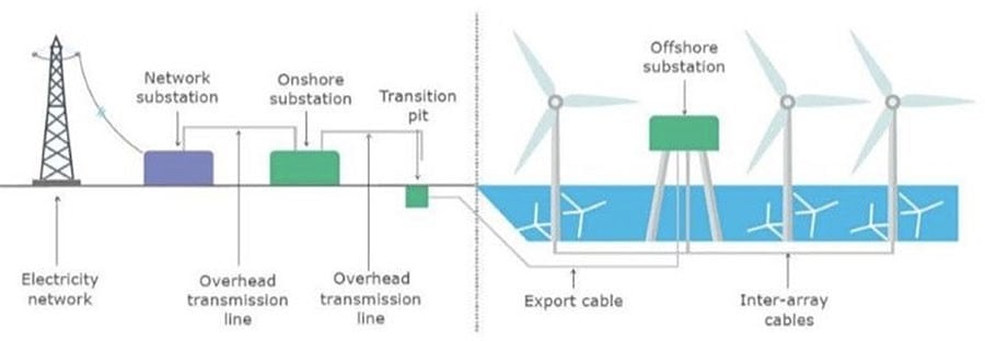
● Offshore transmission owner (OFTO): Offshore wind farms are connected to the onshore grid by an export cable system. Regulatory requirements in many countries prohibit power generators from owning transmission assets. Therefore, the export cable often is owned and operated by another third-party, the OFTO. Developers, who often also are the wind farm owners or operators, divest the export cable system to a third-party through a regulated auction. In some regions, the requirement to divest the transmission assets (export cable systems) is not required.
● Grid utility: A traditional power grid operator that provides the connection point for exported power from a wind farm can be either a transmission system operator (TSO), a distribution network operator (DNO), or a distribution system operator (DSO). Public utilities that are also wind farm owners separate the grid and renewable businesses usually due to strict regulatory requirements.
Cisco Solution for Renewable Energy Offshore Wind Farms
Offshore wind farms are large infrastructure deployments with multiple locations. They include the following:
● Onshore substation
● Offshore substation (platform offshore)
● Offshore wind turbines (ranging from 50 to 300 turbines)
● Onshore operations and maintenance offices
● Offshore service operations vessels (SOV), which provide worker accommodations, offices, and workshops while offshore
Reliable and secure connectivity is key for providing monitoring and control of these offshore and therefore remote assets. Without a reliable and secure communications infrastructure, monitoring and control would be challenging.
From the offshore wind farm operator’s viewpoint, the network needs to be easy to deploy, monitor, upgrade, and troubleshoot.
The network design also needs to be standardized to enable easy specification and procurement at the early stages of a project. Avoiding both bespoke work and delivering different architectures for each project should enable a speedier project delivery phase.
A standardized solution is required that provides the flexibility to meet these needs while facilitating a clear path forward as complexity and scale evolve (for example, larger wind farms, increased number of devices and applications, and increased reliability).
Offshore Wind Farm Cisco Validated Design
Cisco has developed a complete Cisco Validated Design (CVD) for offshore wind farm projects. It provides a blueprint solution for all phases of a project, from specification and procurement to deployment.
The CVD includes networking infrastructure from offshore wind turbine through offshore platforms to the onshore WAN interface point and connectivity to the wind farm operator’s control center.
The CVD is modular to allow for varying wind farm sizes, so it can be adapted for any number of turbines. It provides resilient architectures to allow for fault conditions, and includes cyber security built in from the start.
This CVD offers the following key benefits:
● Flexible deployment options: Support for simple to advanced solutions that cover various deployment options (scalable for small to large wind farms). A modular design that can adjust to the various sizes of wind farms that are deployed. Providing a flexible platform for the deployment of future services and applications.
● Rugged and reliable network equipment: Network equipment designed for harsh offshore environments where required. The ability for network equipment to operate in space-constrained locations and tough environmental conditions.
● Simplified provisioning: Automation and simple onboarding, monitoring, and management of remote networking assets with centralized monitoring and management of multiple wind farm networks.
● Simplified operations: Increased operational visibility, minimized outages, and faster remote issue resolution. Compliance of network device configurations (changes from a known baseline are flagged) and firmware and powerful analytics to provide deep visibility of the network assets.
● Multi-level security: End-to-end robust security capabilities to protect the infrastructure and associated services, monitor traffic flows, and provide control points for interfacing to third-party networks and equipment. Vulnerability information for discovered assets and asset reporting to aid regulatory compliance (for example, NIS 2 and NERC CIP).
The validated design is built on the following functional blocks:
● Wind farm operator data center
● Wind farm wide area network (WAN)
● Onshore DMZ
● Onshore substation
● Offshore DMZ
● Offshore substation
● Turbine Operator network
● Power control and metering (PCM) network
● Turbine plant IT network (for example, enterprise and plant services)
● Service SOVs
● Operations and maintenance buildings (O&M)
● Turbine Operator Compact Onshore Substation
The validated design allows customers or partners to select the parts are applicable to a particular project or deployment or use the complete end-to-end architectures.
Scope of Wind Farm Release 1.3
This Design Guide provides network architecture and design guidance for the planning and subsequent implementation of a Cisco Renewable Energy Wind Farm solution. In addition to this Design Guide, Cisco Wind Farm Solution Implementation Guide provides more specific implementation and configuration guidance with sample configurations.
This Release 1.3 supersedes and replaces the Cisco Offshore Wind Farm Release 1.2 Design Guide.
New Capabilities in Offshore Wind Farm Release 1.3
The turbine operator in an offshore wind farm is responsible for the daily operations and administration of turbines in a wind farm as a power-producing entity. Many operators are also involved in the development, ownership, and construction of the wind farm. Operators sell power that is produced to public utility companies, typically with long-term fixed price contracts in place. Turbine operators like Siemens, Vestas etc., monitor and maintain the wind turbine network with the help of turbine suppliers.
● Turbine Operator Network design in Offshore Substation (OSS) which includes Farm Area SCADA network (FSN), Turbine SCADA Network (TSN) with highly available and resilient network architecture across different OSS geo-locations.
● Turbine Operator network design with:
◦ Media Redundancy Protocol (MRP) ring of FSN up to 20 nodes along with core and FSN REP rings on IE9320 switch
◦ Timing synchronization in turbine SCADA network using Precision Time Protocol (PTP) over MRP ring
● Wind Farm Asset Operator Network architecture with:
◦ BGP EVPN VXLAN fabric L2 overlay between turbine base and OSS core switches with OSPF based L3 underlay (Optional)
◦ Secure Remote Access of OT assets connected to wind turbines, using combined Cyber Vision (CV) and Secure Equipment Access (SEA) IOx application on turbine switches
The following architectural blocks are out of the scope of this CVD:
● Backhaul design for WAN handoff routers
● Typical service provider or customer MPLS network or other fixed connectivity options (microwave, fiber, and so on).
● Data center network design
Offshore Wind Farm Places in the Network
Figure 1 shows the places that an offshore wind farm has in a network.
 |
● Wind turbine generator (WTG)
● Offshore substation (OSS)
● Onshore substation (ONSS)
● Service operations vessel (SOV)
● Crew transfer vessel (CTV)
Wind Farm solution architecture network building blocks are defined based on the places in the offshore wind farms.
The communications options that are available at a given site greatly influence the outcomes and capabilities for any use case. The availability of dependable lower latency, high bandwidth connectivity (such as fiber, LTE/5G cellular, and Wi-Fi) allows for more advanced network and data service options, while sites with bandwidth constrains may be limited to simpler use cases such as remote management and monitoring. Table 1 lists the key use cases in an offshore wind farm.
Table 1. Wind farm use cases
| Use Case |
Type of Services |
Description |
| WTG SCADA |
● Turbine telemetry
● Fire detection
● Turbine ancillary systems
● Weather systems
|
● Telemetry data collection associated with turbine systems and components.
● Detection of smoke and fire within the turbine.
● Telemetry data collection associated with ancillary systems (for example, elevator, navigation lights).
● Data from weather-related systems such as radar for offshore farms, wind speed anemometers.
|
| Process and control systems (ONSS, OSS, other miscellaneous systems) |
● Heating and ventilation systems
● Public announcement and general alarm (PAGA) systems
● Backup generators
● Fire detection systems
|
● Heating, ventilation, and air conditioning (HVAC) systems.
● Audio systems for announcements and alarms.
● Generators for emergency power.
● Fire detection systems.
|
| Marine-related Systems |
● Tetra, VHF, UHF Radio
● Automatic identification system (AIS)
● Radar systems
|
● Ship and worker radio systems.
● Shipping identification system.
● Radar for SOV management.
|
| Enterprise services |
● IP telephony
● Corporate network access
● Guest network access
|
● Enterprise voice communications for workers.
● Fixed and mobile handsets (Wi-Fi).
● General network access for enterprise services such as email, file sharing, video, and web.
● Basic internet access for subcontractors.
|
| Physical security |
● Closed circuit television (CCTV)
● Access control
|
● Physical security monitoring of turbine assets and areas around turbines for safety and security.
● Intrusion detection and entry into areas such as O&M offices and turbine towers.
|
| Miscellaneous systems |
● Bat and bird monitors
● Radar
● Lightning detection systems
● Lidar (turbine monitoring)
|
● Detection of protected wildlife.
● Additional radar equipment as specified by certain bodies (military, Coast Guard, and so on).
● Detection of lightning strikes.
● Monitoring of turbine performance and blade dynamics.
|
| SOV connectivity |
● IP telephony
● Wireless network access (Wi-Fi)
|
● Enterprise. Voice communication for workers.
● Fixed and mobile handsets.
● Wi-Fi access points within SOVs to provide enterprise network access for staff and provide IP telephone coverage.
|
| Environmental sensors |
● Heat and humidity
● Door open and close
● Machine temperature
|
● Turbine nacelle or tower and external measurements.
● Turbine tower, external ancillary cabinets.
● Machine casing or transformer case temperature.
|
| Location-based services |
Personnel location and man down (for lone worker) |
● Wi-Fi access points providing Bluetooth capability for short-range personnel devices for location and man down worker safety.
|
| Tubine Operator Network Services |
Turbine operational telemetry data collection |
● Turbine monitor and operational data collection using SCADA systems.
● OPC-UA gateway/server which translates turbine telemetry data (For example, SCADA MODBUS) into OPC-UA protocol messages.
Provide turbine telemetry data as OPC-UA protocol messages to asset operator on demand. |
Wind Farm Actors in the Network
Various wind farm use cases and places need different endpoints or actors in the network. The following actors are needed in a wind farm network to deliver the features for the use cases that the previous section describes. These actors usually are key to operating a renewable energy site, providing both monitoring and control capabilities.
● CCTV cameras: Physical safety and security IP cameras
● IP phones: Voice over IP (VoIP) telephony devices
● Programmable logic controller (PLC) devices and input and output (I/O) controllers: Power systems protection and control
● Intelligent electronic devices (IED): Power systems protection and control
● Wi-Fi access points: Provide corporate IT Wi-Fi access
● Cisco Ultra Reliable Wireless Backhaul (URWB) access points: Provide wireless backhaul for SOV connectivity
● Wind turbine monitoring and control: SCADA and monitoring systems
● Fire detection and alarming devices or sensors
● HVAC systems
● Environmental and weather systems: Sensors that are associated with monitoring weather and environmental conditions
● Lightning detection: Sensors that are associated with lightning detection
● Marine systems (radar, radio)
Each actor in an offshore wind farm requires network communication with other actors or application servers in the offshore substation (OSS) and control or operations center based on use case requirements. Table 2 lists the traffic types and flow in the offshore wind farms places in the network.
Table 2. Network Segments and Design Use Cases
| Traffic Type |
Traffic Flows in the Network |
| Video traffic (CCTV cameras) |
● Turbine nacelle to control center or OSS: CCTV camera in turbine nacelle switch streaming live video to video server in the control center or OSS infrastructure
● Turbine base switch to control center: CCTV camera in base switch streaming live video to a video server in the Control Center or OSS Infrastructure
|
| SCADA data for monitoring and control (PLCs and I/O devices that are external to the turbine supplier’s dedicated SCADA network))i.e., wind farm operator SCADA |
● Traffic within turbine nacelle: PLC and I/O devices communication using SCADA protocols (for examples, DNP3, MODBUS, or T104)
● Turbine base switch to nacelle: PLC in turbine base switch to an I/O device in nacelle using SCADA protocols (for example: DNP3, MODBUS, or T104)
● Traffic within turbine base switch: Communication between PLC and I/O devices in a turbine base switch
● Turbine base switch to base: Communication between PLC in a turbine base switch and I/O device in another turbine base switch
|
| IP telephony voice traffic (IP phones) |
● Maintenance and operations personnel voice communication between turbine base switch or nacelle and OSS
● Maintenance and operations personnel voice communication between turbine base switch networks
● Maintenance and operations personnel voice communication between an SOV and turbine base switch or OSS networks
|
| Wi-Fi traffic (Wi-Fi APs) |
● Turbine nacelle to OSS infrastructure or control center): Workforce AP in nacelle to WLC in the OSS network
● Turbine base switch to OSS infrastructure or control center
● Workforce AP in a turbine base switch to WLC in the OSS network
● Workforce corporate network access from offshore wind farm
● Guest internet wireless access from offshore and onshore substation.
|
| Offshore and onshore power automation and control SCADA traffic (IEDs, switchgear, other substation OT devices if any) |
● Turbine nacelle switch to OSS infrastructure
● Turbine base switch to OSS infrastructure
● Management traffic between IEDs and SCADA systems in the OSS and IEDs and SCADA devices connected turbine nacelle or turbine switches.
|
| Cisco Ultra Reliable Wireless Backhaul (URWB) traffic |
● SOV wireless connectivity using a URWB network from turbine nacelle or turbine switch or OSS network
|
| Turbine Operator network traffic (dedicated turbine Operator SCADA network provided by a turbine manufacturer) |
● SCADA OPC-UA protocol traffic between OSS DMZ and OSS infrastructure network
● SCADA OT Protocols (DNP3/MODBUS IP) to OPC-UA protocol messages translation (OPC-UA gateway) between IED, Switchgear and OPC-UA server in OSS
|
| SD-WAN and network management traffic (OMP, SSH, SNMP and network control protocols, and so on) |
● Management traffic from ONSS and OSS via the WAN to the control center
● Management traffic related to Cisco SD-WAN and Catalyst Center network management platform
|
| Auxiliary systems traffic (HVAC, fire, lighting detection, environmental sensors) |
Turbine nacelle and switch to OSS infrastructure or control center |
Offshore wind farm solution architecture is built on the following functional blocks:
● Wind farm operator control center (includes data center and security operations center): Hosts wind farm IT and OT data center applications and servers such as Cisco Catalyst Center, Cisco ISE, AD server, DHCP server, Cisco Cyber Vision Center (CVC), and more.
● Wind farm wide area network (WAN): A backhaul network for interconnecting a wind farm onshore substation with a control center. It can be a privately owned MPLS network, a service provider LTE network, or a Cisco SD-WAN managed network.
● Onshore substation (ONSS): A remote site in a wind farm that interconnects an offshore substation with a control center via a WAN.
● Offshore Substation (OSS): Consists of offshore core network and infrastructure applications to provide network connectivity and application access to wind turbine bases and nacelle switches and their IT and OT endpoints.
● Farm area network (FAN): An aggregation network that connects multiple wind turbines base switches and to their aggregation switches.
● Turbine area network (TAN): A switched layer 2 network typically formed by one or more nacelle switches in a wind turbine.
● SOV: Wind farm network operation and maintenance vehicle that moves around offshore wind farms and connects to TAN and OSS or ONSS networks for service operation personnel network communication.
● Third-party networks or turbine operator networks: Turbine vendor’s SCADA control network that runs separately from a wind farm operator’s network. This CVD also covers the third-party turbine operator network architecture which includes:
◦ Farm Area SCADA Network (FSN) - A dedicated network that links multiple turbines to the offshore substation. Commonly a fiber ring that aggregates on the offshore substation.
◦ Turbine SCADA Network (TSN) - A dedicated network within the turbine itself (tower and nacelle), providing connectivity for the turbine SCADA devices.
Each of these building blocks and design considerations are discussed in detail in Chapter 4: Solution Design Considerations.
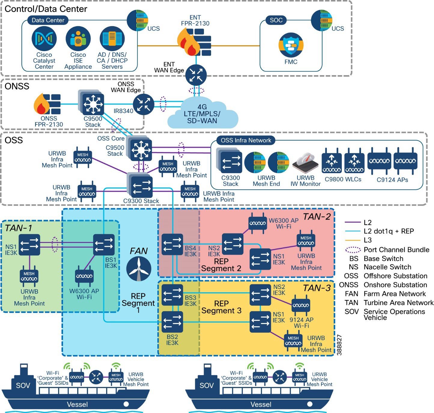
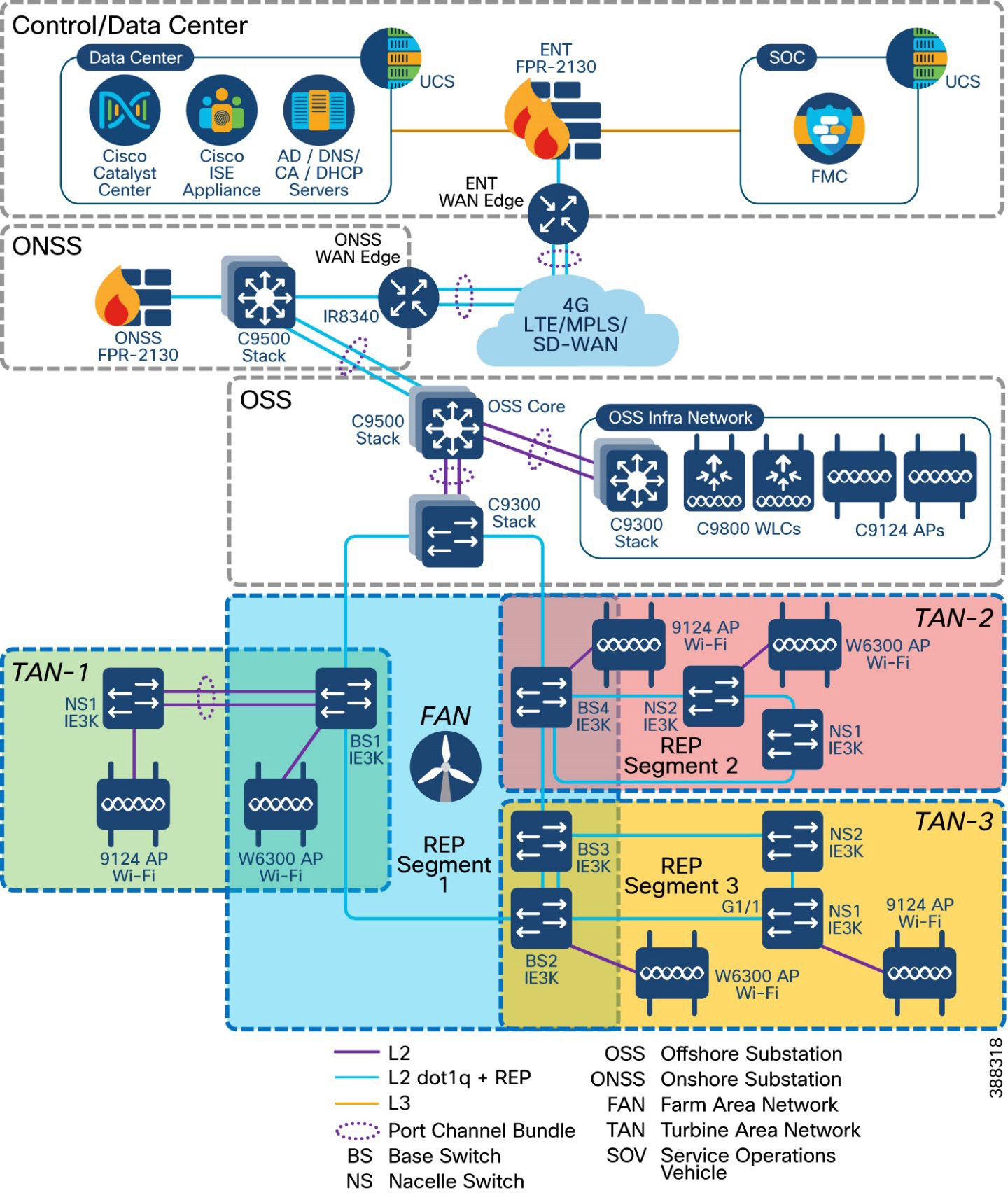
Figure 2 shows the end-to-end solution network architecture of a wind farm.
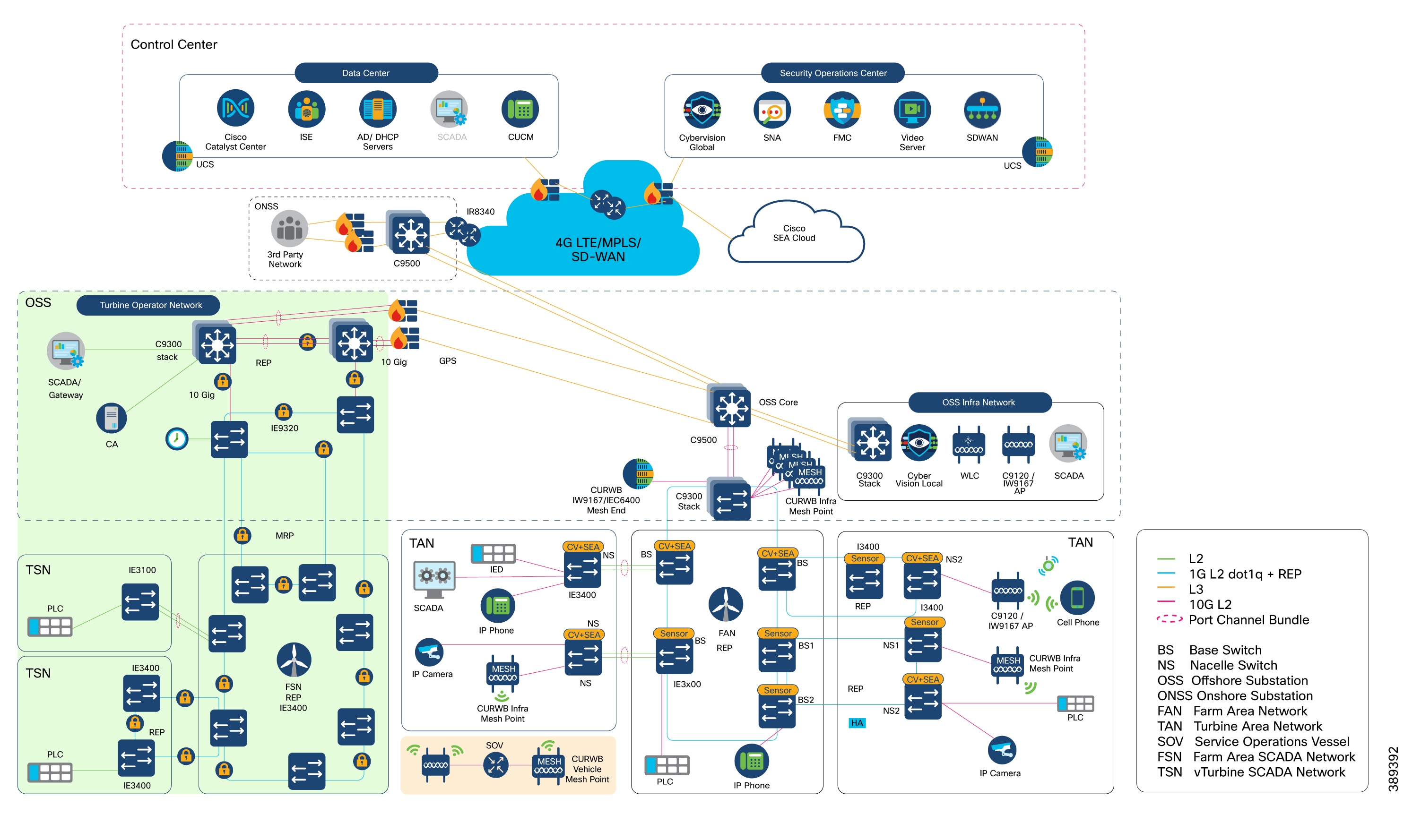
In Figure 2, section highlighted in green is the Turbine Operator Network and new capabilities in an offshore wind Farm, as discussed in the Scope of Wind Farm Release 1.3 CVD.
This section describes the components of a wind farm network. Several device models can be used at each layer of the network. The device models that are suitable for each role in the network and the corresponding CVD software versions are described in Solution Hardware and Software Compatibility.
You can choose a device model to suit specific deployment requirements such as network size, cabling and power options, and access requirements. Table 3 describes device models that are used for components in the architecture for a wind farm solution.
Table 3. Components and Device Models in Wind Farm Architecture
| Component Role |
Component |
Description |
| Turbine nacelle switch, no HA |
Cisco Catalyst Industrial Ethernet (IE) 3400 Series Switch |
1G fiber ring with port channel connectivity to base switch. |
| Turbine nacelle switch, with HA |
Cisco Catalyst Industrial Ethernet (IE) 3400 Series Switch |
1G fiber ring for nacelle switch redundancy. |
| Turbine base switch |
Cisco Catalyst Industrial Ethernet (IE) 3400 Series Switch and/or Cisco Catalyst Industrial Ethernet (IE) 3100 Series Switch |
1G fiber ring for base switches in FAN. Up to 20 switches can be in the ring. 8, 9, or 10 switches in the ring are common in a deployment. |
| Farm area aggregation |
Cisco Catalyst 9300 Series switch Stack |
REP ring aggregation switch. Stack for HA. |
| OSS and ONSS core switch, with HA |
Cisco Catalyst 9500 Series switches with Stackwise Virtual (SVL) |
Offshore IT network core. Deployed with SVL for HA. |
| OSS IT network access switch |
Cisco Catalyst 9300 Series switch stack |
Consists of two switches for HA to provide access connectivity to OSS network infrastructure devices. |
| OSS firewall |
Cisco Secure Firewall 2100 or 4100 Series |
OSS network firewall. |
| ONSS WAN router |
Cisco Catalyst IR8300 Rugged Series Router or Cisco Catalyst 8000 Series Edge Platform |
Onshore substation WAN router |
| OT network sensor |
Combined Cisco Cyber Vision (CV) and Secure Equipment Access (SEA) network sensor on IE3400 Series Switches |
CV network sensors on all IE switches in the ring and FAN. |
| OT security dashboard |
Cisco Cyber Vision Center global and local virtual appliances |
CVC deployed globally and locally in control center and OSS network infrastructures, respectively. |
| Secure Remote Access |
Cisco Secure Equipment Access Cloud |
IoT Operations Dashboard (IoD) hosted in Cisco Cloud for configuring remote access sessions and settings. |
| Wireless LAN controller |
Cisco Catalyst 9800 Wireless Controller (WLC) |
Catalyst Wi-Fi network controller in OSS network infrastructure. |
| SCADA application server |
SCADA application server |
SCADA application server in OSS network infrastructure. |
| URWB gateway |
URWB IW9167E or IEC6400 Edge Compute Appliance |
URWB wireless network mesh end |
| Network management |
Cisco Catalyst Center |
Wind farm network management application in control center and DC. |
| Authentication, authorization, and accounting (AAA) |
Cisco ISE |
AAA and network policy administration. |
| IT and OT security management |
Cisco Secure Network Analytics (Stealthwatch) Manager and Flow Collector Virtual Edition |
Network flow analytics and security dashboard in control center. |
| Physical safety video server |
Cisco or third-party video server for IP cameras |
Cisco or third-party video server for IP cameras in control center |
| 4G-LTE or 5G connectivity for SOV |
Cisco Industrial Router 1101 with 4G-LTE or 5G SIM |
4G-LTE or 5G connectivity for SOV when in range of cellular connectivity close to shore. |
| OSS, FAN, or TAN wireless backhaul |
URWB IW9167E |
URWB infrastructure AP on OSS, FAN, or TAN for SOV wireless backhaul |
| OSS vessel wireless backhaul |
URWB IW9167E |
OSS vessel mesh point for connectivity into OSS or TAN. |
| Wi-Fi network access point |
C9120 AP or IW9167I |
Catalyst Wi-Fi network AP in TAN and OSS. |
| Hardened Wi-Fi access point |
Cisco IW6300 |
Catalyst Wi-Fi network AP in TAN and OSS. |
| Turbine operator SCADA network core switch |
Cisco Catalyst 9300 Series switches |
Consists of two switches in a stack with HSRP for Core network HA. Provides access connectivity to OSS turbine operator SCADA network infrastructure devices. |
| Farm area SCADA Network (FSN) rings aggregation switch |
Cisco Catalyst Industrial Ethernet 9300 Rugged Series switches |
Turbine operator Farm area SCADA network aggregation switch. Also provides 10G uplink core network resiliency using REP and PTP Grandmaster and Boundary Clock (GMC-BC). |
| Farm area SCADA Network (FSN) switch |
Cisco Catalyst Industrial Ethernet (IE) 3400 Series Switch or Cisco Catalyst Industrial Ethernet (IE) 3100 Series Switch |
1G fiber ring for SCADA network base switches in FSN. Up to 20 switches can be in the REP ring or in an MRP ring. |
| Turbine SCADA Network (TSN) switch |
Cisco Catalyst Industrial Ethernet (IE) 3400 Series Switch or Cisco Catalyst Industrial Ethernet (IE) 3100 Series Switch |
Turbine SCADA network nacelle switches in in a HA topology (ring or port channel). |
| Compact ONSS WAN Edge router |
Cisco Catalyst IR1101 Rugged Series Router |
Compact Onshore substation WAN edge router for data center connectivity. |
| Compact ONSS WAN Headend Router |
Cisco Catalyst 8500 Series Edge platform |
Compact Onshore substation data center headend router for FlexVPN tunnels. |
| Compact ONSS Core Switch |
Cisco Catalyst Industrial Ethernet (IE) 3500 Series Switch |
Compact Onshore substation core layer 3 and turbine rings aggregation switch. |
Table 4. Components and Device Models in Wind Farm Architecture
| Component Role |
Hardware Model |
Version |
| Turbine nacelle switch, no HA |
IE3400-8P2S, IE3400-8T2S, IE3100-8T4S |
26.1.1 |
| Turbine nacelle switch, with HA |
IE3400-8P2S, IE3400-8T2S, IE3100-8T4S |
26.1.1 |
| Turbine base switch |
IE3400-8P2S, IE3400-8T2S, IE3100-8T4S |
26.1.1 |
| Farm area aggregation |
C9300-24UX |
26.1.1 |
| OSS core switch, with HA |
C9500-16X |
26.1.1 |
| OSS IT network access switch |
C9300-24UX |
26.1.1 |
| ONSS core switch |
C9300-24UX |
26.1.1 |
| OSS and ONSS DMZ firewall |
Cisco Secure Firewall 2140 |
7.10.1 |
| Firewall management application |
Cisco Secure Firewall Management Center Virtual Appliance |
7.0.1 |
| ONSS WAN edge router |
Cisco Catalyst IR8340 Rugged Series Router |
26.1.1 |
| Network management application |
Cisco Catalyst Center Appliance DN2-HW-APL |
2.3.6.0 |
| Unified Computing System (UCS) |
UCS-C240-M5S |
3.1.3c |
| AAA server |
Cisco ISE Virtual Appliance |
3.2 |
| CV network sensors |
IoX Sensor App |
5.04.0 |
| OT security dashboard |
Cisco Cyber Vision Center global and local virtual appliance |
5.04.0 |
| Wireless LAN controller |
C9800-L-C-K9 |
26.1.1 |
| Cisco IW6300 ruggedized AP for Wi-Fi access |
IW6300-AP |
26.1.1 |
| Cisco AP for Wi-Fi access |
AIR-AP9120 or IW9167 |
26.1.1 |
| URWB mesh point |
URWB IW9167E |
26.1.1 |
| URWB mesh gateway |
URWB IW9167E or IEC6400 |
26.1.1 |
| URWB IW-Monitor |
URWB IW-Monitor VM |
v2.0 |
| IT and OT security management |
Cisco Secure Network Analytics (Stealthwatch) Manager and Flow Collector Virtual Edition |
7.4.1 |
| Control center headend router |
ASR-1002-HX |
17.3.4a |
| WAN management |
Cisco SD-WAN Manager, SD-WAN Validator virtual appliances |
20.8.1 |
Table 5. Turbine Operator Network Cisco Hardware and Software versions Validated in this CVD
| Component Role |
Hardware Model |
Version |
| Turbine Operator network core switch |
C9300-24UX |
26.1.1 |
| Farm area SCADA network rings aggregation switch |
IE-9320-22S2C4X |
26.1.1 |
| Turbine SCADA switch, no HA |
IE3400-8P2S IE3400-8T2S IE3100-8T4S |
26.1.1 |
| Turbine SCADA switch, with HA |
IE3400-8P2S IE3400-8T2S IE3100-8T4S |
26.1.1 |
| Turbine base switch in FSN |
IE3400-8P2S, IE3400-8T2S IE3100-8T4S |
26.1.1 |
| Compact Onshore Substation WAN edge router |
IR1101-K9 |
26.1.1 |
| Compact Onshore Substation Headend router |
C8500-12X |
17.15.1a |
| Compact Onshore Substation Core Switch |
IE3500-8P3S |
26.1.1 |
Table 6. Third-party Hardware and Software Versions Validated in this CVD
| Component Role |
Hardware Model |
Version |
| Turbine physical security (CCTV) camera |
AXIS P3717-PLE |
10.3.0 |
| Video server for CCTV camera |
Axis Device Manager (ADM) |
5.9.42 |
| CA, AD, DHCP, and DNS servers in control center |
Microsoft Windows 2016 Server |
Windows 2016 Server Edition |
Solution Design Considerations
This chapter includes the following topics:
● Turbine Base Switch Network Design
● Offshore Substation Network and Building Blocks
● Network VLANs and Routing Design
● SCADA Applications and Protocols
● Turbine Operator Network Design
In offshore wind farms, each wind turbine has a Cisco IE3400 switch deployed at the turbine nacelle to provide offshore substation (OSS) network connectivity to various endpoints in the turbine. These endpoints include SCADA devices, PLC, I/O devices, CCTV cameras, and so on. The IE switch deployed in the turbine nacelle is also called a nacelle switch (NS). The NS with its OT and IT endpoints forms a turbine area network (TAN) in the wind farm solution architecture, as shown in Figure 3.
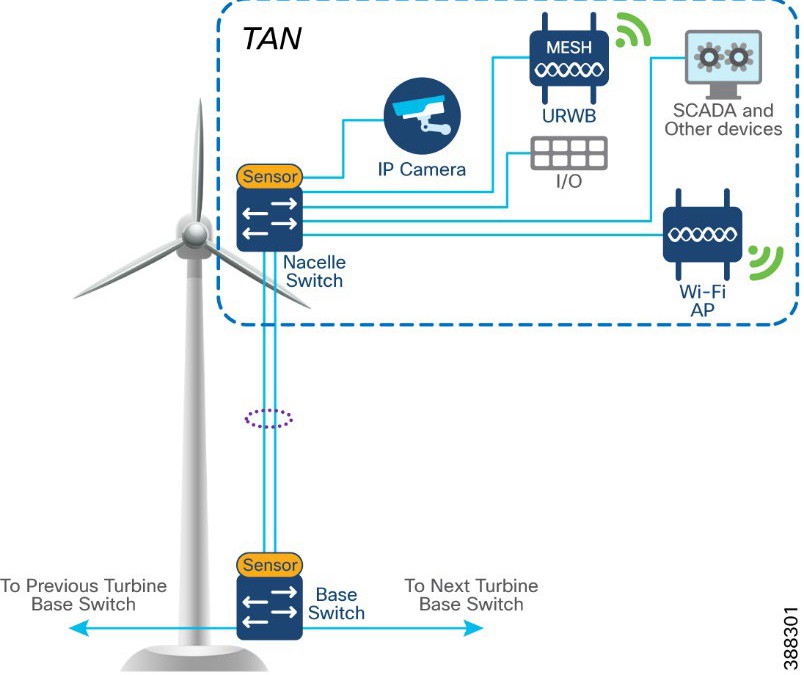 |
Table 7 lists the actors and traffic types in a TAN.
Table 7. TAN Actors and Traffic Types
| Actors |
Traffic Type |
| CCTV camera |
TAN to control center. CCTV camera in nacelle switch streaming live video to video server in OSS infrastructure or control center. |
| PLC and IO |
Traffic within the TAN. OT Traffic between PLC and I/O in nacelle. TAN to base. PLC in base of turbine to I/O in nacelle. |
| Wi-Fi access point |
TAN to OSS infrastructure and CC. Workforce AP in Nacelle to WLC in OSS network. Provides corporate network access and guest internet access. |
| SCADA |
TAN to OSS infrastructure. management traffic between SCADA endpoints in OSS. |
| URWB |
Offshore vessel wireless connectivity using URWB network from the TAN. |
TAN Non-HA Design Considerations
● Single Cisco IE3400 switch deployed in each turbine nacelle, as shown in Figure 4 for the TAN non-HA design option turbine nacelle Ethernet switch.
● Layer 2 Star Topology (non-HA) of nacelle switches connecting to turbine base switch (shown in Figure 4).
● An LACP port-channel with two member links to a base switch provides link-level redundancy to TAN.
● Multiple VLANs for segmenting TAN devices are configured in the NS. Examples include CCTV camera VLAN, OT VLAN for SCADA endpoints, Wi-Fi AP management VLAN, management VLAN (FTP/SSH), URWB VLAN for vessel connectivity, voice VLAN for VOIP phones, and marine systems VLAN.
● First hop security protocols with device authentication using MAB or Dot1x are configured for securing TAN endpoints.
● Layer 3 gateway for all VLANs in the NS is configured in OSS Core switch (C9500 switch)
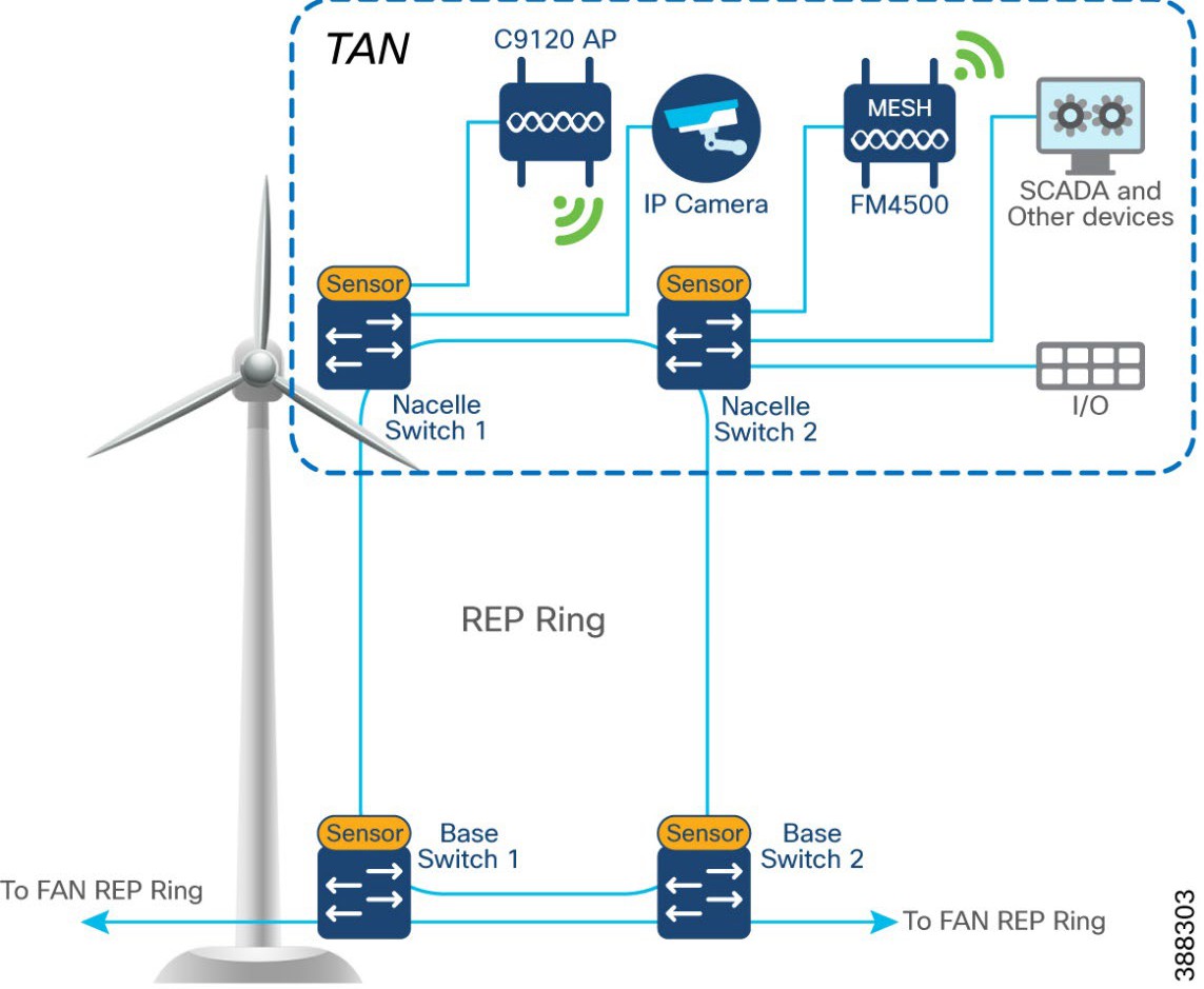
TAN High Availability Design with REP
An IE3400 nacelle switch in the TAN provides a single point of failure for TAN endpoints. To provide a highly available TAN, two nacelle switches are deployed for TAN endpoints network connectivity. In addition, a redundancy protocol is configured.
Resilient Ethernet Protocol Ring
Resilient Ethernet Protocol (REP) is a Cisco proprietary protocol that provides an alternative to Spanning Tree Protocol (STP) for controlling network loops, handling link failures, and improving convergence time. REP controls a group of ports that are connected in a segment, ensures that the segment does not create bridging loops, and responds to link failures within the segment. REP provides a basis for constructing complex networks and supports VLAN load balancing. It is the preferred resiliency protocol for IoT applications.
A REP segment is a chain of ports that are connected to each other and configured with a segment ID. Each segment consists of standard (non-edge) segment ports and two user-configured edge ports. The preferred alternate port selected by REP is blocked during normal operation of the ring. If a REP segment fails, the preferred alternate port is automatically enabled by REP, which provides an alternate path for the failed segment. When the failed REP segment recovers, the recovered segment is made the preferred alternate port and blocked by REP. In this way, recovery happens with minimal convergence time.
Two uplink ports from two nacelle switches deployed for HA in TAN are connected to a turbine base switch.
There are two options for TAN high availability design. In the first option, shown in Figure 4, a closed ring topology of two nacelle switches connects to a single turbine base switch. This arrangement forms a subtended REP ring to the FAN main ring.
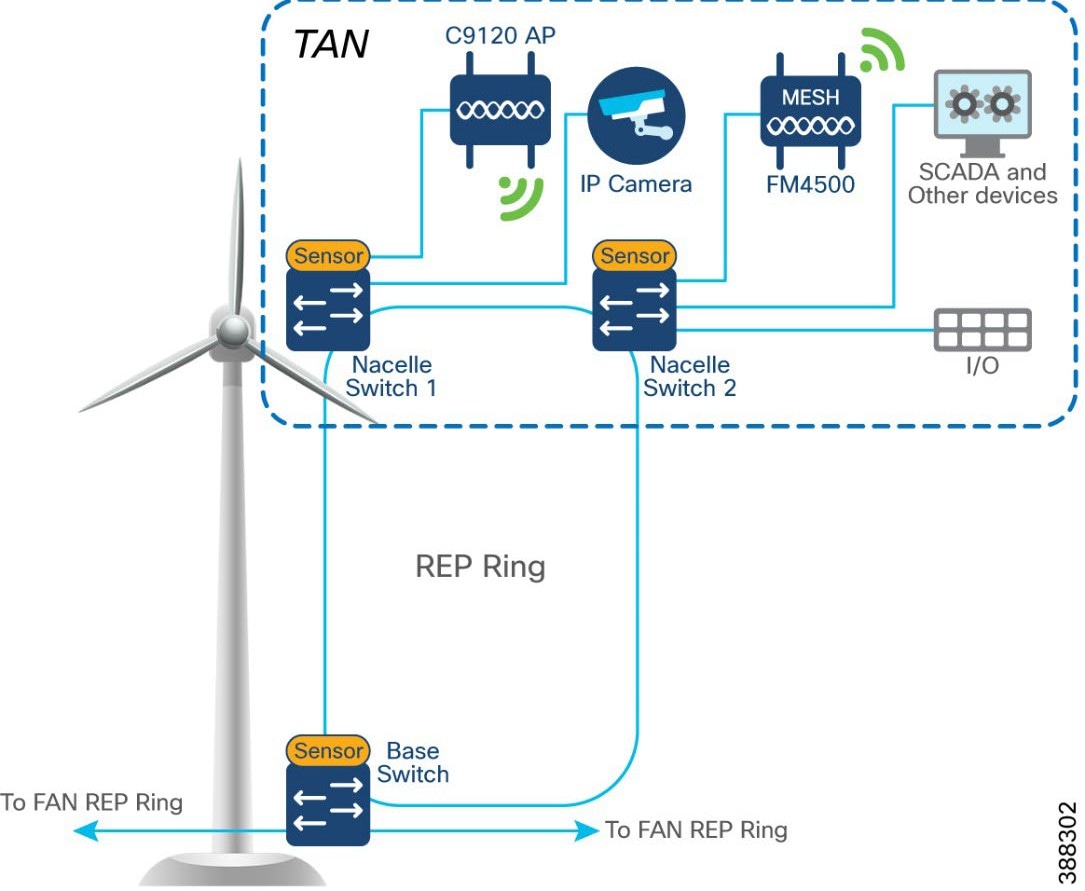 |
In the second option, shown in Figure 5, the uplinks form two nacelle switches are connected to two different base switches in a TAN, which provides redundancy for the turbine base switch network and the TAN. In this option:
● An open ring topology of two nacelle switches connects to two turbine base switches.
● A subtended RIP ring of FAN main REP ring of base switches is formed.
 |
In offshore wind farms, each wind turbine has an IE3400 switch that is deployed at the turbine base to provide OSS network connectivity to various endpoints in the turbine base. These endpoints include SCADA devices, PLC, I/O devices, CCTV cameras. the TAN, and so on. The IE switch that is deployed in the turbine base is also called the base switch (BS). The BS, with its OT and IT endpoints, forms a Turbine Base Network (TBN) in the wind farm solution architecture, as shown in Figure 6.
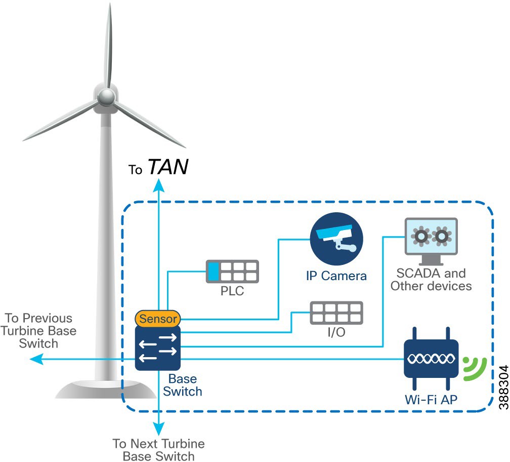 |
Table 8 lists the actors and traffic type in a turbine base switch network.
Table 8. Turbine Base Network Actors and Traffic Types
| Actors |
Traffic Type |
| CCTV camera |
Base to control center. CCTV camera in base switch streaming live video to video server in OSS infrastructure or control center. |
| PLC and I/O controller |
Traffic within base. OT traffic between PLC and I/O in base. Base to base. PLC in base of turbine to I/O in base. |
| Wi-Fi access point |
Base to OSS infrastructure or control center. Workforce AP in base switch communicating with the WLC in the OSS infrastructure. Provides connectivity to the OSS and DC network based on needs and provides guest internet access. |
| SCADA |
Base to OSS Infrastructure. Management traffic between SCADA endpoints in OSS. |
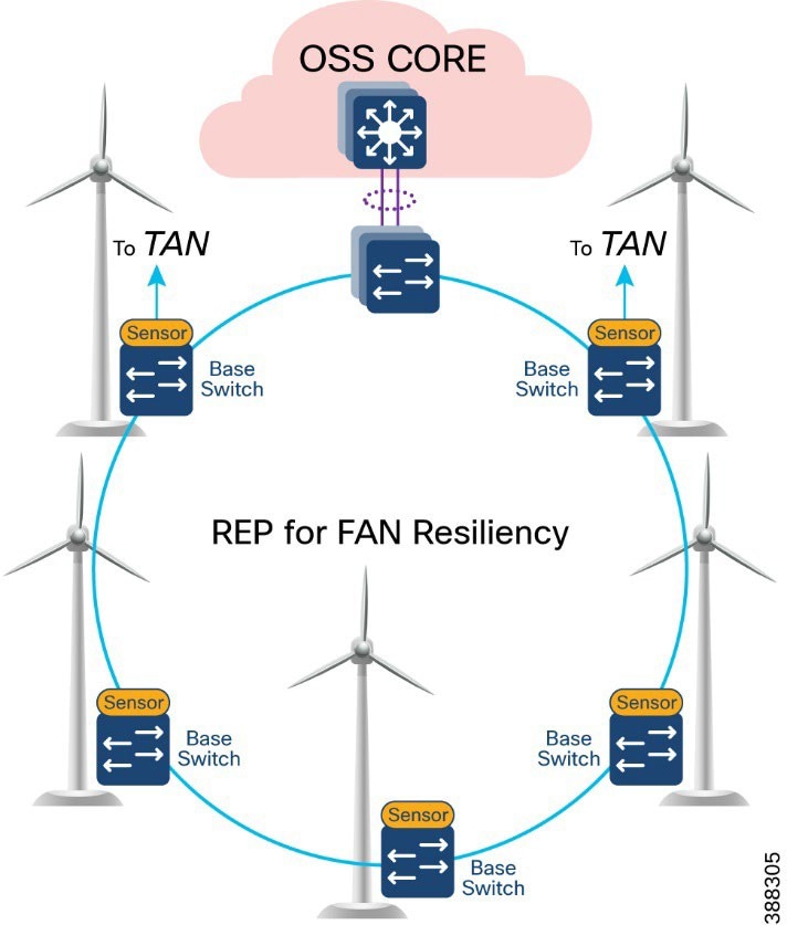
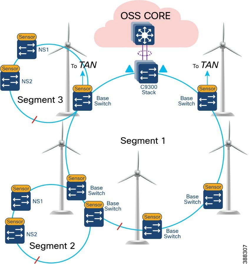
In offshore wind farms, the base switch from each wind turbine is connected in a ring topology using a 1G fiber cable with Catalyst 9300 stack switches to form a farm area network (FAN) ring. A REP is configured in the FAN ring to provide FAN resiliency for faster network convergence if a REP segment fails.
Figure 7 shows a FAN ring aggregating to a pair of Cisco Catalyst 9300 switches in a stack configuration. A Catalyst 9300 stack aggregates all FAN rings in an offshore wind farm.
 |
● Cisco Industrial Ethernet 3400 Switches as turbine base ethernet switches.
● A layer 2 closed ring of turbine base switches connected via 1G fiber forms a FAN.
● FAN base switches aggregate subtended REP ring for HA traffic from the TAN with HA.
● A FAN ring consists of a maximum of 18 base switches. A Catalyst 9300 stack aggregates up to 10 FAN rings, depending on the Catalyst9300 model and port density.
● REP protocol is used for base switches and FAN resiliency; REP edge ports are configured on a Catalyst 9300 stack in OSS aggregation.
● Multiple VLANs are configured for network segmentation of TAN and FAN devices. Examples include CCTV camera VLAN, OT VLAN for SCADA endpoints, management VLAN (FTP and SSH), URWB VLAN for vessel connectivity, Wi-Fi AP management VLAN, voice VLAN for VoIP Phones, and marine systems VLAN.
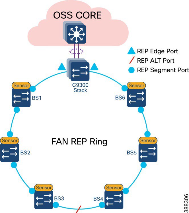
A closed REP ring of FAN forms a main REP segment to forward all VLAN traffic in an offshore wind farm network. Primary and secondary REP edge ports are configured on an OSS aggregation switch stack (Catalyst9300) and an alternate port is configured in the middle of the ring. See Figure 8.
A FAN REP ring can be provisioned by using the Cisco Catalyst Center REP workflow, which automates the REP configuration from daisy-chained IE switches. For more detailed information about FAN REP ring and subtended REP ring provisioning using Cisco Catalyst Center, see Chapter 5: Network Management and Automation.
 |
A TAN REP ring aggregating to a turbine base switch or a pair of base switches, as discussed in TAN High Availability Design with REP, creates a subtended REP ring or ring of REP rings in an offshore wind farm network. A closed or open REP ring configured with REP Topology Change Notification (TCN) within a REP segment notifies REP neighbors of any topology changes. At the edge, REP can propagate the TCN to other REP segments.
Figure 9 shows the FAN main REP ring and subtended REP rings design in the wind farm solution architecture.
 |
An offshore wind farm can have more than 200 turbines, and each turbine can have more than 2 base switches that connect to the OSS network. We recommend that a deployment have a FAN ring size of more than 20 IE switches. Multiple such FAN rings should be aggregated to access offshore substation (OSS) and onshore substation (ONSS) IT networks.
The FAN aggregation infrastructure is composed of Cisco Catalyst 9300 Series switches, typically with two of these switches in a physical stack, that are capable of providing 10G uplinks to OSS and ONSS networks. A stack of two Catalyst 9300 switches physically located in an OSS network connects turbine base switches in a ring via fiber cables (turbine string cables) and aggregates layer 2 traffic from each ring to upper layers of the wind farm network infrastructure, for or example, to an OSS core switch.
Figure 10 shows the FAN aggregation design using a stack of Catalyst 9300 Series switches to aggregate FAN rings and their traffic from and to offshore wind turbines.
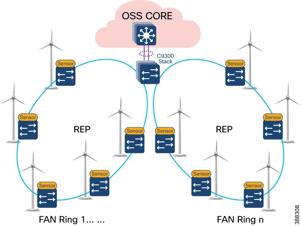 |
We recommend that between one and nine FAN rings be aggregated to a stack of Catalyst 9300 switches for optimal network performance. If there are more than 200 turbines or base switches in a wind farm, another stack of two Catalyst 9300 switches can be added to the FAN aggregation network in the offshore substation OSS.
Offshore Substation Network and Building Blocks
This section discusses the design for a wind farm OSS network. The OSS network has following building blocks:
● OSS core network: Provides network layer 3 routing across offshore and onshore substations
● OSS DMZ and third-party or other networks: Provides secure remote access for corporate employees and third-party vendors to OSS assets
● OSS infrastructure network: Hosts OSS infrastructure services and application servers
An offshore substation core network is composed of a pair of suitably sized layer 3 devices that provide resilient core networking and routing capabilities. Multilayer switches may be used as core switches, even though they are intended for routing. In the wind farm solution architecture, Cisco Catalyst 9500 Stackwise Virtual (SVL) switches are used as OSS core network switches.
The OSS core connects to multiple components, and this connection should be resilient, providing higher bandwidth (10Gbps) layer 3 links. The OSS core network connects the following building blocks in an OSS network and provides connectivity through fiber uplinks to the onshore substation network (ONSS), as shown in Figure 11.
● ONSS network: Connects to ONSS core switches.
● OSS infrastructure network: Provides layer 2 access switch connectivity to infrastructure applications such as CVC, SCADA servers, WLC, and so on.
● FAN aggregation: Aggregates FAN rings in a wind farm
● OSS DMZ and firewall: Connects to third-party networks (for example, turbine vendor SCADA networks such as GE, VESTAS, and others, and substation automation networks export cable HVDC and AC systems).
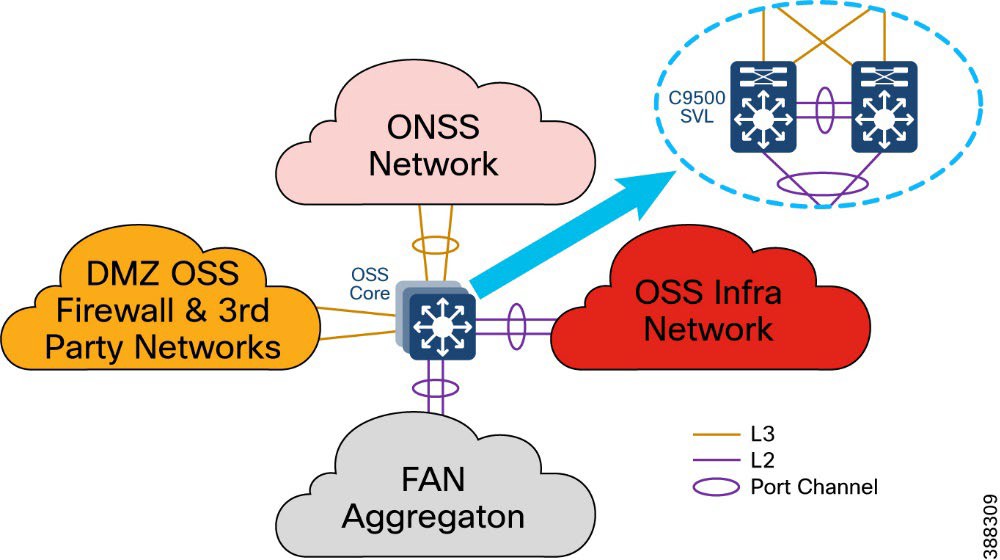 |
In Figure 11, a pair of Cisco Catalyst 9500 switches in Stackwise Virtual (SVL) configuration provides core network high availability across OSS networks with layer 3 links to the OSS DMZ firewall and ONSS core. These layer 3 links can be configured as Equal-Cost Multi Pathing (ECMP) routing links or links bundled in a layer 3 port channel.
The C9500 SVL switch connects to the OSS infrastructure and FAN aggregation switches using layer 2 port channels with each port channel bundling two 10 Gb ethernet interfaces.
OSS DMZ and Third-Party Network
A DMZ in a wind farm OSS network provides a layer of security for the internal network by terminating externally connected services at the DMZ and allowing only permitted services to reach the internal network nodes.
Any network service that runs as a server that communicates with an external network or the Internet is a candidate for placement in the DMZ. Alternatively, these servers can be placed in a data center and be reachable only from the external network after being quarantined at the DMZ.
Cisco Next-Generation Firewall (NGFW) is deployed with outside interface connectivity to third-party turbine vendor networks and inside interface connectivity to the OSS core network, as shown in Figure 12. A Cisco Secure Firewall Management Center in the control center centrally manages all Cisco Secure Firewall instances in the OSS and ONSS networks.
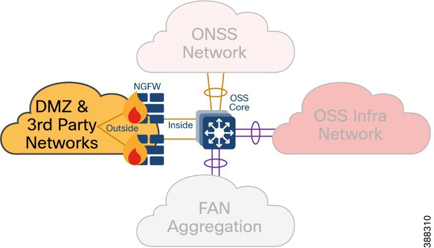 |
The OSS DMZ is composed of a resilient pair of Cisco NGFW Secure Firewall 2100 or 4100 Series appliances. The Cisco Secure Firewall in OSS DMZ provides OSS network security protection from outside vendor networks.
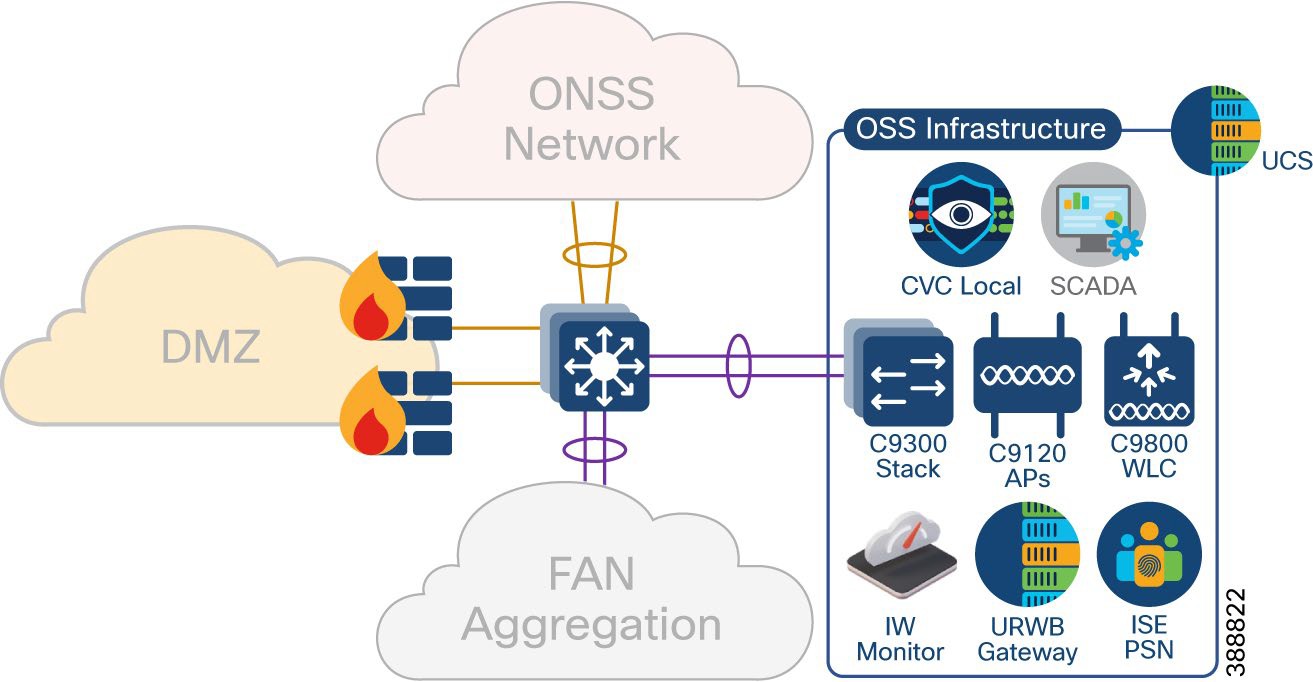
This section covers various infrastructure components and application servers in a wind farm network. The OSS infrastructure is composed of a set of resources that are accessible by devices or endpoints across the FAN and TAN. The OSS infrastructure is deployed with a pair of Cisco Catalyst 9300 Series switches in a stack to extend access to various applications and servers, as shown in Figure 13 as Option 1.
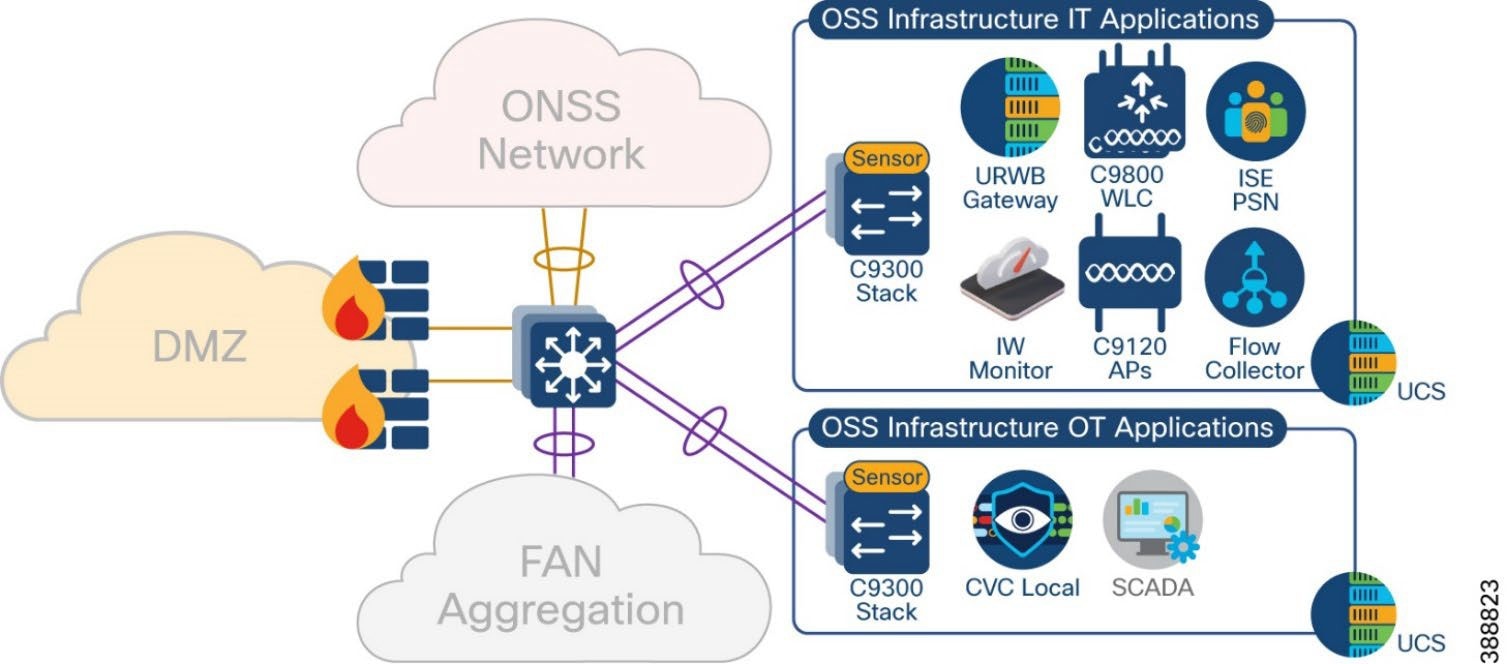
You also can deploy the OSS infrastructure with a separate access switch stack and UCS server for wind farm OSS IT and OT applications respectively, as shown in Figure 13 as Option 2. The OSS infrastructure includes of:
● One or more Cisco Unified Computing System (UCS) servers for hosting virtual machines for the applications
● On Cisco Cyber Vision Center (CVC) Local
● One or more ISE PSNs*
● Two URWB gateways (IW9167E or IEC6400)
● Two Catalyst 9800 WLCs
● Four IW9167E devices with 90-degree horn antennas
● IW6300 or C9120 APs for Wi-Fi access
● One URWB IW monitor
● SCADA server application
Figure 13 shows the wind farm OSS infrastructure network and its components.
 |
*ISE PSN may optionally be deployed at the OSS infrastructure network for the distributed deployment of ISE with PAN at the control center. You also may choose to decentralize PSNs if there is a latency concern.
Figure 14 shows the wind Farm OSS Infrastructure network option for IT and OT applications separated into two access switch stacks and UCS servers.
 |
In a wind farm network, an onshore substation (ONSS) is a renewable energy site that is normally in remote areas where communication network is not readily available.
Generally, offshore substations connect to ONSSs in rural locations where access to backhaul technologies is limited. While offshore to onshore connectivity is served by fiber optic cable, the backhaul from the onshore location is more challenging and often relies on service provider network availability for services such as fiber, MPLS, metro Ethernet, and so on.
In the wind farm solution architecture, Cisco Catalyst 9500 Stackwise Virtual (SVL) switches are used as ONSS core network switches. The ONSS core connects to multiple components. The connections should be resilient and provide higher bandwidth (10Gbps) and layer 3 links for scalable L3 routing.
Figure 15 shows the building blocks in an ONSS network that the ONSS core network connects to.
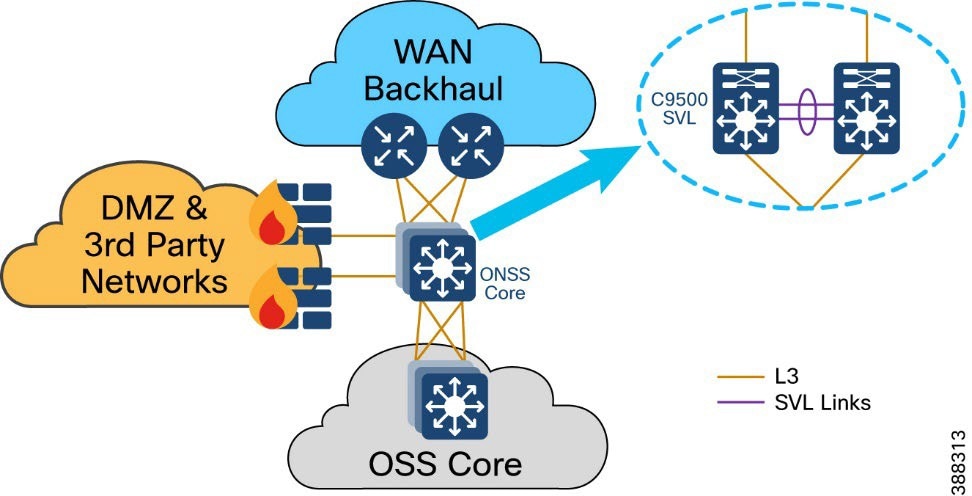 |
OSS network building blocks include:
● OSS network: Connects to an OSS core switch via 10 Gb fiber links
● ONSS DMZ and firewall: Connects to third-party networks (for example, turbine vendor SCADA network, power control and metering network, export cable HVAC and DC system)
● WAN backhaul: Connects wind farm data center and control center to the ONSS via service provider MPLS, 4G LTE, and so on.
The ONSS DMZ is similar to the OSS DMZ that is discussed in OSS DMZ and Third-Party Network. WAN backhaul and control center are discussed in detail in the following section.
This section discusses wind farm WAN backhaul connectivity in an onshore substation. The wind farm WAN often is a dedicated WAN infrastructure that connects the transmission service operator (TSO) control center with various substations and other field networks and assets. Wind farm WAN connections can include a variety of technologies, such as cellular LTE or 5G options for public backhaul, fiber ports to connect wind farm operator or utility owned private networks, leased lines or MPLS PE connectivity options, and legacy multilink PPP backhaul aggregating multiple T1/E1 circuits.
ONSS WAN router can provide inline firewall (zone-based firewall) functionality, or a dedicated firewall can be placed beyond the substation router to protect wind farm assets. This approach results in a unique design in which a DMZ is required at the substation edge. All communications into and out of the substations network must pass through the DMZ firewall. The zone traffic egressing the substation edge should be encrypted using IPsec and put into separate logical networks using Layer 3 virtual private network (L3VPN) technology, as shown in Figure 16.
A WAN tier aggregates the wind farm operator’s control center and onshore and offshore substations. A Cisco IR8340 or C8000 Series Router deployed as an ONSS WAN edge router serves as an interface between the onshore substation and the control center.
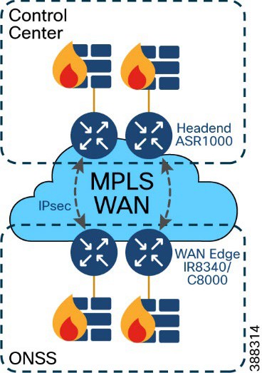 |
WAN circuits and backhaul failure options are efficiently designed, provisioned, and managed using Cisco SD-WAN.
For more information, see Cisco SD-WAN Design Guide.
The wind farm WAN backhaul design is similar to the Cisco Substation Automation Solution WAN backhaul design. For more information about WAN backhaul design, see Substation Automation Design Guide – The New Digital Substation.
A wind farm asset operator’s control center hosts multiple IT and OT applications with other network infrastructure servers. All communications to the control center are secured by using a pair of firewalls in HA deployment and a pair of Cisco ASR1000 series routers acting as headend or hub routers. Cisco ASR1000 Series routers terminate all IPSec tunnels from remote substations WAN edge routers.
Figure 17 shows a wind farm control center with its IT and OT applications and servers.
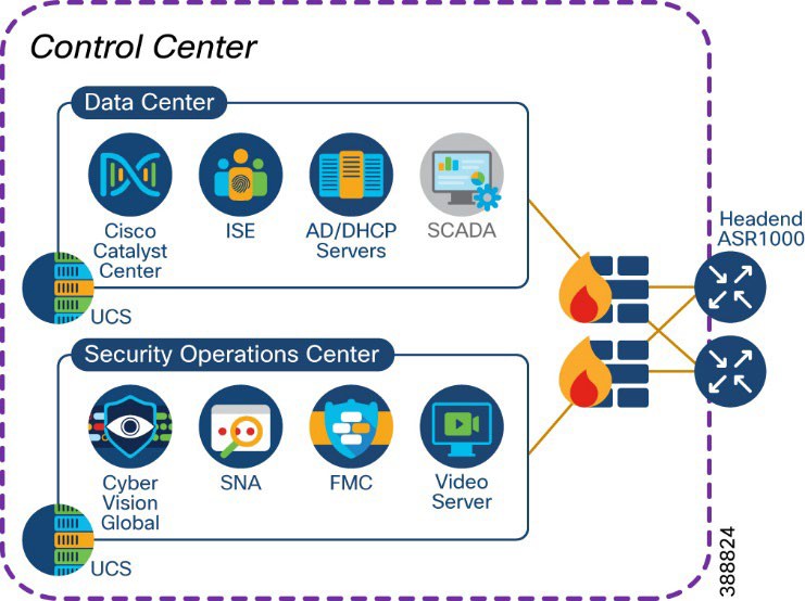 |
The control center network consists of:
● One or more Cisco ASR1000 Series routers for WAN headend
● One or more 2100 or 4100 Series firewalls
● One or more Cisco Unified Computing System (UCS) servers for hosting virtual machines for applications
● One Cisco Catalyst Center for network management
● One or more Cisco ISE policy administration node (PAN)*
● One centralized Active Directory
● One centralized DHCP server
● One network time protocol (NTP) server
● One SCADA server application for wind farm turbine control
● One video server for CCTV
● One Cyber Vision Global
● One Cisco Centralized Secure Firewall Management Center
● One Cisco Secure Networks Analytics Manager (SMC)
* PSN may optionally be deployed at the OSS Infrastructure network for the distributed deployment of ISE with the
PAN located at the control center. You may also choose to decentralize the PSN whenever there is a concern about latency.
Network VLANs and Routing Design
This section covers the different VLANs in a wind farm network and virtual routing and forwarding (VRF) for layer 3 routing between OSS and ONSS core networks. The wind farm network is segmented by using VLANs for various endpoints and applications traffic. There is a dedicated VLAN and VRF for each service, endpoint, or application traffic in the network. Table 9 summarizes the design guidance for creating multiple VRFs and VLANs in the network.
Table 9. VLANs and VRFs in the Wind Farm Network Design
| VRF |
VLAN Description |
| Management VRF (VRF for network management traffic) |
Network device management VLAN(s) Wi-Fi and URWB aps management VLAN(s) FAN and TAN REP ring administrative VLAN(s) Cyber Vision (CV) collection network VLAN(s) |
| Video and voice VRF (VRF for CCTV cameras and IP telephony voice traffic) |
VLANs for CCTV Cameras in FAN and TAN IP telephony devices voice VLAN |
| Wi-Fi access VRF |
Employee and contractor Wi-Fi access VLAN Guest Wi-Fi access VLAN |
| URWB traffic VRF |
URWB traffic VLAN |
| Operational technology (OT) (VRF for all renewables and OT traffic in the network) |
VLANs for SCADA traffic such as weather systems, HVAC, fire detection, lightning detection, and other systems such as wildlife monitoring VLANs for automation systems such as I/O controllers, PLCs, and so on |
| Internet VRF (VRF for device Internet access from the wind farm network) |
DMZ VLANs for Internet traffic routing in OSS and ONSS networks |
| Global routing table (GRT) |
VLANs local to OSS network (not to be routed) VLANs local to ONSS network (not to be routed) |
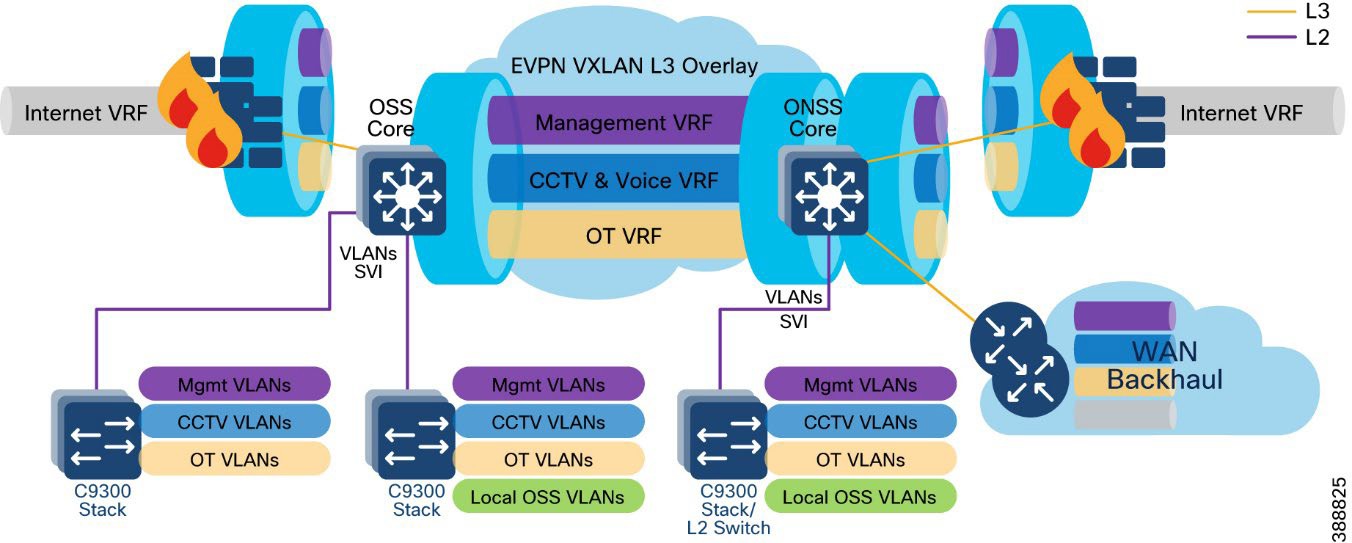
A VRF creates a separate routing and forwarding table in the network for IP routing, which is used instead of a default global routing table (GRT). A VRF provides high-level network segmentation across multiple services or traffic in the network. Each VLAN layer 3 interface (SVI) is created and assigned to a VRF for layer 3 routing in the OSS and ONSS core switches.
The VRF-lite feature is used along with Ethernet VPN - Virtual Extensible LAN (EVPN-VXLAN) design to provide a unified overlay network solution for layer 3 routing between OSS and ONSS core Catalyst 9500 Stackwise Virtual (SVL) switches per VRF. This provides a more scalable solution for traffic segregation (per VRF) while using a single control plane routing protocol to exchange VRF prefixes (BGP).
Figure 18 illustrates the layer 3 IP routing design in the wind farm architecture.
 |
For more information, see Information about VRF-lite in IP Routing Configuration Guide, Cisco IOS XE Dublin 17.10.x (Catalyst 9500 Switches).
Ethernet VPN (EVPN) is a control plane for VXLAN that is used to reduce the flooding in the network and address scalability challenges in a VXLAN network due to flood and learn mechanism. To address this issue, a control plane is used to manage the MAC address learning and Virtual Tunneling End Point (VTEP) discovery. In BGP EVPN VXLAN deployments, Ethernet Virtual Private Network (EVPN) is used as the control plane. EVPN control plane provides the capability to exchange both MAC address and IP address information. EVPN uses Multi-Protocol Border Gateway Protocol (MP-BGP) as the routing protocol to distribute reachability information pertaining to the VXLAN overlay network, including endpoint MAC addresses, endpoint IP addresses, and subnet reachability information.Refer to the following URL for more details on BGP EVPN VXLAN design.
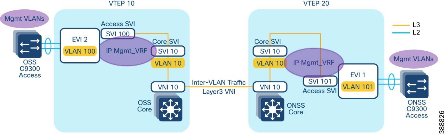
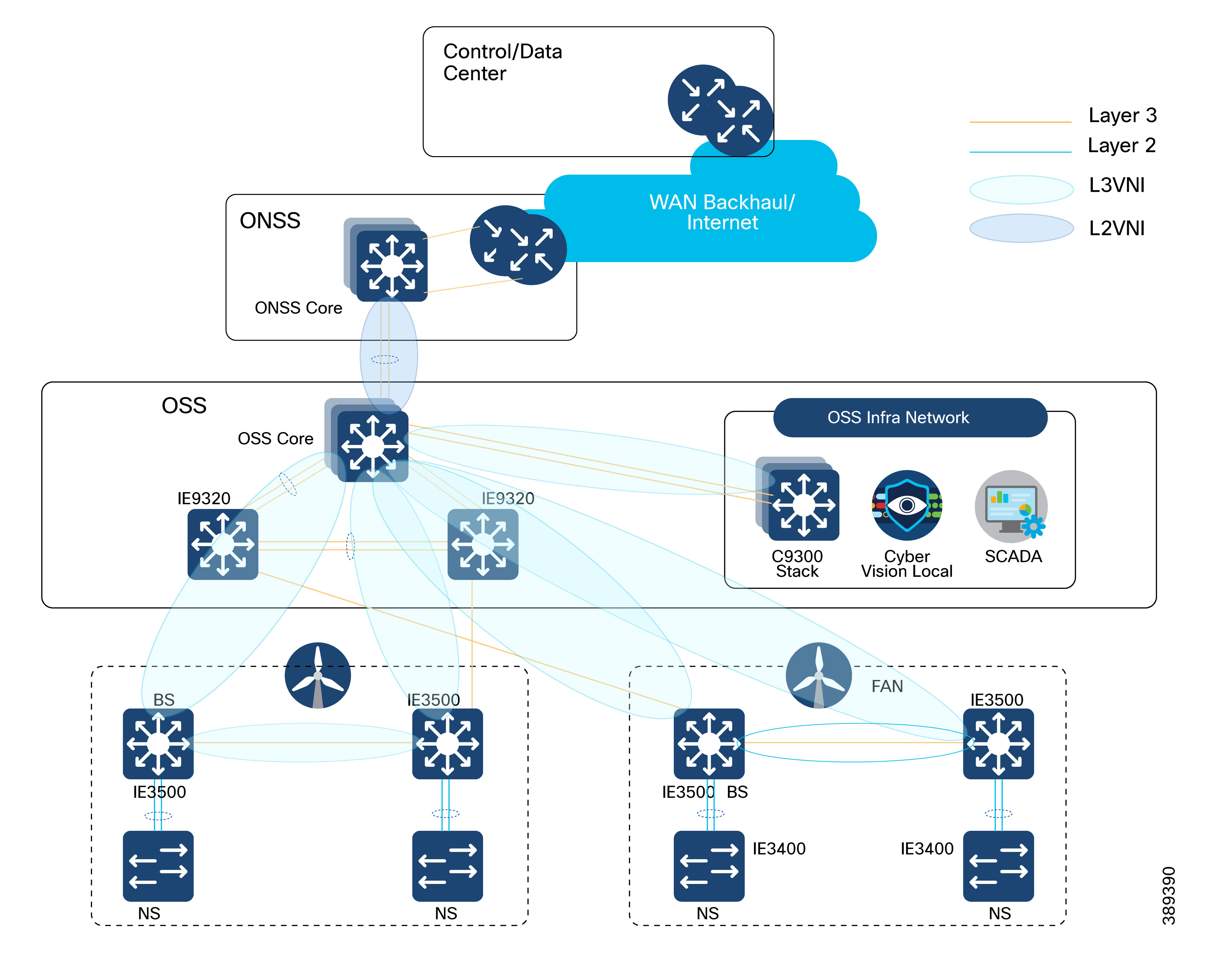
An EVPN VXLAN Layer 3 overlay network allows host devices in different Layer 2 networks to send Layer 3 or routed traffic to each other. The network forwards the routed traffic using a Layer 3 virtual network instance (VNI) and an IP VRF. In the Wind Farm Asset operator’s offshore and onshore substations (OSS & ONSS) core networks are configured in a two VTEP topology without a spine switch, as shown in Figure 19.
In this design, a layer 3 overlay VXLAN network between OSS and ONSS core switches is configured per VRF (with BGP routing) to route inter-subnet traffic between these core switches using layer 3 Virtual Network Identifier (L3VNI). A Layer 3 VNI and a VTEP is configured per VRF in the wind farm network. The following Figure 19 shows the movement of traffic in an EVPN VXLAN Layer 3 overlay network using a Layer 3 VNI for a VRF in the wind farm network.
 |
Refer to the following URL for more information about EVPN VXLAN Layer 3 overlay network.
BGP EVPN VXLAN Network Design for Turbine Network
Alternative to Layer 2 switching network design for the wind farm operator’s turbine network, Layer 3 based BGP EVPN VXLAN network provides following benefits.
● Eliminates Layer 2 domain with REP in FAN ring
● Provides deterministic Layer-3 transport
● Enables a scalable fabric based L2 extension (overlay) between turbines and OSS core
● Provides VRF-based network segmentation
● Ensures fast convergence (sub-second target)
● Provides operational clarity for field troubleshooting
This section describes BGP EVPN VXLAN based network design option for wind farm operator’s turbine network which can be preferred over a layer 2 turbine network design depending on the wind turbine deployments and ease of operations required.
Turbine network Underlay Design
An underlay network is the physical network over which the virtual overlay network is established. Once the overlay network is defined along with the data-plane encapsulation, a method of transport is required to move the data across the physical network underneath. This method of transport is typically an underlay transport network, or simply the underlay.
In BGP EVPN VXLAN, the underlay Layer 3 network transports the VXLAN-encapsulated packets between the source and destination VTEPs and provides reachability between them. The VXLAN overlay and the underlying IP network between the VTEPs are independent of each other.
The underlay network for BGP EVPN VXLAN is a routed inter-switch links between turbine base and OSS aggregation switches. This provides a deterministic L3 fault domains in the FAN ring (fast reconvergence, scalable routing), while keeping the nacelle/base access simple and rugged.
Figure 20 illustrates the underlay physical network design for the turbine network.
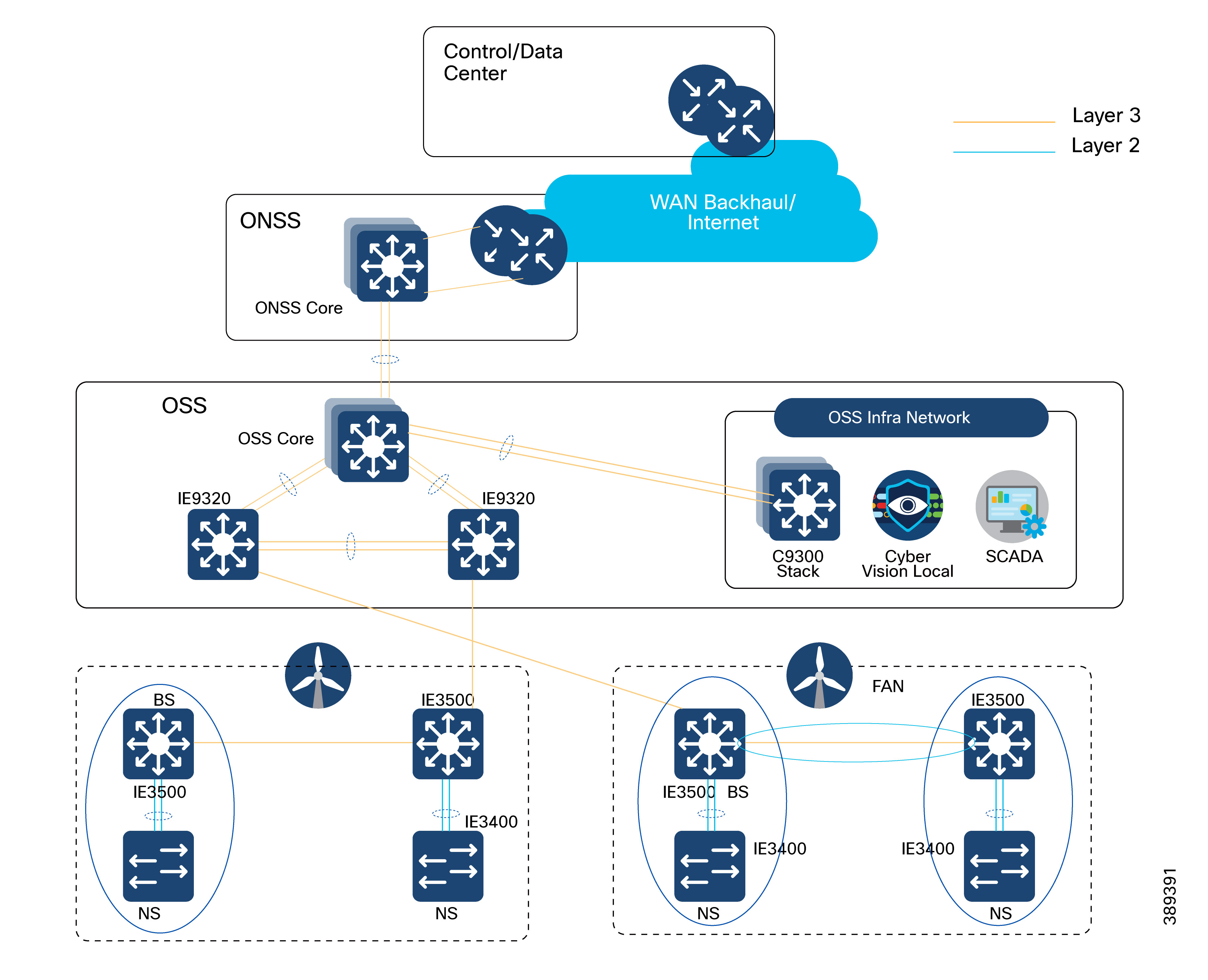 |
As shown in Figure 20, following are the underlay network design considerations for the turbine network, to deploy a BGP EVPN VXLAN overlay network across OSS and turbine switches.
Turbine Base Switches (IE3500) as L3-connected leaf sites: Each turbine base switch participates in the L3 Farm Area Network (FAN) ring toward the aggregation layer.
It is recommended to connect two turbine base switches per FAN ring
Ring Aggregation Switches (IE9320) as L3 transit in a redundant pair:
1. Deploy IE9320s as a pair with an L3 Port-Channel between them (east-west redundancy)
2. Uplink that IE9320 pair to OSS Core (C9500 SVL) using L3 Port-Channels for underlay redundancy
OSPF as underlay routing protocol to provide network reachability between OSS core, OSS aggregation (IE9320) and turbine base switches with consistent MTU across OSPF domain. It is recommended to configure a physical MTU size of 9198 bytes in all switches participating in the BGP EVPN VXLAN overlay fabric.
Turbine Nacelle Switches (IE3400) stay L2-attached to the base: Use Layer-2 Port-Channel from IE3400 (nacelle) to IE3500 (base) for access resiliency while keeping the FAN ring purely L3.
Turbine network VXLAN Overlay Design
An overlay network is a virtual network that is built over an existing Layer 2 or Layer 3 network by forming a static or dynamic tunnel that runs on top of the physical network infrastructure. The existing Layer 3 network is what forms the underlay and is covered in the previous section, “Turbine network underlay design”.
When a data packet is sent through an overlay, the original packet or frame is packaged or encapsulated at a source edge device with an outer header and dispatched toward an appropriate destination edge device. The intermediate network devices forward the packet based on the outer header but are not aware of the data in the original packet. At the destination edge device, the packet is decapsulated by stripping off the overlay header and then forwarded based on the actual data within.
In the context of BGP EVPN VXLAN, VXLAN is used as the overlay technology to encapsulate the data packets and tunnel the traffic over a Layer 3 network. VXLAN creates a Layer 2 overlay network by using a MAC-in-UDP encapsulation. A VXLAN header is added to the original Layer 2 frame, and it is then placed within a UDP-IP packet. A VXLAN overlay network is also called as a VXLAN segment. Only host devices and virtual machines within the same VXLAN segment can communicate with each other.
● Each VXLAN segment is identified through a 24-bit segment ID, termed the VXLAN network identifier (VNI). This ensures that up to 16 million VXLAN segments can be present within the same administrative domain.
● Every VXLAN segment has tunnel edge devices known as Virtual Tunnel End points (VTEPs). These devices sit at the edge of the VXLAN network and are responsible for creating instances of VXLAN tunnels, and for performing VXLAN encapsulation and decapsulation.
● A VTEP has a switch interface on the local LAN segment to support local endpoint communication through bridging, and an IP interface to interact with the transport IP network.
● The IP interface has a unique IP address that identifies the VTEP on the transport IP network. The VTEP uses this IP address to encapsulate Ethernet frames and transmits the encapsulated packets to the transport network through the IP interface
● A VTEP device also discovers the remote VTEPs for its VXLAN segments and learns remote MAC address-to-VTEP mappings through its IP interface.
Figure 21 illustrates BGP EVPN VXLAN Overlay design for the turbine network.
 |
An EVPN VXLAN Layer 2 overlay network allows host devices in the same subnet to send bridged or Layer 2 traffic to each other. The network forwards the bridged traffic using a Layer 2 virtual network instance (VNI).
As shown in Figure 21, following are the VXLAN overlay design considerations for the turbine network. The topology shows an EVPN VXLAN network with two VTEPs (OSS core switch as VTEP 1 and IE3500 turbine base switch as VTEP 2) and no spine switches. Ingress replication is performed between the VTEPs to forward BUM traffic in the network.
● OSS core switch C9500 SVL acts a leaf VTEP; turbine base switches (IE3500) in a two turbine routed ring acts as leaf VTEPs. In a two-VTEP topology, a spine switch is not mandatory.
● VXLAN overlay extends Layer 2 from turbine base switches (IE3500) to OSS core (C9500 SVL) with IE9320 OSS aggregation switches as transit switches in the overlay network.
● It is recommended to configure L2VNIs for VLANs in a turbine base switch to OSS core and VLANs in OSS infra network to in OSS core with a separate L2VPN in BGP per VRF.
● L3VNI is configured for routing inter VLAN traffic between OSS and ONSS core switches, as discussed in the section, “Network VLANs and Routing Design”.
Refer to the following URL, for more details on EVPN VXLAN Layer 2 overlay network.
Figure 22 shows the offshore wind farm wireless architecture. This architecture includes URWB on the OSS and TAN for SOV connectivity and enterprise Wi-Fi on the OSS, TAN, FAN, and vessel. The following sections provide details about the URWB architecture.
 |
This section provides an overview of the Cisco Wi-Fi deployment at an offshore windfarm for employee, contractor, and guest access on the OSS, FAN, and TAN. The wireless deployment leverages Cisco’s next-generation wireless controller, the Cisco Catalyst 9800 WLC deployed within the OSS infra network and is managed centrally via the Cisco Catalyst Center at the control center. Micro segmentation is provided by Cisco ISE and TrustSec.
Cisco Wi-Fi Architecture for Off-Shore Windfarm
Figure 23 shows the Wi-Fi architecture for an offshore wind farm deployment, which enables Wi-Fi access for employees, contractors, and guests on the OSS network, FAN, and TAN.
 |
The Cisco Catalyst Center is located onshore within the control center. It has connectivity to the Cisco Catalyst 9800 WLC over a WAN connection. The Catalyst Center is used to centrally manage and configure the WLCs and APs. It can be used to view the health metrics of the wired and wireless networks within the offshore windfarm network.
The Catalyst Center also is used to configure the TrustSec matrix that Is used for segmentation of user traffic. A Microsoft Windows servers is located within the control center and provides the following functionality:
● Employees user identity store (group, username, password)
● Contractor user identity store (group, username, password)
● Certificate authority (CA)
● DNS server
● DHCP server (DHCP scopes for employee and guest wireless access)
The ISE server is collocated in the control center. The ISE server acts as the central identity and policy management server used for wireless IEEE 802.1X authentication and authorization. It assigns security group tags (SGTs) to clients. These tags are used for micro-segmentation. The ISE server is integrated with the Cisco Catalyst Center and the Catalyst 9800 WLC.
ISE also hosts the wireless guest portal for guest wireless access.
The appropriate firewall ports need to be opened on the enterprise firewall at the boundary of the control center for Catalyst Center to WLC communications (configuration and telemetry), ISE to WLC communication (IEEE 802.1X, TrustSec), and WLC to AD connectivity (DHCP, DNS ports).
The Cisco Catalyst 9800 WLCs are deployed as a redundant SSO high-availability pair with the OSS infra network connected to the Cisco Catalyst 9300 switches. The Wi-Fi deployment is managed using Catalyst Center Catalyst Center and Cisco ISE for IEEE802.1X wireless and guest access. A good practice is to use different WLC interfaces for wireless management (access port), wireless client traffic (trunk port) and guest user traffic (access port).
Cisco IW6300s (ruggedized APs 9124s (enterprise APs) and the IW9167E/I) are deployed in local mode on the OSS, FAN BS, or TAN NS to provide wireless access where needed. The Catalyst IW 9167 provides more capacity in terms of throughput at the PHY level offering speeds up to 5Gbps on the ethernet port and up to 10Gbps on the SFP port with a max data rate of 7.96 Gbps. In addition to offering dual operation modes (Wi-Fi & URWB) for flexibility the 9167 can operate within the 6ghz frequency with its tri radio design. The wireless traffic is carried over the CAPWAP tunnel from the APs to the WLC and dropped off in the appropriate client VLAN on the Catalyst 9300 switch within the OSS infra network.
A dedicated VLAN and subnet needs to be assigned for wireless AP management. One or more VLANs and subnets need to be assigned for wireless client traffic. A dedicated VLAN and subnet needs to be assigned for guest wireless traffic. The AP management subnet needs to be trunked to whichever switch has APs connected to it. It also needs to exist on the switches to which the WLCs are connected. The AP switch port can be configured as an access port in the AP management VLAN with spanning-tree portfast enabled.
The SVIs for the VLANs and subnets need to exist on the Cisco 9500 stack.
Different user groups need to be created for employee users and contractors within Microsoft Active Directory (AD) or another LDAP server of your choice. Employee and contractor users need to be created in Microsoft AD or LDAP server and assigned to the appropriate groups. Unique scalable group tags (SGTs) need to be assigned for the employee, contractor, and guest user groups within ISE.
The employee SGT usually is configured to provide full access to all the required enterprise services so that it can accomplish its job functions. The contractor SGT usually provides limited access only to the services that it needs to access for its function, or only internet access if that is all it requires. The guest SGT is provided only with internet access. These policies can be defined and configured on the Cisco Catalyst Center and pushed to the ISE. The ISE then pushes these policies to the WLC.
When a wireless client is connected and is authenticated by ISE, the IP-SGT binding is generated on the controller.
Use case for Service Operations Vessel Wireless Backhaul within a Wind Farm
There is a need for a reliable, high-bandwidth wireless backhaul solution that connects to the large Service Operations Vessels (SOVs) and smaller crew transfer vessels (CTVs), both of which move staff around an offshore wind farm estate. During periods near shore, a vessel should use public cellular connectivity.
This section provides an overview of URWB technology, the wireless network components needed to build out the wind farm solution, and the high-level and low-level architecture to support connectivity SOVs and CTVs to the OSS network.
The following high-level requirements are met by this CVD:
● Reliable wireless backhaul connectivity to vessels that are within a 10 km radius of an OSS platform using URWB radios.
● The head end or wayside is on the OSS.
● Vessels can switch to cellular connectivity when in range of onshore cellular networks.
● Vessels have specialist antennas with appropriate radios and modems.
● Antennas on vessels automatically adjust their direction to optimize the radio signals for best performance by using a GPS feed to dynamically change the beam direction.
● Antennas on vessels are combination antennas that support 5 GHz URWB wireless and public LTE.
● Target throughput: 30 to 50 Mbps for vessels that are within a 10 km radius of an OSS.
● Support for connectivity to a public LTE network when a vessel is going to or from a harbor, extending to a few miles offshore.
● IP telephony extended to a vessel, with Cisco Survivable Remote Site Telephony (SRST) preferred onboard for periods when no OSS connectivity is available.
● Corporate and guest user networks to be extended to the SOV using fixed and Wi-Fi connections.
The Catalyst IW9167 Series addresses the growing need to provide reliable wireless connectivity for mission-critical applications as organizations automate processes and operations. It comes with three 4x4 radios in a heavy-duty design that is IP67 rated and packed with advanced features. Cisco URWB provides up to 99.995% stability with <10 ms latency, 0 packet loss and seamless roaming. For a detailed overview of Cisco’s URWB please view the IW9167 datasheet.
The following key technologies underlay the foundation for the URWB solution:
● Prodigy 2.0: MPLS-based transmission protocol built to overcome the limits of standard wireless protocols.
● Fluidity: Proprietary fast-roaming algorithm for vehicle-to-wayside communication with a 0 ms roam delay and no roam loss for speeds up to 200 Mph (360 kph).
● Fast-failover high-availability mechanism that provides hardware redundancy and carrier-grade availability.
URWB uses the proprietary wireless-based MPLS transmission protocol Prodigy to discover and create label-switched paths (LSPs) between mesh-point radios and mesh end(s). Prodigy helps make the wireless mesh networks resilient. It also helps making fixed and mobility networks resilient. MPLS provides an end-to-end packet delivery service operating between layer 2 and layer 3 of the OSI network stack. It relies on label identifiers, rather than on the network destination address as in traditional IP routing, to determine the sequence of nodes to be traversed to reach the end of the path.
Fluidity enables a vehicle that is moving between multiple infrastructure APs to maintain end-to-end connectivity with seamless handoffs between APs. Vehicle radios negotiate with the infrastructure APs and form a new wireless connection to a more favorable infrastructure AP with better signal quality before breaking or losing their currently active wireless connections.
Hardware Redundancy and High-Availability
Fast-failover is a proprietary feature that provides high-availability and protection against hardware failures. This feature virtually guarantees uninterrupted service for mission-critical applications where safety and or operations would otherwise be compromised by failure of a single radio or gateway device. Leveraging an MPLS-based protocol, the URWB achieves device failovers within 500 ms within layer 2 and layer 3 networks. The IW9167 supports both Gateway + MP (Mesh Point) – MP (with same tower ID) and ME (Mesh End) – ME fast-failover scenarios.
All fluidity and fixed infrastructure deployments need a mesh end. The mesh end functions as a gateway between wireless and wired networks. We recommend that all systems using Fluidity use a redundant pair of mesh end gateways to terminate the MPLS tunnels, aggregate traffic, and act as an interface between the wired and wireless network. Mesh end gateways can also be thought of as MPLS label edge routers (LERs) on the infrastructure network. The mesh end gateway is responsible for encapsulating the traffic that comes from the wired network to the fluidity overlay network using MPLS, decapsulating MPLS, and delivering standard datagrams onto the wired network.
URWB gateways are rugged, industrial grade network appliances that make setup and management of medium and large-scale URWB fluidity and fixed infrastructure deployments fast and easy.
Cisco URWB mesh end gateways are deployed as a redundant pair within an OSS infrastructure network using IW9167s or the Cisco IEC6400 (Edge Compute Appliance). The IEC6400 leverages the capabilities of the UCS C220 M6 Rack Server. While this appliance allows you to extend the benefits of the URWB to large-scale, high-demanding wireless networks, it also works as an aggregation point for all the MPLS-over-the-wireless communications in networks with up to hundreds of IW devices.
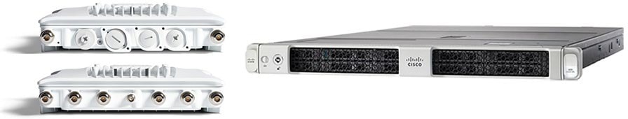 |
Table 10. Scalability
| Feature |
IW9167E |
Scale |
| Scalability |
Up to 5 Gbps |
Up to 40 Gbps |
| Core |
2048 MB DRAM |
3rd Gen Intel Xeon |
| Ports: RJ45 |
1X 100M/1000M/2.5G/5G |
Dual 10GBASE-T X550 ethernet |
| Ports: fiber |
1 x SFP(Copper) 100M/1000M/10G or 1x SFP (fiber) 1G/10G |
UCS VIC 1455 Quad Port 10/25G SFP28 CNA PCIE |
| Power supply |
Single (AC/DC), PoE+, PoE++, UPOE, power injector |
UCS 1050W AC power |
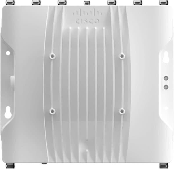 |
The IW9167E is deployed to create point-to-point, point-to-multipoint, mesh, and mobility networks for outdoor and industrial environments. It is designed with external antenna ports to provide flexibility in choosing the right antenna based on the use case.
It is especially suitable for wayside-to-vehicle communication in industries where reliable, stable, and low-latency communications are essential for safe operations and optimal productivity. The IW9167 has all the benefits of Wi-Fi 6 including higher density, throughput, channels, power efficiency and improved security.
For the offshore windfarm deployment, IW9167E can be used as an infrastructure radio on the OSS, turbines, and vessels. IW9167 models support Wi-Fi 6 and 6-GHz which can boost capacity and help mitigate interference with its tri radio design. The IW9167 can also be used on board the SOV as a Mesh Point operating in vehicle mode which is intended for vessels with roaming intent. It is important to note that the IW91671 does not support URWB mode at the time of this writing.
● IW-ANT-H90-510-N Antenna
The Cisco Symmetrical Horn is a connectorized symmetrical horn antenna with carrier class performance. It offers unique RF performance in a compact package. Scalar horn antennas have symmetrical beams with identical patterns in the vertical and horizontal planes. Extremely small side lobes result in decreased interference. Horn antennas are ideal for covering areas with close-in clients where null zone issues occur. This antenna makes high density AP clusters and radio colocation practical due to its radiation pattern and compact size. The IW-ANT-H90-510-N antenna is equipped with N-female connectors.
 |
BATS FAST 5.8 Intelligent Antenna System
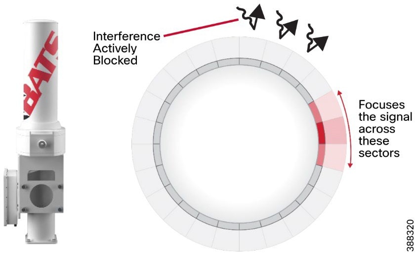 |
BATS Wireless is a Cisco design-in partner. When integrated with Cisco industrial wireless products, including the URWB backhaul and cellular gateway solutions, the BATS systems, deliver ultra high-capacity connectivity for mobile and vehicles and SOVs. Ideal for the unique demands of onshore and offshore operators in the energy, shipping, public transport, and defense markets, the integrated solutions provide the flexibility that is needed for dynamic and adaptive networks. They deliver a wealth of cutting-edge wireless communications and data opportunities for IoT sensing and monitoring applications, autonomous and augmented control applications, and intelligent multi-network roaming solutions.
The BATS FAST 5.8 high performance antenna is an ultra-fast (sub-500 ns) antenna array with 24 micro sectors. The solid-state and compact FAST antenna proves ideal for highly mobile environments where only minimal space is available, such as on a vehicle or small vessel.
A typical omnidirectional antenna is a passive antenna that radiates the signal in all directions equally. The BATS wireless FAST antenna is an active antenna made up of a cylindrical antenna array that sends a signal to a specific point, when required. Unlike a traditional omni or sector antenna, the FAST deploys active interference mitigation to block out unwanted signals while transmitting.
For the offshore windfarm deployment, we recommend that the BATS FAST 5.8 antenna be installed on the SOVs. For more information, see the BATS website.
Note: It is not mandatory to use the BATS Antenna on SOVs. The OMNI-5-KIT antennas can be used for the URWB radios on-board an SOV and the appropriate LTE antennas can be used for Cisco IR-1101 routers.
Industrial Wireless (IW) Service is a centralized cloud-hosted server that can be used for provisioning of an entire URWB system, including configuration, firmware upgrade, and plug-in activation. It allows all the radio configuration to be done in a single pane and uploaded to radios in real time or offline. IW Service supports almost all URWB configuration options (basic and advanced). IW Service can be used to create configuration templates and apply them to multiple URWB devices of the same type. Templates can be applied in either online mode (if the URWB devices have internet access) or offline mode (if the URWB devices have no internet access). We recommend IW Service for configuring URWB devices in deployments of any size.
URWB device provisioning can be done via two methods:
Online Configuration method:
● Automated template provisioning using the IW Service to push pre-built configuration templates to IP reachable URWB devices.
Offline Configuration method:
● IW Service-generated configuration files, to upload locally to URWB devices.
● Local manual configuration via the local URWB device gui.
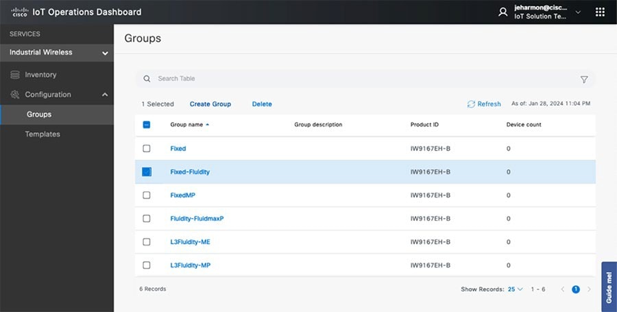 |
Note: See the “IOTOD” section within the Implementation Guide for step-by-step instructions on how to use IOTOD to create the appropriate URWB radio configuration templates and configuring URWB radio devices.
Online Configuration method:
When using Operations Dashboard prebuilt configuration templates can be pushed down to reachable URWB devices. These templates can be applied to device groups which is designed to simplify the deployment with like devices. Once the device comes online and is reachable from OD, the prebuilt template can be pushed down to the device from Inventory. Operations dashboard maintains feature parity with the offline configuration mode using the webUI. In the scenario where a device is offline then the specific configuration can be downloaded from OD Inventory and loaded manually via the local webUI of the URWB. Operations Dashboard provides the ability to inventory radios and enhance the ability to deploy updates and changes more efficiently from one single pane of glass.
Offline Configuration Method:
URWB can be configured in the offline mode if the unit does not have internet connectivity. This requires that the unit be set to IOT-OD offline mode within the CLI to be configured locally. From there, configurations can be made from the local webUI manually or by adding the downloaded configuration file (.conf). The URWB radio’s management IP can be used to access the webUI. Any changes must be saved in the webUI or the CLI and rebooted to take effect.
IW Monitor: Centralized Management of URWB Infrastructure
IW Monitor is a network-wide, on-premises monitoring dashboard that allows any URWB customer to proactively maintain and monitor one or more wireless OT networks. IW-Monitor displays data and situational alerts from every URWB device in a network in real time.
IW Monitor supports fixed and roaming network architectures and allows easy end-to-end troubleshooting. It can be operated as a standalone system or in parallel with a sitewide simple network management protocol (SNMP) monitoring tool. It is designed to support network installations used in wind farms, smart cities, rail, mining, renewables, ports and terminals, entertainment, smart factories, and military applications.
Note: This document does not provide setup or configuration instructions for IW Monitor. For this information, see Cisco Ultra-Reliable Wireless Backhaul FM Monitor Configuration Manual.
IW Monitor provides the following features and benefits:
● On-premises monitoring for URWB networks
● Wizard setup for quick and easy installation and deployment
● Real-time dashboard displaying uptime, throughput, latency, jitter, and other network KPIs
● Customizable section view to easily check groups of radios
● Customizable monitoring alerts for prompt response
● Radio-by-radio data logging with a minimum sampling interval of 300 ms
● Real-time radio configuration display for quick and accurate troubleshooting
● Side-by-side comparison of radio KPIs over time and over vehicle position
● Data logging export to a syslog server
One of the biggest advantages of IW Monitor is the ability to configure alerts for a group of radios based on certain KPIs. Imagine needing to support an application mix of automation and CCTV. The set of radios supporting the automation application can be grouped and alarms configured for KPIs such as latency, jitter, RSSI, and so on. And the group of radios that support the CCTV network can have alarms configured using different KPIs such as Link Error Rate (LER), MCS rate, and so on.
The IW Monitor dashboard shows overall network performance and allows customizable segmentation of the network into clusters. This segmentation provides easy monitoring of network sections or parts of a fleet of vehicles, maximizing network usage and performance. Clusters can include backhaul point-to-point links, point-to-multipoint distribution networks, vehicle access networks, wayside networks, and vehicle-mounted radios. IW Monitor displays and tracks real-time KPIs within each cluster, including the number of active radios, number of connected IP edge devices, end-to-end latency, jitter, upload and download throughput in real time, and system uptime. At the time of this writing, IW Monitor only supports IW916x devices.
 |
The IW Monitor table view allows you to condense sections of the network into a tabular view, isolating specific radio configurations and performance statistics. During troubleshooting, this approach significantly reduces the time needed to understand system performance on a radio-by-radio basis.
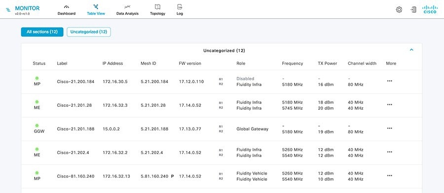 |
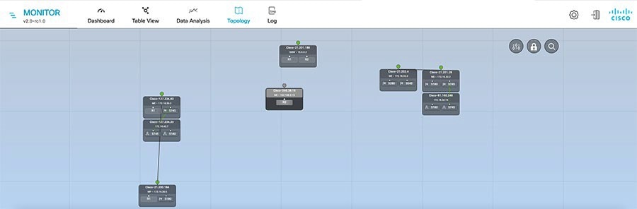 |
URWB: Terminology and Miscellaneous Configurations
This section covers concepts needed to understand the URWB architecture and deployment.
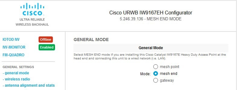 |
The mesh ID is a hardware identifier for URWB gateways and radios. It is preprogrammed at the factory with a hard-coded value that cannot be modified. The mesh ID is in the format of 5.x.x.x.
Note that a mesh ID is not an IP address. The mesh ID is relevant within the constructs of network design. A gateway or radio with a lower mesh ID becomes the “primary.” In addition, the gateway or radio with the lowest mesh ID becomes the mesh end (if a mesh end is not explicitly configured).
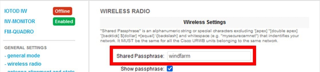 |
URWB gateways and radios are configured with shared passphrases. URWB control plane traffic is encrypted using this passphrase. The passphrase can also be used to segment a particular network so that radios with the same shared passphrase form a cluster and are kept separate from other mesh networks which use a different passphrase.
Note: Data plane and user traffic is not encrypted using the passphrase. To encrypt data-plan and user traffic, AES encryption must be enabled on gateways and radios.
If a shared passphrase is defined, the same passphrase must be used for all URWB units in the same network. As a deployment best practice, configure the passphrase to be something other than the default value of “URWB.” The shared passphrase can be composed of any ASCII characters except the following: ' ` " \ $ =
● Similar considerations as for normal MPLS
● MTU at endpoint 1500
● The minimum required MTU on switches is 1544
● Radios don’t have to be configured manually with MTU, this configuration is done automatically
Spanning tree protocol (STP) is a layer 2 protocol that runs on switches to prevent loops in the network when there are redundant paths in the network. Switches run the STP algorithm when they are first connected to a network or whenever there is a topology change. URWB radios do not participate in the STP alongside the switches. The radios simply forward or block BPDU messages, depending on how the radios are configured. URWB radios have an equivalent process to STP, called AutoTap, which helps avoid any loops within the wireless network.
BPDU snooping can be enabled or disabled on a radio. According to the configuration the radio acts or does not act on the contents of the BPDU.
BPDU forwarding, when configured as Pass, forwards all the BPDUs. BPDU forwarding, when configured as Auto, forwards the BPDUs within the wayside space and does not forward BPDUs to the vehicle space. Similarly in Auto mode, BPDUs are not forwarded from the vehicle space to the wayside space. When BPDU forwarding is configured as Stop, no BPDUs are forwarded.
AutoTap is a network loop prevention mechanism that allows URWB radios to detect connections and allow only a dedicated ingress or egress route to and from the mesh end or network core.
When AutoTap is enabled, only one radio in the physically connected redundant radio group advertises MAC address information. This radio is known as the primary radio, and is the radio with the lowest mesh ID. In this way, radios can detect each other over a wired connection and forward traffic to other connected radios utilizing the wired connection. Routes to the core and end devices are built automatically. The result is like having a single radio with multiple wireless interfaces.
As a best practice, network time protocol (NTP) should be configured on URWB radios. A primary and secondary NTP server IP address can be configured. When NTP is enabled on a radio, the radio synchronizes its time with the NTP server, usually within an hour. However, you can force this synchronization to happen sooner. The radio’s network connectivity goes down for milliseconds when you force it to connect to the NTP server.
Table 11 lists the VLANs and their purposes in a typical URWB deployment.
Table 11. VLAN Segmentation
| VLAN |
Purpose |
| VLAN-X |
URWB management VLAN. Used to connect, configure, and manage the URWB devices. Also used for control plane communication between the radio units. Every URWB device needs to have an IP address in this subnet for management reachability. |
| VLAN-Y |
Client traffic VLAN. Each client device, for example on board cameras, sensors, VCUs, and so on, have an IP address within this subnet. Multiple client VLANs can be used based on segmentation requirements. |
| VLAN-Z |
URWB native VLAN. This VLAN should not be used on the wired network. For example, a dummy value such as ‘999’ can be used. Note that when the URWB native VLAN is configured with a value of ‘0’ all untagged traffic will be dropped. |
| VLAN-A |
Switch management VLAN. Each LAN switch should have an IP address from this subnet for management reachability. Used to connect, configure, and manage the switches within the deployment. |
On URWB radios, VLAN support is not enabled by default and can be enabled by installing an optional plugin. We recommend that you Install and enable the VLAN plugin to control how tagged and untagged traffic is propagated through the network. When the plugin is enabled, two VLANs are configurable, one for management of radio units and one for the URWB native VLAN. The URWB management VLAN is used for control plane communication between the radios and to connect, configure, and manage URWB devices. The native VLAN determines how untagged traffic is handled as it passes through a radio. Setting the native VLAN to 0 is a special case that causes all untagged traffic to be dropped and allows only tagged traffic to pass through the radio.
The switch interface connected to a URWB radio should be configured as a trunk port carrying the URWB management VLAN and the client traffic VLAN or VLANs. Note that the URWB radio does not have the capability to tag VLANs, so VLAN tagging should be done on the directly connected switch.
A logical mesh end can be redundant and consist of two physical mesh end gateways or radios by utilizing the MPLS fast failover feature. The mesh end typically is configured within the core network. The purpose of an ME radio is to terminate all MPLS label switched paths (LPSs) and to act as a gateway between the URWB network and the wired network. The mesh end stores all LSPs to all the other radios in its database. URWB Mesh Ends is also where smart licensing settings are configured and managed.
Note: Note: Even though the URWB solution has the capability to automatically select a gateway or radio with the lowest mesh ID to become the ME, as a best practice we recommend that you configure the role of ME and mesh points manually within the deployment to have more deterministic convergence in case of a failure within the network.
By default, a full mesh of LSPs is created. However, within an offshore wind farm deployment, a full mesh of LSPs from each radio to each of the other radios within the network is not needed. LSPs are needed only from each mesh point to the mesh ends. This configuration is made with the Pseudo wires set parameter within OD. Change this parameter from the default setting of All to Mesh-Ends only.
URWB Mobility Architecture: Layer 2 Fluidity
Figure 34 depicts a typical URWB layer 2 fluidity mobility architecture for offshore wind farm SOV to OSS connectivity. A prerequisite for layer 2 fluidity is that all the URWB devices (mesh end gateways, access radios and mobile radios) must be within the same VLAN, IP subnet, and layer 2 broadcast domain and configured with the same passphrase.
The OSS infrastructure network consists of a redundant pair of mesh end gateways. The role of the mesh ends is to terminate the MPLS tunnels from each of the SOV radios and act as demarcation points between the wired and the wireless domains. The mesh ends are responsible for de-encapsulating the MPLS header and then forwarding the traffic to the distribution or core switch. For the traffic originating from the wired network and going toward the mobility domain, mesh ends act as default gateways and are responsible for the MPLS encapsulation and forwarding traffic to the appropriate SOV radio.
Access radios are configured as mesh points in the layer 2 fluidity mode with same passphrase that is configured on the mesh ends. The role of the access radios is to provide RF coverage for the mobility domain. Access radios are distributed across the area where wireless coverage is required while the SOVs roam. For small to medium offshore wind farms, the four URWB radios on the OSS might provide sufficient RF coverage for the SOVs. For larger offshore wind farms, URWB radios might need to be deployed on some of the turbines to address any RF coverage gaps. In this design, all access radios are configured to operate on the same frequency, which is known as a single frequency design.
Radios on the SOVs are configured in Vehicle mode and are statically configured to use the same frequency used on infrastructure radios.
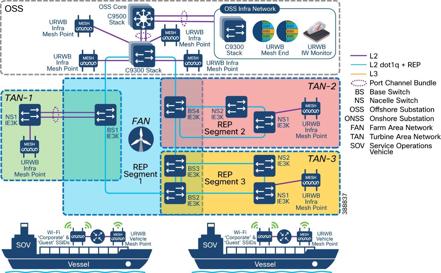 |
The network architecture is based on Prodigy 2.0, an MPLS-based technology, which is used to deliver IP-encapsulated data. MPLS provides an end-to-end packet delivery service that operates between levels 2 and 3 of the OSI network stack. It relies on label identifiers, rather than on the network destination address as with traditional IP routing, to determine the sequence of nodes to be traversed to reach the end of the path. An MPLS-enabled device is also called a label switched router (LSR). A sequence of LSR nodes configured to deliver packets from the ingress to the egress using label switching is called a label switched path (LSP), or tunnel. LSRs that are situated on the border of an MPLS-enabled network and other traditional IP-based devices are called label edge routers (LER).
The ingress node of the path classifies incoming packet according to a set of forwarding equivalence classes (FEC). When a packet matches a class, the packet is marked with the label that is associated with a particular class and then forwarded to the next node of the sequence, according to information that is configured in the forwarding information table (FIB) of the node. Subsequently, each intermediate node manipulates the MPLS labels that are stored in the packet and then forwards the data to the next node. The egress node finally removes the label and handles the packet using normal IP routing functions.
The FIBs on the different nodes of a network are managed by the label distribution protocol (LDP). which is the primary component of the network control plane. Fluidity relies on a custom LDP that provides automated installation of LSPs in the different nodes of the network. This approach ensures that each node can be reached from any other node.
In traditional MPLS networks, whenever the network topology changes, the FIBs of the nodes that are involved must be reconfigured to adapt to the new paths. This reconfiguration usually is performed using the standard LDP signaling that is available.
In a mobility network, the handoff process can be assimilated into a network topology change, where a link is broken and a new one created, as with Wi-Fi. However, the standard mechanisms to detect a change and reconfigure the nodes are too slow and data-intensive to provide adequate performance in a real-time constrained scenario, such as high-speed mobility. In particular, the reconfiguration latency and the number of messages exchanged should be minimized to reduce the chances that some data packets are lost in the process.
To mitigate these issues, fluidity implements a fast handoff solution that can provide very fast path reconfiguration with latency in the order of one millisecond. The fast handoff mechanism is an extension to the existing control plane of the network and is based on a specific manipulation technique concerning the MPLS FIB tables of the nodes.
The scheme proposed allows mobile nodes, and client devices that are attached to them to maintain their IP addresses throughout the mobility process. All nodes are part of a single layer 2 mesh network. The layer 3 handoff process is seamless in the sense that, because of a make-before-break strategy, the availability of at least one valid LSP is ensured during the transitory handoff as the network is reconfigured.
LSPs connecting to the static backbone are installed and updated whenever a vehicle performs the handoff procedure using dedicated signaling. LSPs are always present if a mobile radio communicates with a fixed infrastructure radio, although labels change as a vehicle roams.
Within standard Wi-Fi based communication, a handoff is triggered by the Wi-Fi client based on preconfigured static thresholds such as RSSI and SNR. For example, a Wi-Fi client might be configured to trigger a handoff when its RSSI value drops below –75 dBm. URWB, on the other hand, uses a dynamic handoff decision algorithm.
As shown in Figure 38, a vehicle radio always operates on the top line (RSSI envelope), handing over from the currently connected radio to the next available radio as soon as the difference in RSSI meets the configured hysteresis threshold. Figure 39 shows the fluidity predictive rate selection and the location where the fluidity handoff occurs.
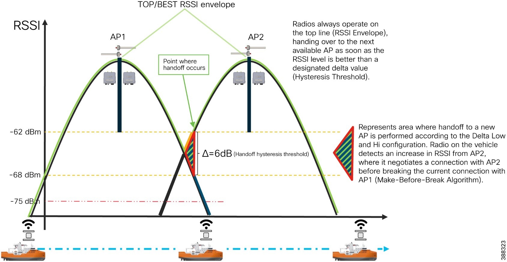 |
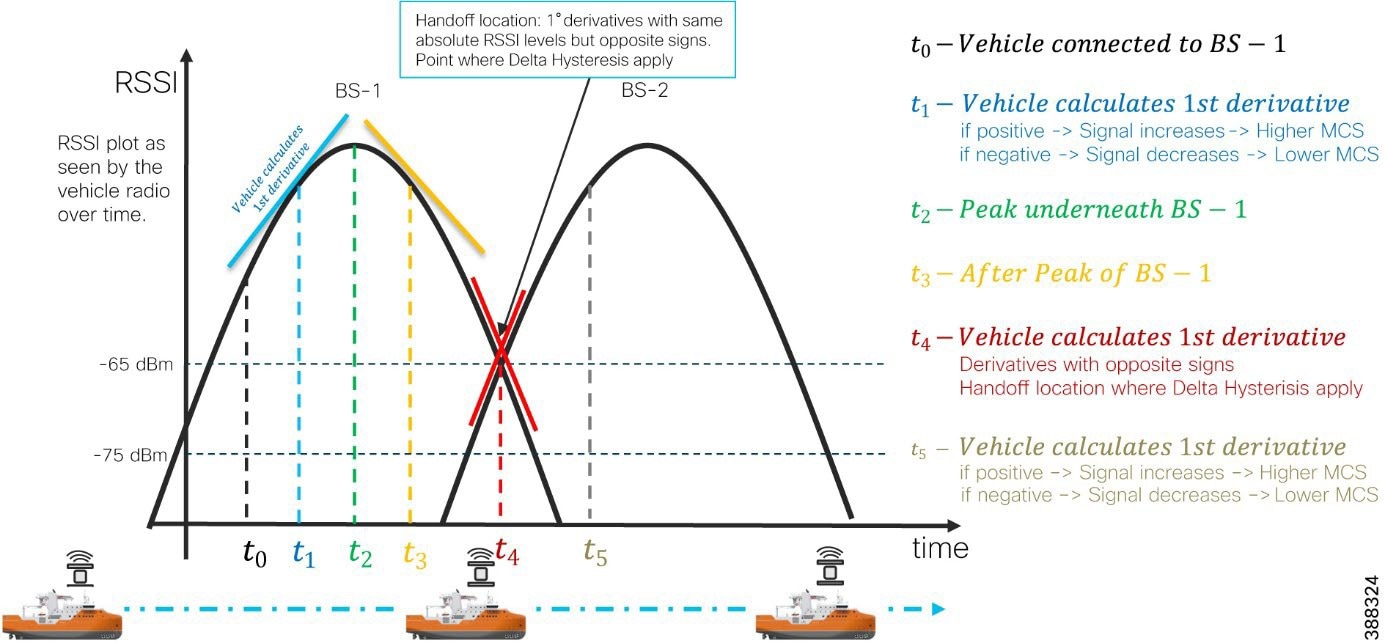 |
Fluidity Advanced Handoff Tuning for SOV Radios
The URWB solution provides certain advanced handoff parameters for vehicle radios that can be tuned depending on the RF environment to achieve optimal handoffs.
The RSSI zone threshold and handoff hysteresis threshold features provide safeguards against unwanted handoffs, that is, against unreasonably long periods between the received signal strength from a connected radio falling too low and a handoff request from a relief unit.
The relationship between the three settings that are shown in Figure 37governs whether a handoff takes place from one unit to another, based on a difference in comparative signal amplitude values over a period.
The RSSI low/high zone threshold sets the border between the low and high RSSI zones. In this case, as represented by the two graphs that are shown in Figure 38 and Figure 39, the –60 dB level marks the border between the low and high RSSI zones.
The threshold value is always expressed as SNR, with –95 dBm as the reference value, and is always expressed as a value greater than 0. The default value is 35. This value equates to –60 dBm.
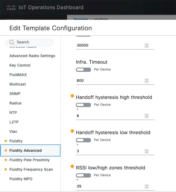 |
As shown in Figure 38, the default fluidity delta-threshold is –60 dBm. The default delta-high threshold is 6 dBm. With these settings, in good RF environments where the signal strength is higher than –60 dBm, the vehicle radio attempts a handoff to another wayside infrastructure radio only if the wayside radio provides a signal that is at least 6 dBm higher than what the vehicle is receiving from its currently connected wayside infrastructure radio. If the delta value is lower than 6, no handoff occurs at that time.
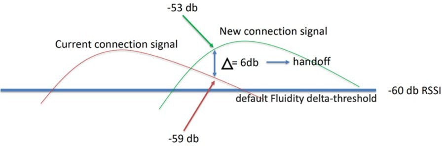 |
As shown in Figure 39, the default delta-low threshold is 3 dBm. With this setting, in poor RF environments where the signal strength is lower than –60 dBm, the vehicle radio attempts a handoff to another wayside infrastructure radio if the wayside radio provides a signal that is at least 3 dBm higher than what it is receiving from its currently connected wayside infrastructure radio. If the delta value is lower than 3, no handoff occurs at that time.
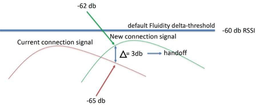 |
Note: The Fluidity delta-threshold, the delta-high value, and the delta-low value are all configurable by using either IOT OD or the radio CLI, if needed for your RF environment tuning.
URWB Fluidity Advanced: Large Network Optimization
Large network optimization (LNO) is useful in large network environments of more than 50 infrastructure radios. LNO helps optimize the MPLS forwarding table by establishing LSPs only toward the mesh end units.
The mesh end is the ingress or egress point of the MPLS domain. Spanning tree protocol (STP) also is affected because BPDU forwarding is disabled.
If LNO is enabled, the mesh points establish LSPs only with other mesh end devices. Enabling LNO also disables STP packet and BPDU forwarding.
If LNO is disabled, LSPs are created between all mesh points, and between mesh points and mesh ends. STP packets and BPDU forwarding are set to Automatic.
For an offshore wind farm deployment, we recommended that the LNO feature be disabled.
Note: If enabled, the LNO feature overrides the pseudo-wires configuration within MPLS settings.
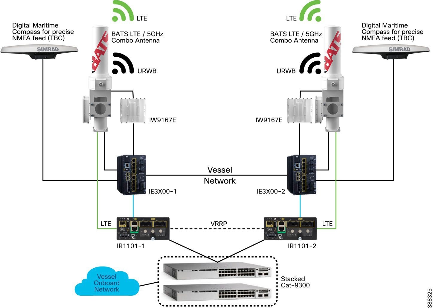 |
Figure 40 shows the SOV onboard network. The onboard Wi-Fi network (WLC and APs), wired ports, servers, and IP phones are connected to a stacked pair of Cisco Catalyst 9300 switches. The Cisco Catalyst 9300 stack is then connected to a pair of Cisco IR1101 routers with 5G and 4G-LTE SIMs that provide cellular connectivity when an SOV is close to shore and within range of a cellular tower.
When the SOV is farther out in the ocean, it uses satellite connectivity, which is out of scope of this CVD.
When an SOV is in range of the URWB network on the OSSs and turbines, the SOV switches to using dual URWB radios that are connected to BATS antennas to communicate with the OSS network, which has connectivity back to the control room and internet.
A BATS antenna that is deployed on an SOV serves two purposes. One port of the antenna is connected to a Cisco IR1101 router to provide 5G and 4G-LTE connectivity via a cellular network. The second port is connected to a URWB IW9167 radio to provide connectivity to the OSS URWB network.
VRRP is configured between two Cisco IR1101 routers to provide layer 3 redundancy.
The two URWB radios on an SOV are configured with the same passphrase and configured to operate in the Vehicle mode. Assign the unit a vehicle identity by using either of the following methods. For more information about performing this configuration, see the Implementation Guide.
● Allow the unit to automatically generate a unique vehicle identity by checking the Enable check box to the right of the Automatic Vehicle ID: heading.
● Assign a vehicle identity manually by unchecking the Enable check box to the right of the Automatic Vehicle ID: heading, and manually enter an identification string in the Vehicle ID: field.
Note: If vehicle identities have been manually assigned, the Vehicle ID string must be unique for each URWB unit that operates on the same network, even if more than one URWB unit is installed on the same vehicle.
The URWB network type must be configured as Flat’ because it uses the layer 2 fluidity deployment model. The SOV URWB radios must have a management IP address in the same subnet as the URWB infrastructure APs on the OSS and TAN.
The Handoff Logic setting controls the unit's choice of the infrastructure point with which to connect. For the SOV radios, configure this setting to the Standard handoff, which means the SOV URWB radio unit connects to the infrastructure URWB radio that provides the strongest signal.
The Rate Adaptation setting controls the unit’s choice of modulation coding and speed of packet transmission. For the SOV URWB radios, configure this setting to Advanced Rate Adaptation, which uses the URWB proprietary predictive rate selection algorithm.
The SOV network should be in a layer 2 ring to maximize traffic efficiency and minimize outages.
● URWB management VLAN should be present on all nodes.
● The Cisco IE3X00 should be designated as the STP root to minimize traffic hair pinning.
● Layer 3 SVIs should be configured on the Cisco IR1101 for the client gateway.
● VRRP should be configured on the Cisco IR1101s to load-balance different client subnets.
● Dynamic routing protocol should be used between SOVs and OSS to automatically choose the WAN interface.
● BATS specific (applicable only if using BATS antennas on the SOV): Configure the BATS antennas for GPS only tracking mode (dummy radio).
● RSSI mode requires constant telemetry from the attached radio. URWB radios send only telemetry when they are in the in primary role. In the secondary role, the radios send no telemetry. Therefore, the RSSI mode cannot be used effectively.
This section covers the high availability design for the URWB deployment.
Enable gratuitous APR (GARP) when enabling Fast Failover to advertise the secondary radios MAC address if the primary radio fails.
This section describes the URWB IW9167E Mesh-End redundancy and high-availability design.
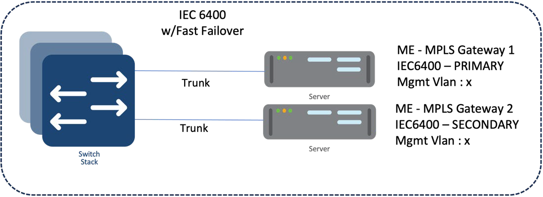 |
IW9167E/IEC6400 Mesh End Redundancy and High Availability
We recommend that you deploy a pair of mesh ends in the wind farm deployment for redundancy. Both the primary and backup should have the same configuration (frequency, channel width, role, cluster ID, etc.).
After fast failover is configured, it is completely autonomous and ensures stable and reliable connectivity without the need for any human intervention. If data exchange ceases because of the failure of the primary mesh end device, fast detects the failure and reroutes traffic through the designated secondary device, reestablishing connectivity within a maximum of 500 ms. When the failed primary mesh end device comes back online, the secondary mesh end device automatically reverts to its standby role.
We recommend that you connect the IW gateways to separate power sources and to different switches within the 9500 StackWise pair. This arrangement provides protection against power outages and switch hardware failure.
All URWB units that are connected to the same wired broadcast domain and configured with the same passphrase perform a distributed primary election process every few seconds. The primary unit is an edge point of the URWB MPLS network, that is, a device where user traffic may enter or leave the mesh. Secondary units act as MPLS relay points.
For each neighbor, the algorithm computes a precedence value based on the role of the unit (mesh end or mesh point) and its mesh ID. Mesh ends are assigned a higher priority than mesh points and, among the same priority, the unit with the lowest mesh ID is preferred. The election mechanism relies on a dedicated signaling protocol that constantly runs in the network and guarantees that all units elect the same primary unit.
During normal operation, the primary and secondary mesh ends constantly communicate to inform each other about their statuses and to exchange network reachability information. In particular, the primary mesh end periodically sends updates to the secondary mesh end regarding its internal forwarding table and multicast routes.
If the primary mesh end fails for any reason, the secondary mesh end times out after not receiving keepalive messages for a configurable interval, which typically is from 50 through 200 ms. At that point, the secondary mesh end becomes the new active mesh-end, taking over the role of primary mesh end, and it executes the following actions:
● Issues a primary change command to inform all other units on the same wired network that the primary has changed. The message also is propagated to mobile units by using an efficient distribution protocol.
● Updates the internal MAC and MPLS forwarding tables. This step is performed using a proprietary fast rerouting technique that provides seamless performance.
● Sends gratuitous ARPs for the onboard devices on its ethernet or fiber port. This action forces the network switch to update its MAC forwarding table (CAM table) so that it sends traffic for onboard destinations through the port that is connected to the new primary.
When the other units receive the primary change command from the secondary, they perform the internal seamless fast-rerouting procedure so that the traffic can immediately be forwarded with no additional delay or signaling required. This approach provides fast network reconvergence, with an effective end-to-end service disruption below 500 ms.
When the primary mesh end is recovered, it scans the network for the presence of an active secondary mesh end. If the detection is positive, the unit enters an inhibition mode wherein the secondary mesh end remains the current edge point of the infrastructure for a certain amount of time (70 seconds, by default). During this grace period, the primary unit receives updates from the currently active secondary mesh end and acquires full knowledge about the state of the network. Then, the secondary unit switches to being the primary unit, using the same procedure that is described above for failure.
URWB Access Layer: Fast Convergence on Failure
Link Backhaul Check: Handoff Inhibition
Using the link backhaul check feature, an access radio detects a carrier loss on its Ethernet or fiber port. With a carrier loss, an access radio unit loses its ability to deliver mobility traffic to the mesh end. The radio immediately advertises its status as Unavailable by transmitting a handoff inhibition message over the wireless channel. Upon receiving the handoff inhibition message, any existing mobile radio connected to the affected radio searches for another access radio. All mobile radios that are currently connected to affected access radio find and connect to an alternative access radio within a few hundred milliseconds, typically within less than 400 ms. In addition, handoff attempts from any other mobile radios to the affected access radio are rejected. We recommend that you enable the link backhaul check feature on access radios in a wind farm deployment.
Figure 42 shows a link between the access radio and its switch is down. Assuming that the radio is powered by an external power source, not by PoE, the radio is still up and providing good wireless connectivity to vehicles. However, because the wired link is down and the radio is not able to forward traffic to the wired network, the radio goes into handoff inhibition mode and rejects any handoff attempts from an SOV radio.
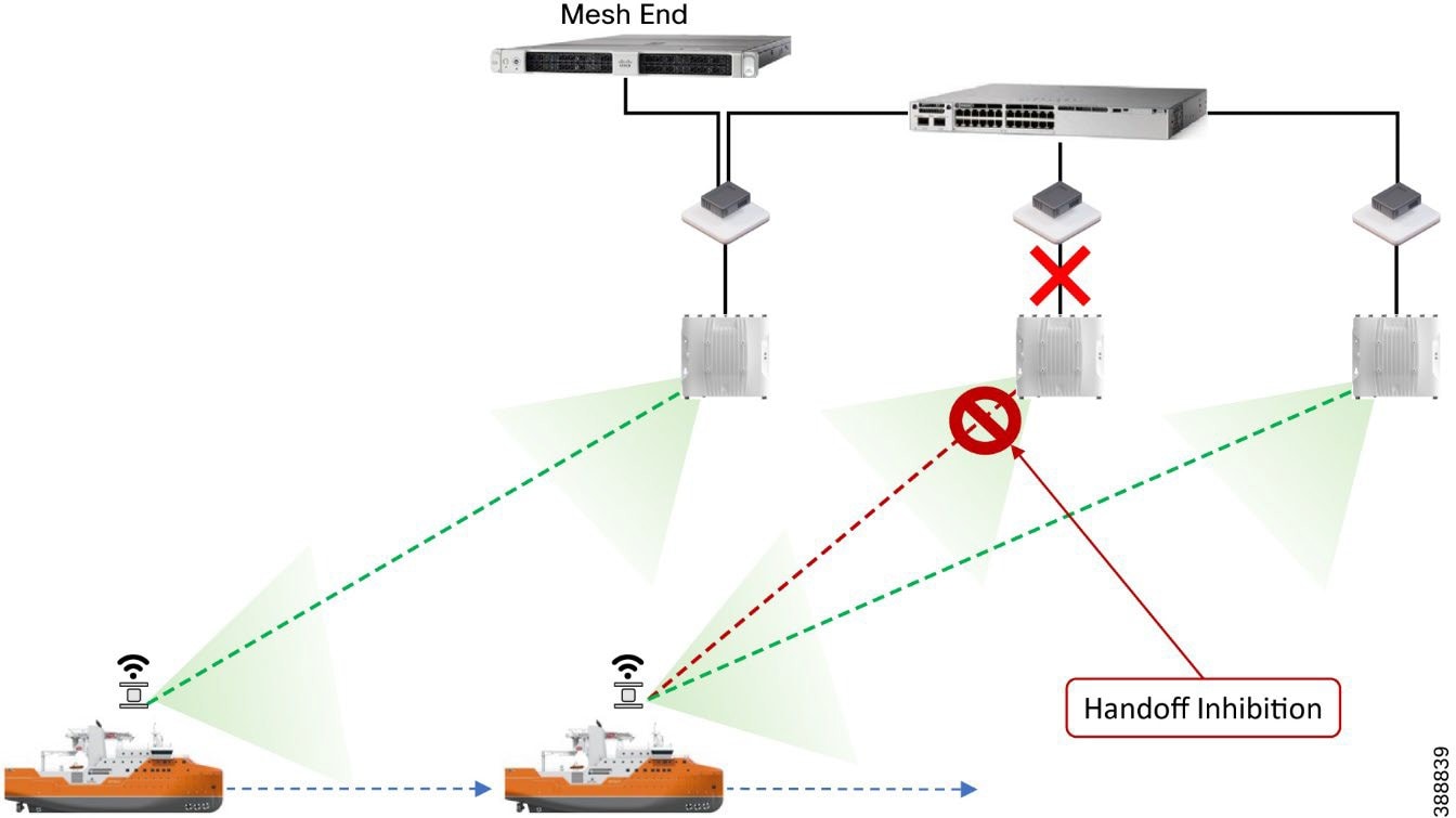 |
Mesh-End Backhaul Check: Handoff Inhibition
With the mesh end backhaul check feature, an access radio unit detects that it is not able to reach the active mesh end. This failure is triggered when layer 2 MAC reachability is lost to the active mesh end for 250 ms. The affected radio unit immediately advertises its status as Unavailable by transmitting a handoff inhibition message over the wireless channel. Upon receiving the handoff inhibition message, any existing mobile radios that are connected to the affected radio unit search for another access radio to connect to. All mobile radio units that are currently connected to the affected access radio find and connect to an alternative access radio unit within a few hundred ms, typically within less than 400 ms. In addition, handoff attempts from any other mobile radios to the affected access radio are rejected. We recommend that you enable the mesh end backhaul check feature on access radios in a wind farm deployment.
Figure 43 shows an access radio switch that has lost its fiber connectivity to the core switch. The access radio is powered on and providing good coverage and connectivity to vehicles. But because the radio is not able to forward traffic to the mesh end that is located within the control room, it goes into handoff inhibition mode and rejects the handoff request from the SOV radio.
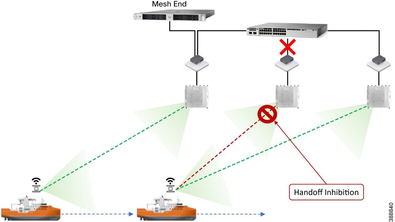 |
Onboard Radio Redundancy: Failover and Recovery
Fast failover high availability is not applicable for mesh ends only.
The onboard failover process is similar to the mesh end failover process. It encompasses the same steps described in the previous section by swapping the infrastructure and onboard networks.
The main difference in these processes is that when a mobile unit becomes the new primary after a failure or recovery event, the mobile radio executes the following additional actions:
● If the automatic vehicle ID feature is enabled, the mobile radio computes a new vehicle ID and forces the update on all onboard units.
● It performs a forced handoff procedure instead of sending a primary switch command to update the infrastructure network more efficiently.
All client traffic within an MPLS tunnel is already kept private by using the system passphrase. However, URWB radios also support AES encryption, which applies to MPLS tunnel traffic on wireless links.
When configuring AES encryption, AES encryption must be enabled on all radios within the system. Enabling AES only for a part of the system is not supported and causes a breakage.
SCADA Applications and Protocols
Turbine OEM and wind farm operators have steadily moved their substation operations to standard-based network (Ethernet, TCP/IP) with standard communication protocols, such as IEC 61850, DNP3 TCP, Modbus-TCP, IEC 60870-5-104, and OPC-UA. Nonetheless, a substation often contains devices that, for several reasons, are difficult or cost-prohibitive to migrate to standard-based network connectivity. These devices often use a variety of serial-based legacy SCADA protocols, including OPC-UA, Modbus, and IEC 60870-5-101. Because these devices often are critical to substation operations, they must be interconnected to the centralized SCADA applications of the substation operator.
SCADA protocols provide access to and from key operational devices within a wind farm network and a secure connection to the control center for telemetry and operational data. The OSS core provides key connectivity to these operational devices and communicates via these protocols over the WAN to the control center.
The types of devices that provide key operational data include:
● Wind turbine monitoring and control
● Fire detection and alarming
● HVAC
● Power systems protection and control
● Environmental and weather systems
● Wildlife detection and monitoring systems
● Lightning detection
● Marine systems (radar, radio)
These devices usually are key to operating a wind farm, providing both monitoring and control capabilities. Legacy SCADA protocols, which are supported over legacy asynchronous interfaces, include:
● Modbus
● DNP3
● IEC 60870-5-101 (also known as T101)
Newer SCADA IP-based protocols that can be transported over Ethernet interfaces include:
● OPC UA
● Modbus-IP
● IEC 60870-5-104 (also known as T104)
Many other SCADA protocols exist, but in the wind farm turbine SCADA network, only those listed above are commonly used.
Open Platform Communications Unified Architecture
Open Platform Communications Unified Architecture (OPC UA) is a data exchange standard for industrial communication (machine-to-machine or PC-to-machine communication). This open interface standard is independent of the manufacturer or supplier of an application, of the programming language in which the respective software was programmed, and of the operating system on which the application is running. OPC UA is the next generation of OPC technology. It's a more secure, open, reliable mechanism for transferring information between servers and clients.
In this architecture, there are two mechanisms for exchanging this data:
● A client-server model in which unified architecture (UA) clients use the dedicated services of the UA server
● A publisher-subscriber model in which a UA server makes configurable subsets of information available to any number of recipients
In a wind farm, communication between a turbine operator network and wind farm asset operator’s OSS infrastructure client is done using OPC UA protocol. OPC UA is a client-server based model in which an asset operator’s OPC UA client in the OSS infrastructure can read turbine monitor and operational data from an OPC UA server in the turbine operator network for turbine monitoring in an offshore substation, as shown in Figure 44.
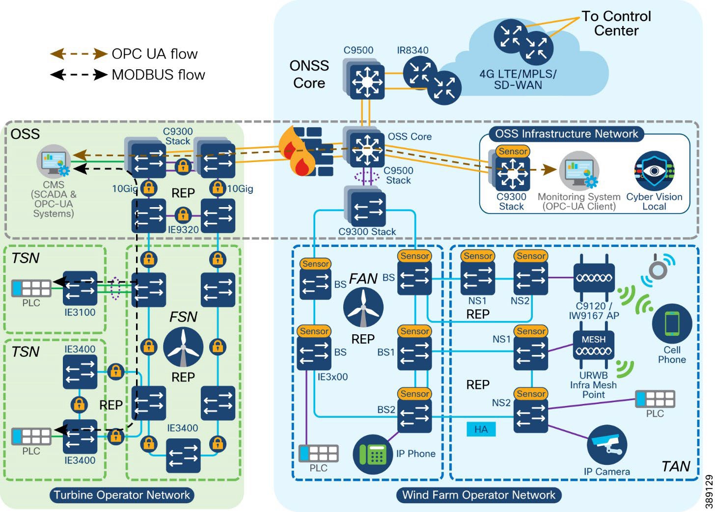 |
In Figure 44, a Programmable Logic Controller (PLC) or an Input-Output(I/O) device connected to a wind turbine SCADA switch communicates with a Conditional Monitoring SCADA System (CMS) connected to the turbine operator’s network core switch. This communication between CMS and PLC for collecting turbine’s operational data (for example, turbine rotation speed) uses SCADA MODBUS TCP protocol. A wind farm operator’s monitoring system in OSS infrastructure network could request a turbine’s operational data from CMS via firewall. This request uses a standard OPC UA protocol for communication with a CMS or an OPC UA server in the turbine operator network.
The following flow diagram depicts the OPC-UA and SCADA MODBUS TCP protocol messages between a PLC, CMS and a monitoring system in the turbine and wind farm operator networks. An example use case of reading turbine rotational speed using an OPC UA client (uses the standard OPC-UA protocol) in the wind farm operator network, is shown in the Figure 45.
The wind farm operator OSS infrastructure C9300 network access switch is installed with a Cybervision sensor which captures the OPC-UA packets flowing through the turbine and wind farm operator networks. Detailed implementation of OPC UA server and clients along with CV sensor to capture this flow is covered in the implementation guide of this CVD.
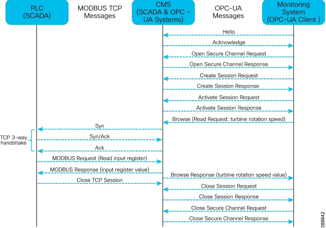 |
Modbus TCP/IP (sometimes referred to as the Modbus TCP protocol or just Modbus TCP) is a variant of the Modbus family of simple, vendor-neutral communication protocols intended for supervision and control of automation equipment. Modbus TCP covers the use of Modbus messaging in an intranet or internet environment using the TCP/IP protocols. The most common use of the protocols is for the Ethernet attachment of PLCs, HMIs, I/O modules, and sensors to other I/O networks.
IEC 60870-5-104 (also known as T104) enables communication between a control station and a substation via a standard TCP/IP network. The TCP protocol is used for connection-oriented secure data transmission.
● T101 and T104 refer to IEC 60870-5-101 and IEC 60870-5-104 Standard respectively.
● T101 supports point-to-point and multi drop links over serial communications.
● T104 utilizes TCP/IP transport and network protocols to carry application data (ASDU), which is specified in T101.
● T104 allows balanced and unbalanced communication types.
● Balanced mode is limited to point-to-point links in which either station can initiate a transaction (similar to a dnp3 unsolicited response).
● Unbalanced mode is suitable for multi-drop links in which only the primary station can send primary frames.
Quality of Service (QoS) refers to the ability of a network to provide preferential or differential services to selected network traffic. QoS is required to ensure efficient use of network resources while adhering to business objectives. QoS also refers to network control mechanisms that can provide various priorities to different endpoints or traffic flows or guarantee a certain level of performance of a traffic flow in accordance with requests from application programs. By providing dedicated bandwidth, controlled jitter and latency (required by some real-time and interactive traffic), and improved loss characteristics, QoS can ensure better service for selected network traffic.
The wind farm network architecture consists of different kinds of switches with different feature sets. A QoS model is important to guarantee network performance and operation by streamlining traffic flow, differentiating network services, and reducing packet loss, jitter, and latency.
QoS policies can be defined to classify ingress packets based on access control lists (ACLs), IP address, or class of service (CoS), set appropriate CoS values at ingress, and use the CoS values for further treatment on egress. We recommend classifying wind farm voice, video and network control packets on ingress based on ACLs or IP differentiated services code point (DSCP) values into the priority queue on egress. Remaining traffic can go into classes with guaranteed bandwidth.
Note: This section describes the QoS design consideration for the wind farm asset operator’s network. A separate QoS design section is added for turbine operator’s network QoS consideration which is discussed in section “TSN Quality-of-Service design”.
Table 12 lists the possible traffic types in a wind farm network and the corresponding recommended ingress and egress classification, bandwidth, and QoS treatment.
Table 12. Wind Farm Traffic Types, Bandwidth, and QoS Requirements
| Traffic Classes |
DSCP |
PHB |
COS |
Queue type |
Assigned BW |
Drop policy |
Protocols |
|
|
IP routing |
48 |
CS6 |
6 |
Priority |
100 Mbps |
WTD |
OSPF, EIGRP, BGP, HSRP, IKE |
|
| Latency sensitive critical data |
47 |
EF |
6 |
WTD |
– |
|||
| Voice |
46 |
EF |
5 |
Priority |
300 Mbps |
WTD |
RTP |
|
| Mission critical data |
40 |
CS5 |
7 |
WTD |
OPC UA |
|||
| Interactive video |
34 |
AF41 |
4 |
WTD |
CCTV |
|||
| Streaming video |
32 |
CS4 |
4 |
|||||
| Call signaling |
24 |
CS3 |
3 |
CBWFQ |
450 Mbps |
WTD |
SCCP, SIP, H323 |
|
| Locally defined mission critical |
26 |
AF31 |
-
WTD |
- |
||||
| 5 |
||||||||
| Transactional Data and URWB |
18 |
AF21 |
2 |
|||||
| Network management |
16 |
CS2 |
3 |
WTD |
SNMP, SSH, Syslog |
|||
|
Bulk data |
10 |
AF11 |
1 |
CBWFQ |
150 Mbps |
WTD |
Email, FTP, backup apps |
|
| Best effort |
0 |
CS0 |
0 |
Default class |
||||
| Scavenger |
8 |
CS1 |
0 |
Internet |
● Cisco IE3400 switches in the TAN and FAN support one priority queue, seven class-based queues, and two QoS thresholds (1P7Q2T) at each egress interface. Traffic mapping at egress queues in the IE switches is performed as the QoS design shown in Figure 46.
● Cisco Catalyst 9300 Series and 9500 Series Switches in OSS and ONSS networks support two priority queues, six class based queues, and three QoS thresholds (2P6Q3T) at each egress interface.
● Ingress traffic classification is based on DSCP, ACLs, or IP address (layer 3) and CoS or MAC ACL (layer 2), depending on the traffic type and set COS value.
● Each egress interface in the TAN, FAN, aggregation, and core switches in a network is mapped with a queuing policy.
● Egress weighted tail drop (WTD) is considered for the traffic beyond a certain bandwidth percentage.
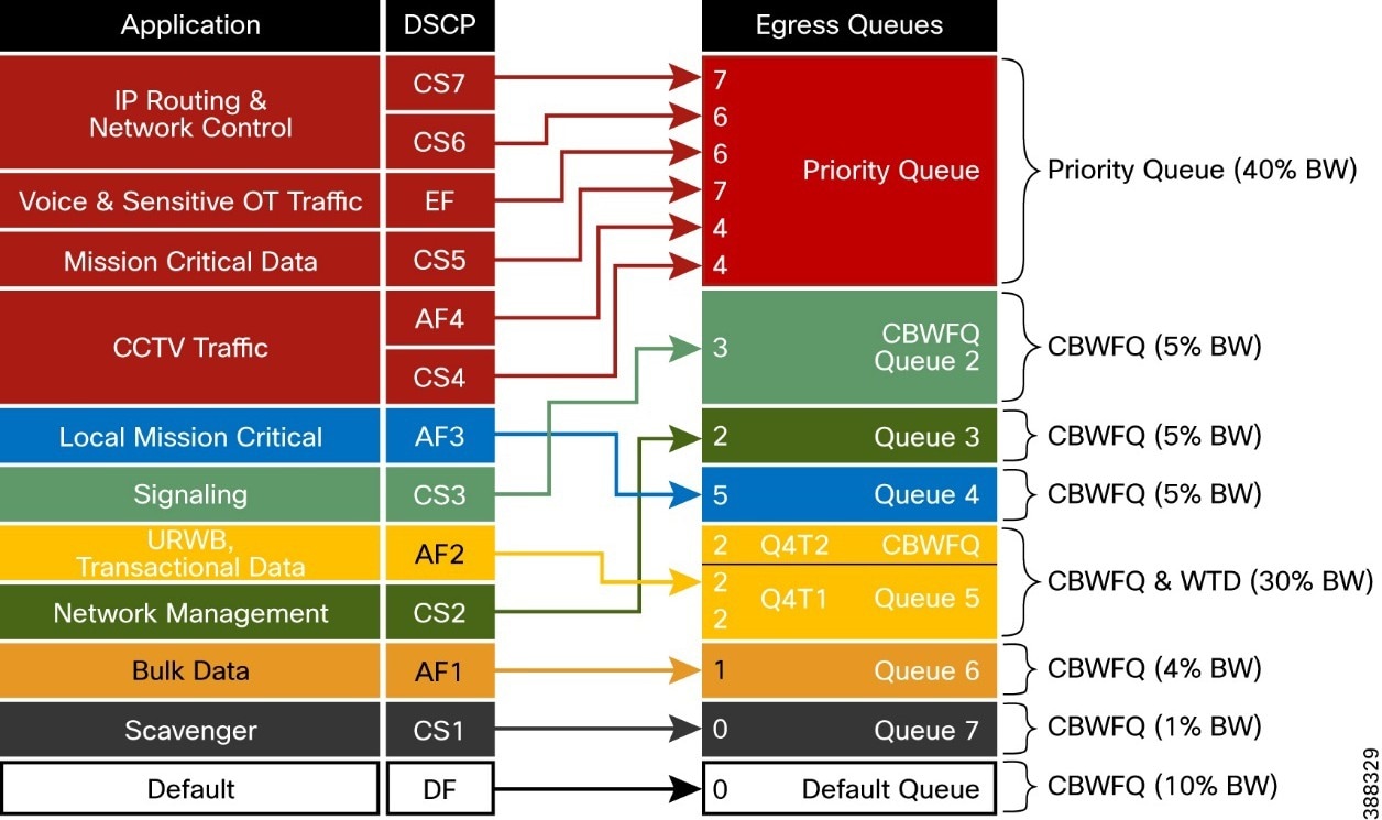 |
Cisco Industrial Ethernet switches support the modular QoS command line interface. The modular approach can be implemented using the following steps.
● Identify and classify the traffic. Various classification tools such as access control lists (ACLs), IP addresses, CoS, and IP differentiated services code point (DSCP) can be used. The choice of the tool depends on traffic types.
● Perform QoS functions on the identified traffic. Available QoS functions include queuing, policing marking, shaping, and more. Functional selection depends on ingress or egress application traffic flow requirements.
● Apply the appropriate policy map to the selected interfaces.
Turbine Operator Network Design
This section discusses the design of an offshore substation (OSS) turbine operator (also known as a third-party network) in a Wind Farm. This turbine operator network design is independent of Wind Farm operator network in offshore substation but interconnects with it via a firewall for the exchange of turbine telemetry data between these two networks.
OSS (third-party) Turbine Operator Core Network Ring Design
An offshore substation turbine operator core network design is composed of a pair of cabinets with each cabinet having a stack of two Catalyst 9300 Series switches that provide resilient core networking and routing capabilities. In this design, two cabinets with each cabinet having a stack of Cisco Catalyst 9300 switches are used along with a pair of Cisco Industrial Ethernet (IE) 9300 Rugged series switches in a ring topology to form a resilient 10 Gigabit Ethernet core network, as shown Figure 47.
Cisco IE-9300 rugged series switches in the core network ring aggregates Farm Area SCADA Network (FSN) rings (subtended rings of core REP ring).
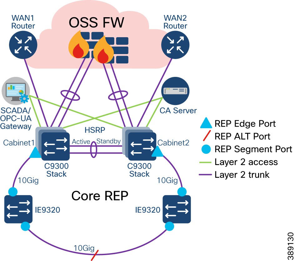 |
● Turbine operator core network is comprised of two cabinets which are geographically separated across different locations to provide high available core network; Each cabinet is having a stack of two Cisco Catalyst 9300 Series Switches
● Two core network cabinets along with two Cisco Industrial Ethernet 9300 Series Switches (Top-of-Rack) in a ring topology forms a 10GE Core network for turbine operator in OSS
● Two uplinks from a stack of Catalyst 9300 Series switches are connected to OSS Firewall in a port channel configuration to interconnect and exchange turbine telemetry data with wind farm asset operator network
● An open REP ring is configured on these C9300 stacks and IE9300 switches in the core ring to provide a resilient layer 2 network design for all VLANs in the core network. This REP segment also acts as a main REP segment for the subtended rings that are aggregated in the IE9320 switches
● IE9320-22S2C4X device model with 4 Qtys of 10GE (SFP+) fiber uplink and 24 Qtys of 1GE (SFP) fiber downlink ports is chosen in this core REP ring design to provide high bandwidth core network and aggregates 1GE Farm Area SCADA network (FSN) rings
● The Hot Standby Router Protocol (HSRP) is configured between these two stacks of Catalyst 9300 switches, to provide IP routing redundancy design that allows for transparent failover of first-hop gateway for all VLANs/Layer2 networks configured in the core ring
● Routing from the core switches to Cisco Secure Firewall or to any WAN edge router for remote branch /Control Center connectivity is done using a point-to-point layer 3 port-channel link. HSRP configuration with default gateway for each VLAN is done on logical layer 3 SVI on C9300 core switches
● OSPF or any other routing protocol can be configured for the routing from core switches to Cisco Secure Firewall or any WAN edge router for remote branch/Control Center connectivity
● The core Catalyst 9300 switches stack also offers Dynamic Host configuration Protocol (DHCP) services for the endpoints/devices in the FSN or TSN; the DHCP IP address pool is configured in core C9300 switches stack for local subnets/VLANs in turbine operator network to facilitate the dynamic IP address assigned for IP based endpoints/devices in FSN/TSN
OSS (third-party) Turbine Operator Aggregation Network Design
Two Cisco IE9300 rugged series switches in the core network ring aggregates rings of turbine base SCADA switches. Uplink ports of these two standalone IE9320 switches are connected to core REP segment and downlink ports are connected to Farm area SCADA network (FSN) rings, as shown in Figure 48.
● 2 Qtys of IE9320-22S2C4X switches in a standalone deployment aggregate up to 24 FSN REP rings based on downlink ports density in the two switches of IE9320-22S2C4X. However, it is recommended to aggregate up to 8 FSN REP rings for a pair of IE-9320 switches for optimal performance
● This design considers a maximum throughput per FSN ring is up to 500Mbps
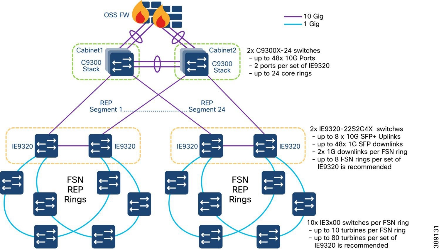 |
Farm Area SCADA Network (FSN) Design
In turbine operator network, the IE3400 and/or IE3100 Series switches as the base SCADA switch from each wind turbine is connected in a ring topology using a 1G fiber cable with Cisco Industrial Ethernet 9300 switches to form a farm area SCADA network (FSN) ring. A REP is configured in the FSN ring to provide FAN resiliency for faster network convergence if a REP segment fails.
Figure 49 shows a FSN ring aggregating to a pair of Cisco IE9320 switches in the core REP segment in turbine operator’s network aggregation layer.
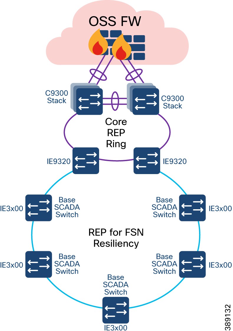 |
● Cisco Industrial Ethernet 3400 and/or 3100 series switches are used as turbine base SCADA network switches in the design
● A layer 2 open ring of turbine base SCADA switches connected via 1G fiber forms a Farm area SCADA Network (FSN) ring for turbine operators; FSN is a subtended ring of core REP ring
● FSN is a 1G open ring of up to 10 switches in a ring
● IE9320 switches in the core REP ring aggregates subtended REP ring traffic from each FSN
● When a ring of all IE3400 switches is used in FSN and TSN, REP is enabled on top of MACsec feature. For more details on MACsec in turbine operator network, refer to the section “MACsec Encryption in Turbine Operator Network”
● REP is configured for base SCADA switches/FSN resiliency such that REP edge ports are on IE9320s in core REP segment
● FSN base switches aggregate another subtended REP ring traffic from turbine nacelle SCADA switches with HA deployment
● Multiple VLANs are configured for network segmentation of FSN devices. Examples include VLAN for SCADA endpoints, management VLAN (FTP and SSH) etc.
Turbine SCADA Network (TSN) Design
In offshore wind farms, each wind turbine has a Cisco IE3400 switch deployed at the turbine nacelle for turbine operator network connectivity to various SCADA endpoints in the turbine operator network. These endpoints include SCADA devices, IEDs, I/O devices, and so on. The IE switch deployed in the turbine nacelle is also called a nacelle switch (NS). The NS with its SCADA endpoints forms a turbine SCADA network (TSN) in the wind farm OSS turbine operator network, as shown in Figure 50.
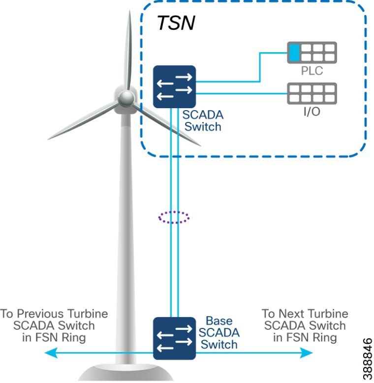 |
TSN Non-HA Design Considerations
● Single Cisco IE3400 switch deployed in each turbine nacelle, as shown in Figure 50 for the TSN non-HA design option turbine nacelle Ethernet switch.
● Layer 2 Star Topology (non-HA) of nacelle switches connecting to turbine base SCADA switch (shown in Figure 50).
● An LACP port-channel with two member links to a base SCADA switch provides link-level redundancy to TSN.
● Multiple VLANs for segmenting TSN devices are configured in the NS. Examples include separate VLANs for SCADA IED endpoints, PLCs, switchgears etc.,
● First hop security protocols with device authentication using MAB or Dot1x are configured for securing TSN endpoints.
● First hop (Layer 3) gateway for all VLANs with HSRP configuration in the OSS turbine operator core network C9300 switches
TSN High Availability Design with REP
An IE3400 nacelle switch in the TSN provides a single point of failure for TSN endpoints. To provide a highly available TSN, two nacelle switches are deployed for TSN endpoints network connectivity. In addition, a redundancy protocol REP is configured.
Two uplink ports from two nacelle switches deployed for HA in TSN, are connected to a turbine base switch.
There are two options for TSN high availability design. In the first option, shown in Figure 51, a closed ring topology of two nacelle SCADA switches connects to a single turbine base SCADA switch. This arrangement forms a subtended REP ring to the FSN ring in the turbine operator network.
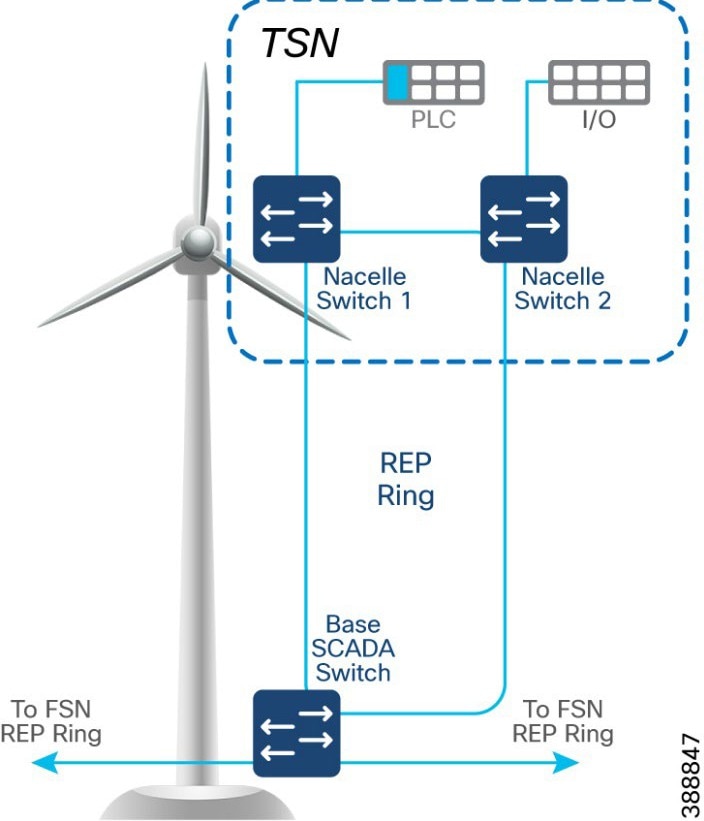 |
In the second option, shown in Figure 52, the uplinks from two nacelle switches are connected to two different base switches in a TSN, which provides redundancy for the turbine base SCADA switch network and the TSN. In this option:
● An open ring topology of two nacelle switches connects to two turbine base switches.
● A subtended REP ring of FSN REP ring of base SCADA switches is formed.
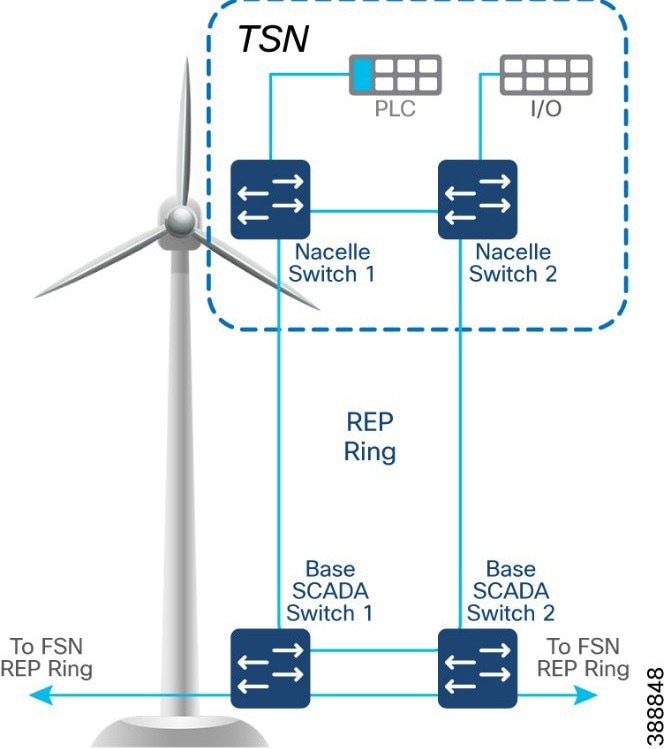 |
Multi-level advanced REP rings design across Cabinets
Turbine operator network with core REP rings and FSN REP rings across cabinets of different OSS locations along with TSN REP rings in turbine forms a multi-level REP ring (Ring of rings) from core network to the turbine nacelle SCADA network.
The Top-of-Rack (ToR) two IE9320 FSN aggregation switches connected to C9300 switches stack in two cabinets forms 2nd level open REP ring of ToR switches to provide location level network high availability for offshore substation ToR switches. Figure 53 illustrates the multi-level REP rings network design of turbine operator network.
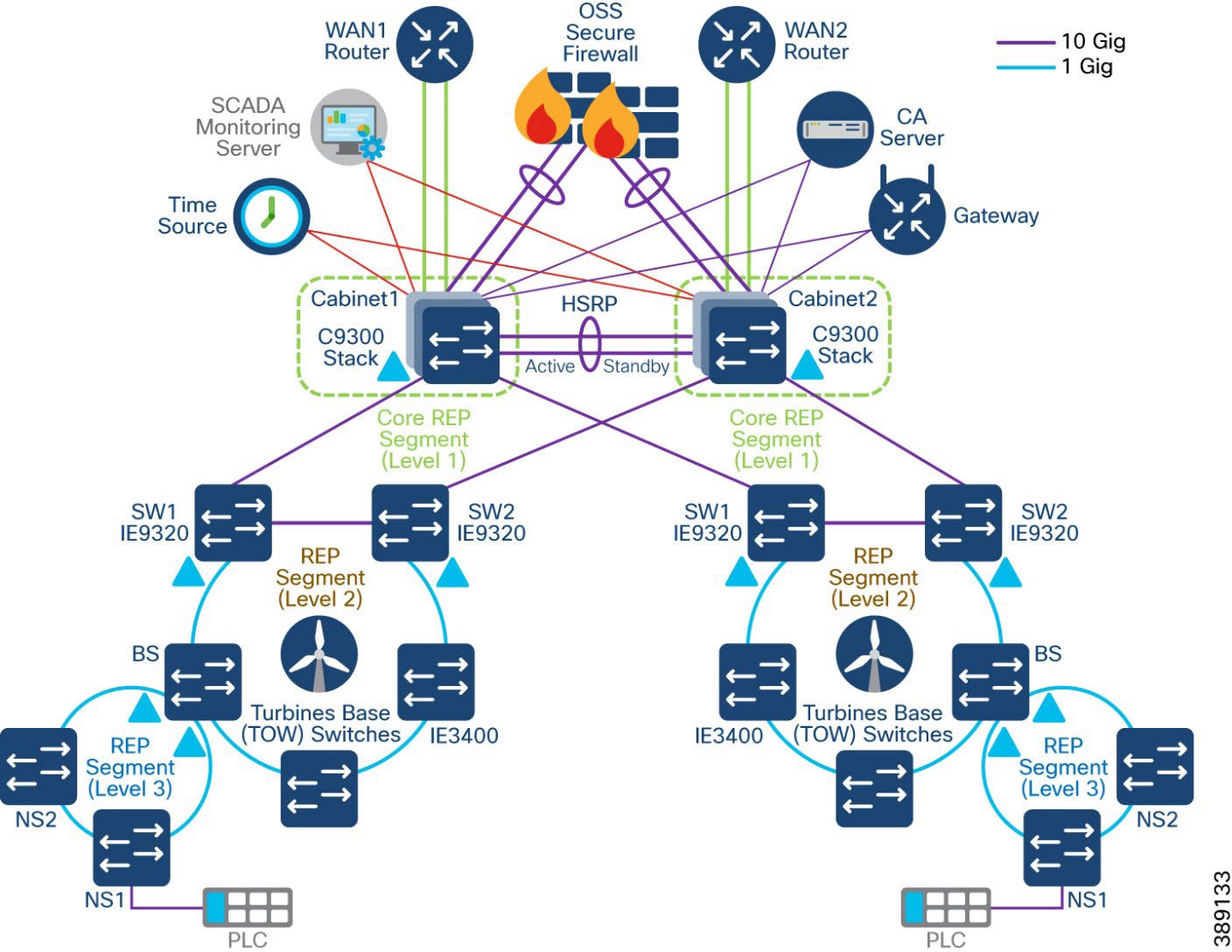 |
Media Redundancy Protocol (MRP) Ring design for FSN
Media Redundancy Protocol (MRP), defined in International Electrotechnical Commission (IEC) standard 62439-2, provides fast convergence in a ring network topology for industrial networks. MRP Media Redundancy Manager (MRM) defines its maximum recovery times for a ring in the following range: 10 ms, 30 ms, 200 ms and 500 ms. However, the default maximum recovery time on Cisco IE switch is 200ms for a ring composed of up to 20 nodes.
MRP modes are operating configurations that define how the switch interacts with the MRP network. These modes have distinct management interfaces and compatibility with external frameworks.
The switch supports two MRP modes, with only one mode being enabled at a time.
PROFINET MRP mode: Designed for integration with Siemens' Totally Integrated Automation (TIA) framework. This mode is primarily managed through the TIA framework and does not utilize the CLI or WebUI for MRP configuration. This mode is the default when the MRP is activated via the web interface or command line.
MRP CLI mode: Managed using Cisco IOS XE CLI or WebUI.
It is recommended to enable MRP CLI mode for the MRP rings in the turbine network as this mode is required for MRP ring configuration using CLI on the turbine switches.
The roles of the MRP ring are a set of operational configurations and behaviours in Cisco Catalyst IE Rugged Series Switches that define how MRP manages network redundancy in a ring topology. These roles are distinguished by their functionality in preventing loops, managing failures, and ensuring network recovery.
● MRA (Media Redundancy Automanager): Default role for all nodes, uses a voting protocol to select one MRM based on priority, while the remaining nodes transition to the MRC role.
● MRM (Media Redundancy Manager): Manages the ring by monitoring its status, blocking ports to prevent loops, and coordinating recovery during failures.
● MRC (Media Redundancy Client): Operates under the MRM's control, forwarding or blocking traffic as instructed.
Note: Media Redundancy Automanager (MRA) is an administrative role in Cisco Catalyst IE Rugged Series Switches that facilitate the selection of the Media Redundancy Manager (MRM) through a voting protocol during the startup phase of a Media Redundancy Protocol (MRP) ring. This role is temporary and transitions to either the MRM or Media Redundancy Client (MRC) role after the voting process.
In OSS turbine operator FSN, turbine base switches can also be configured in a 1Gigabit Ethernet MRP ring, co-existing with REP ring on IE9320 aggregation switch. Thus, the turbine operators have the flexibility to integrate new REP rings-based FSN with their legacy MRP ring configuration for FSN.
IE9320 switch in core network aggregates the MRP and REP rings. In an MRP ring, the MRM serves as the ring manager, while the Media Redundancy Clients (MRCs) act as member nodes of the ring. Each node (MRM or MRC) has a pair of ports to participate in the ring. IE9320 switch is configured as MRM and each turbine base IE3400 switch is configured as MRC. MRP default profile of 200ms ring convergence is used in the MRP configuration. IE9320 switch supports up to 20 MRCs in a ring and multiple MRP rings (up to a maximum of 12) can be aggregated to an IE9320 switch. Figure 54 shows a 20 nodes MRP ring design in turbine operator core network IE9320 ToR switch.
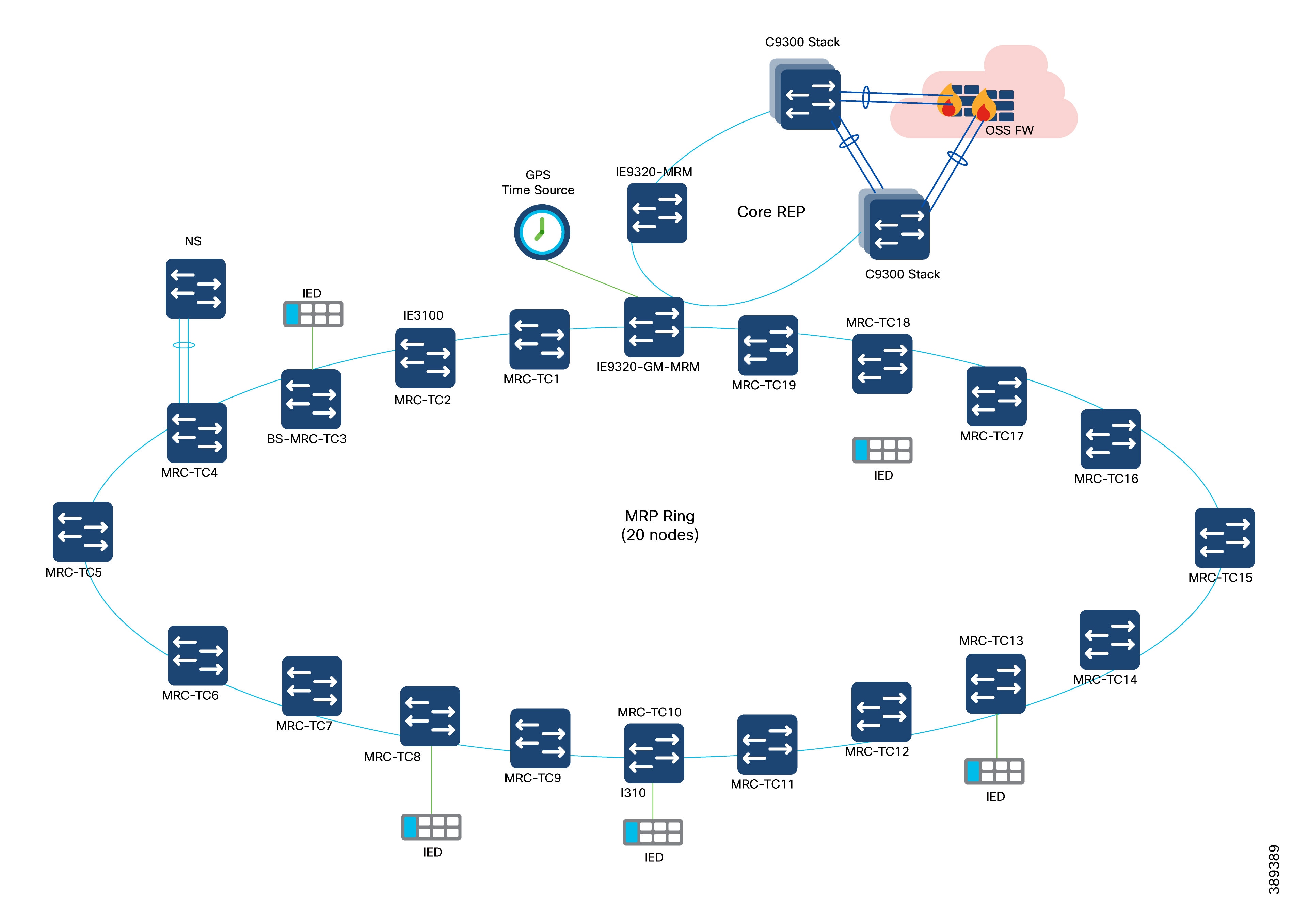
The MRM initiates and controls the ring topology to react to network faults by sending control frames on one ring port over the ring and receiving them from the ring over its other ring port, and conversely in the other direction. An MRC reacts to received reconfiguration frames from the MRM and can detect and signal link changes on its ring ports.
During normal operation, the network operates in the Ring-Closed state. To prevent a loop, one of the MRM ring ports is blocked, while the other port is forwarding. Most of the time, both ring ports of all MRCs are in the forwarding state. With this loop avoidance, the physical ring topology becomes a logical stub topology.
MRP Ring Design Considerations
● Cisco IE9300 Rugged Series Switches in the turbine operator network acts as MRP ring manager with higher priority value in MRA configuration and default MRP profile (200ms)
● Cisco IE3100 Series switches (up to 20 nodes) acting as turbine base switches are configured in default MRA role with default priority value; these base switches transition to MRP client role during MRM election process, since IE9300 ring aggregation switch is elected as MRM due to its high priority
● It is recommended to configure the default MRA role in all the IE switches in the MRP ring for better ring convergence performance
● Turbine nacelle switch connects to turbine base switch (MRC) in the MRP ring using default STP with port channel link for redundancy
● In cases of multiple MRP rings aggregated to OSS IE9320 switches, a separate admin VLAN is recommended for each ring with different MRP domain name and ID.
Refer to the following link for more details on MRP.
Turbine SCADA network timing synchronization
Precision Time Protocol (PTP) is defined in IEEE 1588 as Precision Clock Synchronization for Networked Measurements and Control Systems, and was developed to synchronize the clocks in packet-based networks that include distributed device clocks of varying precision and stability. PTP is designed specifically for industrial, networked measurement and control systems, and is optimal for use in distributed systems because it requires minimal bandwidth and little processing overhead.
Timing precision improves network monitoring accuracy and troubleshooting ability. In addition to providing time accuracy and synchronization, the PTP message-based protocol can be implemented on packet-based networks, such as Ethernet networks. The benefits of using PTP in an Ethernet network include:
● Low cost and easy setup in existing Ethernet networks
● Limited bandwidth is required for PTP data packets
For more details on PTP.
PTP is supported over MRP according to IEC standard 62439-2 to achieve fast convergence in ring network topology for Industrial Automation networks.
PTP over MRP is supported on:
● IE9300-Manager, having 12 rings, with each ring consisting of 20 nodes spanning over a length of 20kms.
● Network using QoS (COS 6 / DSCP EF 46).
● Copper and SFP ports.
● Time error deviation of less than 10 microseconds at 50% link utilization between the head end and the host in case of an MRP ring break.
Table 13 lists the PTP over MRP supported configurations:
Table 13. PTP over MRP supported profiles on Cisco IE9300 Series Switch
| Device |
PTP clock |
PTP profile |
MRP mode |
MRP convergence |
| IE9300 |
Boundary/Grand Master Boundary (GMC-BC) |
Default (IEEE 1588 v2) |
Manager |
200ms 500ms |
| IE3100 |
Transparent Clock |
Default (IEEE 1588 v2) |
Client |
200ms 500ms |
PTP over MRP Design Considerations
● In the turbine operator network MRP ring of up to 20 nodes, as shown in Figure 55, PTP default profile with Boundary/Grandmaster Clock (GMC-BC) is configured on IE9320 MRP ring manager/aggregation switch in the OSS network.
● Turbine base IE3100 series switches (MRCs) in the MRP ring are configured in default End-to-End transparent clock role.
● The grandmaster clock is a network device physically attached to the server time source. All clocks are synchronized to the grandmaster clock.
● Within a PTP domain, IE9320 switch acting as the grandmaster clock, is the primary source of time for clock synchronization using PTP. The grandmaster clock usually has a precise time source, such as a GPS or atomic clock. When the network does not require any external time reference and only needs to be synchronized internally, the grandmaster clock can free run.
● The role of transparent clocks (TC) in a PTP network is to update the time-interval field that is part of the PTP event message. This update compensates for switch delay and has an accuracy of within one picosecond.
● Intelligent Electronic Devices (IEDs) connected to turbine network which requires time precision, acts as PTP Ordinary Clock (OC) and its PTP clock is synchronized to grandmaster clock.
● PTP messages over MRP ring are transmitted using a dedicated (non-native) VLAN in the MRP ring.
The wind farm turbine operator network consists of different kinds of switches with different feature sets. A QoS model is important to guarantee network performance and operation by streamlining traffic flow, differentiating network services, and reducing packet loss, jitter, and latency.
Note: The reference QoS design recommended in this section, is based on the SCADA and other OT data traffic flows in the turbine operator network as defined by the turbine operator’s priority of data traffic for different traffic types available in the network.
● Cisco IE3400 and IE3100 switches in the TSN and FSN support one priority queue, seven class based queues, and two QoS thresholds (1P7Q2T) at each egress interface. However, depending on the turbine operator network SCADA and other OT traffic flows and its priority, traffic mapping at egress queues in the IE switches is performed as per the QoS design shown in Figure 56, by using 4 traffic classes and egress queues
● Ingress traffic classification is based on IP ACLs (or IP address of the source device) depending on the traffic type and mark the DSCP value for the ingress traffic at IE switch
● DSCP values of EF, CS4, CS2 and default marking is done at ingress for critical, high priority, medium and low priority traffic flows respectively for the traffic from various SCADA devices in the turbine operator network
● Each egress interface in the TSN and FSN in turbine operator network is mapped with a queuing policy, as per the QoS design in Table 10.
● Strict priority queueing is considered for critical devices or LLQ traffic with low buffer queue size (to ensure priority treatment over other classes of traffic) in case of network congestion and remaining bandwidth is shared for other classes of traffic.
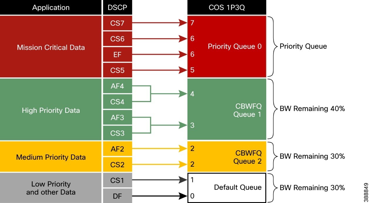 |
Table 14 lists the four traffic classes in a wind farm turbine operator network and the corresponding recommended ingress and egress classification, bandwidth and QoS treatment.
Table 14. Turbine Operator Network traffic classes, Bandwidth, and QoS Requirements
| Class |
DSCP |
PHB |
CoS |
Queue Type |
Assigned BW |
Queue Limit |
Devices |
| Class 0 (GOLD) |
40–63 |
EF, CS5, CS6, CS7 |
5, 6, 6, 7 |
LLQ (Strict Priority) |
— |
48 |
Critical devices data traffic |
| Class 1 (SILVER) |
24–39 |
CS3, CS4 |
3, 4 |
CBWFQ |
BW Remaining 40% |
48 |
High priority devices data traffic |
| Class 2 (BRONZE) |
16–23 |
CS2 |
2 |
CBWFQ |
BW Remaining 30% |
48 |
Medium priority devices data traffic |
| Default (CLASS-DEFAULT) |
0–15 |
CS0, CS1 |
0, 1 |
Default |
BW Remaining 30% |
272 |
Medium priority devices data traffic |
Network Management and Automation
This chapter includes the following topics:
● Device Discovery and Onboarding
● FAN REP Ring Provisioning using Catalyst Center REP Automation Workflow
● Day N Operations and Templates
Catalyst Center offers centralized, intuitive management that makes it fast and easy to design, provision, and apply policies across your network environment. The Cisco Catalyst Center GUI provides network visibility and uses network insights to optimize network performance and deliver an enhanced user and application experience. This guide focuses on a non-Software Defined Access (SDA) or a non-fabric design. A lack of network health visibility to network administrators, and manual maintenance tasks such as software upgrades and configuration changes are some of the common network challenges in an offshore wind farm network. Cisco Catalyst Center addresses these issues.
We recommend that Cisco Catalyst Center be placed as an application in the control center, but the final decision on location should be made considering your specific requirements.
Benefits of Cisco Catalyst Center include:
● As a single pane-of-glass, Cisco Catalyst Center network management performs critical functions to maintain the operational status of a network environment. These critical functions include assurance and monitoring of the production network, guided remediation of identified problems, and device replacement.
● Automated provisioning of network device configuration software updates and lifecycle management.
● Simplified network security policy deployment integrating with Cisco ISE. Key considerations when adding the Cisco Catalyst Center include the following:
● Catalyst Center requires connectivity to all network devices that it manages. All devices that need to be discovered and monitored should have an assigned IP address that is routable and able to reach the Cisco Catalyst Center.
● Catalyst Center requires internet connectivity for licensing information and updates. We recommend using a Smart License proxy. We also recommend that you allow secure access via the proxy service only to URLs and fully qualified domain names that are required by the Cisco Catalyst Center. For more information see Catalyst Center Security Best Practices Guide.
● If there is a firewall between Catalyst Center and managed devices, ensure that the required ports are allowed on the firewall. See “Required Network Ports” in Catalyst Center Second-Generation Appliance Installation Guide for a list of network ports that are required to be allowed on the firewall.
● Latency should be 100 ms or less to achieve optimal performance for all solutions that are provided by the Cisco Catalyst Center. The maximum supported latency is 200 ms RTT. Latency from 100 ms through 200 ms is supported, although longer execution times could be experienced for certain functions, such as inventory collection and other processes that involve interactions with managed devices.
● Cisco ISE must be deployed with a version that is compatible with Cisco Catalyst Center. See Compatibility Information.
Some known limitations of Cisco Catalyst Center include the following:
● Cisco Catalyst Center does not support managing network devices with management IP address behind a network address translation (NAT) boundary.
● Firewalls running Cisco Secure Firewall Threat Defense software are not supported on Cisco Catalyst Center. However, devices that are connected behind an industrial firewall can be provisioned and managed by Cisco Catalyst Center.
● FAN REP ring provisioning using REP automation workflow is supported by Cisco Catalyst Center. However, the ring of rings (also known as a subtended ring) REP provisioning is not automated in Cisco Catalyst Center workflows. We recommend using the Day-N template feature in Cisco Catalyst Center for all day N configurations and subtended TAN REP ring provisioning.
● Cisco Catalyst Center cannot manage products from third-party vendors.
Figure 56 illustrates the Cisco Catalyst Center features that are used in this wind farm solution.
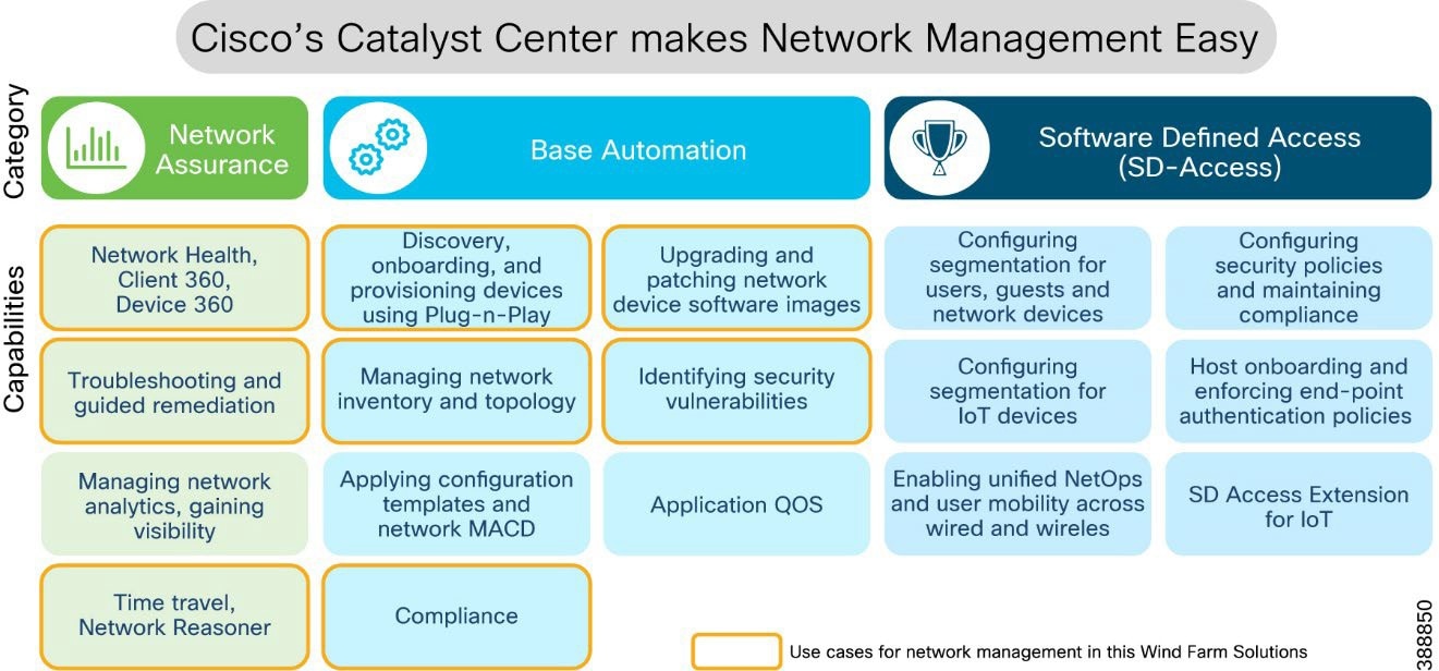 |
Figure 57 provides a flow diagram of Catalyst Center device settings, discovery, onboarding, and provisioning operations to manage wind farm network devices and endpoints.
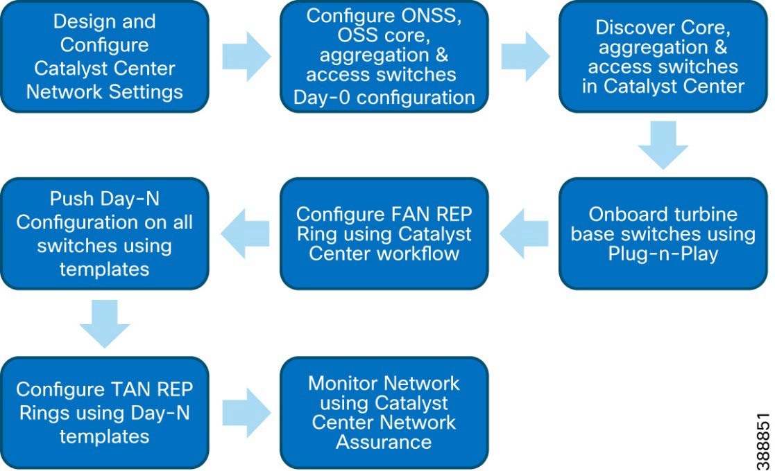 |
Device Discovery and Onboarding
This section describes the prerequisites for using Catalyst Center to discovery, provisioning, and network assurance features. It also covers offshore wind farm day 0 network provisioning, device discovery, and onboarding.
● The Cisco Catalyst Center appliance and software have been installed. Those topics are covered in more detail in Offshore Wind Farm Solution Implementation Guide.
● The Cisco Catalyst Center assigns users to roles that determine what types of operations a user can perform in the system. Users that need to provision the network should use the Network-Admin-Role. Only Cisco Catalyst Center system administrators should use the Super-Admin-Role.
● Define a network hierarchy by creating sites. Sites group devices by physical location, function, or both in a network. The network hierarchy represents your network locations. It allows for a hierarchy of sites, which contain areas, and areas contain buildings and floors. We refer to areas, buildings, and floors as site information. It is possible to create site information to easily identify where to apply design settings or configurations. A site on Cisco Catalyst Center determines which network settings, software images, and customized templates are applied to a device. We recommend that you create a network hierarchy in Cisco Catalyst Center based on area, site, and building name per different places in the network. For example, sites, areas, and buildings could be named CC/WAN/ONSS/OSS, Infra/Core/DMZ, and so on.
● Configure network settings that apply to created sites, including settings for device credentials, DHCP, and NTP servers. These network settings may be applied to devices that belong to a site as part of automation workflows.
● Create network profiles. For switches, network profiles link configuration templates to sites.
A network profile is a key concept in Catalyst Center and is used to standardize configurations for routers, switches, and WLCs in one or more sites. A network profile is used to assign configuration templates to devices based on their site information, device product family, and associated tags. For devices that require similar configuration, a template helps to reduce configuration time by enabling configuration re-use and using variables and logic statements as placeholders for any unique settings per device.
● We recommend that you manage software images within the Cisco Catalyst Center image repository for network infrastructure upgrades. Cisco Catalyst Center stores all unique software images according to image type and version. It is possible to view, import, and delete software images.
● Establish network connectivity between Cisco Catalyst Center in the control center and ONSS, OSS Core, access, and FAN aggregation switches in the wind farm network so that these devices can reach the Cisco Catalyst network. The switches in the ONSS, OSS, and FAN require initial manual configuration to be discovered and added into Cisco Catalyst Center inventory.
● The OSS and ONSS switches in a wind farm network are discovered and added to the Cisco Catalyst Center manually. Therefore, these switches require day 0 configuration using the device CLI to be discovered and added to the Cisco Catalyst Center inventory.
● Day 0 CLI configuration on these manually added core, aggregation, and access switches in the OSS and ONSS involve configuration of basic SSH, SNMP, and CLI credentials, and the routing configuration that is needed to connect to Cisco Catalyst Center in a control center.
● Turbine base switches and nacelle switches (Cisco IE3400s) are connected to a FAN aggregation switch stack and are onboarded using the Catalyst Center plug-and-play (PnP) feature.
Device Plug-n-Play Onboarding Using Catalyst Center
Turbine base switches and nacelle IE3400 switches are onboarded one-by-one (in a linear topology depending on the ring size) using the Catalyst Center plug-n-play feature. PnP onboarding considerations for turbine base switches and nacelle switches include the following:
● A turbine base switch connected to a FAN aggregation Catalyst 9300 switch stack is initially onboarded with zero touch by configuring Cisco Catalyst Center as a PnP controller, the Catalyst 9300 as a PnP startup device (also called a seed device), and a central DHCP server in the OSS infrastructure network or control center.
● The next turbine base switch in a FAN is connected linearly to the previous turbine’s base switch, which already is onboarded into Cisco Catalyst Center. This time, the uplink base switch acts as a PnP startup device for the newly-connected base switch and initiates the PnP process on the newly connected base switch.
● Similarly, all switches in FAN and TAN must be PnP onboarded (in order around the ring) into Cisco Catalyst Center using the previously onboarded uplink switch as the PnP startup or seed device.
FAN REP Ring Provisioning using Catalyst Center REP Automation Workflow
The Cisco Catalyst Center REP configuration workflow feature automates the provisioning of multiple IE switches in a ring topology. The ring topology is set up though a physical connection between two IE (base) switches that are onboarded into the Cisco Catalyst Center through PnP. The Cisco Catalyst Center non-fabric REP automation workflow feature considers a Catalyst 9300 switch stack as a REP edge device to form a closed REP ring with the IE switches that are connected to the same Catalyst 9300 switch stack.
Step-by-step instructions for configuring a REP ring using the Catalyst Center REP provisioning workflow for the FAN IE ring is discussed in Cisco Wind Farm Solution Implementation Guide.
REP Ring Design Considerations, Limitations, and Restrictions
● Only new REP ring (greenfield) deployments are supported. An existing REP ring topology, if any (one may have been configured using Day-N templates), in a wind farm FAN cannot migrated to a new REP ring configuration using the Cisco Catalyst Center REP automation feature.
● Considering the Catalyst 9300 switch stack as the STP root bridge, a maximum of 20 nodes (including Catalyst 9300 switches and up to 18 IE switches) in a stack is supported in a ring with default STP ring parameter values.
● A switch that is connected in a REP Ring cannot be deleted from the Cisco Catalyst Center inventory until the REP ring that the switch is part of is deleted.
● Multiple rings within a REP ring are not supported. A ring of rings is not supported. For example, a sub ring within the turbine cannot be provisioned using the Catalyst Center REP workflow. See the following section for information about using Day-N templates to provision turbine sub rings.
Day N Operations and Templates
Cisco Catalyst Center provides an interactive template hub to author CLI templates. You can easily design templates with a predefined configuration by using parameterized elements or variables. After creating a template, you can use the template to deploy devices in one or more sites that are configured anywhere in your network. Templates allow you to define a configuration of CLI commands that can be used to consistently configure multiple network devices, reducing deployment time.
In the wind farm solution, the following day N configurations are pushed to devices using the templates features in Cisco Catalyst Center:
● Configuration of additional VRFs and VLANs.
● Configuration of TAN high availability REP ring (subtended REP ring of FAN ring).
● Configuration of NetFlow monitor and flow exporter for Cisco Secure Network Analytics flow collection.
● Network Device RMA operations that require configuration changes. For example, adding a new switch stack and pushing configuration in the OSS infrastructure.
Additionally, network devices lifecycle management, which includes running configuration compliance checks, guided troubleshooting, software image management (SWIM), and network assurance features are included in day N operations and management.
See Cisco Wind Farm Solution Implementation Guide for more information about Cisco Catalyst Center Network management day N provisioning and monitoring in the wind farm solution.
Cisco SD-WAN is an enterprise-grade WAN architecture overlay that enables digital and cloud transformation for enterprises. It integrates routing, security, centralized policy, and orchestration into large-scale networks. It is multitenant, cloud-delivered, highly automated, secure, scalable, and application-aware with rich analytics.
In the wind farm solution, Cisco SD-WAN is used to provision and manage the WAN. Cisco IR8340 or 8000 series routers that are deployed as WAN edge routers in the ONSS are managed by Cisco SD-WAN Manager, a component of Cisco SD-WAN. The management of WAN edge routers and control center WAN headend routers is done by using Cisco SD-WAN.
For detailed design information about Cisco SD-WAN management, see the “WAN and SD-WAN Manager” section, in Substation Automation Design Guide—The New Digital Substation.
Security Design Considerations
This chapter includes the following topics:
● Security Approach and Philosophy
● Wind Farm Network Security Use Cases and Features
● Cisco Secure Network Analytics (Stealthwatch)
● Operational Technology Flow and Device Visibility using Cisco Cyber Vision
● Cisco Secure Equipment Access
● Turbine Operator Network Security Design
● NERC CIP Compliance Features and Guidance
Security Approach and Philosophy
Many wind farms increasingly form part of a country’s national critical infrastructure and as such should be protected.
There is a need for a cost-effective security model, especially one that provides easier deployment, maintenance, and troubleshooting, and improved stability and resiliency for wind farm operations.
Cyber security must be comprehensive and a fully integrated part of the overall network design. Any design should seek to minimize administrative overhead in cybersecurity deployment and operations.
The ability to identify all wind farm assets and their associated vulnerabilities, detect any new threats or anomalous behavior on the network, and monitor traffic on an ongoing basis greatly enhances the capability to minimize the cybersecurity overhead.
Improved security measures are necessary to become compliant with the North American Electric Reliability Corporation Critical Infrastructure Protection requirements (NERC CIP) or the NIS2 directive in the EU.
The following fundamental principles must be adopted by the asset network operator to ensure secure systems:
● Visibility of all devices in the wind farm networks: Traditionally, enterprise devices such as laptops, mobile phones, printers, and scanners are identified by the enterprise management systems when these devices access the network. This visibility can be extended to all devices on a wind farm network.
● Segmentation and zoning of the network: Segmentation is a process of bounding the reachability of a device and zoning is defining a layer where all members in that zone have identical security functions. Designing zones in a network is an organized method for managing device access within a zone and controlling communication flows across zones. Segmenting devices further reduces the risk of an infection spreading if a device is subjected to malware.
● Identification and restricting data flows. All devices in a wind farm network (operational network) and enterprise (IT-managed network) must be identified, authenticated, and authorized. The network must enforce a policy when users and industrial automation and control system (IACS) assets attach to the network.
● Detection of network anomalies: Any unusual behavior in network activity must be detected and examined to determine if the change is intentional or due to a malfunction of a device. Detecting network anomalies as soon as possible gives turbine operators the ability to remediate abnormalities in the network quickly, which can help reduce possible downtime.
● Detection and mitigation of malware: Unusual behavior by an infected device must be detected immediately, and the security tools should allow remediation actions for an infected device.
● Implementation of appropriate firewalls: Traditional firewalls are not typically built for industrial environments. There is a need for a firewall that can perform deep packet inspection on industrial protocols to identify anomalies in IACS traffic flows.
● Hardening of the networking assets and infrastructure: This critical consideration includes securing key management and control protocols, such as using SSH instead of Telnet for remote sessions, using simple network management protocol (SNMP) V3, and using HTTPS instead of HTTP for device GUIs.
● Monitoring of automation and control protocols: It is important to monitor the IACS protocols for anomalies and abuse.
● Adhering to security standards: In the 1990s, the Purdue Reference Model and ISA 95 created a strong emphasis on architecture that uses segmented levels between various parts of a control system. This approach was further developed in ISA99 and with IEC 62443, which brought focus to risk assessment and business processes. Any security risk assessment identifies which systems are defined as critical control systems, non-critical control systems, and non-control systems.
Figure 58 shows a sequence of steps for implementing network security in an offshore wind farm network.
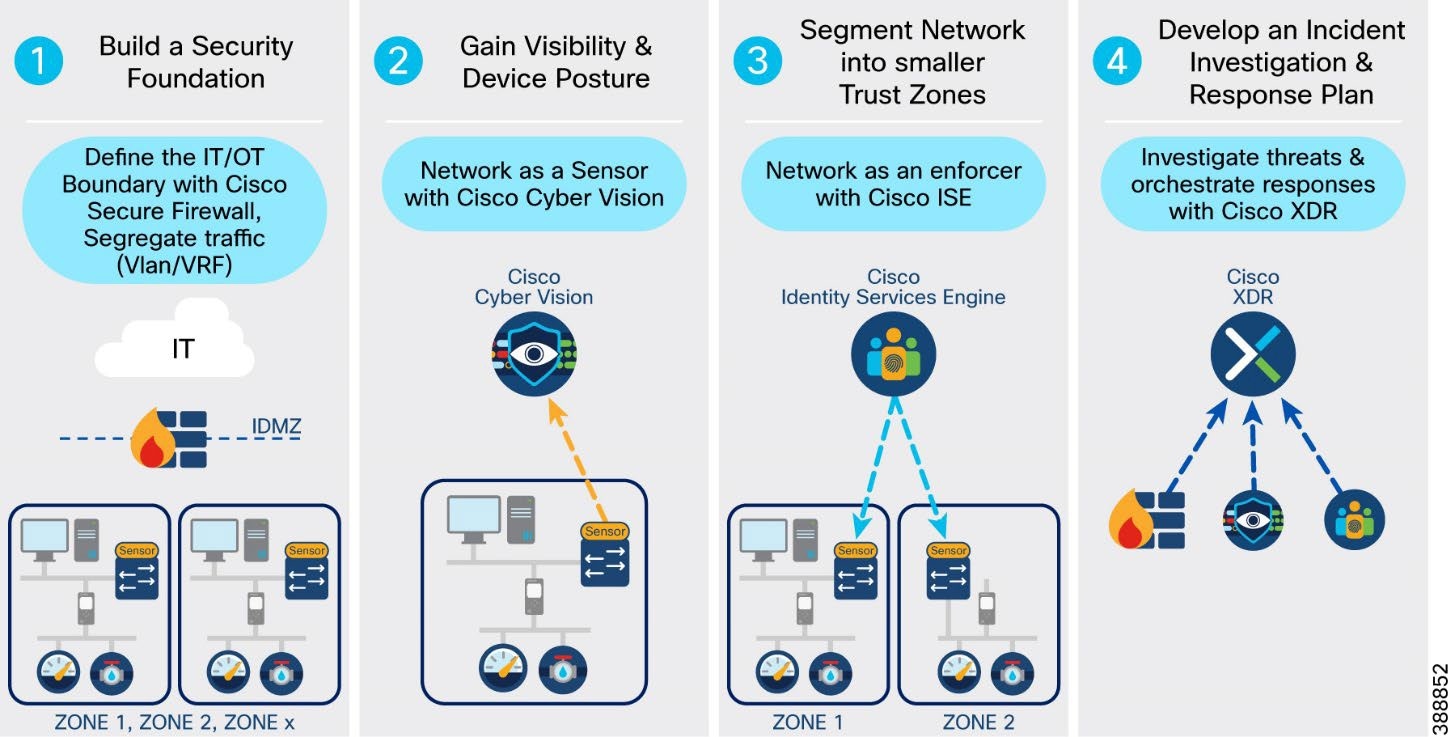 |
Steps to implement network security in an offshore wind farm:
● Creating zones and conduits: Using good design techniques provides the foundation for any cybersecurity architecture. Many standards (such as IEC62443 and NERC CIP) reference the concepts of segregating devices and controlling traffic flows between those devices. VLANs and VRFs create logical zones and segregate traffic and devices, thus restricting data flows between devices. Firewalls provide control points where traffic can be inspected, and access restricted to only the traffic flows that are desired (least privilege). Where firewalls are not required, access control lists provide simple access control for traffic flows and define secure perimeters for the various subsystems. This Cisco Validated design provides the validated topologies to provide this baseline.
● Asset discovery and traffic flow visibility: Cisco Cyber Vision provides the ability to discover assets that are connected to the network and to determine how these assets are communicating. This visibility of assets and the traffic flows between them allows an asset operator to make informed decisions on allowed and undesirable traffic flows. This visibility also allows the asset operator to create a baseline for what is considered normal behavior and have alerts configured for any changes to the network assets or traffic flows. It is also important to have visibility of traffic flows north-south to the OSS and ONSS and externally to the data center.
● Dynamic segmentation: Cisco Identity Services Engine (ISE) utilizes Cisco TrustSec to logically segment control system networks. Cisco TrustSec classification and policy enforcement functions are embedded into Cisco switching, routing, wireless LAN, and firewall products. At the point of network access, a Cisco TrustSec policy group, called a security group tag (SGT), is assigned to an endpoint, typically based on that endpoint’s user, device, and location attributes. The SGT denotes the endpoint’s access entitlements, and all traffic from the endpoint carries the SGT information. The SGT is used by switches, routers, and firewalls to make forwarding decisions. Cyber Vision can be integrated directly with ISE. Cyber Vision shows assets and their communications in maps that operations teams can easily relate to their industrial processes. This information gives administrators the opportunity to group assets into logical zones based on the business roles that these devices have on the network. ISE can use the asset groupings to implement more granular policies in the network switches that support SGTs. As organizations implement micro segmentation policies, groups can be made smaller, and conduits can be monitored to ensure that policies do not interfere with daily operations of the business.
● Threat detection and response: The final consideration for securing the offshore wind farm network is the ability to detect and respond to potential threats. The NIST cybersecurity framework outlines five core cybersecurity principles—identify, protect, detect, respond, recover. The first three steps above cover the capabilities that are needed to identify the people and assets in your network, protect them using network policies, and detect the occurrence of a cybersecurity event. The respond function supports the ability to contain the effect of a potential cybersecurity incident. Cisco Extended Detection and Response (XDR) is an incident investigation and response platform that aggregates intelligence from both Cisco security products and third-party sources. This intelligence enables security analysts to identify whether observable items such as file hashes, IP addresses, domains, and email addresses are suspicious. When you start an investigation using Cisco XDR, context is automatically added from integrated Cisco security products, so you know instantly which of your systems was targeted and how. Cisco XDR obtains relevant information from intel sources and security products, displaying results in seconds. Cisco XDR also provides security operations teams with the ability to act immediately by triggering custom workflows or continue their investigation with the tools provided.
Using Cisco TrustSec on IE switches with ISE to enforce security policies at the OSS layer 3 boundary (macro segmentation) provides an easy path to move from manually configured access control lists to a centralized policy-based network. Security policies are configured centrally on ISE and pushed into the network. Cyber Vision shares the discovered asset attribute information to ISE, as ISE does not natively contain industrial asset information.
Security policies and traffic rules are defined based on zones. For example, a security zone can be determined by VLANs, Ports or locations etc.
Figure 59 shows an example micro-segmentation security policy based on IE rings, HMI. and SCADA devices.
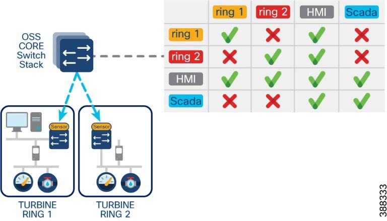 |
Using micro segmentation, operations personnel can group assets on Cyber Vision into more meaningful groups. These group names are pushed to ISE (group tag attributes are shared from Cyber Vision to ISE). Subsequently, ISE can match a policy of the same name (preconfigured by IT) and ISE pushes the required SGTs and dACLs to the appropriate switches in the network.
This approach allows a deep level of segmentation of devices into smaller groups based on their roles rather than their VLANs. membership.
Figure 60 shows an example industrial network topology in Cisco Cyber Vision, its security policy matrix in ISE, and the application of a security policy (dACL) based on SGT and VLAN.
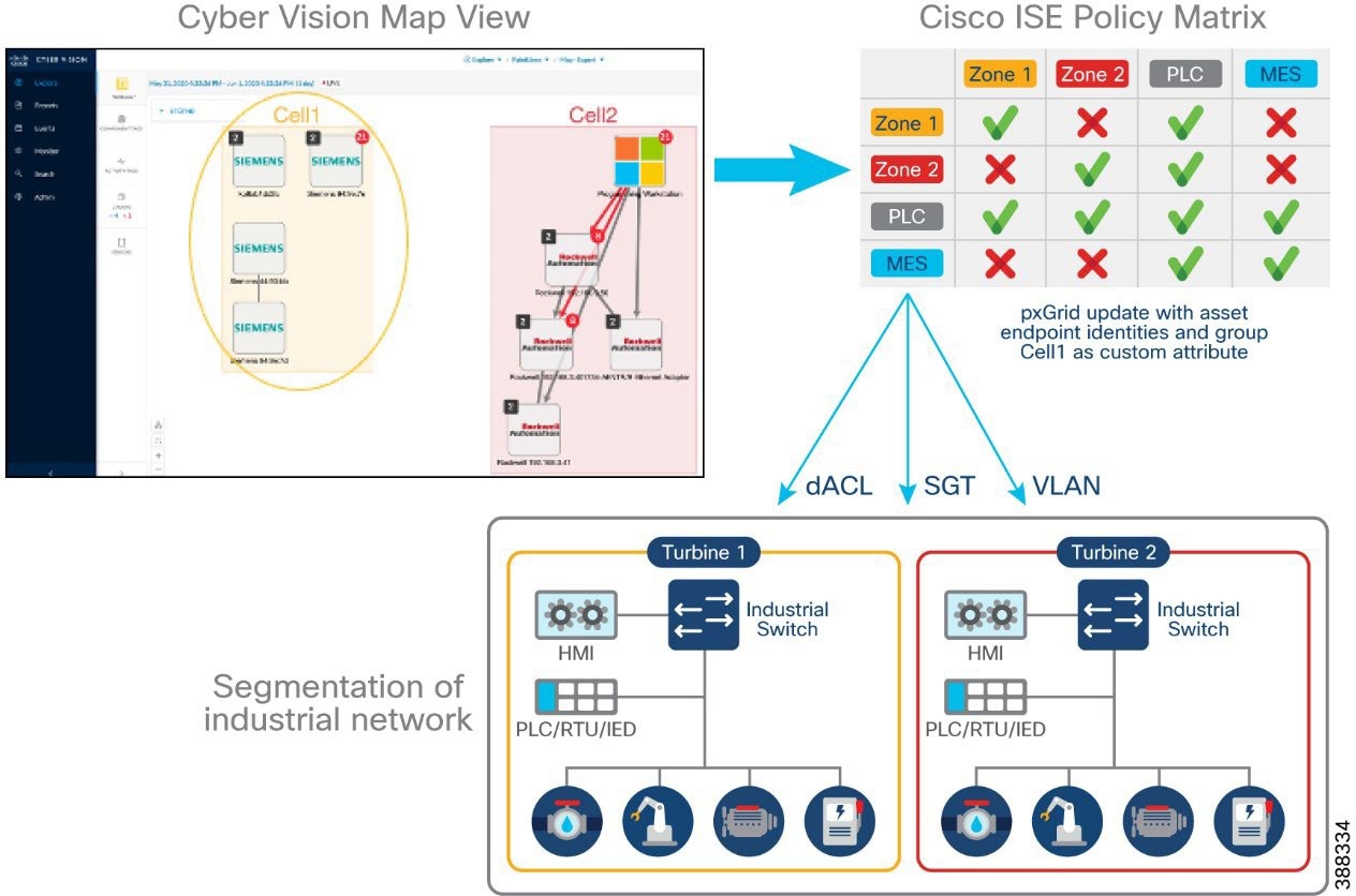 |
Wind Farm Network Security Use Cases and Features
This section describes the wind farm network security use cases for various services, applications, equipment, and devices (also known as wind farm actors) that are found in different places within the architecture. Security must be comprehensive and fully integrated with the overall network architecture. Wind farm network security design has many commonalities with various other industry solutions such as substation automation, industrial automation, and so on. The objective is to promote the use of common security designs and principles across solutions, where possible.
Table 15 lists various wind farm network security use cases, solution design considerations, and security features to be adopted to address security challenges in the network.
Table 15. Wind farm security use cases
| Security Use Case |
Security Solution |
Security Features |
| Network segmentation and zoning |
Define macro and micro network segments: VRF, VLAN, SGT, SGACL |
● Macro segmentation (virtual routing and forwarding and VLANs)
● Network logically separated into smaller network segments to be managed independently
● Micro segmentation (scalable group tag)
● Allow policy control within a VRF/VLAN
• Segments map to an SGT group (user, application, device, and so on)
● Segments allows the group information to be carried from the source to the destination, allowing policies to be applied on the group
● Designing zones is an organized method for managing device access within a zone and to control communication flows across zones
|
| Traffic and asset visibility |
Detect IT and OT traffic flows and assets: Cisco SNA (Stealthwatch), Cisco Cyber Vision |
● NetFlow and Cisco SNA for flow collection and anomaly detection
● Cisco Cyber Vision Network sensors for OT asset visibility and flow detection
|
| IT and OT operational insight |
Gain visibility and monitor network operations: Cisco Identity Services Engine (ISE), Cisco Stealthwatch Management Console (SMC), Cisco Cyber Vision Center (CVC) |
● AAA identity services
● Network management
● Asset inventory
● Anomaly detection
● Deep packet inspection (DPI)
● Centralized analytics and data visualization
|
| Data encryption, threat detection and protection |
Protect network edges: Firewall and intrusion detection at DMZ, Network edge firewall (Cisco Secure Firewall), Secure IPSec tunnels for WAN Edge routers connectivity over public backhaul, MACsec Encryption on turbine operator network rings |
● Access control lists (ACLs)
● Intrusion detection systems (IDS) and intrusion prevention systems (IPS)
● Advanced malware protection
● VPN services
● Wide area VPN and encryption (IPsec)
● MACsec layer 2 switch-to-switch link encryption enabled between Catalyst 9300, IE9320 and IE3400 switches in the turbine operator network
|
| Secure remote access |
Secure remote connectivity: Remote VPN service, Control center firewall as VPN concentrator |
● IPSec and SSL VPN encryption
● Cisco AnyConnect VPN Mobility Client
|
| User and endpoints authentication and access control |
Secure edge and device connectivity |
● Layer 2 security features (port security, DHCP snooping, ARP inspection, storm control, and so on)
● 802.1X authentication
● MAC authentication bypass (MAB) authentication
● QoS marking
● NetFlow
● Cisco TrustSec tagging (SGT) and policy (SGACL) enforcement
|
Network segmentation is the practice of dividing a large network into several smaller subnetworks that are isolated from one another.
Macro segmentation:
● Network is logically separated into smaller network segments that are managed independently. Virtual routing and forwarding (VRF) provides a separate routing table for each of the network zones that requires separation from other network zones. VRFs provide layer 3 segmentation.
● Network traffic for each segment (VLAN) is segregated (unless a network policy defines otherwise). VLANs provide layer 2 segmentation.
● When a network or security issue occurs within the network, the issue is contained within a segment. This means that a security risk is minimized to a particular segment.
Micro segmentation:
● Allows security and policy control within a VRF or VLAN.
● A segment maps to an SGT group (user, application, device, and so on). Scalable groups (SG) allow security policy definitions for allowing and denying group communication, SGT propagation, and policy enforcement in the network edge.
● Define group access policy based on macro and micro segments
● Define whether VRF to VRF communications are allowed.
● Define group communication based on SGTs and SGACLs.
See Table 9, VLANs and VRFs in the Wind Farm Network Design, for a list of VLANs and VRFs in the wind farm network that is validated in this solution.
Advantages of Network Segmentation
● Improved security: Network traffic can be segregated to prevent access between network segments.
● Better access control: Allows users to access only specific network resources.
● Improved monitoring: For login events, monitoring allowed and denied internal connections, and detecting suspicious behavior.
● Improved performance: With fewer hosts per subnet, local traffic is minimized. Broadcast traffic can be isolated to a local subnet.
● Better containment: When a network issue occurs, its effects are limited to the local subnet.
Cisco Secure Network Analytics (Stealthwatch)
Network visibility is the foundation for the continuous monitoring that is needed to gain awareness of what is happening in a network. Complete visibility is critical to making proactive decisions and getting to resolutions as quickly as possible. Network threat defense prevents threats from an external network entering the internal network and identifies suspicious network traffic patterns within a network.
Cisco Secure Network Analytics Enterprise (formerly Cisco Stealthwatch) provides network visibility and applies advanced security analytics to detect and respond to threats in real time. Using a combination of behavioral modeling, machine learning, and global threat intelligence, Cisco Secure Network Analytics Enterprise can quickly, and with high confidence, detect threats such as command-and-control (C&C) attacks, ransomware, DDoS attacks, illicit crypto mining, unknown malware, and insider threats. With a single, agentless solution, you get comprehensive threat monitoring across network traffic, even if the traffic is encrypted.
Cisco Secure Network Analytics enlists the network to provide end-to-end visibility of traffic. This visibility includes knowing every host—seeing who is accessing what information at any point. It is important to know what normal behavior for a particular user or host is and to establish a baseline from which you can be alerted to any change in the user or host behavior the instant it happens.
Cisco Secure Network Analytics offers many advantages, including:
● Network visibility: Provides comprehensive visibility in a private network and the public cloud, without deploying sensors everywhere.
● Threat detection: Constantly monitors the network to detect advanced threats in real time. Using the power of behavioral modeling, multilayered machine learning, and global threat intelligence, Cisco Secure Network Analytics reduces false positives and alarms on critical threats affecting your environment.
● Incident response and threat defense: Protects network and critical data with smart and effective network segmentation. Uses secure network analytics integration with Cisco Identity Services Engine (ISE) to create and enforce policies, and keep unauthorized users and devices from accessing restricted areas of the network.
Flexible NetFlow Data Collection
NetFlow is a network protocol system created by Cisco that collects active IP network traffic as it flows in or out of an interface. NetFlow is now part of the Internet Engineering Task Force (IETF) standard (RFC 3954) as Internet Protocol Flow Information eXport (IPFIX, which is based on NetFlow Version 9 implementation), and the protocol is widely implemented by network equipment vendors.
NetFlow is an embedded instrumentation within Cisco IOS Software to characterize network operation. Visibility into the network is an indispensable tool for IT professionals. NetFlow creates flow records for the packets that flow through the switches and the routers that are in a network between end devices, and exports the flow records to a flow collector. The data collected by the flow collector is used by different applications to provide further analyses. NetFlow is primarily used for providing security analyses, such as malware detection, network anomalies, and so on.
The Cisco Industrial Ethernet (IE) 3x00 Series switches, Cisco Catalyst 9300, and Cisco Catalyst 9500 support full Flexible NetFlow. Each packet that is forwarded within a router or switch is examined for a set of IP packet attributes. These attributes are the IP packet identity or fingerprint of the packet and determine whether the packet is unique or like other packets.
Typically, an IP flow is based on a set of five and up to seven IP packet attributes. All packets with the same source or destination IP address, source or destination ports, protocol interface, and class of service are grouped into a flow and then packets, and bytes are tallied. This methodology of fingerprinting or determining a flow is scalable because a large amount of network information is condensed into a database of NetFlow information called the NetFlow cache.
With the release of NetFlow v9, a switch or router can gather additional information, such as ToS, source MAC address, destination MAC address, interface input, interface output, and so on.
As network traffic traverses a Cisco device, flows are continuously created and tracked. As the flows expire, they are exported from the NetFlow cache to the Secure Network Analytics Flow Collector. A flow is ready for export when it is inactive for a certain time (for example, no new packets are received for the flow) or if the flow is active (long lived) for a configured time. The active flow lasts longer than the configured active timer (for example, long FTP download and the standard TCP/IP connections). There are timers to determine whether a flow is inactive, or a flow is active (long lived).
We recommend that NetFlow monitoring be enabled in a wind farm network for security on all the interfaces in the network, including within the FAN and TAN switches interfaces to OSS infrastructure where application servers reside, and so on. Configuring NetFlow can be done using Cisco Catalyst Center templates, and is covered in detail in Cisco Wind Farm Solution Implementation Guide.
Cisco Secure Network Analytics for Windfarm Network Security
The main components of the Cisco Secure Network Analytics system are:
● Secure Network Analytics Flow Collector (SFC)
● Secure Network Analytics Management Console (SMC)
Note: The SFC or SMC resides on different virtual or hardware appliances.
The SFC collects NetFlow data from network devices, analyses it, creates a baseline for normal network activity, and generates an alert for any behavior that falls outside of the baseline. Based on the volume of traffic, there could be one or multiple SFCs in a network. The SMC provides a single interface for the IT security architect to get a contextual view of the entire network traffic. The SMC collects NetFlow information to gain visibility across all network conversations (north-south and east-west traffic) to detect internal and external threats. It also conducts security analytics to detect anomalous behavior.
The SMC has a Java-based thick client and a web interface for viewing data and configurations. The SMC provides the following:
● Centralized management, configuration, and reporting for up to 25 SFCs
● Graphical charts for visualizing traffic
● Acceleration of threat detection and incident response to reduce security risk
● Integration with ISE, providing visibility of device and user information
The SMC Network Security Dashboard provides security insights such as top alarming hosts, today’s alarms, flow collection trends, top applications in the network, and so on.
Because the SFCs are to be accessed by all endpoints in the wind farm network, we recommend that the SFC be deployed in the OSS infrastructure network and SMC in the control center network, as shown in Figure 61.
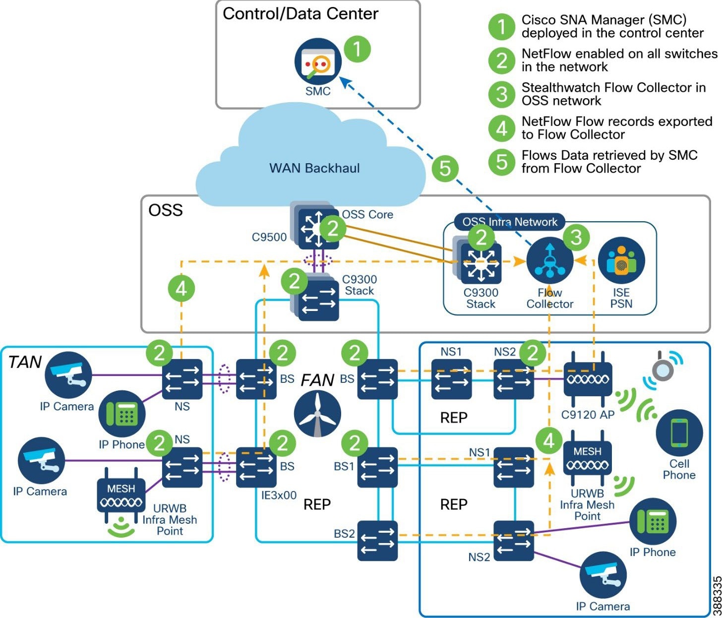 |
Important considerations when deploying a Secure Network Analytics system include the following:
● Secure Network Analytics is available as both hardware (physical appliances) and virtual appliances.
● Resource allocation for the SNA Flow Collector depends on the number of flows per second (FPS) that is expected on the network, the number of exporters (networking devices that are enabled with NetFlow), and the number of hosts that are attached to each network device.
● Data storage requirements must be taken into consideration, which again depends on the number of flows in the network.
● A specific set of ports needs to be open for the Secure Network Analytics solution in both the inbound and outbound directions.
See Cisco Secure Network Analytics System Configuration Guide for information about the installation of Secure Network Analytics, SFC scalability requirements, and data storage and network inbound and outbound ports requirements:
Cisco Secure Network Analytics for Abnormal Traffic Detection
A wind farm network engineer or security architect can use Cisco Secure Network Analytics with NetFlow enabled on Cisco Industrial Ethernet (IE3x00) switches in the ring, Cisco Catalyst 9300 or 9500 switches acting as FAN aggregation, and core switches to monitor the network flows in WF.
By integrating Secure Network Analytics and ISE, you can see myriad details about network traffic, users, and devices. Instead of showing just a device IP address, Cisco ISE delivers many key details, including username, device type, location, the services being used, and when and how the device accessed the network.
NetFlow is enabled on all wind farm networking devices to capture traffic flows, which are then sent to the SFCs. Flow records from the network devices are exported to SFCs in the OSS infrastructure network. The SMC retrieves the flow data from the SFCs and runs prebuilt algorithms to display the network flows. The SMC also detects and warns if there is any malicious or abnormal behavior occurring in the network.
Secure Network Analytics includes many machine learning algorithms that can assist a network security professional with detecting abnormal and malicious traffic in a network. It can detect abnormal behavior and provide the IP address of the device that is causing the issue. This information greatly simplifies the detection process.
Benefits of SNA in wind farm network include the following:
● Secure Network Analytics detects a possible infiltration or abnormal traffic activity using NetFlow in the wind farm network by raising an alarm under the High Concern index.
● SMC triggers an alarm whenever it detects abnormal or malicious activity on the network.
● Wind farm network security professionals respond to the alarms by planning remediation that involves further investigation and restricting access to the device that is causing the abnormal or malicious activity on the network.
● The device or user that is causing abnormal or malicious activity in the network is identified with the help of Cisco ISE, and the network security professional triggers a policy action to quarantine the device access in the network.
Operational Technology Flow and Device Visibility using Cisco Cyber Vision
For wind farms, SCADA with DNP3 or MODBUS protocol traffic in an OT VRF network is an example of an operational technology (OT) flow in the network. A Cyber Vision sensor deployment for OT flow and device detection shows different actors, such as the SCADA client, Cyber Vision Sensor, SCADA server, and Cyber Vision Center, that are involved in the network for OT traffic flow and device detection.
Cyber Vision Design Considerations
Cisco Cyber Vision gives OT teams and network managers full visibility into their assets and traffic flows. With this visibility, teams can implement security best practices, drive network segmentation, and improve operational resilience. Cisco Cyber Vision and ISE combined threat response helps to address many of the design requirements for visibility, anomaly detection, and mitigation.
The inline network sensors on Cisco IE3400 IE3300-X, Catalyst 9300, IR1101 devices, and the Cisco IC3000 Industrial Compute Gateway as a dedicated hardware sensor. The sensors are dedicated to capturing network traffic by using various SPAN features. The sensors then decode the SCADA and other OT protocols that are supported by Cyber Vision using the Cyber Vision deep packet inspection (DPI) engine.
Figure 62 illustrates the Cisco Cyber Vision two-tier architecture.
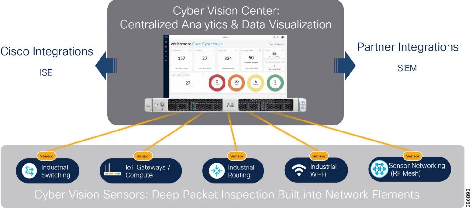 |
Cisco Cyber Vision design considerations in an offshore wind farm network include the following:
● A local Cisco Cyber Vision Center located in WF OSS infrastructure network to collect metadata from CV network sensors that are deployed across TAN and FAN.
● Local Center synchronizes with Cyber Vision Global Center located in a data center or control center.
● Cisco Cyber Vision Global Center feature allows synchronization of several local centers within a single repository.
● The Global Center aggregates local centers into a single application and presents a summary the activities of several centers.
● The collection network design: Consists of a separate VLAN for collection network and separate VLANs for OT traffic with a SPAN design as required for the sensor type.
Figure 63 illustrates the Cisco Cyber Vision design in the wind farm network architecture.
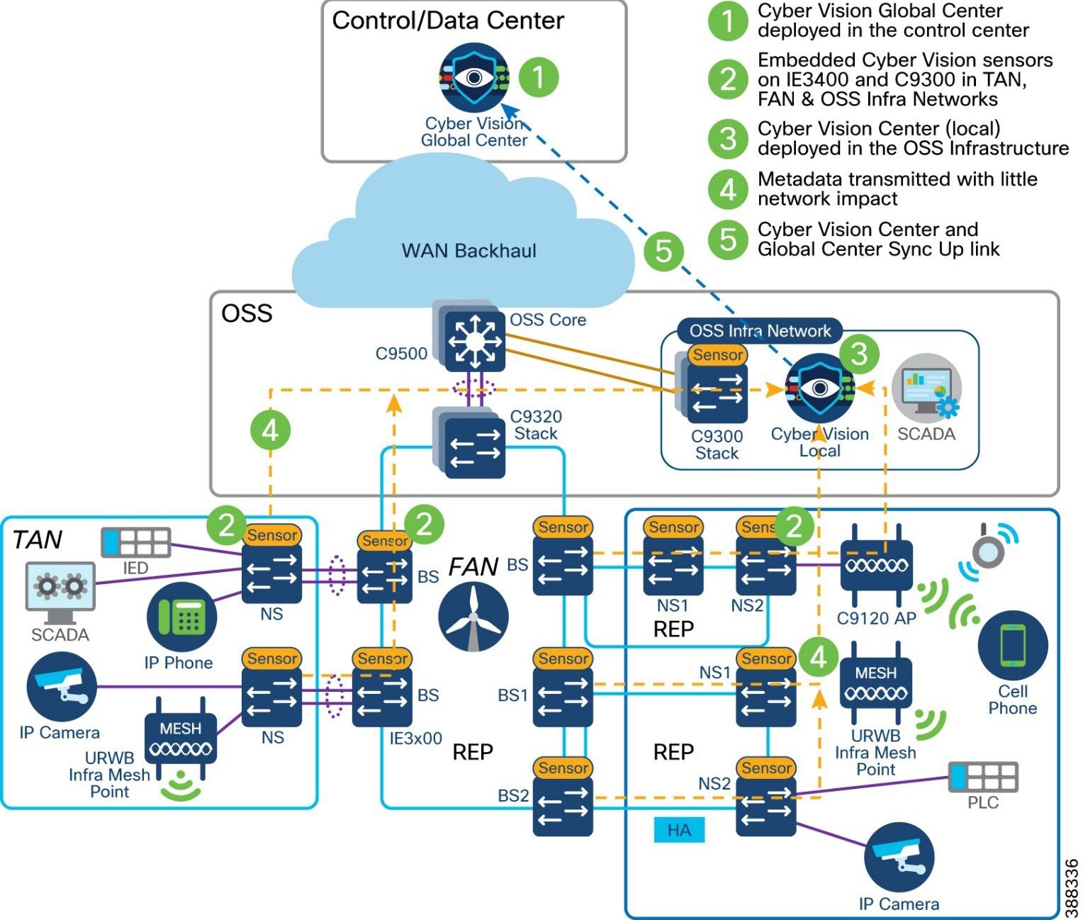 |
For more detailed information about Cyber Vision Global and Local Center deployments, see Cisco Cyber Vision Data Sheet.
Wind Farm Cyber Vision Network Sensors
Cisco IE3400 switches in a TAN and FAN and Catalyst 9300 switch in an OSS network act as Cyber Vision network sensor to capture OT protocol flows and messages in a wind farm network. For a list of supported OT protocols, see OT Protocols Support that follows.
The Cisco Cyber Vision sensor application hosted on Cisco IE3400 and Catalyst 9300 switches. The IOx architecture of these switches provides an internal AppGigabitEthernet1/1 interface that can be configured as either access or trunk mode and enables connectivity for the hosted application.
Currently, an IOx application interface must have VLAN ID configured even if the AppGigabitEthernet1/1 interface is configured as access mode. We recommend configuring the AppGigabitEthernet1/1 as a trunk interface for hosting the Cisco Cyber Vision sensor application. This application uses two interfaces, one for capturing traffic from the IE3400 switch physical interfaces and one for the Cisco Cyber Vision Center collection network.
The IE3400 may have multiple VLANs provisioned as part of a wind farm network segmentation. Different VLANs can also be provisioned to forward the traffic that is monitored on physical interfaces or VLANs of IE3400, forward the same traffic to the hosted sensor application for further processing, or enable connectivity from the sensor application to the Cisco Cyber Vision Center collection network interface.
The AppGigabitEthernet1/1 interface is a non-routed interface and the sensor application interprets source packets to be GRE encapsulated. For monitoring and forwarding packets in ERSPAN format to the sensor application, enable ERSPAN on the provisioned AppGigabitEthernet1/1 VLAN. IE3400 IOx application interface mapping depicts the logical mapping of physical interfaces and the hosted IOx application on the IE3400.
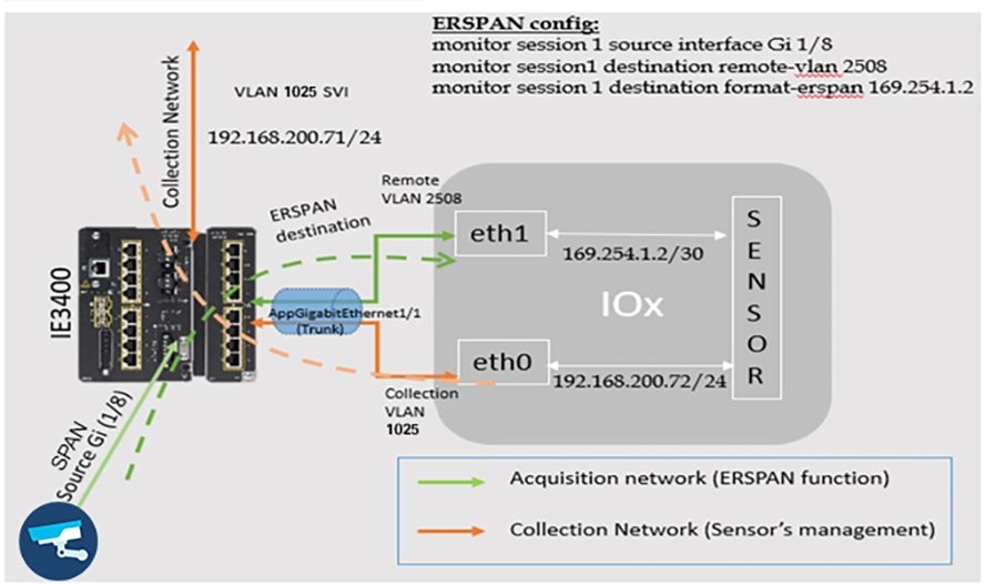 |
Table 16 lists the OT protocols that are supported by Cyber Vision in the wind farm network architecture.
Table 16. OT Protocols Supported by Cisco Cyber Vision for Wind Farms
| Protocols |
Type of Communication |
| MODBUS |
TCP/IP |
| DNP3 |
TCP/IP Serial over TCP raw socket |
| T101 |
TCP/IP |
| T101 to T104 |
T101 to T104 |
| OPC-UA |
TCP/IP |
For additional information about Cyber Vision 4.x protocol support, see Cisco Cyber Vision Protocol Support Data Sheet.
Wind Farm Asset Operators require secure, controlled, and auditable remote access to Operational Technology (OT) assets located in geographically distributed and often offshore turbine environments. Traditional VPN-based remote access exposes large network segments and conflicts with Zero Trust principles required for critical infrastructure environments.
Cisco Secure Equipment Access (SEA) provides a hybrid cloud-based Zero Trust Network Access (ZTNA) solution that enables secure, identity-based, policy-controlled access to specific OT assets and services without extending the OT network perimeter. Cisco Secure Equipment Access (SEA) is a hybrid cloud service that enables secure remote connectivity to OT assets via:
● Identity verification
● Policy-based authorization
● Application-level access control
● Encrypted proxy communication over TLS (TCP/443)
● Reverse tunnel architecture (no inbound firewall openings required)
SEA enables secure remote access to OT assets connected to wind turbines using the following protocols using a clientless (browser based) and agent based (SEA Plus) access methods:
● HTTP/HTTPS
● SSH
● RDP
● VNC
● Telnet
Cisco Cyber Vision’s SEA Architecture and Core Components
With Cyber Vision’s SEA, Cisco is solving the challenges of deploying ZTNA in industrial settings. In addition to secure remote access, the platform offers a complete set of capabilities to help protect industrial networks from cyberthreats:
● Comprehensive visibility into OT assets, their vulnerabilities, and communication activities
● OT risk management with smart scoring of asset vulnerabilities and detection of malicious traffic and abnormal asset behaviors
● Adaptive network segmentation to help protect operations by making it easy for OT and IT teams to work together in defining and enforcing access policies that will not disrupt production
● Self-service remote access to empower operations teams while enforcing least-privilege zero trust access policies to control risks from remote users
With Cyber Vision’s SEA, remote users just need a web browser to access remote OT assets in a wind farm. They connect to the SEA cloud portal, where they are authenticated and offered access only to the devices you choose, using only the protocols you specify, and only on the day and time you allow.
Figure 65 illustrates the SEA architecture and its core components and presents the logical architecture and protocol interaction model between remote users, the SEA Cloud, the SEA Agent, and OT assets.
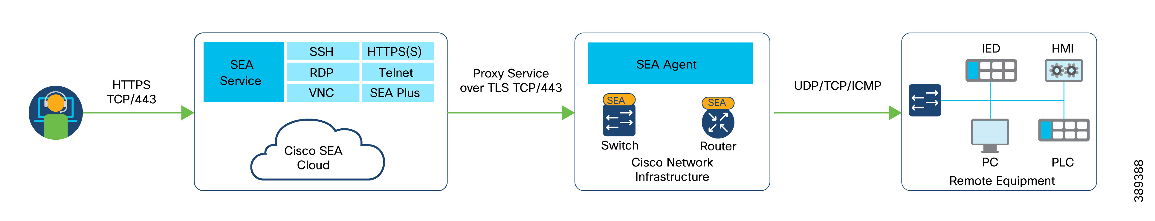
The SEA cloud portal is a ZTNA trust broker that handles policy definition and enforcement. Security teams now have a single interface to manage users, assets, and policies for all sites. It uses Cisco or third-party Identity Providers (IdP) to authenticate users, enforce Multifactor Authentication (MFA), and enable Single Sign-On (SSO).
Cisco SEA Agent is is a free software feature running in select Cisco industrial switches and routers. Not only does it eliminate the need for sourcing and deploying dedicated hardware, but it also allows for deployment of any number of gateways. SEA agent software is an IOx application, the virtualization environment offered by Cisco IOS® XE, Cisco’s networking operating system. It runs in a dedicated CPU core in the hosting device, which means SEA can access all the resources it needs with no impact on the performance of the switch or router.
Cisco Cyber Vision’s SEA in Wind Farm Network Design
Cyber Vision’s SEA is a cloud service that runs in Cisco network equipment, making it very simple to deploy and manage at scale. It empowers operations teams, vendors, and contractors to easily connect to remote OT assets. It lets organizations enforce least-privilege access policies based on identities and contexts. It is designed to be very simple to configure, so the line of business can easily create remote access credentials when needed while maintaining security controls and respecting security policies defined by the IT and security teams.
In Wind Farm Asset Operator’s turbine base and nacelle IE3400/IE3500 switches, a combined Cyber Vision Sensor (CV) and SEA IOx application is deployed using the Cyber Vision Center (local) in the OSS infrastructure network. CV Center in OSS enables Internet access to the combined CV+SEA IOx application via proxy to establish outbound connectivity to SEA Cloud service using TLS TCP connection, as shown in Figure 66. It is recommended to deploy combined CV and SEA application on turbine switches since it provides following benefits:
● Reduced hardware footprint with Shared infrastructure
● Integrated OT visibility + remote access
● Optimized WAN usage
● Centralized proxy model
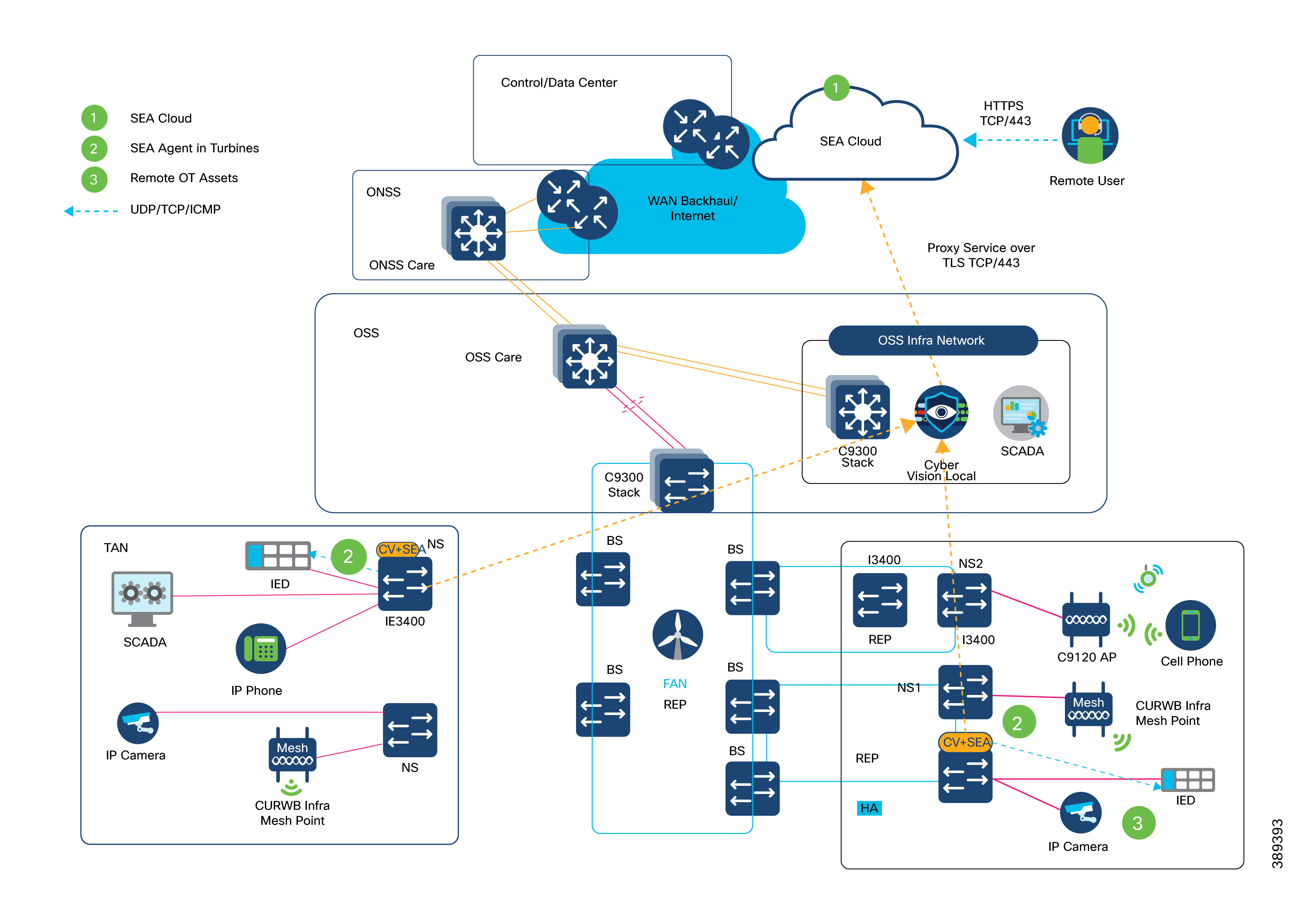
Design Requirements & Considerations
● Cisco CV Center in OSS infrastructure network must communicate with SEA Cloud Service with combined CV Sensor and SEA application deployed on turbine switches using active discovery method.
● SEA Agent on turbine switches communicates with SEA Cloud service using CV Center as proxy (for Internet access to reach the cloud), as shown in Figure 66.
● OSS Core handles northbound routing to SEA Cloud service and OT VLANs remain isolated in turbine network. WAN backhaul must support remote session bandwidth.
● Remote users are authenticated with SEA cloud service using either local authentication or integration with wind farm operator’s existing SSO or MFA systems.
● CV Sensor’s collection network interface/VLAN can be used as SEA Agent’s northbound interface/VLAN in wind farm’s management network VRF; SEA agent’s southbound interfaces are configured in an existing or a new dedicated OT VLAN in OT VRF for remote access to OT assets. OT VLANs remain unrouted to/from Cloud connected VLANs.
● One SEA agent supports up to a maximum of 10 concurrent sessions of different access methods like HTTP/HTTPS, SSH, RDP etc., Hence, total numbers of remote access session with SEA in a wind farm network directly translates to no. of SEA agents deployed in wind turbine network multiplied by 10 (i.e. Total Sessions = No. of SEA Agents X 10).
This combined CV and SEA deployment in wind farm asset operator network provides a simpler architecture with clear north/south segmentation and reduces interdependencies for easier scaling of the deployment. For more details, see Cisco SEA.
A DMZ in a wind farm OSS network provides a layer of security for the internal network by terminating externally connected services from the internet and cloud at the DMZ and allowing only permitted services to reach the internal network nodes.
The DMZ design in the wind farm architecture is a dual firewall model: the DMZ is protected by firewalls with redundancy. The OSS DMZ firewall at the OSS DMZ or third-party network helps provide controlled access into OSS network. It also provides segmentation and separation between OSS zones. The DMZ design uses a single firewall (with redundancy) with a minimum of three network interfaces to separate the external network, internal network, and DMZ.
Traditional stateful firewalls with simple packet filtering capabilities efficiently block unwanted applications because most applications meet the port and protocol expectations. However, in today's environment, protection based on ports, protocols, or IP addresses is no longer reliable or workable. This fact led to the development of an identity-based security approach, which takes organizations a step beyond conventional security appliances that bind security to IP addresses.
NGFW technology offers application awareness that provides you with a deeper and more granular view of network traffic in your systems. The level of information detail that NGFW provides can help with both security and bandwidth control.
Cisco NGFW (Cisco Secure Firewall appliance) resides at the network edge to protect network traffic from the external network. In the wind farm design, a pair of Cisco Secure Firewall appliances (Cisco Secure Firewall 2140s) are deployed as active and standby units for high availability. The Cisco Secure Firewall units must be the same model with the same number and types of interfaces and must be running the same software release. In the software configuration, the two units must be in the same firewall mode (routed or transparent) and have the same network time protocol (NTP) configuration.
The two units communicate over a failover link to check each other's operational status. Failovers that are triggered by events such as the primary unit losing power, the primary unit physical interface link going down, or the primary unit physical interface link having a connection issue. During a stateful failover, the primary unit continually passes per-connection state information to the secondary unit. After a failover occurs, the same connection information is available at the new primary unit. Supported end-user applications (such as TCP/UDP connections and states, and SIP signaling sessions) are not required to reconnect to keep the same communication session.
For more information, see Cisco Secure Firewall Management Center Configuration Guide.
In a wind farm network, Cisco Secure Firewall at the control center, OSS, and ONSS network edges provide zone-based network access control and remote access VPN services for secure remote connectivity into the wind farm network.
Securing the wind farm perimeter ensures that all traffic entering or exiting onshore and offshore networks is controlled and inspected where required.
Validated design security control points include the following:
● DMZ at a data center
● Normal enterprise security model for incoming WAN connectivity
● Clustered firewalls for IDS and IPS
● DMZ at onshore substation
● Redundant firewalls for IDS and IPS
● Secure local perimeter for third-party network connections
● Monitoring traffic flows for known threats
● Blocking undesirable traffic
● DMZ at offshore substation
● Redundant firewalls for IDS and IPS
● Secure perimeter for third-party network connections
● Monitoring traffic flows for known threats
● NAT for third-party networks
● Blocking undesirable traffic
Figure 67 shows the Cisco Secure Firewall design with security zones in wind farms. Multiple Cisco Secure Firewalls in different places in the network are managed by a centralized management application called Cisco Secure Firewall Management Center, which is deployed in the control center.
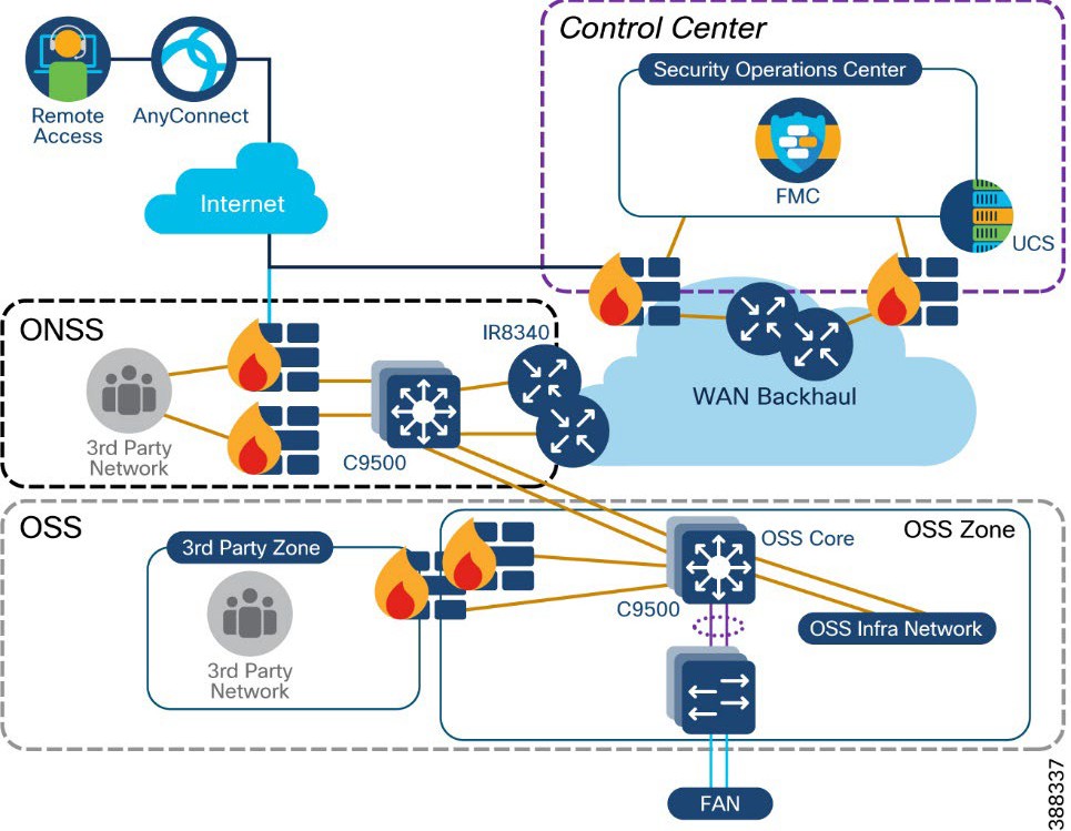 |
The following Cisco NGFW features are used in a wind farm network security:
● Standard firewall features includes traditional firewall functionalities such as stateful port and protocol inspection, network address translation (NAT), and virtual private network (VPN).
URL filtering:
● Set access control rules to filter traffic based on the URL that is used in an HTTP or HTTPS connection. Because HTTPS traffic is encrypted, consider setting SSL decryption policies to decrypt all HTTPS traffic that the NGFW intends to filter.
Application visibility and control (AVC):
● Discover network traffic with application-level insight with deep packet visibility into web traffic.
● Analyze and monitor application usages and anomalies.
● Build reporting for capacity planning and compliance.
● Next-generation intrusion prevention system (NGIPS):
● Collected and analyzed data includes information about applications, users, devices, operating systems, and vulnerabilities.
● Build network maps and host profiles to provide contextual information.
● Security automation correlates intrusion events with network vulnerabilities.
● Network weaknesses are analyzed and automatically generate recommended security policies to put in place to address vulnerabilities.
Advanced malware protection (AMP):
● Collects global threat intelligence feeds to strengthen defenses and protect against known and emerging threats.
● Uses that intelligence, coupled with known file signatures, to identify and block policy-violating file types, exploitation attempts, malicious files trying to infiltrate the network.
● Upon detection of threats, instantly alert security teams with an indication of the threat and detailed information about malware origin, system effects, and what the malware does.
● Update the global threat intelligence database with new information.
Table 17 lists the ports that must be allowed in a firewall to allow external third-party applications to access applications or services in the wind farm network.
Table 17. List of allowed Firewall Ports Facing Third-Party Networks
| Application |
Port Number |
References |
| IPSec tunnel |
UDP ports: 500 (ISAKMP), 4500 (NAT-T) ,1701 (L2TP), 10000 IP numbers: 50 (ESP), 51 |
|
| Remote access VPN |
TCP ports: 443,80 |
Cisco Secure Firewall Management Center Configuration Guide.
|
| Internet access (HTTP or HTTPS) |
TCP ports: 443,80 |
Security, Internet Access, and Communication
|
| SCADA OPC-UA (Turbine SCADA network to OSS infrastructure) |
TCP ports: 4840,4843, 4990 (See the reference document for various OPC-UA applications) |
“Unified Architecture Technology Sample Applications” on the OPC Foundation web site. |
Turbine Operator Network Security Design
This section discusses the turbine operator network security design in an offshore wind farm. Following two security approaches are explained in this section to secure the entire turbine operator network rings and its SCADA communication endpoints.
● MACsec Encryption between IE3400/IE3100, IE9320 and C9300 switches in the rings
● Private VLAN for micro-segmentation of SCADA endpoints connected to TSN and FSN
MACsec Encryption in Turbine Operator Network
MACsec is the IEEE 802.1AE standard for authenticating and encrypting packets between two MACsec-capable devices. Cisco switches support 802.1AE encryption with MACsec Key Agreement (MKA) on switch-to-host links for encryption between the switch and host device. The switch also supports MACsec encryption for switch-to-switch (inter-network device) security using MKA-based key exchange protocol. The MKA protocol provides the required session keys and manages the required encryption keys.
MACsec, defined in 802.1AE, provides MAC-layer encryption over wired networks by using out-of-band methods for encryption keying. The MACsec Key Agreement (MKA) Protocol provides the required session keys and manages the required encryption keys. MKA and MACsec are implemented after successful authentication using certificate-based MACsec or Pre-Shared Key (PSK) framework. When switch-to-switch MACsec is enabled, all traffic is encrypted except EAP-over-LAN (EAPOL) packets.
The MKA Protocol manages the encryption keys used by the underlying MACsec protocol. The basic requirements of MKA are defined in 802.1x-REV. The MKA Protocol extends 802.1x to allow peer discovery with confirmation of mutual authentication and sharing of MACsec secret keys to protect data exchanged by the peers.
In the turbine operator network, MACsec is enabled between each switch-to-switch link in the core REP ring, FSN and TSN rings, as shown in Figure 68.
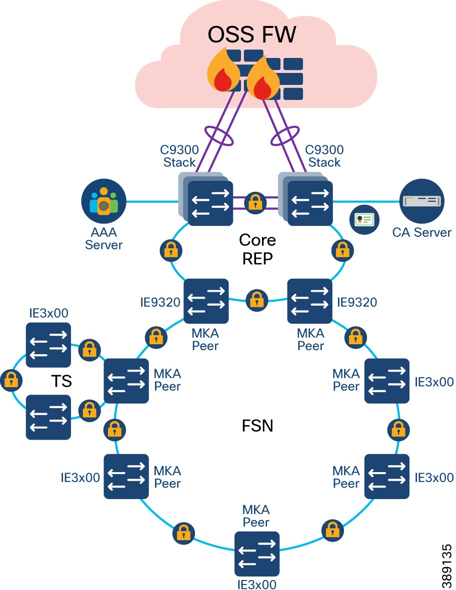 |
In Figure 69, MACsec MKA is supported on switch-to-switch links. Using certificate-based MACsec, you can configure MACsec MKA between device uplink ports. Certificate-based MACsec allows mutual authentication and obtains an MSK (master session key) from which the connectivity association key (CAK) is derived for MKA operations. Device certificates are carried, using certificate-based MACsec, for authentication to the AAA server. Device certificates are enrolled on the device for authentication either using Simple Certificate Enrollment Protocol (SCEP) or imported on the device manually.
Alternatively, you can also configure MACsec with Pre-Shared Key (PSK) between MACsec devices for authentication. However, it is recommended to configure turbine operator network with certificate based MACsec encryption for better security of the network.
MKA/MACsec can be configured on the port members of a port channel. MKA/MACsec is agnostic to the port channel since the MKA session is established between the port members of a port channel. It is recommended to configure the port channel link (between a TSN nacelle SCADA switch and a FSN base SCADA switch, as shown in Figure 70) within a turbine SCADA network with MKA/MACsec on all member ports for better security of the port channel.
Note: MACsec feature is not supported on Industrial Ethernet 3100 series switches. It is recommended to enable MACsec feature on rings of all IE3400 switches only.
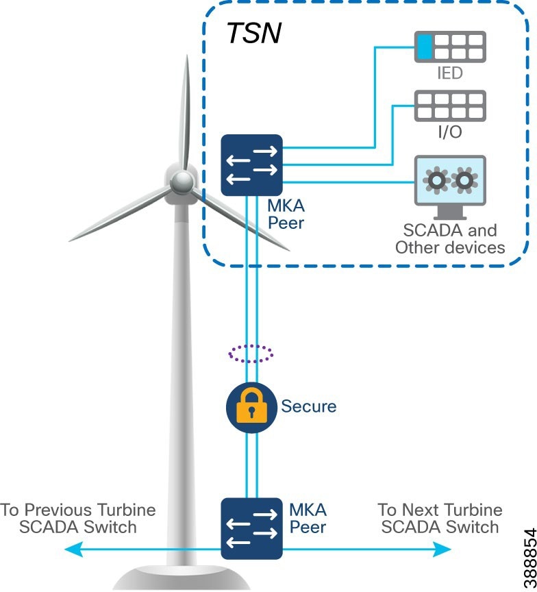 |
Note: IE3400 switches used in FSN and TSN rings also support host-to-switch MACsec encryption. When an IT/OT device supporting MACsec feature is connected to an IE3400 switch in the turbine operator network, device to switch communication can also be encrypted by leveraging host-to-switch MACsec feature.
Network micro-segmentation using Private VLAN
In offshore wind farms, turbine operator SCADA network is micro-segmented using Private VLANs to address the following challenges faces with VLANs:
● Scalability: The switch supports up to 1005 active VLANs. If the network administrator assigns one VLAN per customer, this limits the number of VLANs that the network can support.
● To enable IP routing, each VLAN is assigned a subnet address space or a block of addresses, which can waste the unused IP addresses and cause IP address management problems.
Using private VLANs addresses the scalability problem and provides IP address management benefits for network administrators and Layer 2 security for network users.
Private VLANs partition a regular VLAN domain into subdomains and can have multiple VLAN pairs—one for each subdomain. A subdomain is represented by a primary VLAN and a secondary VLAN. All VLAN pairs in a private VLAN share the same primary VLAN. The secondary VLAN ID differentiates one subdomain from another.
There are two types of secondary VLANs:
● Isolated VLANs—Ports within an isolated VLAN cannot communicate with each other at the Layer 2 level.
● Community VLANs—Ports within a community VLAN can communicate with each other but cannot communicate with ports in other communities at the Layer 2 level.
Private VLANs provide Layer 2 isolation between ports within the same private VLAN. Private-VLAN ports are access ports that are one of these types:
● Promiscuous—A promiscuous port belongs to the primary VLAN and can communicate with all interfaces, including the community and isolated host ports that belong to the secondary VLANs associated with the primary VLAN.
● Isolated—An isolated port is a host port that belongs to an isolated secondary VLAN. It has complete Layer 2 separation from other ports within the same private VLAN, except for the promiscuous ports. Private VLANs block all traffic to isolated ports except traffic from promiscuous ports. Traffic received from an isolated port is forwarded only to promiscuous ports.
● Community—A community port is a host port that belongs to a community secondary VLAN. Community ports communicate with other ports in the same community VLAN and with promiscuous ports. These interfaces are isolated at Layer 2 from all other interfaces in other communities and from isolated ports within their private VLAN.
Figure 70 shows Private VLAN design in the wind farms turbine operator SCADA network for segmenting the traffic in the network for security and as well address VLAN scalability concerns.
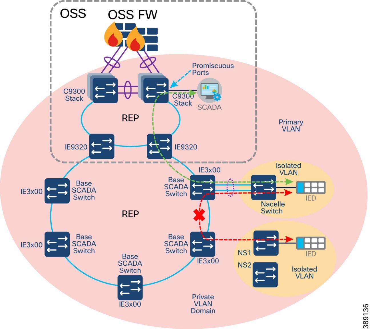 |
In Figure 70:
● A private VLAN (PVLAN) domain is configured with more than one isolated VLANs configured across core REP, FSN and TSN REP rings.
● Turbine operator SCADA devices like IEDs, PLCs, Switchgears, Sensor are assigned in a separate isolated VLANs, so that these devices cannot communicate with each other in the same PVLAN domain.
● However, the devices in isolated VLANs can communicate to its Primary VLAN and a SCADA server connected to a Promiscuous port in the core network.
● This design also ensures a greater number of private VLAN and isolated VLAN pairs can be configured in the network depending on the segmentation and scalability needed in the network for various endpoints connected to it.
Figure 71 shows Private VLAN design within the Turbine SCADA Network (TSN) and across trunks between the turbines for segmenting various SCADA traffic from devices like IEDs, transformers, switchgear, etc.
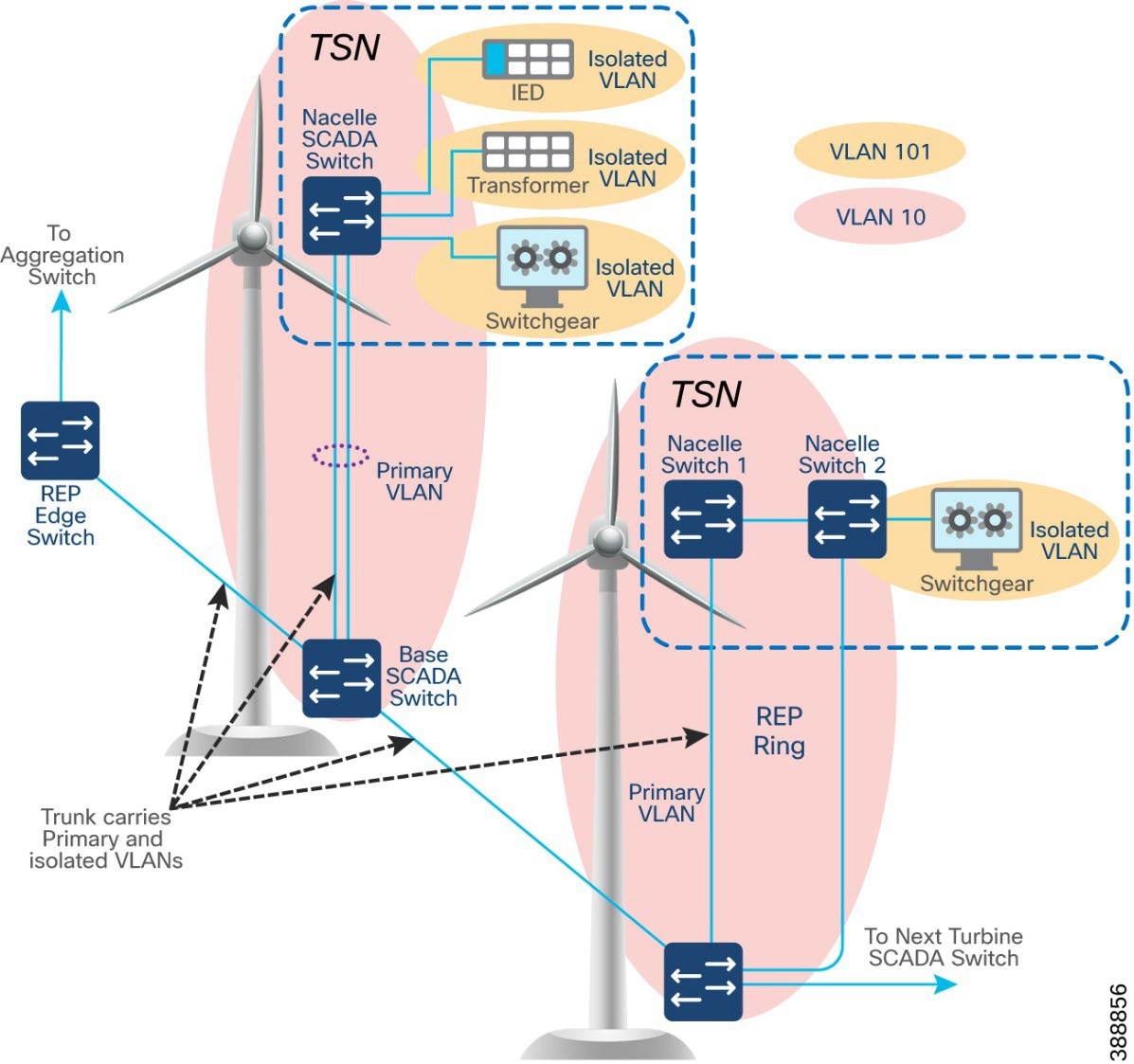 |
In Figure 71:
● Private VLAN (for example, VLAN 10) segregates turbine devices from other turbine SCADA devices
● One Primary VLAN (for example, VLAN 10) and one isolated VLAN (for example, VLAN 101) spanning across trunk ports of multiple switches in FSN and TSN rings
● Devices in same isolated VLAN cannot communicate with each other
● Isolated port communicates only to promiscuous ports of primary VLAN. SCADA device is isolated port communicates to a server which is generally connected in the OSS core network C9300 switch via a promiscuous port configuration
Refer to the following URLs for more details on Private VLAN feature in Cisco Catalyst 9300 Series Industrial Ethernet switches:
Alternatively, IE3400 switches support Cisco TrustSec (CTS) feature for micro-segmentation of the network. IE3400 switches in TSN and FSN rings having Network Advantage licenses can do Scalable Group Tag (SGT) based inline tagging and enforcing SGACL based security policies for device-to-device communication within a VLAN.
Cisco TrustSec (CTS) architecture consists of authentication, authorization and services modules like guest access, device profiling etc., TrustSec is an umbrella term, and it covers anything to do with endpoint’s identity, in terms of IEEE 802.1X (dot1x), profiling technologies, guest services, Scalable Group based Access (SGA) and MACSec (802.1AE). CTS simplifies the provisioning and management of secure access to network services and applications.
For more details on Cisco TrustSec feature, refer to the follow URL:
https://www.cisco.com/c/en/us/solutions/enterprise-networks/trustsec/design-guide-listing.html
NERC CIP Compliance Features and Guidance
The North American Electric Reliability Corporation (NERC) Critical Infrastructure Protection (CIP) standards are a set of requirements designed to secure the Bulk Electric System (BES) in North America. The CIP Cyber Security Standards use the “BES Cyber System” to apply requirements to groups of devices rather than individual Cyber Assets, as malware protection applies to the system as a whole and may not be necessary for every individual device to comply.
It is up to the Responsible Entity (any organization that operates elements of the BES) to determine the level of granularity at which to identify a BES Cyber System. For example, the Responsible Entity might choose to view an entire turbine operator control system as a single BES Cyber System, or it might choose to view certain components of the turbine operator control system as distinct BES Cyber Systems.
The scope of the CIP Cyber Security Standards is restricted to BES Cyber Systems that would impact the reliability of the BES, otherwise known as the impact rating. Each BES Cyber System can be categorized as High, Medium, Low or non-BES. The impact rating criteria can be found in CIP-002-5.1a, attachment 1.
Understanding the impact rating of your BES Cyber System is an important first step for NERC CIP compliance, as the outcome of this step will determine the pertinency of the proceeding standards. CIP-003-9 mandates responsible entities to specify consistent and sustainable security management controls to protect BES Cyber Systems against compromise that could lead to mis-operation or instability in the BES. For high impact and medium impact BES Cyber Systems, responsible entities must address the following topics:
● Personnel and training (CIP-004)
● Electronic Security Perimeters (CIP-005) including interactive Remote Access
● Physical security of BES Cyber Systems (CIP-006)
● System security management (CIP-007)
● Incident reporting and response planning (CIP-008)
● Recovery plans for BES Cyber Systems (CIP-009)
● Configuration change management and vulnerability assessments (CIP-010)
● Information protection (CIP-011)
● Declaring and responding to CIP Exceptional Circumstances
For low impact BES Cyber Systems, responsible entities must address the following topics:
● Cyber security awareness
● Physical security controls
● Electronic access controls
● Cyber Security Incident response
● Transient Cyber Assets and Removeable Media malicious code risk mitigation
● Vendor electronic remote access security controls
● Declaring and responding to CIP Exceptional Circumstances
Cisco’s support for key NERC CIP security requirements across High and Medium impact BES Cyber Systems are outlined below.
CIP-005-7 - Electronic Security Perimeter(s)
The purpose of this requirement is to manage electronic access to BES Cyber Systems by specifying a controlled Electronic Security Perimeter (ESP) in support of protecting BES Cyber Systems against compromise. All applicable Cyber Assets connected to a network via a routable protocol must reside within a defined ESP.
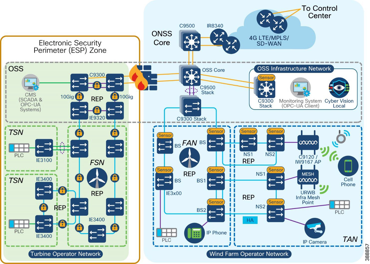 |
Cisco Secure Firewall can be used as the identified electronic access point (EAP) for NERC CIP compliance. Using the application rules hosted on the firewall, operators can deny access by default, and grant specific application access to only the devices that require it, including limiting operations to read only capabilities, if using protocols such as DNP3 to gather information from the control systems.
Cisco Secure Firewall also runs the Snort intrusion detection / prevention system (IDS/IPS) that is used to detect known or suspected malicious communication both inbound and outbound the operator network.
Additionally, CIP-005-7 calls for cybersecurity measures on remote access management.
Cisco Secure Equipment Access (SEA) is a hybrid cloud model for implementing Zero Trust Network Access (ZTNA) to operational networks. Operators can deploy SEA agents outside of the ESP which act as the intermediary system for remote access attempts. As per requirements, administrators of the platform can force all users to undergo Multi-Factor Authentication (MFA), and to monitor, record and terminate (if needed) all active sessions.
CIP-007-6 – System Security Management
The purpose of this requirement is to define methods, processes, and procedures for securing assets within the ESP. The Cisco Secure Firewall, which can be managed centrally by Cisco Secure Firewall Management Center or locally with Cisco Secure Firewall Device Manager, enables security administrators to enable only the communication channels that have deemed to be necessary for operations. To mitigate the threat of malware, Cisco Secure Firewalls can be deployed with a set of IPS signatures that recognise these signatures and patterns, with new signatures being pushed by FMC when new packages are made available.
If events do trigger, such as cyber assets attempting to use blocked ports, or malware signatures being matched, all logs will be collected centrally at the FMC. This allows administrators to deploy their firewalls to multiple parts of the network but maintain a single dashboard for viewing the health of the network.
NERC CIP also calls for security to be extended beyond the firewall, and when using Cisco switching infrastructure, protection against the use of unnecessary physical ports can be put in place. When deploying a large switching infrastructure, it is recommended to use Cisco Catalyst Center so policies can be managed centrally. Catalyst Center also becomes the home for security event monitoring on the switches, and can push software patches to the network infrastructure quickly if a vulnerability in the software was to be found. If desired, network port ranges could also be locked down via IP Access Control Lists (ACLs) or Security Group ACLs with Cisco Identity Services Engine.
CIP-008-6 – Incident Reporting and Response Planning
The purpose of this requirement is to mitigate the risk to the reliable operation of the BES as the result of a Cyber Security incident. The detection of an incident can occur in many part of the architecture, such as security events across the firewall, rogue devices connecting to a switch, or Cisco Cyber Vision seeing new communication in a baseline. Incident investigation typically starts with one event, but it is only when multiple sources of information have been correlated together do we get the complete picture. Cisco Extended Detection and Response (XDR) is a security platform that integrates with Cisco and third-party tools to detect and respond to complex threats. For example, if Cyber Vision is to detect a potential indicator of compromise, the event can be promoted to Cisco XDR where additional context can be observed. If additional context leads a security admin to believe a real threat has occurred, XDR workflows can be triggered to initiate a response action.
If Cisco XDR is not the response tool of choice, Cisco build their products with an API-first strategy, where any third-party software can interact with Cisco technology for both data gathering and response actions.
CIP-010-4 – Configuration Change Management and Vulnerability Assessments
The purpose of this requirement is to prevent and detect unauthorized changed to BES Cyber Systems by specifying change management and vulnerability assessment requirement. When using Cisco Catalyst Center to deploy Cisco Industrial Ethernet Switches, templates are created for provisioning the device.
Baselining however also applies to the Cyber Assets, not just the network infrastructure. Cisco Cyber Vision, which will be used to document the vulnerabilities of the assets, can also be used to monitor a baseline for the network. Any new asset introduced to the network, or any deviations from known communication pattern will be captured, and this new information can either be added to the baseline as an accepted deviation or flagged for investigation.
CIP-011-3 – Information Protection
The purpose of this requirement is to prevent unauthorized access to BES Cyber System information. Not only is all access to Cisco technology protected by user access control, network security policies, such as those deployed in the Cisco Secure Firewall, will ensure that unauthorized users cannot gain access to the systems.
CIP-013-2 – Supply Chain Risk Management
The purpose of this requirement is to implement security controls for supply chain risk management of BES Cyber Systems. Cisco's Security and Trust Organization defines our secure development lifecycle (Cisco SDL), creates and maintains common security libraries, and manages our PSIRT process and privacy activities across all Cisco product lines.
Engineering teams must comply with the Cisco SDL which is certified for compliance with IEC62443-4-1. This certification underscores that we maintain a security culture and that our products can be trusted. Some Cisco products also have IEC 62443-4-2 certifications.
The Cisco SDL process ensures security and trustworthiness are designed, built, and delivered from the ground up. Trustworthy technologies such as image signing, secure boot, Cisco Trust Anchor module, and runtime defenses help ensure that the code is authentic, unmodified, and operating as intended. A hardware-level root of trust, unique device identity, and validation of all levels of software during startup establish a chain of trust in the system.
The Cisco Product Security Incident Response Team (PSIRT) receives, investigates and publicly reports security vulnerability information related to Cisco products. All product PSIRTs result in the delivery of both patches AND protection and mitigation advice for the period before patches can be applied.
Cisco is also an active contributor to industrial IoT relevant standard work, defining Manufacturer Usage Description (RFC 8520), participating in security standards work for ODVA (CIP/EIP), IEC 62443, IEC 61850, NIST SBOM definitions, et al.
Network Scale and High Availability Summary
Failure of any part of the network (either a network device or a network link) can affect the availability of services. The effect of availability increases with the increase in the aggregation level of the failing node or link. Availability is improved by avoiding a single point of failure by means of high availability (HA) or redundancy. Therefore, every critical component and link in the overall network should have HA or redundancy designed in and configured.
This chapter discusses scale, HA, and redundancy considerations for the entire solution, and includes the following topics:
● Network High Availability Summary
A large offshore wind farm with multiple locations can have from 50 to 300 turbines. We recommend that a maximum FAN ring size of no more than 18 switches be configured because Catalyst Center automated REP workflow provisioning can support up to a maximum of 18 switches in a REP ring. Form multiple FAN rings of IE3400 turbine base switches when the number of turbines exceeds 18.
Cisco Catalyst 9300 series switches serve as FAN ring aggregation switches. Each switch can have up to 48 ports, and 8 switches can be stacked together to provide scale and redundancy. Each REP ring uses two ports on a 9300 for termination. With a minimum of 2 switches in a stack, up to 24 concurrent rings are supported. Each FAN ring can support a maximum of 18 Cisco Industrial Ethernet switches. For further expansion, either additional switches can be added to the stack or additional switch stacks can be created with Cisco Catalyst 9300 series switches.
We recommend aggregating no more than 10 FAN rings on a stack of dual Catalyst 9300 switches for optimal network performance. If the number of turbines or base switches is greater than 180 (10 FAN rings of 18 nodes each), another stack of dual Catalyst 9300 switches should be added to FAN aggregation network.
Thus, the wind farm FAN ring, FAN aggregation, and OSS and ONSS core systems can be scaled from a small deployment to a large deployment in terms of the number of endpoints connected, bandwidth requirements, and area to be covered.
The scale numbers are summarized below:
● Maximum number of access ports per nacelle or base (IE switch): 26 (IE 3x00)
● Maximum number of nodes per ring: 18
● Maximum bandwidth of a FAN ring: 1 Gbps
● Maximum number of concurrent FAN rings per FAN aggregation stack (one pair of 9300): 10
● Maximum number Cisco Catalyst 9300 switches in a stack: 8 (we recommend configuring a stack of 2 switches)
● Maximum number of Cisco Catalyst 9500 switches in a StackWise Virtual: 2
Wind Farm Operator Network High Availability Summary
For information about the high availability design for TANs, see TAN High Availability Design with REP.
FAN ring connectivity is provided with Cisco Industrial Ethernet (IE) switches and an REP ring. REP rings provide redundancy for the uplinks of the base switches in a FAN ring. A REP ring network converges within 100 ms and provides an alternate path if a link failure occurs.
For more information about the FAN high availability design, see FAN REP Ring Design.
FAN Aggregation High Availability
High availability is provided at the FAN aggregation layer for the Cisco Catalyst 9300 by configuring Cisco StackWise-
480. Cisco StackWise-480 is an advanced Cisco technology with support for son-stop forwarding with stateful switchover (NSF/SSO) for the most resilient architecture in a stackable (sub-50 ms) solution. For more information, see Cisco Catalyst 9300 Series Switches Data Sheet.
OSS and ONSS Core High Availability
A Cisco Catalyst 9500 at an OSS and ONSS core network differs from the Catalyst 9300 (StackWise 480) insofar as the 9300 has physical backplane stacking cables, with a maximum distance of 30 ft (10 m) between switches in a stack, whereas the Catalyst 9500 (StackWise Virtual) uses Ethernet interfaces and can be split across much greater distances.
The StackWise Virtual Link (SVL) is typically made up of multiple 10 or 40 Gbps interfaces, associated transceivers (for example, SFP+/QSFP), and cabling. These items are dedicated to the SVL and provide a virtual backplane between the two physical Catalyst 9500 switches. They cannot be used for any other purpose. In a wind farm, we recommend having two physical SVL links, and one dual-active detection (DAD) link.
For more information about SVL, see High Availability Configuration Guide, Cisco IOS XE Dublin 17.10.x (Catalyst 9500 Switches).
For information about Cisco C9800 WLC high availability configuration, see High Availability SSO Deployment Guide for Cisco Catalyst 9800 Series Wireless Controllers, Cisco IOS XE Amsterdam 17.1
C9800 WLC HA can also be configured using the prebuilt DNA-C workflow. Sample configuration and steps are provided in Cisco Wind Farm Solution Implementation Guide.
For information about MeshEnd redundancy deployment. See URWB Wireless Backhaul.
Redundancy should be configured for various critical servers in the network, such as Cisco Catalyst Center, ISE, FND, DHCP, DNAC, and CA. The Cisco Catalyst Center supports inherent redundancy within cluster.
Cisco Catalyst Center Redundancy
Cisco Catalyst Center redundancy is provided by clustering three Cisco Catalyst Center appliances together. Clustering provides for sharing of resources and features and helps enable high availability and scalability. The Cisco Catalyst Center supports single-host or three-hosts cluster configurations.
The three-hosts cluster provides both software and hardware high availability. The three-nodes cluster can inherently do service and load distribution, database replication, and security replication. This cluster survives the loss of a single node.
The single host cluster does not provide hardware high availability. Therefore, we recommend using a three hosts cluster for wind farm Cisco Catalyst Center high availability deployments. For more detailed information, see Catalyst Center High Availability Guide.
If the Cisco Catalyst Center appliance becomes unavailable, the network still functions, but automated provisioning and network monitoring capabilities are not possible until the appliance or cluster is repaired or restored.
Cisco ISE has a highly available and scalable architecture that supports standalone and distributed deployments. In a distributed environment, you configure one primary administration ISE node to manage the secondary ISE nodes that are deployed in the network. For more detailed information, see Cisco Identity Services Engine Administrator Guide.
Configuring high availability, also called failover, requires two identical Cisco Secure Firewall Threat Defense devices connected to each other through a dedicated failover link and, optionally, a state link. Cisco Secure Firewall Threat Defense supports active and standby failover, where one unit is the active unit and passes traffic. The standby unit does not actively pass traffic but synchronizes configuration and other state information from the active unit. When a failover occurs, the active unit fails over to the standby unit, which then becomes active.
For more detailed information, see Cisco Secure Firewall Management Center Device Configuration Guide.
Cisco SD-WAN redundancy is achieved in different ways, depending on the SD-WAN components. We recommend the cloud-hosted deployment for Cisco SD-WAN controllers, which provides an easy way to deploy and scale with high availability.
Cisco SD-WAN Validator SD-WAN Validator Orchestrator
Cisco SD-WAN Validator orchestrator redundancy is achieved by spinning up multiple Cisco SD-WAN Validator controllers and using a single fully qualified domain name (FQDN) to reference the Cisco SD-WAN Validator controllers. To maintain proper redundancy, we recommended using Cisco SD-WAN Validator orchestrators in different geographic regions if they are managed from the cloud, or in different geographic locations or data centers if they are deployed on premises. This approach ensures that at least one Cisco SD-WAN Validator controller is always available when a Cisco SD-WAN managed device attempts to join the network.
Cisco SD-WAN SD-WAN Controller
For Cisco SD-WAN controllers, redundancy is achieved by adding additional controllers which act in an active/active fashion. To maintain proper redundancy, we recommend using Cisco SD-WAN controllers in different geographic regions if they are managed from the cloud, or in different geographic locations or data centers if they are deployed on premises.
Cisco SD-WAN Manager SD-WAN Manager Clustering
A Cisco SD-WAN Manager cluster can distribute various NMS service loads and provide high availability and scalability for the Cisco SD-WAN Manager services. A Cisco SD-WAN Manager cluster consists of at least three Cisco SD-WAN Manager server instances, with each instance active and running independently. Control connections between the Cisco SD-WAN Manager servers and WAN routers are load balanced. Control connections (from each Cisco SD-WAN Manager instance to each Cisco vSmartSD-WAN controller from each Cisco SD-WAN Manager instance to each other Cisco SD-WAN Manager instance, and from each Cisco SD-WAN Manager instance core to each Cisco SD-WAN Validator orchestrator) are fully meshed. For more detailed information about Cisco SD-WAN high availability design, see Cisco Secure Firewall Management Center Device Configuration Guide.
Turbine operator Network High Availability Summary
SCADA Core Network High Availability
Turbine operator SCADA core network high availability design is provided through core REP configuration between Catalyst 9300 Series core switches stack and Industrial Ethernet 9320 switches as FSN aggregation switches in the core ring. Also, the HSRP design in C9300 core switches stack between two cabinets provide first-hop gateway redundancy for all VLANs in the turbine operator network.
For more information about the Core network high availability design, see OSS (third-party) Turbine Operator Core Network Ring Design.
FSN ring connectivity is provided with Cisco Industrial Ethernet (IE) switches and an REP ring. REP rings provide redundancy for the uplinks of the base SCADA switches in a FSN ring. A REP ring network converges within 100 ms and provides an alternate path if a link failure occurs.
For more information about the FSN high availability design, see Farm area SCADA Network (FSN) Design.
For information about the high availability design for TSNs, see TSN High Availability Design with REP.
Turbine Operator Compact Onshore Substation
A turbine operator may have their own onshore substation with SCADA applications or controllers for the smaller number of turbines and SCADA devices connected to them in a wind farm. This chapter discusses the design of a compact onshore substation for a turbine operator in a Wind Farm. This turbine operator compact onshore substation network design is independent of turbine operator’s full-fledged network design with offshore substation (OSS) discussed in the section “Turbine Operator Network design”.
This chapter includes the following topics:
● Compact Onshore Substation Use Cases
● Compact Onshore Substation Network Architecture
● Compact Onshore Substation Network Security
● Compact Onshore Substation Network QoS and Visibility
Compact Onshore Substation Use Cases
Table 18 lists the key use cases in a turbine operator compact onshore substation.
Table 18. Compact Onshore Substation Use Cases
| Use Case |
Type of Services |
Description |
| WTG SCADA |
Turbine telemetry Fire detection Turbine ancillary systems |
Telemetry data collection associated with turbine systems and components Detection of smoke and fire within the turbine |
| SCADA Services |
Turbine operational telemetry data collection Turbine telemetry data (SCADA) translation to OPC-UA Provide turbine monitor and operational data to Utility DMZ network using OPC-UA |
Turbine monitor and operational data collection using SCADA systems OPC-UA gateway/server which translates turbine telemetry data (Ex. SCADA MODBUS) into OPC-UA protocol messages Provide turbine telemetry data as OPC-UA protocol messages to utility DMZ network on demand |
Table 19 lists the traffic types and flows in a turbine operator compact onshore substation.
Table 19. Compact Onshore Substation Traffic Types and Flows
| Traffic Type |
Traffic Flows in the Network |
| SCADA data for monitoring and control |
Turbine base switch or nacelle to SCADA Controller: PLC in turbine base or nacelle switch to a SCADA controller in ONSS core network using SCADA protocols (for example: DNP3, MODBUS, or T104) |
| Encrypted SCADA data traffic to Data Center |
IPSec encrypted SCADA data from a SCADA controller in Compact substation inside/core network to SCADA server in the Data Center or headend via FlexVPN tunnel |
| SCADA OPC-UA and application protocol traffic |
SCADA OPC-UA protocol traffic between Utility DMZ and ONSS inside network SCADA OT Protocols (DNP3/MODBUS IP) to OPC-UA protocol messages translation (OPC-UA gateway) between IED, Switchgear and OPC-UA server/SCADA Controller in ONSS inside core network FTP application or TCP traffic from inside core network to Utility DMZ network |
Compact Onshore Substation Network Architecture
Turbine operator’s compact substation network architecture is built on the following functional blocks:
● Turbine operator data center (includes data center applications and headend router): Hosts turbine operator’s OT data center applications and servers such as FTP server, SCADA Server, CA Server etc. and a headend router (HER) for remote onshore substation connectivity
● Wind farm wide area network (WAN): A backhaul network for interconnecting a remote compact onshore substation with a control center. It can be a public service provider Ethernet WAN or LTE network backhaul
● Onshore substation WAN Edge: A remote site WAN edge router in a wind farm that interconnects an onshore substation with a control center via a WAN over FlexVPN
● Onshore Substation Core: Consists of onshore core network switch to provide network connectivity and application access to wind turbine bases and nacelle switches and their SCADA endpoints; core switch also aggregates Farm area SCADA network rings
● Farm area SCADA network (FSN): An aggregation network that connects multiple wind turbines base switches and to their collapsed core and aggregation switch
● Turbine area SCADA network (TSN): A switched layer 2 network typically formed by one or more nacelle switches in a wind turbine.
Figure 73 shows the end-to-end compact onshore substation network architecture of a wind farm turbine operator.
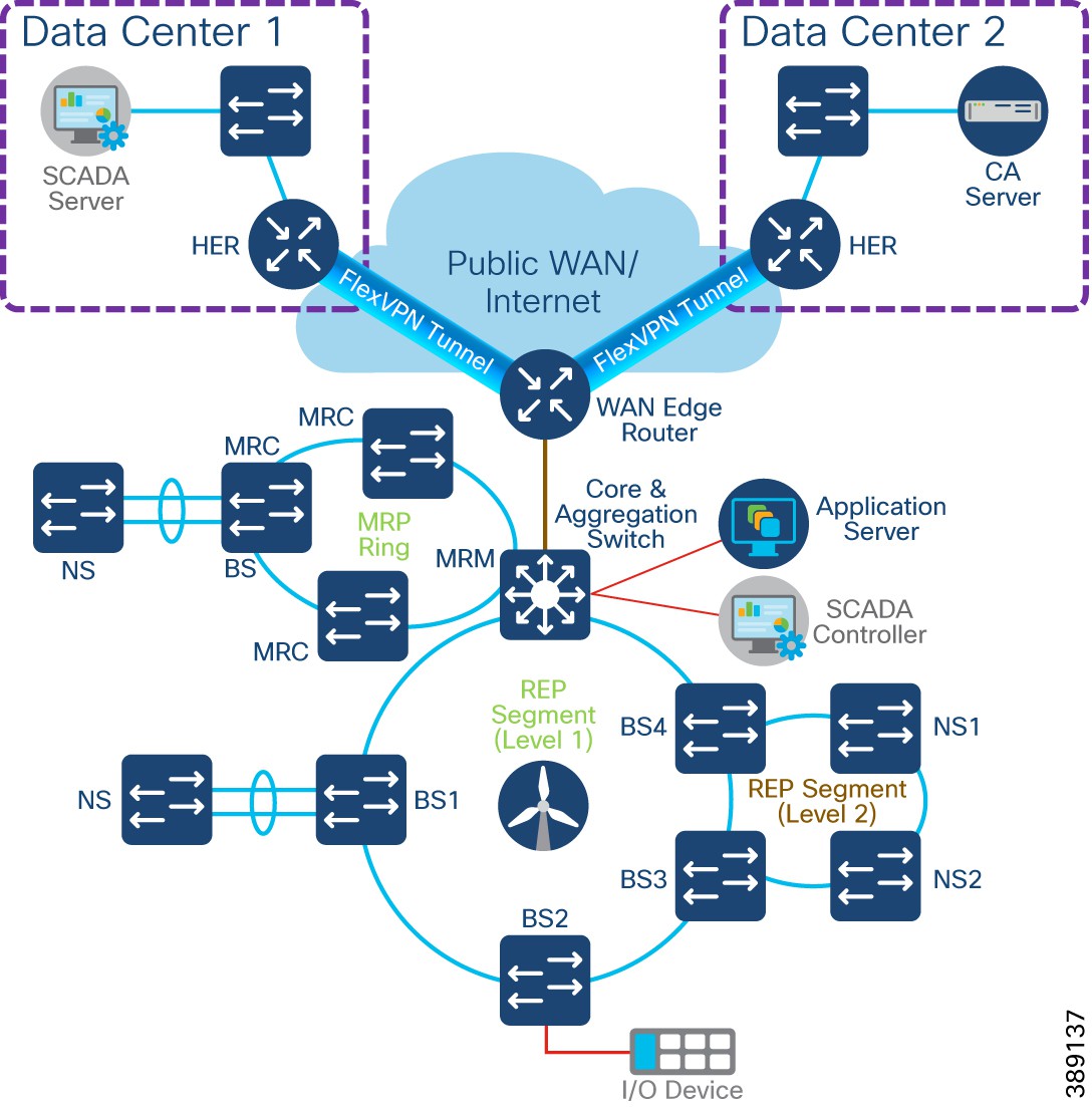 |
Core Network and Routing design considerations
A compact substation core network is composed of a Cisco Industrial Ethernet 3500 Series switch as layer 3 devices that provide core network, FSN rings aggregation and routing capabilities.
The core switch connects to multiple components. The OSS core network connects the following components in a compact substation network, as shown in Figure 73.
● WAN Edge Router: Cisco Catalyst IR1101 Rugged Series router that connects core network to one or more data centers
● FSN aggregation: Aggregates FSN rings (REP and MRP) in a compact substation
● Application Servers: provide network connectivity and application access to wind turbine bases and nacelle switches and their SCADA endpoints
● Layer 3 boundary on core switch with OSPF routing protocol: Routes all compact substation inside networks that require access to data center applications via WAN edge router. Also acts as a default gateway for all substation local subnets
WAN Edge with FlexVPN network design
Cisco IR1101 as WAN Edge Router
Cisco Catalyst IR1101 Rugged Series Router is a modular and ruggedized platform designed for remote asset management across multiple industrial vertical markets. In a compact onshore substation, the IR1101 can plan the role of substation WAN edge router that provide offshore wind farm SCADA controllers and devices access to a remote data center application services via WAN.
IR1101 is designed as a modular platform for supporting expansion modules with edge compute. IR1101 supports a variety of communication interfaces such as four FE ports, one combo WAN port, RS232 Serial port, and LTE modules. The cellular module is pluggable and a dual SIM card and IPv6 LTE data connection are supported.
SCADA Raw sockets and protocol translation features are available. For more details see Cisco Catalyst IR1101 Rugged Series Router Data Sheet.
Cisco Catalyst 8300 Series Edge Platform as HER
Cisco Catalyst 8300 Series Edge Platforms (Catalyst 8300) with Cisco IOS XE SD-WAN Software deliver Cisco’s secure, cloud-scale Catalyst SD-WAN solution for the branch. The Catalyst 8300 Series is purpose-built for high performance and integrated SD-WAN Services along with flexibility to deliver security and networking services together from the cloud or on premises.
The Catalyst 8300 Series Edge Platforms have a wide variety of interface options to choose from—ranging from lower and higher module density with backward compatibility to a variety of existing WAN, LAN, voice, and compute modules. The Catalyst 8300 Series Edge Platforms are well suited for medium-sized and large sized data center branch offices for high WAN IPSec performance with integrated Cisco Catalyst SD-WAN services.
For more details see Cisco Catalyst 8300 Series Edge Platforms Data Sheet.
Since turbine operator SCADA traffic can traverse any kind of public WAN, data should be encrypted with standards-based IPSec. This approach is advisable even if the WAN backhaul is a private network. An IPSec VPN can be built between the WAN edge router (IR1101) and a headend router in the data center. The compact substation implements a sophisticated key generation and exchange mechanism for both link-layer and network-layer encryption.
IP tunnels are a key capability for all remote site use cases forwarding various traffic types over the backhaul WAN infrastructure. Various tunnelling techniques may be used, but it is important to evaluate the individual technique OS support, performance, and scalability for the WAN edge (IR1101) and HER platforms.
The following is tunnelling design guidance:
● FlexVPN Tunnel— FlexVPN is a flexible and scalable VPN solution based on IPSec and IKEv2. To secure data communication with the headend across the WAN, FlexVPN is used. IKEv2 prefix injection is used to share tunnel source loopbacks.
● Routing of compact substation inside network or local subnet prefixes to data center headend network via WAN can be done using internal Border Gateway routing Protocol (iBGP)
● A compact substation WAN edge router (IR1101 as a spoke router) establishes a FlexVPN tunnel with each HER (Hub router), in more than one data center connectivity for data/control center application services high availability
● An IP routing protocol must be configured between WAN edge IR1101 and HER to exchange routing tables between DC headend and IR1101. Internal Border Gateway Protocol (iBGP) is recommended to simplify and ease the IP routing table advertisements across WAN.
● LAN subnets or VLANs in compact substation inside network can be redistributed or advertised to HER the routing protocol (iBGP).
Farm Area SCADA Network (FSN) REP Ring Design
In turbine operator compact substation network, the IE3400 and/or IE3100 Series switches as the base SCADA switch from each wind turbine is connected in a closed ring topology using a 1G fiber cable with Cisco Industrial Ethernet 3500 switch to form a farm area SCADA network (FSN) ring. A REP is configured in the FSN ring to provide FAN resiliency for faster network convergence if a REP segment fails.
Figure 74 shows a FSN ring aggregating to a Cisco IE switch in the core REP segment.
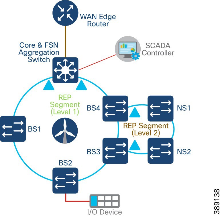 |
● Cisco Industrial Ethernet 3400 and/or 3100 series switches are used as turbine base SCADA network switches in the design
● A layer 2 closed ring of turbine base SCADA switches connected via 1G fiber forms a Farm area SCADA Network (FSN) ring for turbine operators
● One Gigabit Ethernet closed ring of up to 10 switches in a ring is recommended for a compact substation
● IE3500 core switch in the REP ring aggregates up to four FSN rings with each ring having a maximum of up to 10 base IE3400 switches; It is recommended to aggregate up to 4 FSN REP rings only on IE3500 (with additional fiber ports expansion modules in it) for optimal network performance
● REP is configured for base SCADA switches/FSN resiliency such that REP edge ports are on the core switch
● FSN base switches aggregate another subtended REP ring traffic from turbine nacelle SCADA switches with HA deployment
● Multiple VLANs are configured for network segmentation of FSN devices. Examples include VLAN for SCADA endpoints, management VLAN (FTP and SSH) etc.
FSN with MRP and REP Rings Design
A turbine operator could also be having a farm area SCADA network (FSN) ring of turbine base switches configured with a standard based Media Redundancy Protocol (MRP) for network resiliency. Cisco IE core switch in the compact substation can also connect only MRP ring of FSN or MRP ring(s) coexisting with REP ring(s) of turbine base switches. This section discusses both MRP only ring and MRP and REP ring coexistence design options in FSN.
Media Redundancy Protocol (MRP), defined in International Electrotechnical Commission (IEC) standard 62439-2, provides fast convergence in a ring network topology for industrial networks. Media Redundancy Manager (MRM) defines its maximum recovery times for a ring in the following range: 10 ms, 30 ms, 200 ms and 500 ms. However, the default maximum recovery time on Cisco IE switch is 200ms for a ring composed of up to 50 node.
In an MRP ring, the MRM serves as the ring manager, while the Media Redundancy Clients (MRCs) act as member nodes of the ring. Each node (MRM or MRC) has a pair of ports to participate in the ring. The core switch in the compact substation is configured as MRM and each turbines base IE3400 switch is configured as MRC. MRP default profile of 200ms ring convergence is configured. It is recommended to aggregate up to a maximum of three MRP rings to the core switch for optimal network performance of FSN.
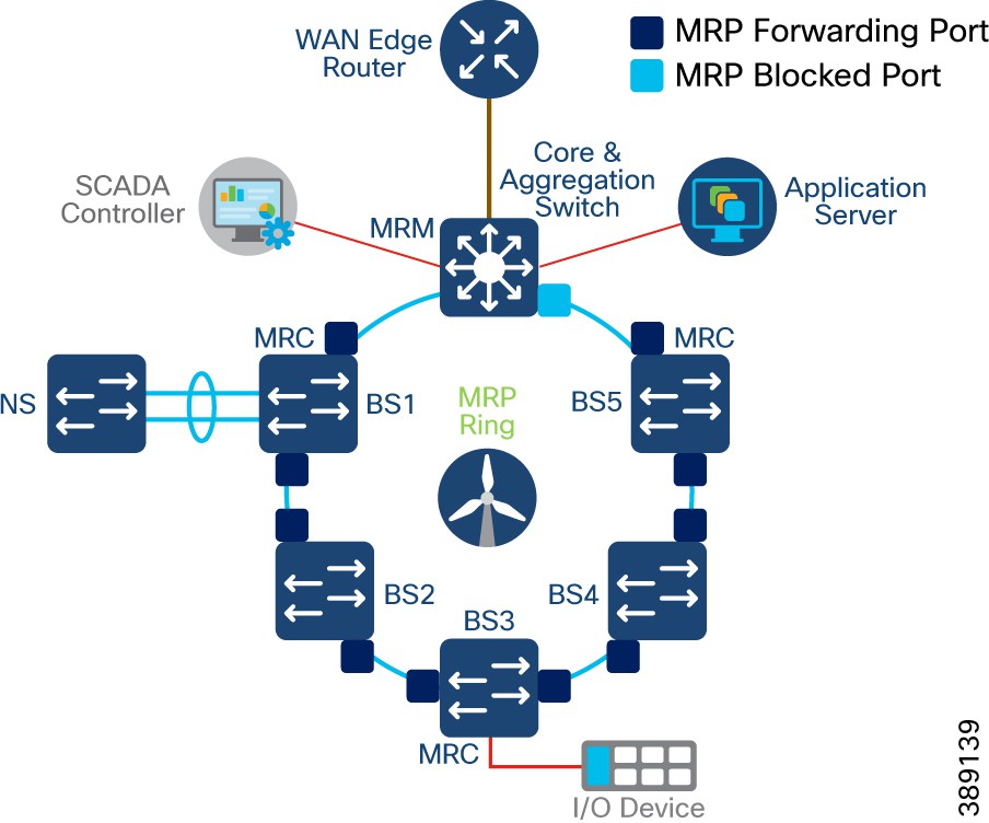 |
The MRM initiates and controls the ring topology to react to network faults by sending control frames on one ring port over the ring and receiving them from the ring over its other ring port, and conversely in the other direction. An MRC reacts to received reconfiguration frames from the MRM and can detect and signal link changes on its ring ports.
During normal operation, the network operates in the Ring-Closed state. To prevent a loop, one of the MRM ring ports is blocked, while the other port is forwarding. Most of the time, both ring ports of all MRCs are in the forwarding state. With this loop avoidance, the physical ring topology becomes a logical stub topology. For more info, see MRC.
FSN with MRP and REP Rings Design
FSN can also have rings of turbine base switches (IE3400) in the compact substation with MRP and REP configurations, as shown in Figure 76. In this design, MRP ring coexist with REP ring in the core switch with maximum total ring size of up to 4. Each ring can have its own set of VLANs for SCADA traffic and traffic between rings are segmented. Also, note that MRP and REP rings do not exchange control traffic or topology change notifications between each other and they operate independently.
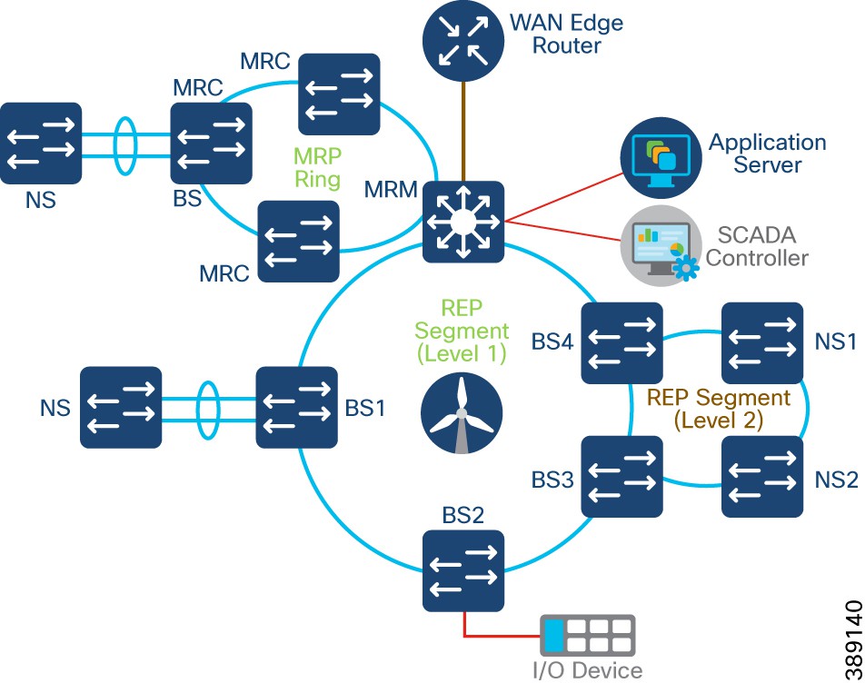 |
Turbine SCADA Network (TSN) Design with REP
In a compact substation, each wind turbine has a Cisco IE3400 switch deployed at the turbine nacelle for SCADA controller connectivity to various SCADA endpoints in the compact substation. These endpoints include SCADA devices, IEDs, I/O devices, and so on.
TSN design in a compact substation is same as converged turbine operator network TSN design. Refer to the section, “Turbine SCADA Network (TSN) Design” for more details on TSN design options.
Compact Substation Network Security
This section discusses the turbine operator network security design in a compact onshore substation.
Compact Substation Network Segmentation using Private VLAN
In a compact substation, FSN and TSN are micro-segmented using Private VLANs. Compact substation Private VLAN design is same as the converged turbine operator network Private VLAN design discussed in the section, “Network micro-segmentation using Private VLAN”.
Private VLANs are configured in the compact onshore substation core network (substation location or inside network) for SCADA traffic and propagated to all the switches in the FSN and TSN using VLAN Trunk Protocol (VTP) version 3. IE core switch is configured in VTP server mode with all VLANs configured for the entire VTP domain. All IE3400 switches in FSN and TSN are configured in client mode to receive VLAN details via VTP.
For more details, see VLAN Trunk Protocol.
Zone Based Firewall (ZBFW) Design
The main goal for segmentation is to minimize the impact of any potential breach. Private VLANs in a compact substation provides network segmentation within substation local or inside network. However, the risk of breach remains to data center or substation local network from outside or DMZ networks via WAN edge. Malware could be introduced to the network using rogue USBs, or infected devices connecting to plant floor infrastructure. This section provides design guidance to further segment the network into smaller trust zones, so if an adversary does breach the network boundary, their effectiveness can be reduced and contained.
A zone is a collection of physically and functionally united assets that have similar security requirements. These areas are defined form the physical and functional models of compact substation network architecture. Some characteristics of a security zone are:
● A zone should have a clear border
● A zone can have other subzones
● The border is used to define access with another zone or outside system
● Access is via electronic communication channels or the physical movement of people or equipment
A conduit or Zone policy supports the communication between zones. A zone policy supports and defines allowed communication between two or more zones. Some attributes defined within a zone policy are:
● The zones interconnected by the conduit
● Type of dataflows allowed
● Security policies and procedures
Partitioning the compact substation network into zones and zone policies reduces overall security risk by limiting the scope of a successful cyber-attack.
Cisco IOS Classic Firewall stateful inspection (formerly known as Context-Based Access Control, or CBAC) employed an interface-based configuration model, in which a stateful inspection policy was applied to an interface. All traffic passes through that interface received the same inspection policy. This configuration model limited the granularity of the firewall policies and caused confusion of the proper application of firewall policies, particularly in scenarios when firewall policies must be applied between multiple interfaces.
Zone-Based Policy Firewall (also known as Zone-Policy Firewall, or ZFW) changes the firewall configuration from the older interface-based model to a more flexible, more easily understood zone-based model. Interfaces are assigned to zones, and inspection policy is applied to traffic that moves between the zones. Inter-zone policies offer considerable flexibility and granularity, so different inspection policies can be applied to multiple host groups connected to the same router interface.
A security zone must be configured for each region of relative security within the network, so that all interfaces that are assigned to the same zone are protected with a similar level of security. For example, Figure 77 shows two basic security zones inside and outside configured on a Cisco IR1101.
● One interface on the router is connected to the public Internet
● Two interfaces are connected to a private LAN (VLAN1) that must not be accessible from the public Internet
● Each interface in this network is assigned to its own zone, although you can want to allow varied access from the public Internet (Outside) to specific hosts in the Inside zone and varied application use policies for hosts in the protected LAN.
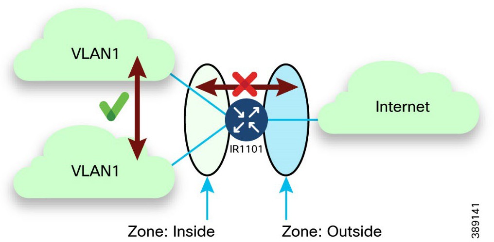 |
For more details, see Zone Based Firewall.
In a compact onshore substation, following five security zones are configured on the WAN edge Cisco IR1101 router with interfaces assigned to them, as shown in Figure 79.
● Inside Zone – Onshore substation local network interface on IR1101 connected to the core switch
● FlexVPN Zone – FlexVPN tunnel interface on IR1101 for DC connectivity
● Outside Zone – WAN interface on IR1101 with access to Internet
● DMZ zone – Utility DMZ zone interface on IR1101 with access to SCADA applications like OPC-UA gateway, SCADA Client etc.,
● Customer zone – Customer network interface on IR1101 with access to customer applications protocols traffic
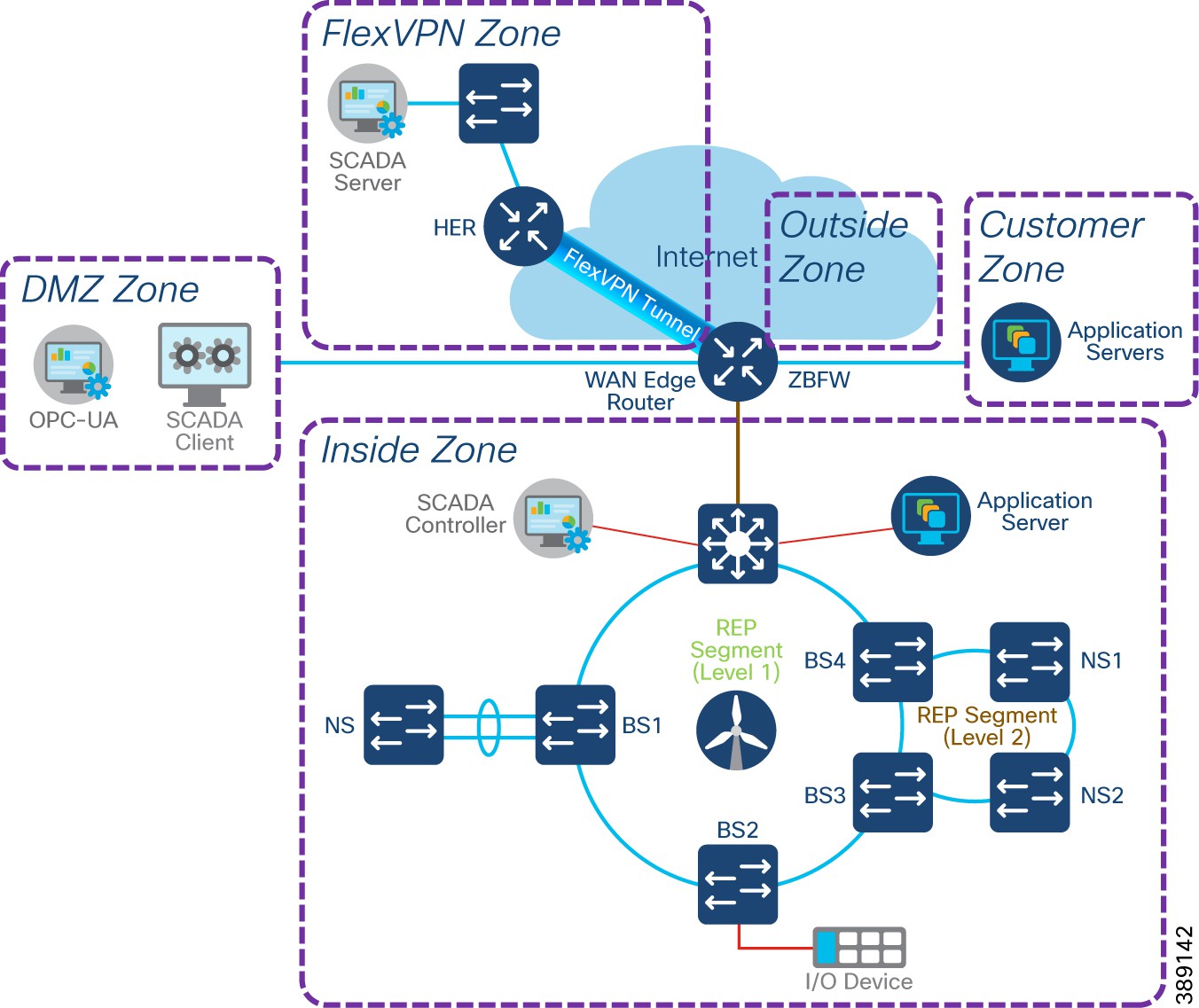 |
● A security zone for each region of relative security within the network; All interfaces in a same zone are protected with same level of security
● Zone Pair configuration defines the traffic that must be allowed between zones
● Class-map configurations on IR1101 define the traffic for ZBFW policy application. Layer 4 Class-maps sort the traffic based on the following criteria
● Access-group – a standard or extended named ACL that filters traffic based on source and destination IP address, source and destination Port number
● Protocol – L4 protocols such as TCP, UDP, ICMP and application services like HTTP, FTP, SMTP, DNS, Syslog etc.,
● Class-map – a subordinate class map that is nested inside a class-map for additional match criteria
An example zone pair policy from a compact substation DMZ zone to Inside zone could allow application protocols traffic like OPC-UA, ms-sql,ftp,ftps, ftpes, ICMP etc., and layer 4 protocols traffic on specific TCP port numbers (8006,8007,9091,9093).
Table 20 lists example security zones and zone pair policy configuration requirements between zones in a secure turbine operator compact onshore substation.
Table 20. Example Zone-pair security policy requirements between zones in Compact Substation
| Zone/ Destination Source |
Inside |
FlexVPN |
DMZ |
Outside |
Customer |
| Inside |
Default: allow all |
Permit: Specific Inside addresses to FlexVPN addresses and application protocols traffic |
Permit: All inside network FTP traffic |
Permit: access to VPN gateways and VPN protocols (https,ipsec,isakmp), Internet & specific UDP |
Permit: Specific Inside addresses to Customer network addresses and application protocols traffic |
| FlexVPN |
Permit: Specific FlexVPN addresses to Inside site addresses, Syslog protocol and specific TCP ports |
Default: allow all |
Deny |
Deny |
Deny |
| DMZ |
Permit: DMZ clients to ms-sql,ftp,ftps,ftpes, & TCP Ports - 8006 8007 9091 9093, OPC-UA Port - 62550 & ICMP |
Deny |
Default: allow all |
Deny |
Deny |
| Outside |
Deny |
Deny |
Deny |
Default: allow all |
Permit: Internet return traffic |
| Customer |
Permit: Specific Customer network addresses to Inside addresses |
Deny |
Deny |
Permit: access to Internet & specific UDP |
Default: allow all |
Network Visibility using NetFlow
Network visibility is the foundation for continuous monitoring to gain awareness of what is happening in the network. Complete visibility is critical to making proactive decisions and getting to resolutions as quickly as possible. Network threat defense is for preventing threats from the external network entering the internal network or to identify suspicious network traffic patterns within the network. NetFlow can be enabled on all network switches in Compact ONSS for,
● Visibility of network contexture awareness and content awareness
● Monitor and analyze network traffic for malicious activity or for other actions that violate an organization's security policies
● Threat detection and mitigation
NetFlow is a network protocol system created by Cisco that collects active IP network traffic as it flows in or out of an interface. NetFlow is now part of the Internet Engineering Task Force (IETF) standard (RFC 3954) as Internet Protocol Flow Information eXport (IPFIX, which is based on NetFlow Version 9 implementation), and the protocol is widely implemented by network equipment vendors.
NetFlow is an embedded instrumentation within Cisco IOS Software to characterize network operation. Visibility into the network is an indispensable tool for IT/OT professionals. NetFlow is a protocol that creates flow records for the packets flowing through the switches and the routers in a network between the end devices and exports the flow records to a flow collector. The data collected by the flow collector is used by different applications to provide further analysis.
The Cisco Industrial Ethernet (IE) 3400 switch and Cisco IR1101 WAN edge router support full Flexible NetFlow. Each packet that is forwarded within a router or switch is examined for a set of IP packet attributes. These attributes are the IP packet identity or fingerprint of the packet and determine if the packet is unique or similar to other packets.
Traditionally, an IP Flow is based on a set of 5 and up to 7 IP packet attributes. All packets with the same source/destination IP address, source/destination ports, protocol interface and class of service are grouped into a flow and then packets, and bytes are tallied. This methodology of fingerprinting or determining a flow is scalable because a large amount of network information is condensed into a database of NetFlow information called the NetFlow cache.
With the latest releases of NetFlow v9, the switch or router can gather additional information such as ToS, source MAC address, destination MAC address, interface input, interface output, and so on.
As network traffic traverses the IE switches and IR1101 in the compact substation, flows are continuously created and tracked. As the flows expire, they are exported from the NetFlow cache to the Flow Collector(s) in the inside network zone and FlexVPN zone, as shown in Figure 79. A flow is ready for export when it is inactive for a certain time (for example, no new packets are received for the flow) or if the flow is long lived (active) and lasts greater than the active timer (for example, long FTP download and the standard TCP/IP connections). There are timers to determine whether a flow is inactive, or a flow is long lived.
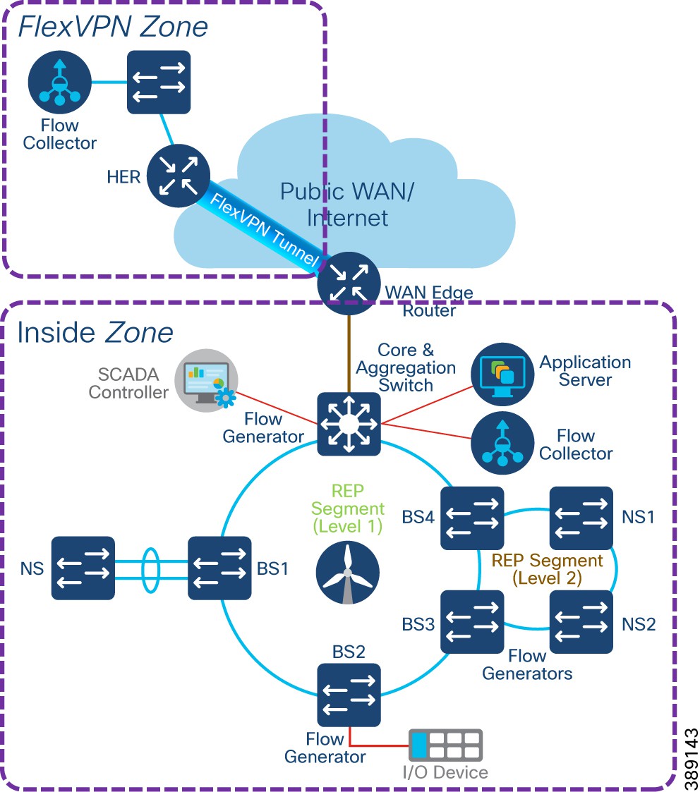 |
In the compact substation network, it is recommended to enable NetFlow monitoring for security on all interfaces of FSN, TSN IE3400 switches, core switch and IR1101 WAN edge router in the network.
Compact Substation Quality of Service
Turbine operator’s compact onshore substation Quality-of-Service (QoS) design is same as QoS design discussed in the section, “TSN Quality-of-Service Design”.
It is recommended to refer the QoS design in the section, “TSN Quality-of-Service Design” for the core IE3400 switch QoS design for different classes of traffic with ingress classification & marking and egress queuing. WAN edge router (IR1101) QoS design is out of scope of this design, as it depends on WAN/Internet Service Provide QoS policy implementation at egress WAN port on IR1101.
Design Considerations on Core Switch
● Cisco IE3400 and IE3100 switches in the TSN and FSN support one priority queue, seven class based queues, and two QoS thresholds (1P7Q2T) at each egress interface. However, depending on the turbine operator network SCADA and other OT traffic flows and its priority, traffic mapping at egress queues in the IE switches is performed as per the QoS design by using 4 traffic classes and egress queues.
● Ingress traffic classification is based on IP ACLs (or IP address of the source device) depending on the traffic type and mark the DSCP value for the ingress traffic at IE switch.
● DSCP values of EF, CS4, CS2 and default marking is done at ingress for critical, high priority, medium and low priority traffic flows respectively for the traffic from various SCADA devices in the turbine operator network.
● Each egress interface in the TSN and FSN in turbine operator network is mapped with a queuing policy, as per the QoS design.
● Strict priority queueing is considered for critical devices or LLQ traffic with low buffer queue size (to ensure priority treatment over other classes of traffic) in case of network congestion and remaining bandwidth is shared for other classes of traffic.
Cisco is a global leader in industrial networking and provides a wide range of products to address the offshore renewable energy market. By applying our secure and hardened industrial networking, IoT expertise, and experience working with industry leaders to address challenges existing in the industry, we have created innovative technology solutions that optimize and secure renewable energy assets.
Our goal is to future-proof your investment by providing an evolution path from today’s isolated deployments to secure, connected renewable energy deployments that support the energy needs of today and tomorrow.
Since the inception of IP networking, Cisco Validated Designs (CVDs) have been used to validate, architect, and configure industry best practices and technology solutions. CVDs start with solution use cases and architect the flow from the edge device to the application, validating key Cisco and third-party components along the way. Each aspect of the architecture is thoroughly tested and documented with sample configurations, helping to simplify integration and de-risk implementations through proven solutions.
The goal is to ensure a deployment and a solution that’s simple, fast, reliable, secure, and cost effective. Cisco developed renewable energy network solutions to specifically address the networking and security needs of renewable energy asset operators.
The following table summarizes the acronyms and initialisms that may be used in this document.
Table 21. Acronyms and initialisms
| Term |
Definition |
| AAA |
Authentication, authorization, and accounting |
| ACL |
Access control list |
| AD |
Active Directory |
| ADM |
Axis Device Manager |
| AIS |
Automatic identification system |
| AP |
Access point |
| AMP |
Advanced malware protection |
| ARP |
Address resolution protocol |
| AVC |
Application visibility and control |
| BGP |
Border gateway protocol |
| BS |
(Turbine) base switch |
| BW |
Bandwidth |
| CA |
Certificate authority |
| CAK |
Connectivity Association Key |
| CBWFQ |
Class-based weighted fair queuing |
| CC |
Control center |
| CCTV |
Closed circuit television |
| CDN |
Cisco Developer Network |
| CE |
Carrier Ethernet |
| CLI |
Command line interface |
| CoS |
Class of service |
| CTS |
Cisco TrustSec |
| URWB |
Cisco Ultra Reliable Wireless Backhaul |
| CV |
(Cisco) Cyber Vision |
| CVC |
Cisco Cyber Vision Center |
| CVD |
Cisco Validated Design |
| DAD |
Dual active detection |
| DC |
Data center |
| DHCP |
Dynamic host configuration protocol |
| DMZ |
Demilitarized zone |
| DNS |
Domain name system |
| DODAG |
Destination oriented directed acrylic graph |
| DoS |
Denial of service |
| DSCP |
Differentiated services code point |
| ECC |
Elliptic curve cryptography |
| ECMP |
Equal-cost multi path |
| EIGRP |
Enhanced interior gateway routing protocol |
| EN |
Extended nodes |
| EPs |
Endpoints |
| FAN |
Farm area network |
| FAR |
Field area routers |
| FSN |
Farm area SCADA network |
| FC |
Fiber channel |
| FCAPS |
Enhanced fault, configuration, accounting, performance, and security |
| FM |
FluidMesh |
| FMC |
Firepower Management Center |
| FNF |
Flexible NetFlow |
| FP |
Firepower |
| FW |
Firewall |
| HA |
High availability |
| HER |
Headend router |
| HMI |
Human machine interface |
| HSRP |
Hot standby touter protocol |
| HQ |
Headquarter |
| HQoS |
Hierarchical quality of service |
| IA |
Industrial automation |
| IE |
(Cisco) Industrial Ethernet |
| IEC |
International Electrotechnical Commission |
| IED |
Intelligent end device |
| IKE |
Internet key exchange |
| ISE |
Identity Services Engine |
| IOT |
Internet of things |
| I/O |
Input and output device |
| IP |
Internet protocol |
| IPSec |
Internet protocol security |
| IR |
(Cisco) Industrial Routers |
| IT |
Information technology |
| L3VPN |
Layer 3 virtual private network |
| LAN |
Local area network |
| 4G LTE |
Fourth generation long-term evolution |
| MAC |
Media access control |
| MACsec |
Media Access Control Security |
| MKA |
MACsec Key Agreement |
| MQC |
Modular QoS CLI |
| ME |
Mesh end |
| MMS |
Manufacturing message specification |
| MPLS |
Multi-protocol label switching |
| MP |
Mesh point |
| MRP |
Media redundancy protocol |
| MSK |
Master session key |
| MTU |
Maximum transmission unit |
| NAT |
Network address translation |
| NBAR2 |
Cisco Next Generation Network-Based Application Recognition |
| NGFW |
Next general firewall |
| NGIPS |
Next-Generation Intrusion Prevention System |
| NMS |
Network management system |
| NOC |
Network operation center |
| NS |
(Turbine) nacelle switch |
| NTP |
Network time protocol |
| OAM |
Operations, administration, and management |
| OEM |
Original equipment manufacturer |
| OFTO |
Offshore transmission owner |
| OPC UA |
Open Platform Communications Unified Architecture |
| OSPF |
Open shortest path first |
| OSS |
Offshore substation |
| ONSS |
Onshore substation |
| OT |
Operational technology |
| PAN |
Policy administration node; personal area networks |
| PAgP |
Port aggregated protocol |
| PHB |
Per hop behavior |
| PEP |
Policy enforcement point |
| PKI |
Public key infrastructure |
| PLC |
Power line communication |
| PnP |
Plug-and-play |
| PoP |
Point of presence |
| PoE |
Power over Ethernet |
| PQ |
Priority queuing |
| PRP |
Parallel redundancy protocol |
| PTP |
Precision Time Protocol |
| pxGrid |
Platform eXchange grid |
| QoS |
Quality of service |
| RADIUS |
Remote authentication dial-In user service |
| REP |
Resilient Ethernet protocol |
| RTU |
Remote terminal unit |
| SA |
Substation automation |
| SCADA |
Supervisory control and data acquisition |
| SD-WAN |
Software-defined wide area network |
| SEA |
Secure Equipment Access |
| SFC |
Secure Network Analytics Flow Collector |
| SGTs |
Security group tags |
| SGACL |
Security group-based access control list |
| SIEM |
Security Information and Event Management |
| SLC |
Street light controller |
| SMC |
Secure network analytics management console |
| SOV |
Service operations vessel |
| SSID |
Service set identifier |
| SSM |
Software security module |
| STP |
Spanning tree protocol |
| SVI |
Switched virtual interface |
| SVL |
StackWise virtual link |
| SXP |
SGT eXchange protocol |
| TAN |
Turbine area network |
| TBN |
Turbine base network |
| TSN |
Turbine SCADA network |
| TCP |
Transmission control protocol |
| TFTP |
Trivial file transfer protocol |
| TLS |
Transport layer security |
| TLV |
Type length value |
| UCS |
Cisco Unified Computing System |
| UDP |
User datagram protocol |
| UHF |
Ultra-high frequency |
| VHF |
Very high frequency |
| VN |
Virtual network |
| VoD |
Video-on-demand |
| VoIP |
Voice over internet protocol |
| VRF |
Virtual routing and forwarding |
| VLAN |
Virtual LAN |
| VPN |
Virtual private network |
| WAN |
Wide area network |
| WF |
Wind farm |
| Wi-Fi |
Wireless fidelity |
| WLC |
Wireless LAN controller |
| WLAN |
Wireless local area network |
| WPAN |
Wireless personal area network |
| WRED |
Weighted random early detect |
| WTD |
Weighted tail drop |
| WTG |
Wind turbine generator |
| ZTD |
Zero touch deployment |
| ZTP |
Zero touch provisioning |