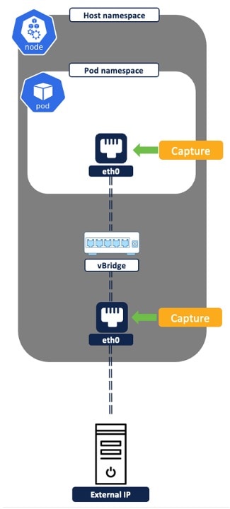
Visibility into Kubernetes Inventory and Network Flows

The Secure Workload Connector or Orchestrator offers real-time visibility and monitoring for every pod or service within the Kubernetes cluster. It ensures continuous tracking and updating of any changes in the Kubernetes inventory. For example, when a new pod is added to the cluster or a new label key-value is introduced to an existing pod, the inventory change appears immediately and in near real-time.

Core benefits of real-time visibility are:

  • Visibility into inventory at a granular level is crucial for creating effective security policies that align with the organization's requirements and compliance standards.

  • Visibility helps to trace the flow of traffic, identify affected workloads, and understand the extent of incidents for effective remediation.

Scenario

A Network Security Engineer in an Enterprise Financial Organization faces challenges in ensuring the security of Kubernetes or OpenShift clusters. These challenges include enforcing network policies, implementing traffic segmentation, mitigating potential vulnerabilities, addressing complex network architectures, and continuous monitoring for emerging security threats within and between clusters.

Is this use case for you?

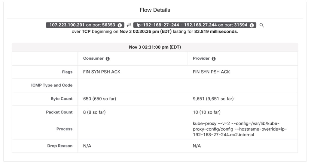
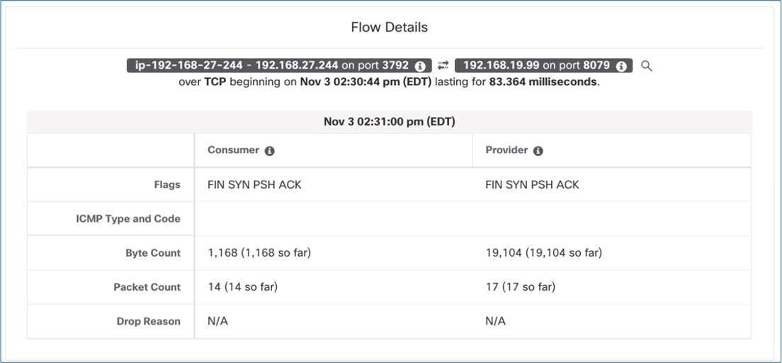
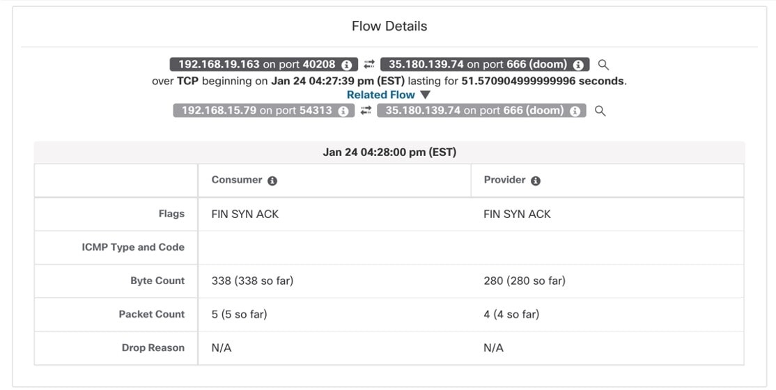
The target audience for this use case includes DevOps engineers, security analysts, and cloud and network security engineers. Their responsibilities include continuously monitoring and securing containerized environments, and using container security tools to detect and respond to potential threats and vulnerabilities.

Prerequisites

  • Ensure that you have access to the Kubernetes cluster where the workloads are deployed.

  • Verify the supported Kubernetes and OpenShift versions. For more information, see the Compatibility Matrix.

How Does Visibility Into Kubernetes Inventory and Network Flow Solve the Problem?

Dynamic monitoring of pod and service IP addresses and the associated metadata, helps construct dynamic policy objects in Secure Workload. This support enables the creation of dynamic microsegmentation policies. As a result, the system provides responsive and adaptive security measures that adjust to real-time changes in the Kubernetes environment.

Network Topology

The Secure Workload node agent or Daemonset delivers real-time visibility into network flows and provides granular details, such as TCP or UDP flags, bytes exchanged, and packet counts for each network connection. Labels from the Kubernetes inventory further enhance the flows.

The Secure Workload agent or pod, deployed on each node, captures traffic or flows from two sources: the pod network interface and the host network interface. The set of captured network flows varies based on the type of network communication. Network communications in a Kubernetes cluster can be grouped into these main categories:

Pod-to-Pod Network Flows (Intra-Node)

Connections between pods can occur either directly or through a Kubernetes service, specifically ClusterIP. The way flows are recorded depends on the nature of the connection.
Figure 1. Pod-to-Pod network flows (Intra Node)
  • In a direct connection between Pod1 and Pod2, the system logs a singular flow with Pod1 as the source and Pod2 as the destination. Both the source and destination pod network interface cards (NIC) capture this information; however, the Secure Workload cluster deduplicates the flow because it represents the same data recorded at two points.

  • In the Pod1-to-Pod2 connection using a Kubernetes service (ClusterIP), two sets of network flows are documented:

    • The first network flow is reported with the source as Pod1 NIC IP and the destination as the ClusterIP Service IP. This flow is captured at the source Pod NIC.

    • After the flow leaves Pod1 NIC, the system applies DNAT (Destination Network Address Translation) in the host namespace. This process changes the destination address to Pod2's IP. The system captures the second network flow at both the node NIC and Pod2 NIC. Because this flow represents the same network data, the Secure Workload cluster deduplicates it. The system then reports the flow with Pod1 NIC as the source and Pod2 NIC as the destination.

Figure 2. Pod-to-Pod Network Flows using Service (Intra Node)
A network-monitoring dashboard showing a single TCP flow from consumer IP 192.168.59.21 on port 60824 to provider IP 192.168.38.189 on port 80 (HTTP). The Flow Details panel displays the start time, total duration of 902.001 milliseconds, and both consumer and provider have flags FIN SYN PSH ACK, byte counts of 690 and 888 respectively, packet counts of 10 each, and drop reason for N/A

Pod-to-Pod Network Flows (Inter Node)

Inter-node pod-to-pod connections can occur either directly or using a Kubernetes service (specifically, ClusterIP). The recorded flows differ based on the nature of the connection.

Figure 3. Pod-to-Pod Network Flows (Inter Node)
  1. In a direct connection between Pod1 and Pod2, a single flow is logged with the source as Pod1 and the destination as Pod 2.

  2. In a Pod1 to Pod2 connection through a Kubernetes service (Type ClusterIP), two sets of network flows are logged. In this scenario, a node-to-node flow is not recorded in this scenario.

    1. The first network flow is captured with the source as Pod1 NIC IP and the destination as the Service NIC IP. This is captured at thesource Pod1 NIC.

    2. After the flow leaves Pod1 NIC, it undergoes DNAT (Destination Network Address Translation) in the host namespace, which changes the destination address to Pod2 IP. The second network flow is captured at Node1 NIC, Node2 NIC, and Pod2 NIC. These flows are deduplicated since they represent the same flow. The reported flowhas the source as Pod1 NIC and the destination as Pod2 NIC.

Figure 4. Pod-to-Pod using Service (Inter Node)

External IP to Pod Network Flows

For external IP to Pod network flow, when pods are exposed to any external IP (outside the cluster) by using Node Port or Load Balancer service, the system captures two sets of flows. Node Port and Load Balancer Kubernetes Services are functionally similar. However, Load Balancer provides additional automation for public cloud load balancing and fronts the Kubernetes cluster nodes.

Figure 5. External IP to Pod Network Flows

From a flow reporting perspective, in both scenarios, the following two sets of flows are captured for any external IP to pod communications:

  1. External IP to Node IP: Node port captured at Node NIC: After entering the cluster, the flow undergoes Network Address Translation (NAT) and is reported with the source as the Node IP or Load Balancer IP and the destination as the pod IP. This represents the flow from the Node or Load Balancer to the specific pod within the cluster.

  2. Node IP to Pod IP: Pod port captured at Pod NIC: After entering the cluster, the flow undergoes Network Address Translation (NAT) and is reported with the source as the Node IP or Load Balancer IP and the destination as the pod IP. This represents the flow from the Node or Load Balancer to the specific pod within the cluster.

Figure 6. External IP to Pod Network Flow

Pod to External IP Flows

In pod-to-external IP network flows, two sets of network flows are reported, one from the source pod network interface (NIC) and the second from the node NIC.

Figure 7. Pod to External IP Flows
  • The first flow is captured and logged from the source Pod NIC. The flow source is the Pod IP, and the destination is the external IP. The flow undergoes source NAT translation in the host namespace before it leaves the node NIC.

  • The second flow is captured and logged from the node NIC. The flow source is the node IP, and destination as external IP.

Figure 8. Pod to External IP Flows

For more information, see Network Flows - Traffic Visibility.