Features
The Cisco Secure Firewall 1200 series is a family of network security appliances for enterprise branches. The appliances are powered by a network processor that delivers high performance and power efficiency in modern branch security workloads. The 1200 Series includes three 1U rack-mount models: 1230, 1240 and 1250. The Secure Firewall 1200 series supports Cisco Secure Firewall Threat Defense and Cisco Secure Firewall ASA software.
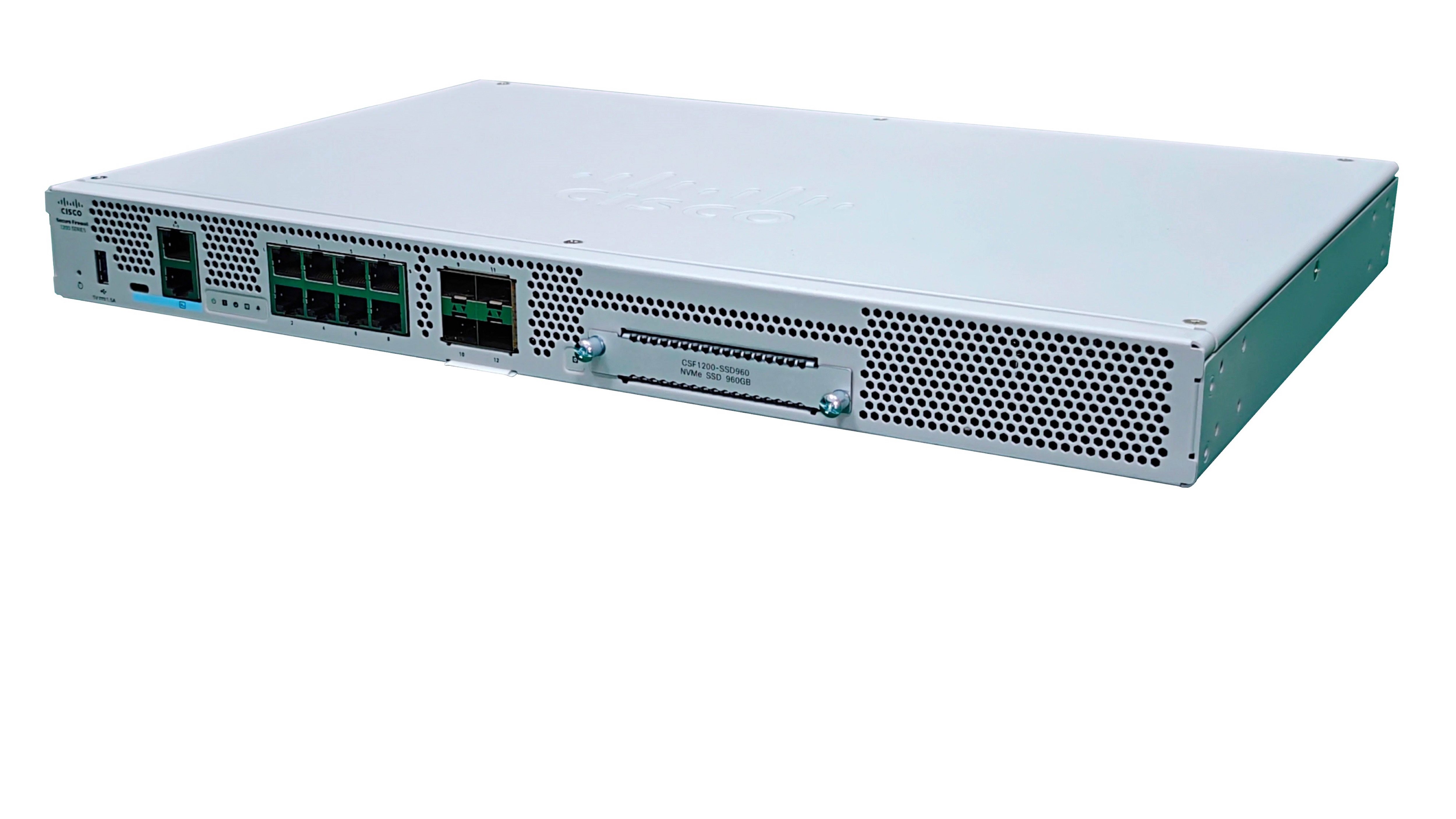
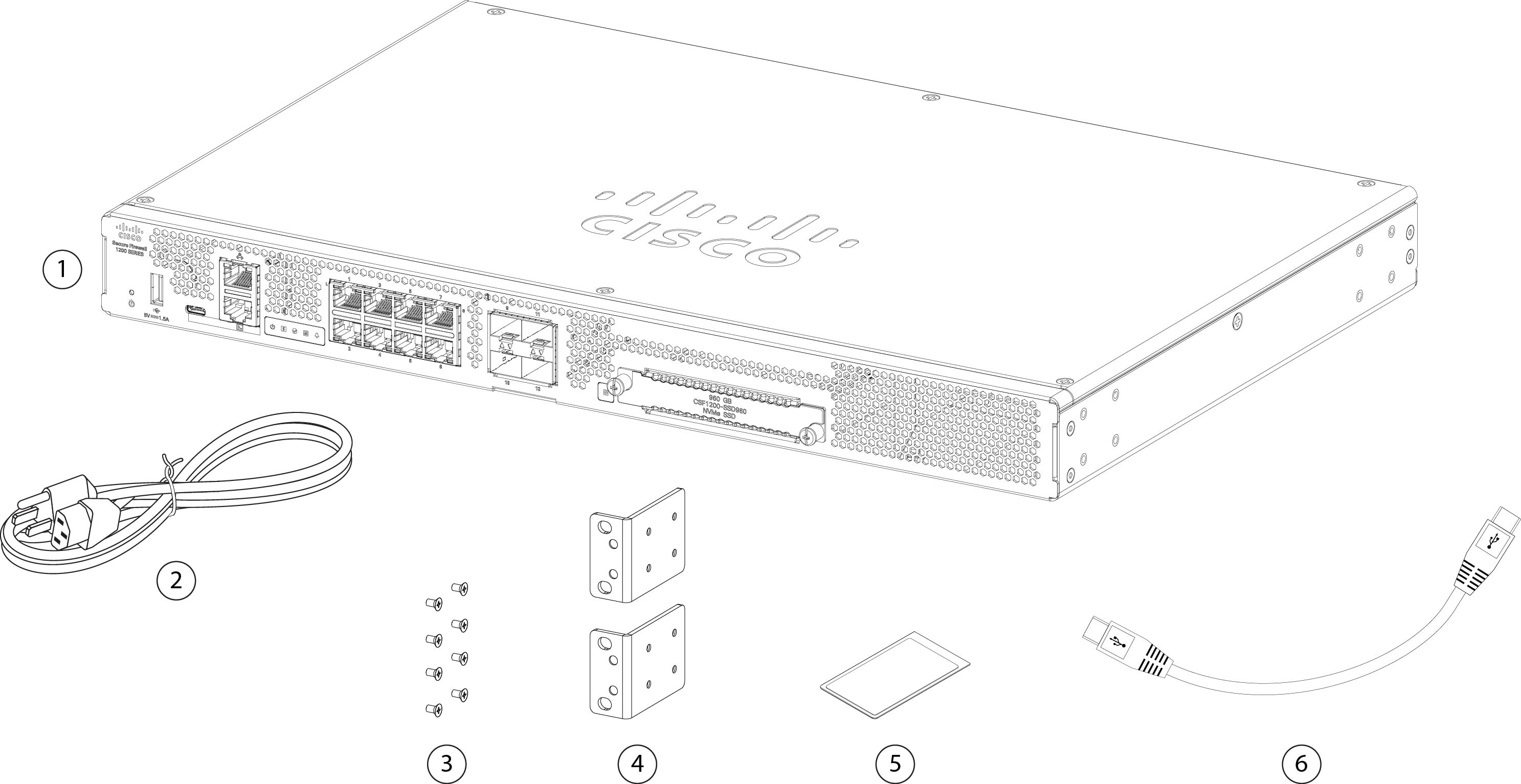
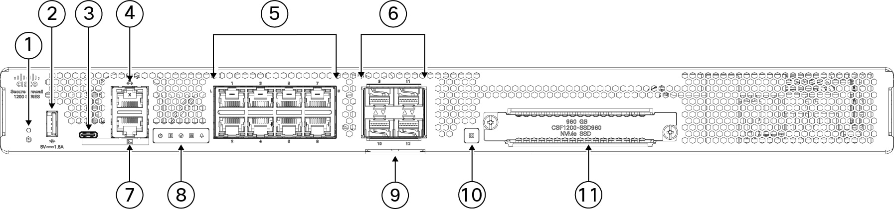
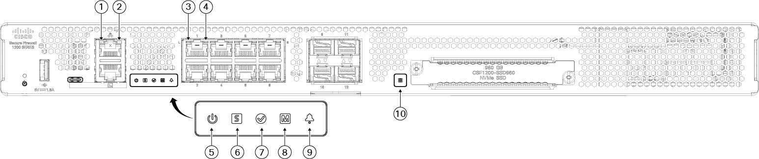
The following figure shows the Cisco Secure Firewall 1200 series chassis.
The following table lists the features for the Secure Firewall 1200 series.
|
Feature |
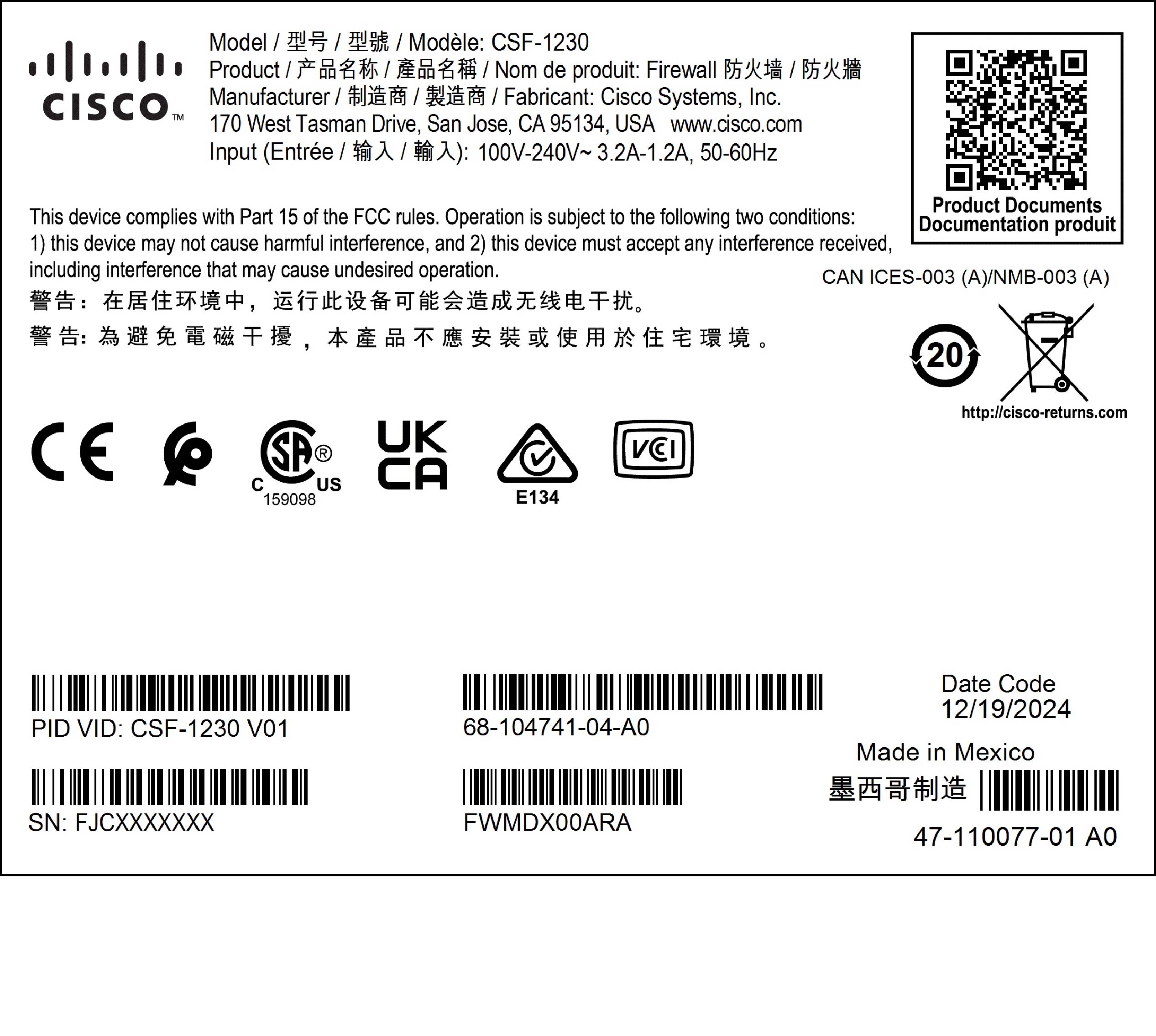
CSF-1230 |
CSF-1240 |
CSF-1250 |
||||
|---|---|---|---|---|---|---|---|
|
Form factor |
1 RU |
||||||
|
Mounting |
Rack mount EIA-310D (19-inch) rack (2-post mounting) |
||||||
|
Airflow |
I/O side to non-I/O side with I/O side air intake Rear panel to front panel (cold aisle to hot aisle) |
||||||
|
System memory |
16 GB |
32 GB |
|||||
|
Management port |
One 1-Gbps copper RJ-45 Gigabit Ethernet 10/100/1000 BaseT Restricted to network management access only; connect with an RJ-45 cable |
||||||
|
Console ports |
One Cisco Serial (RS-232 on RJ-45) One USB Type C 3.0 Provides management access through an external system; you cannot use both ports at the same time. |
||||||
|
USB port |
One USB 3.0 Type A Allows attachment of an external device such as mass storage |
||||||
|
Network ports |
Eight 1000BaseT1 |
Eight 1000/2500 BaseT2 |
|||||
|
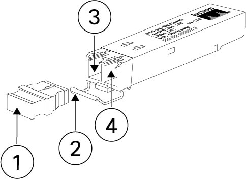
Small form-factor pluggable (SFP) ports |
Four SFP+ (1/10Gbps) Port numbering is left to right, top to bottom; ports are named Gigabit Ethernet 1/9 through 1/12. Each port includes a pair of LEDs, one each for connection status and link status. |
||||||
|
Supported SFPs |
See Supported transceivers for a list of the supported SFPs. |
||||||
|
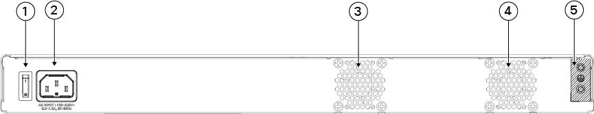
Power switch |
Yes On rear panel; rocker-type power on/off switch
|
||||||
|
Reset button |
Small recessed button Push and hold with a pin for 5 seconds; resets the chassis to its default state following the next reboot.
|
||||||
|
AC power supply |
One AC power supply Internal component only; not field-replaceable. You must return the chassis to Cisco for power supply replacement. |
||||||
|
Redundant power |
No |
||||||
|
Fan |
Two fixed fans The fans are internal; there is no user access. The fan is not field-replaceable; you must return the chassis to Cisco for fan replacement. |
||||||
|
Storage |
One slot 960-GB U.2 NVME The drive is field-replaceable. |
||||||
|
Flash |
Internal 16 GB eMMC. Not field-replaceable. |
||||||


 Feedback