Rack-Mount the Chassis

Unpack and Inspect the Chassis


Note


The chassis is thoroughly inspected before shipment. If any damage occurred during transportation or any items are missing, contact your customer service representative immediately. Keep the shipping container in case you need to send the chassis back due to damage.


See Package Contents for a list of what ships with the chassis.


Caution


If you accidentally push the power switch to ON while unpacking your chassis, make sure the power switch is set to OFF before you connect AC power for the first time. The chassis powers on and boots up as soon as the AC power is applied when the power button is in the ON position. See Rear Panel for a description of the power switch and its position on the rear panel of the chassis.


Procedure


Step 1

Remove the chassis from its cardboard container and save all packaging material.

Step 2

Compare the shipment to the equipment list provided by your customer service representative. Verify that you have all items.

Step 3

Check for damage and report any discrepancies or damage to your customer service representative. Have the following information ready:

  • Invoice number of shipper (see the packing slip)

  • Model and serial number of the damaged unit

  • Description of damage

  • Effect of damage on the installation


Ground the Chassis


Note


Grounding the chassis is required, even if the rack is already grounded. A grounding pad with two threaded M4 holes is provided on the chassis for attaching a grounding lug. The grounding lug must be Nationally Recognized Testing Laboratory (NRTL)-listed. In addition, a copper conductor (wires) must be used and the copper conductor must comply with National Electrical Code (NEC) code for ampacity.

You need the following items that you provide:

  • Wire-striping tool

  • Crimping tool

  • Grounding cable

  • Two star lock washers for the 10-32 x 0.375 inch-screws used to secure the ground lug

  • You need the following items from the accessory kit:

    • Grounding lug #6 AWG, 90 degree, #10 post

    • Two 10-32 x 0.38-inch screws used to secure the grounding lug

Safety Warnings

Take note of the following warnings:


Warning


Statement 1024—Ground Conductor

This equipment must be grounded. To reduce the risk of electric shock, never defeat the ground conductor or operate the equipment in the absence of a suitably installed ground conductor. Contact the appropriate electrical inspection authority or an electrician if you are uncertain that suitable grounding is available.


Warning


Statement 1046—Installing or Replacing the Unit

To reduce risk of electric shock, when installing or replacing the unit, the ground connection must always be made first and disconnected last.

If your unit has modules, secure them with the provided screws.


Procedure


Step 1

Use a wire-stripping tool to remove approximately 0.75 inches (19 mm) of the covering from the end of the grounding cable.

Step 2

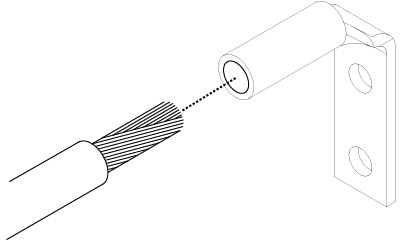
Insert the stripped end of the grounding cable into the open end of the grounding lug.

Figure 1. Insert the Cable into the Grounding Lug

Step 3

Use the crimping tool to secure the grounding cable in the grounding lug.

Step 4

Remove the adhesive label from the grounding pad on the chassis.

Step 5

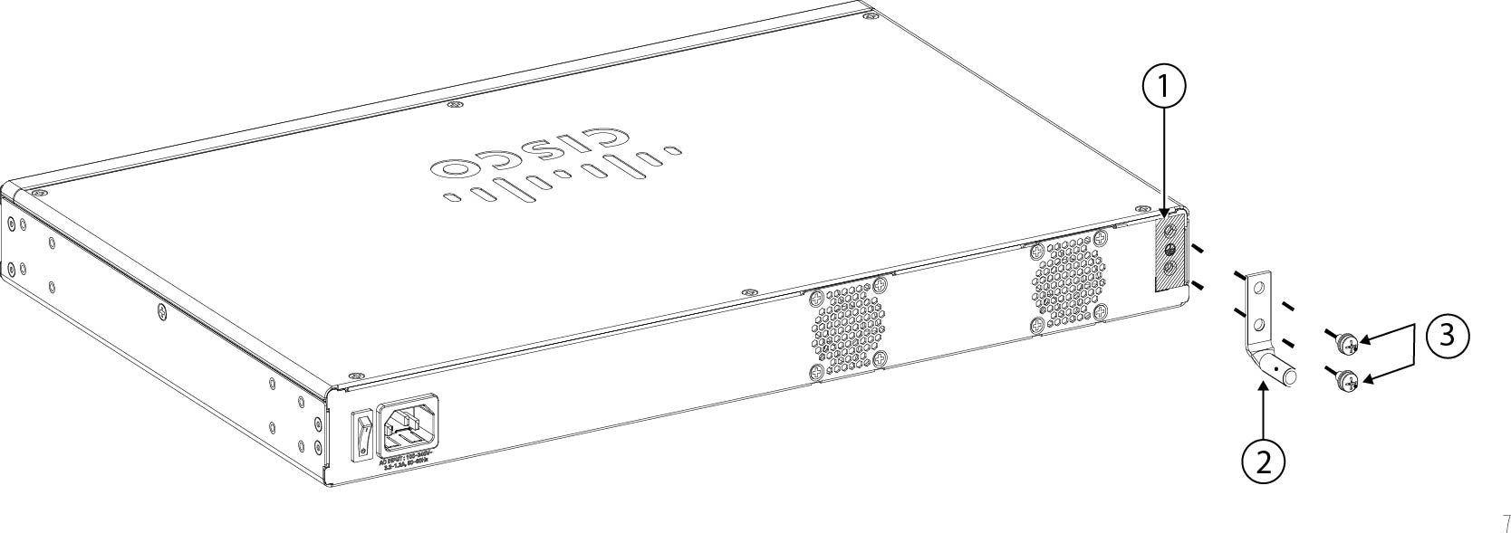
Place the grounding lug against the grounding pad so that there is solid metal-to-metal contact, and insert the two screws with washers through the holes in the grounding lug and into the grounding pad.

Figure 2. Attach the Grounding Lug

1

Grounding lug pad

2

Grounding lug

3

Two 10-32 x 0.38-inch screws

Step 6

Make sure that the lug and cable do not interfere with other equipment.

Step 7

Prepare the other end of the grounding cable and connect it to an appropriate grounding point in your site to ensure adequate earth ground.


What to do next

Install the cables according to your default software configuration as described in the getting started guide.

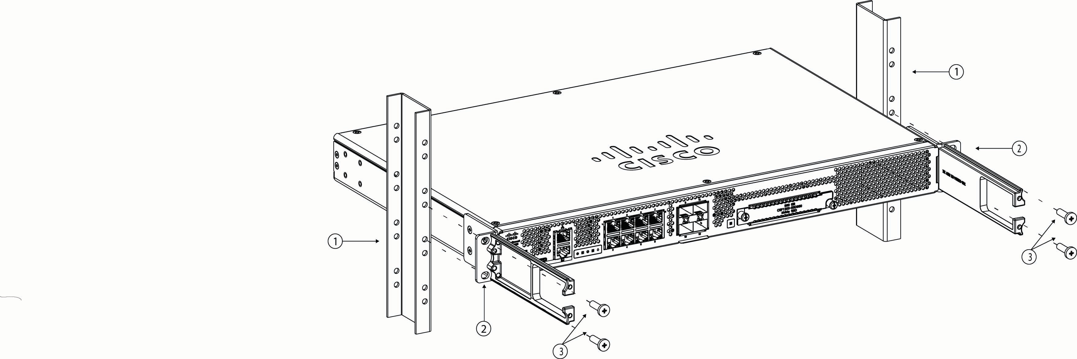
Rack-Mount the Chassis

The chassis ships with rack-mount brackets and screws that you can install on the front or the rear of the chassis. We recommend that you install them on the I/O side of the chassis (the rear panel) and then have that side facing the cold aisle. See Package Contents for the rack-mount items in the accessory kit.

The rack is a standard Electronic Industries Association (EIA) rack. It is a 4-post-EIA-310-D, which is the current revision as specified by EIA. The vertical hole spacing alternates at .50 inches (12.70 mm) to .625 inches (15.90 mm) to .625 inches (15.90 mm) and repeats. The start and stop space is in the middle of the .50-inch holes. The horizontal spacing is 18.312 inches (465.1 mm), and the rack opening is specified as a minimum of 17.75 inches (450 mm).

Procedure


Step 1

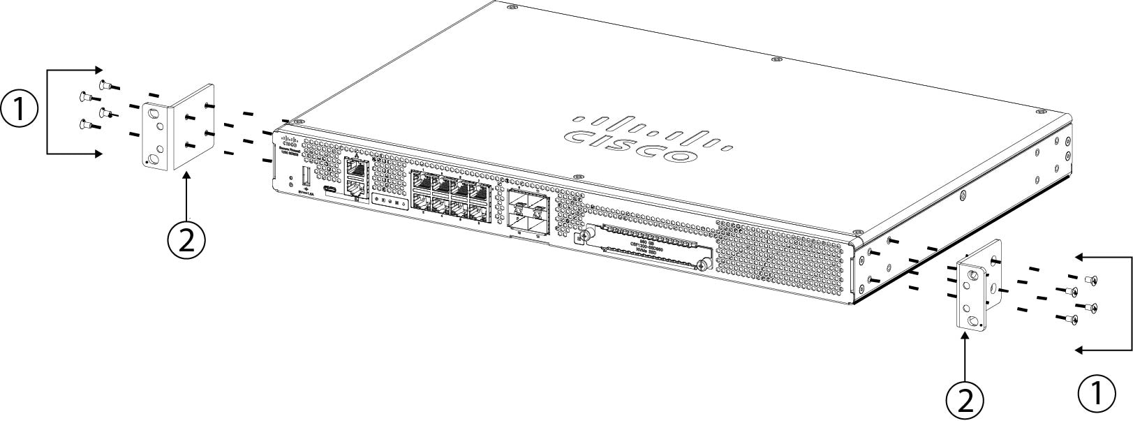
Attach both rack-mount brackets to the sides of the chassis using the eight 6-32 x 0.25-inch Phillips screws (four for each side) that shipped with your chassis. After the rack-mount brackets are secured to the chassis, you can attach the cable guides.

Figure 3. Attach the Rack-Mount Brackets to the Chassis

1

Four 6-32 x 0.25-inch Phillips screws

2

Rack-mount bracket

Step 2

(Optional) Attach the cable guides to the rack-mount brackets using the four 8-32 x 0.375-inch Phillips screws.

Figure 4. Attach the Cable Guides to the Rack-Mount Brackets

1

Rack

2

Cable management bracket

3

8-32 x 0.375-inch Phillips screws (two per bracket)

Step 3

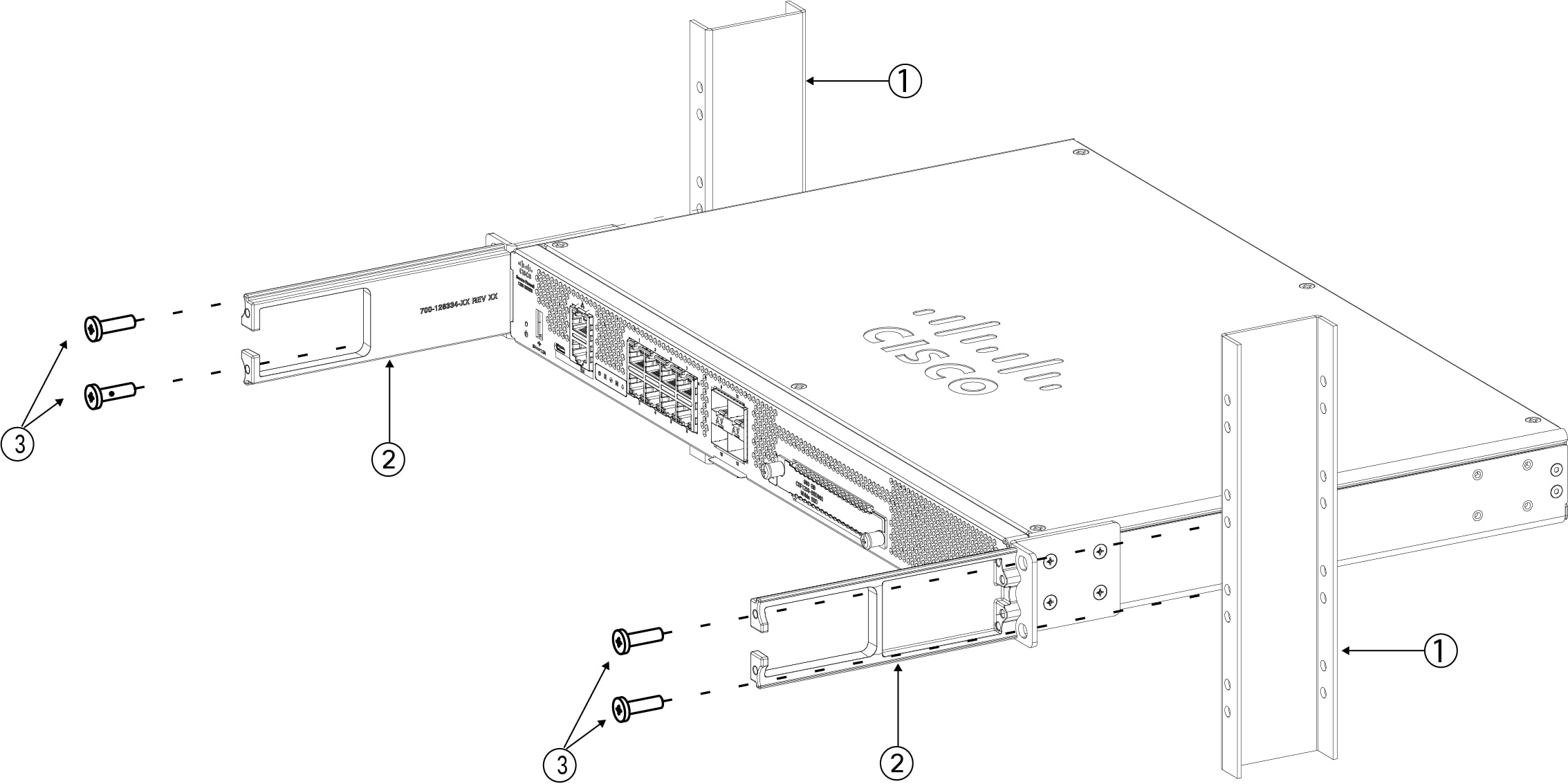
Attach the chassis to the rack using the screws that you supply for your rack type.

We recommend that you install the chassis with the I/O side (rear panel) facing the cold aisle.

Figure 5. Install the Chassis in the Rack

1

Rack

2

Rack-mount bracket

3

Rack-mount screws

Chassis I/O side (rear panel)


What to do next

You can now install the cables and power cord, as described in the getting started guide.