Deploy the ASA Virtual on KVM

You can deploy the ASA Virtual on any server class x86 CPU device that is capable of running the Kernel-based Virtual Machine (KVM).


Important


The minimum memory requirement for the ASA Virtual is 2GB. If your current ASA Virtual runs with less than 2GB of memory, you cannot upgrade to 9.13(1)+ from an earlier version without increasing the memory of your ASA Virtual machine. You can also redeploy a new ASA Virtual machine with the latest version.


Guidelines and Limitations

The specific hardware used for ASA Virtual deployments can vary, depending on the number of instances deployed and usage requirements. Each virtual appliance you create requires a minimum resource allocation—memory, number of CPUs, and disk space—on the host machine.


Important


The ASA Virtual deploys with a disk storage size of 8GB. It is not possible to change the resource allocation of the disk space.


Note


Starting from ASA Virtual Version 9.16.x, when you are downgrading from ASAv100, whose device configuration is 16 vCPU and 32GB RAM, to ASAv10, then you must configure the device with 1 vCPU and 4GB RAM.


Review the following guidelines and limitations before you deploy the ASA Virtual.

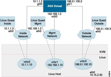
ASA Virtual on KVM System Requirements

Make sure to conform to the specifications below to ensure optimal performance. The ASA Virtual has the following requirements:

  • The host CPU must be a server class x86-based Intel or AMD CPU with virtualization extension.

    For example, ASA Virtual performance test labs use as minimum the following: Cisco Unified Computing System™ (Cisco UCS®) C series M4 server with the Intel® Xeon® CPU E5-2690v4 processors running at 2.6GHz.

Recommended vNICs

The following vNICs are recommended in order of optimum performance.

  • i40e in PCI passthrough—Dedicates the server's physical NIC to the VM and transfers packet data between the NIC and the VM via DMA (Direct Memory Access). No CPU cycles are required for moving packets.

  • i40evf/ixgbe-vf—Effectively the same as above (DMAs packets between the NIC and the VM) but allows the NIC to be shared across multiple VMs. SR-IOV is generally preferred because it has more deployment flexibility. See

  • virtio—This is a para-virtualized network driver that supports 10Gbps operation but also requires CPU cycles.


Note


ASA Virtual instance running on KVM system might encounter data connectivity issues with the SR-IOV interface using the vNIC driver i40e version 2.17.4. We recommend you upgrade this vNIC version to other versions as a workaround to fix this issue.


Performance Optimizations

To achieve the best performance out of the ASA Virtual, you can make adjustments to the both the VM and the host. See Performance Tuning for more information.

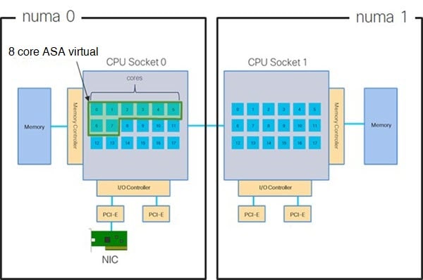
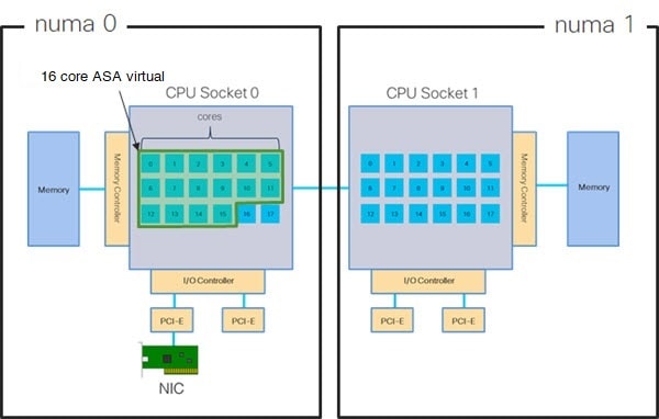
  • NUMA—You can improve performance of the ASA Virtual by isolating the CPU resources of the guest VM to a single non-uniform memory access (NUMA) node. See NUMA Guidelines for more information.

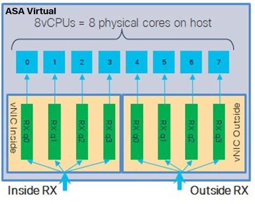
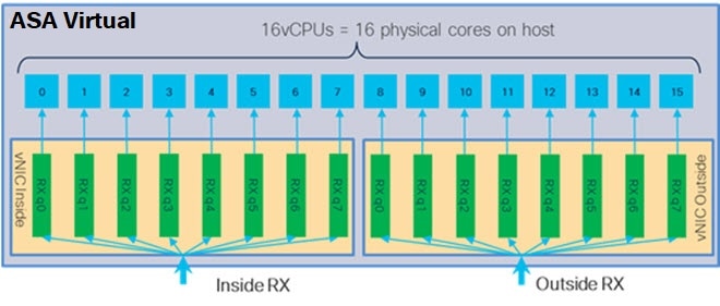
  • Receive Side Scaling—The ASA Virtual supports Receive Side Scaling (RSS), which is a technology utilized by network adapters to distribute network receive traffic to multiple processor cores. See Multiple RX Queues for Receive Side Scaling (RSS) for more information.

  • VPN Optimization—See VPN Optimization for additional considerations for optimizing VPN performance with the ASA Virtual.

Clustering

Starting from version 9.17, clustering is supported on ASA virtual instances deployed on KVM. See ASA Cluster for the ASAv for more information.

CPU Pinning

CPU pinning is required for the ASA Virtual to function in a KVM environment; see Enable CPU Pinning.

Failover for High Availability Guidelines

For failover deployments, make sure that the standby unit has the same license entitlement; for example, both units should have the 2Gbps entitlement.


Important


When creating a high availability pair using ASA Virtual, it is necessary to add the data interfaces to each ASA Virtual in the same order. If the exact same interfaces are added to each ASA Virtual, but in different order, errors may be presented at the ASA Virtual console. Failover functionality may also be affected.


ASA Virtual on Proxmox VE

Proxmox Virtual Environment (VE) is an open-source server virtualization platform that can manage KVM virtual machines. Proxmox VE also provides a web-based management interface.

When you deploy the ASA Virtual on Proxmox VE, you need to configure the VM to have an emulated serial port. Without the serial port, the ASA Virtual will go into a loop during the bootup process. All management tasks can be done using the Proxmox VE web-based management interface.


Note


For advanced users who are used to the comfort of the Unix shell or Windows Powershell, Proxmox VE provides a command line interface to manage all the components of your virtual environment. This command line interface has intelligent tab completion and full documentation in the form of UNIX man pages.


To have the ASA Virtual boot properly the VM needs to have a serial device configured:

  1. In the main management center, select the ASA Virtual machine in the left navigation tree.

  2. Power off the virtual machine.

  3. Choose Hardware > Add > Network Device and add a serial port.

  4. Power on the virtual machine.

  5. Access the ASA Virtual machine using Xterm.js.

See the Proxmox Serial Terminal page for information on how to setup and activate the terminal on the guest/server.

IPv6 Support

For creating vNICs with IPv6 support configuration on KVM, you must create an XML file for each interface that consists of IPv6 configuration parameters. You can install vNICs with the IPV6 network protocol configurations by running these XML files using the command virsh net-create <<interface configuration XML file name>>.

For each interface, you can create the following XML file:

  • Management interface - mgmt-vnic.xml

  • Diagnostic interface - diag-vnic.xml

  • Inside interface - inside-vnic.xml

  • Outside interface - outside-vnic.xml

Example:

To create an XML file for Management interface with IPv6 configuration.
<network>
             <name>mgmt-vnic</name>
             <bridge name='mgmt-vnic' stp='on' delay='0' />
             <ip family='ipv6' address='2001:db8::a111:b220:0:abcd' prefix='96'/>
        </network>
Similarly, you must create XML file for other interfaces.
You can verify the virtual network adapters installed on KVM by running the following command.
virsh net-list
         brctl show

Upgrade Restrictions and Limitations

Revert upgrade restrictions


Caution


Revert upgrades are blocked.
  • Once upgraded to ASA Virtual 9.24 or later, downgrading to versions earlier than 9.24 is not supported.

  • The users using the ASA Virtual older than 9.24 must upgrade to 9.24 before they further upgrade to the future releases (9.25 and above).

Overview

The following figure shows a sample network topology with ASA Virtual and KVM. The procedures described in this chapter are based on the sample topology. The ASA Virtual acts as the firewall between the inside and outside networks. A separate management network is also configured.

Figure 1. Sample ASA Virtual Deployment Using KVM

Prerequisites

  • Download the ASA Virtual qcow2 file from Cisco.com and put it on your Linux host:

    http://www.cisco.com/go/asa-software


    Note


    A Cisco.com login and Cisco service contract are required.


  • For the purpose of the sample deployment in this document, we are assuming you are using Ubuntu 18.04 LTS. Install the following packages on top of the Ubuntu 18.04 LTS host:

    • qemu-kvm

    • libvirt-bin

    • bridge-utils

    • virt-manager

    • virtinst

    • virsh tools

    • genisoimage

  • ASAvU is supported from ASA 9.22.

  • Performance is affected by the host and its configuration. You can maximize the throughput of the ASA Virtual on KVM by tuning your host. For generic host-tuning concepts, see NFV Delivers Packet Processing Performance with Intel.

  • Useful optimizations for Ubuntu 18.04 include the following:

    • macvtap—High performance Linux bridge; you can use macvtap instead of a Linux bridge. Note that you must configure specific settings to use macvtap instead of the Linux bridge.

    • Transparent Huge Pages—Increases memory page size and is on by default in Ubuntu 18.04.

      Hyperthread disabled—Reduces two vCPUs to one single core.

    • txqueuelength—Increases the default txqueuelength to 4000 packets and reduces drop rate.

    • pinning—Pins qemu and vhost processes to specific CPU cores; under certain conditions, pinning is a significant boost to performance.

  • For information on optimizing a RHEL-based distribution, see Red Hat Enterprise Linux 7 Virtualization Tuning and Optimization Guide.

  • For ASA software and ASA Virtual hypervisor compatibility, see Cisco Secure Firewall ASA Compatibility.

  • OVMF package must be installed on KVM host. The sample OVMF configuration is added below for reference.

    $ cat /usr/share/libvirt/firmware/ovmf.json 
    { 
     "description": "UEFI OVMF firmware", 
      "interface-types": ["uefi"], 
      "mapping": { 
        "device": "flash", 
        "mode": "readonly", 
        "firmware": "/usr/share/OVMF/OVMF_CODE.fd" 
      }, 
      "features": { 
        "secure-boot": false 
      }, 
      "targets": [ 
        { 
          "architecture": "x86_64", 
          "machines": ["q35", "pc"] 
        } 
      ] 
    }
    $ cat /usr/share/libvirt/firmware/ovmf-secureboot.json 
    { 
      "description": "UEFI Secure Boot with OVMF", 
      "interface-types": ["uefi"], 
      "mapping": { 
        "device": "flash", 
        "mode": "readonly", 
        "firmware": "/usr/share/OVMF/OVMF_CODE.secboot.fd", 
        "nvram-template": "/usr/share/OVMF/OVMF_VARS.fd" 
      }, 
      "features": { 
        "secure-boot": true 
      }, 
      "targets": [ 
        { 
          "architecture": "x86_64", 
          "machines": ["pc", "q35"] 
        } 
      ] 
    }

Prepare the Day 0 Configuration File

You can prepare a Day 0 configuration file before you launch the ASA Virtual. This file is a text file that contains the ASA Virtual configuration applied when the ASA Virtual is launched. This initial configuration is placed into a text file named “day0-config” in a working directory you chose, and is manipulated into a day0.iso file that is mounted and read on first boot. At the minimum, the Day 0 configuration file must contain commands to activate the management interface and set up the SSH server for public key authentication, but it can also contain a complete ASA configuration.

The day0.iso file (either your custom day0.iso or the default day0.iso) must be available during first boot:

  • To automatically license the ASA Virtual during initial deployment, place the Smart Licensing Identity (ID) Token that you downloaded from the Cisco Smart Software Manager in a text file named ‘idtoken’ in the same directory as the Day 0 configuration file.

  • If you want to access and configure the ASA Virtual from the serial port on the hypervisor instead of the virtual VGA console, you should include the console serial setting in the Day 0 configuration file to use the serial port on first boot.

  • If you want to deploy the ASA Virtual in transparent mode, you must use a known running ASA config file in transparent mode as the Day 0 configuration file. This does not apply to a Day 0 configuration file for a routed firewall.


Note


We are using Linux in this example, but there are similar utilities for Windows.


Procedure


Step 1

Enter the CLI configuration for the ASA Virtual in a text file called “day0-config.” Add interface configurations for the three interfaces and any other configuration you want.

The fist line should begin with the ASA version. The day0-config should be a valid ASA configuration. The best way to generate the day0-config is to copy the relevant parts of a running config from an existing ASA or ASA Virtual. The order of the lines in the day0-config is important and should match the order seen in an existing show running-config command output.

Example:

ASA Version
!
interface management0/0
ipv6 enable
ipv6 address 2001:db8::a111:b220:0:abcd/96
nameif management
security-level 100
no shut

interface gigabitethernet0/0
ipv6 enable
ipv6 address 2001:db8::a111:b221:0:abcd/96
nameif inside
security-level 100
no shut

interface gigabitethernet1/0
ipv6 enable
ipv6 address 2001:db8::a111:b222:0:abcd/96
nameif outside
security-level 100
no shut

crypto key generate rsa general-keys modulus 4096
ssh ::/0 inside
ssh timeout 60
ssh version 2
aaa authentication ssh console LOCAL

dns domain-lookup management
dns server-group DefaultDNS
name-server 2001:4860:4860::8888

Step 2

(Optional) For automated licensing during initial ASA Virtual deployment, make sure the following information is in the day0-config file:

  • Management interface IP address

  • (Optional) HTTP proxy to use for Smart Licensing

  • A route command that enables connectivity to the HTTP proxy (if specified) or to tools.cisco.com

  • A DNS server that resolves tools.cisco.com to an IP address

  • Smart Licensing configuration specifying the ASA Virtual license you are requesting

  • (Optional) A unique host name to make the ASA Virtual easier to find in CSSM

Step 3

(Optional) Download the Smart License identity token file issued by the Cisco Smart Software Manager to your computer, copy the ID token from the download file, and put it a text file named ‘idtoken’ that only contains the ID token.

Step 4

Generate the virtual CD-ROM by converting the text file to an ISO file:

Example:

stack@user-ubuntu:-/KvmAsa$ sudo genisoimage -r -o day0.iso day0-config idtoken
I: input-charset not specified, using utf-8 (detected in locale settings)
Total translation table size: 0
Total rockridge attributes bytes: 252
Total directory bytes: 0
Path table size (byptes): 10
Max brk space used 0
176 extents written (0 MB)
stack@user-ubuntu:-/KvmAsa$

The Identity Token automatically registers the ASA Virtual with the Smart Licensing server.

Step 5

Repeat Steps 1 through 5 to create separate default configuration files with the appropriate IP addresses for each ASA Virtual you want to deploy.


Prepare the Virtual Bridge XML Files

You need to set up virtual networks that connect the ASA Virtual guests to the KVM host and that connect the guests to each other.


Note


This procedure does not establish connectivity to the external world outside the KVM host.


Prepare the virtual bridge XML files on the KVM host. For the sample virtual network topology described in Prepare the Day 0 Configuration File, you need the following three virtual bridge files: virbr1.xml, virbr2.xml, and virbr3.xml (you must use these three filenames; for example, virbr0 is not allowed because it already exists). Each file has the information needed to set up the virtual bridges. You must give the virtual bridge a name and a unique MAC address. Providing an IP address is optional.

Procedure


Step 1

Create three virtual network bridge XML files. For example, virbr1.xml, virbr2.xml, and virbr3.xml:

Example:


<network>
<name>virbr1</name>
<bridge name='virbr1' stp='on' delay='0' />
<mac address='52:54:00:05:6e:00' />
<ip address='192.168.1.10' netmask='255.255.255.0' />
</network>

Example:


<network>
<name>virbr2</name>
<bridge name='virbr2' stp='on' delay='0' />
<mac address='52:54:00:05:6e:01' />
<ip address='10.1.1.10' netmask='255.255.255.0' />
</network>

Example:


<network>
<name>virbr3</name>
<bridge name='virbr3' stp='on' delay='0' />
<mac address='52:54:00:05:6e:02' />
<ip address='198.51.100.10' netmask='255.255.255.0' />
</network>

Step 2

Create a script that contains the following (in our example, we name the script virt_network_setup.sh):

virsh net-create virbr1.xml
virsh net-create virbr2.xml
virsh net-create virbr3.xml

Step 3

Run this script to set up the virtual network. The script brings up the virtual networks. The networks stay up as long as the KVM host is running.

stack@user-ubuntu:-/KvmAsa$ virt_network_setup.sh

Note


If you reload the Linux host, you must rerun the virt_network_setup.sh script. It does not persist over reboots.

Step 4

Verify that the virtual networks were created:


stack@user-ubuntu:-/KvmAsa$ brctl show
bridge name bridge id STP enabled Interfaces
virbr0 8000.0000000000000 yes
virbr1 8000.5254000056eed yes virb1-nic
virbr2 8000.5254000056eee yes virb2-nic
virbr3 8000.5254000056eec yes virb3-nic
stack@user-ubuntu:-/KvmAsa$

Step 5

Display the IP address assigned to the virbr1 bridge. This is the IP address that you assigned in the XML file.


stack@user-ubuntu:-/KvmAsa$ ip address show virbr1
S: virbr1: <NO-CARRIER,BROADCAST,MULTICAST,UP> mtu 1500 qdisc noqueue state DOWN
link/ether 52:54:00:05:6e:00 brd ff:ff:ff:ff:ff:ff
inet 192.168.1.10/24 brd 192.168.1.255 scope global virbr1
valid_lft forever preferred_lft forever

Deploy the ASA Virtual

Launch Using a Deployment Script

Use a virt-install based deployment script to launch the ASA Virtual.

Procedure


Step 1

Create a virt-install script called “virt_install_asav.sh.”

The name of the ASA Virtual machine must be unique across all other VMs on this KVM host.

The ASA Virtual supports up to 10 networks. This example uses three networks. The order of the network bridge clauses is important. The first one listed is always the management interface of the ASA Virtual (Management 0/0), the second one listed is GigabitEthernet 0/0 of the ASA Virtual, and the third one listed is GigabitEthernet 0/1 of the ASA Virtual, and so on up through GigabitEthernet 0/8. The virtual NIC must be Virtio.

Example:

For Secure Boot Configuration: Use virt-install command with specific parameters.

virt-install \ 
  --connect=qemu:///system \ 
  --network bridge:br1556,model=virtio\ 
  --network bridge:br-in,model=virtio\ 
  --network bridge:br-out,model=virtio\ 
  --name=<prefix>-vm-asav \ 
  --cpu host \ 
  --arch=x86_64 \ 
  --vcpus=8 \ 
  --ram=16384 \ 
  --os-type=linux \ 
  --os-variant=generic \ 
  --virt-type=kvm \ 
  --import \ 
  --watchdog i6300esb,action=reset \
  --disk path=<path to qcow2 file>,format=qcow2,device=disk,bus=virtio,cache=none \ 
  --disk path=<path to day0.iso file>,format=iso,device=cdrom,bus=sata \ 
  --console pty,target_type=serial \ 
  --serial tcp,host=127.0.0.1:<port>,mode=bind,protocol=telnet \
  --boot firmware=efi,loader_secure=yes \ 
  --machine q35 \   
  --features smm.state=on \ 
  --force 

Note


Machine type must be q35 and SMM (System Management Mode) must be ON for Secure Boot.

VM Management:

Note


To delete a VM, use the following command:

virsh undefine <vm-name> --nvram

Note


From Secure Firewall ASA version 9.22, with the ASAvU license, you can enter 32 core (vcpus parameter in the example above) with 65536 MB (64 GB) RAM (ram parameter in the example above) to remove the rate limiter. For more information on the ASAvU license, see Licensing for the ASA Virtual.

Step 2

Run the virt_install script:

Example:

stack@user-ubuntu:-/KvmAsa$ ./virt_install_asav.sh 

Starting install...
Creating domain...
A window appears displaying the console of the VM. You can see that the VM is booting. It takes a few minutes for the VM to boot. Once the VM stops booting you can issue CLI commands from the console screen.

Launch Using a Graphical User Interface

There are a several open-source options available to manage KVM virtual machines using a GUI. The following procedure uses virt-manager, also known as Virtual Machine Manager, to launch the ASA Virtual. virt-manager is a graphical tool for creating and managing guest virtual machines.


Note


KVM can emulate a number different of CPU types. For your VM, you typically should select a processor type which closely matches the CPU of the host system, as it means that the host CPU features (also called CPU flags) will be available in your VMs. You should set the CPU type to host in which case the VM will have exactly the same CPU flags as your host system.


Procedure


Step 1

Start virt-manager (Applications > System Tools > Virtual Machine Manager).

You may be asked to select the hypervisor and/or enter your root password.

Step 2

Click the button in the top left corner to open the New VM wizard.

Step 3

Enter the virtual machine details:

  1. For the operating system, select Import existing disk image.

    This method allows you to import a disk image (containing a pre-installed, bootable operating system) to it.

  2. Click Forward to continue.

Step 4

Load the disk image:

  1. Click Browse... to select the image file.

  2. Choose Generic for the OS type.

  3. Click Forward to continue.

Step 5

Configure the memory and CPU options:

  1. Set the Memory (RAM) parameter for your ASA Virtual platform size.

  2. Set the corresponding CPUs parameter for the ASA Virtual platform size.

  3. Click Forward to continue.

Step 6

Check the Customize configuration before install box, specify a Name, then click Finish.

Doing so opens another wizard that allows you to add, remove, and configure the virtual machine's hardware settings.

Step 7

Modify the CPU configuration:

From the left panel, select Processor, then select Configuration > Copy host CPU configuration.

This applies the physical host's CPU model and configuration to your VM.

Step 8

Configure the Virtual Disk:

  1. From the left panel, select Disk 1.

  2. Select Advanced options.

  3. Set the Disk bus to Virtio.

  4. Set the Storage format to qcow2.

Step 9

Configure a serial console:

  1. From the left panel, select Console.

  2. Select Remove to remove the default console.

  3. Click Add Hardware to add a serial device.

  4. For Device Type, select TCP net console (tcp).

  5. For Mode, select Server mode (bind).

  6. For Host, enter 0.0.0.0 for the IP address, then enter a unique Port number.

  7. Check the Use Telnet box.

  8. Configure device parameters.

Step 10

Configure a watchdog device to automatically trigger some action when the KVM guest hangs or crashes:

  1. Click Add Hardware to add a watchdog device.

  2. For Model, select default.

  3. For Action, select Forcefully reset the guest.

Step 11

Configure network interfaces.

Click Add Hardware to add an interface, then choose macvtap or specify a shared device name (use a bridge name).

vnic0—Management interface (required)

vnic1—Diagnostic interface (required)

vnic2— Outside interface (required)

vnic3—Inside interface (required)

vnic4-10—Data interfaces (optional)

Important


Make sure vnic0, vnic1, and vnic3 are mapped to the same subnet.

Step 12

If deploying using a Day 0 configuration file, create a virtual CD-ROM for the ISO:

  1. Click Add Hardware.

  2. Select Storage.

  3. Click Select managed or other existing storage and browse to the location of the ISO file.

  4. For Device type, select IDE CDROM.

Step 13

After configuring the virtual machine's hardware, click Apply.

Step 14

Click Begin installation for virt-manager to create the virtual machine with your specified hardware settings.

Note

 
When launching the ASA Virtual in virt-manager, a graphical (SPICE) console opens by default. On some systems, this console may appear frozen or show only partial output during boot. However, the device continues to boot normally in the background.

To view the full console output, go to:

View → Consoles → Console or Serial

If a TCP serial console is configured, use telnet to access the console instead — output will not appear in virt-manager.


Hotplug Interface Provisioning

You can add and remove interfaces dynamically without the need to stop and restart the ASA Virtual. When you add a new interface to the ASA Virtual machine, the ASA Virtual should be able to detect and provision it as a regular interface. Similarly, when you remove an existing interface via hotplug provisioning, the ASA Virtual should remove the interface and release any resource associated with it.

Guidelines and Limitations

Interface Mapping and Numbering

  • When you add a hotplug interface, its interface number is the number of the current last interface plus one.

  • When you remove a hotplug interface, a gap in the interface numbering is created, unless the interface you removed is the last one.

  • When a gap exists in the interface numbering, the next hotplug-provisioned interface will fill that gap.

Failover

  • When you use a hotplug interface as a failover link, the link must be provisioned on both units designated as the failover ASA Virtual pair.

    • You first add a hotplug interface to the active ASA Virtual in the hypervisor, then add a hotplug interface to the standby ASA Virtual in the hypervisor.

    • You configure the newly added failover interface in the active ASA Virtual; the configuration will be synchronized to the standby unit.

    • You enable failover on the primary unit.

  • When you remove a failover link, you first remove the failover configuration on the active ASA Virtual.

    • You remove the failover interface from the active ASA Virtual in the hypervisor.

    • Next, you immediately remove the corresponding interface from the standby ASA Virtual in the hypervisor.

Limitations and Restrictions

  • Hotplug interface provisioning is limited to Virtio virtual NICs.

  • The maximum number of interfaces supported is 10. You will receive an error message if you attempt to add more than 10 interfaces.

  • You cannot open the interface card (media_ethernet/port/id/10).

  • Hotplug interface provisioning requires ACPI. Do not include the --noacpi flag in your virt-install script.

  • When Vector Packet Processing (VPP) is enabled, hotplug interface provisioning (adding or removing interfaces) to an active ASA virtual on KVM is not supported. This is because VPP is unable to notify any change in interface.

Hotplug a Network Interface

You can use the virsh command line to add and remove interfaces in the KVM hypervisor.

Procedure


Step 1

Open a virsh command line session:

Example:

[root@asav-kvmterm ~]# virsh
Welcome to virsh, the virtualization interactive terminal.
Type: ‘help’ for help with commands
‘quit’ to quit

Step 2

Use the attach-interface command to add an interface.

attach-interface {--domain domain --type type --source source --model model --mac mac --live}

The --domain can be specified as a short integer, a name, or a full UUID. The --type parameter can be either network to indicate a physical network device or bridge to indicate a bridge to a device. The --source parameter indicates the type of connection. The --model parameter indicates the virtial NIC type. The --mac parameter specifies the MAC address of the network interface. The --live parameter indicates that the command affects the running domain.

Note

 
See the official virsh documentation for the complete description of available options.

Example:

virsh # attach-interface --domain asav-network --type bridge --source br_hpi --model virtio --mac
52:55:04:4b:59:2f --live

Note


Use the interface configuration mode on the ASA Virtual to configure and enable the interface for transmitting and receiving traffic; see the Basic Interface Configuration chapter of the Cisco ASA Series General Operations CLI Configuration Guide for more information.

Step 3

Use the detach-interface command to remove an interface.

detach-interface {--domain domain --type type --mac mac --live}

Note


See the official virsh documentation for the complete description of available options.

Example:

virsh # detach-interface --domain asav-network --type bridge --mac 52:55:04:4b:59:2f --live

Performance Tuning

Increasing Performance on KVM Configurations

You can increase the performance for an ASA Virtual in the KVM environment by changing settings on the KVM host. These settings are independent of the configuration settings on the host server. This option is available in Red Hat Enterprise Linux 7.0 KVM.

You can improve performance on KVM configurations by enabling CPU pinning.

Enable CPU Pinning

ASA Virtual requires that you use the KVM CPU affinity option to increase the performance of the ASA Virtual in KVM environments. Processor affinity, or CPU pinning, enables the binding and unbinding of a process or a thread to a central processing unit (CPU) or a range of CPUs, so that the process or thread will execute only on the designated CPU or CPUs rather than any CPU.

Configure host aggregates to deploy instances that use CPU pinning on different hosts from instances that do not, to avoid unpinned instances using the resourcing requirements of pinned instances.


Attention


Do not deploy instances with NUMA topology on the same hosts as instances that do not have NUMA topology.


To use this option, configure CPU pinning on the KVM host.

Procedure

Step 1

In the KVM host environment, verify the host topology to find out how many vCPUs are available for pinning:

Example:
virsh nodeinfo

Step 2

Verify the available vCPU numbers:

Example:
virsh capabilities

Step 3

Pin the vCPUs to sets of processor cores:

Example:
virsh vcpupin <vm-name> <vcpu-number> <host-core-number>

The virsh vcpupin command must be executed for each vCPU on your ASA Virtual. The following example shows the KVM commands needed if you have an ASA Virtual configuration with four vCPUs and the host has eight cores:

virsh vcpupin asav 0 2 
virsh vcpupin asav 1 3 
virsh vcpupin asav 2 4 
virsh vcpupin asav 3 5

The host core number can be any number from 0 to 7. For more information, see the KVM documentation.

Note


When configuring CPU pinning, carefully consider the CPU topology of the host server. If using a server configured with multiple cores, do not configure CPU pinning across multiple sockets.

The downside of improving performance on KVM configuration is that it requires dedicated system resources.


NUMA Guidelines

Non-Uniform Memory Access (NUMA) is a shared memory architecture that describes the placement of main memory modules with respect to processors in a multiprocessor system. When a processor accesses memory that does not lie within its own node (remote memory), data must be transferred over the NUMA connection at a rate that is slower than it would be when accessing local memory.

The x86 server architecture consists of multiple sockets and multiple cores within a socket. Each CPU socket along with its memory and I/O is referred to as a NUMA node. To efficiently read packets from memory, guest applications and associated peripherals (such as the NIC) should reside within the same node.

For optimum ASA Virtual performance:

  • The ASA Virtual machine must run on a single numa node. If a single ASA Virtual is deployed so that is runs across 2 sockets, the perfomance will be significantly degraded.

  • An 8-core ASA Virtual (8-Core ASA Virtual NUMA Architecture Example) requires that each socket on the host CPU have a minimum of 8 cores per socket. Consideration must be given to other VMs running on the server.

  • A 16-core ASA Virtual (16-Core ASA Virtual NUMA Architecture Example) requires that each socket on the host CPU have a minimum of 16 cores per socket. Consideration must be given to other VMs running on the server.

  • The NIC should be on same NUMA node as ASA Virtual machine.

The following figure shows a server with two CPU sockets with each CPU having 18 cores. The 8-core ASA Virtual requires that each socket on the host CPU have a minimum of 8 cores.

Figure 2. 8-Core ASA Virtual NUMA Architecture Example

The following figure shows a server with two CPU sockets with each CPU having 18 cores. The 16-core ASA Virtual requires that each socket on the host CPU have a minimum of 16 cores.

Figure 3. 16-Core ASA Virtual NUMA Architecture Example

NUMA Optimization

Optimally, the ASA Virtual machine should run on the same numa node that the NICs are running on. To do this:

  1. Determine which node the NICs are on by using "lstopo" to show a diagram of the nodes. Locate the NICs and take note to which node they are attached.

  2. At the KVM Host, use virsh list to find the ASA Virtual.

  3. Edit the VM by: virsh edit <VM Number>.

  4. Align ASA Virtual on the chosen node. The following examples assume 18-core nodes.

    Align onto Node 0:

    
    <vcpu placement='static' cpuset='0-17'>16</vcpu>
    <numatune> 
        <memory mode='strict' nodeset='0'/> 
    </numatune>
    

    Align onto Node 1:

    
    <vcpu placement='static' cpuset='18-35'>16</vcpu> 
    <numatune> 
        <memory mode='strict' nodeset='1'/> 
    </numatune>
    
  5. Save the .xml change and power cycle the ASA Virtual machine.

  6. To ensure your VM is running on the desired node, perform a ps aux | grep <name of your ASAv VM> to get the process ID.

  7. Run sudo numastat -c <ASAv VM Process ID> to see if the ASA Virtual machine is properly aligned.

More information about using NUMA tuning with KVM can be found in the RedHat document 9.3. libvirt NUMA Tuning.

Multiple RX Queues for Receive Side Scaling (RSS)

The ASA Virtual supports Receive Side Scaling (RSS), which is a technology utilized by network adapters to distribute network receive traffic in parallel to multiple processor cores. For maximum throughput, each vCPU (core) must have its own NIC RX queue. Note that a typical RA VPN deployment might use a single inside/outside pair of interfaces.


Important


You need ASA Virtual Version 9.13(1) or greater to use multiple RX queues. For KVM, the libvirt version needs to be a minimum of 1.0.6.


For an 8-core VM with an inside/outside pair of interfaces, each interface will have 4 RX queues, as shown in 8-Core ASA Virtual RSS RX Queues.

Figure 4. 8-Core ASA Virtual RSS RX Queues

For a 16-core VM with an inside/outside pair of interfaces, each interface will have 8 RX queues, as shown in 16-Core ASA Virtual RSS RX Queues.

Figure 5. 16-Core ASA Virtual RSS RX Queues

The following table presents the ASA Virtual's vNICs for KVM and the number of supported RX queues. See Recommended vNICs for descriptions of the supported vNICs.

Table 1. KVM Recommended NICs/vNICs

NIC Card

vNIC Driver

Driver Technology

Number of RX Queues

Performance

x710

i40e

PCI Passthrough

8 maximum

PCI Passthrough and SR-IOV modes for the x710 offer the best performance. SR-IOV is typically preferred for virtual deployments because the NIC can be shared across multiple VMs.

i40evf

SR-IOV

8

x520

ixgbe

PCI Passthrough

6

The x520 NIC performs 10 to 30% lower than the x710. PCI Passthrough and SR-IOV modes for the x520 offer similar performance. SR-IOV is typically preferred for virtual deployments because the NIC can be shared across multiple VMs.

ixgbe-vf

SR-IOV

2

N/A

virtio

Para-virtualized

8 maximum

Not recommended for ASAv100.

For other deployments, see Enable Multiqueue Support for Virtio on KVM.

Enable Multiqueue Support for Virtio on KVM

The following example shows to configure the number of Virtio NIC RX queues to 4 using virsh to edit the libvirt xml:


<interface type='bridge'>
 <mac address='52:54:00:43:6e:3f'/>
 <source bridge='clients'/>
 <model type='virtio'/>
 <driver name='vhost' queues='4'/>
 <address type='pci' domain='0x0000' bus='0x00' slot='0x04' function='0x0'/>
</interface>


Important


The libvirt version needs to be a minimum of 1.0.6 to support multiple RX queues.


VPN Optimization

These are some additional considerations for optimizing VPN performance with the ASA Virtual.

  • IPSec has higher throughput than DTLS.

  • Cipher - GCM has about 2x the throughput of CBC.

SR-IOV Interface Provisioning

SR-IOV allows multiple VMs to share a single PCIe network adapter inside a host. SR-IOV defines these functions:

  • Physical function (PF)—PFs are full PCIe functions that include the SR-IOV capabilities. These appear as regular static NICs on the host server.

  • Virtual function (VF)—VFs are lightweight PCIe functions that help in data transfer. A VF is derived from, and managed through, a PF.

VFs are capable of providing up to 10 Gbps connectivity to ASA Virtual machine within a virtualized operating system framework. This section explains how to configure VFs in a KVM environment. SR-IOV support on the ASA Virtual is explained in ASA Virtual and SR-IOV Interface Provisioning.

On ASAv5 and ASAv10, the VMXNET3 driver is highly recommended for optimal performance. Additionally, the SR-IOV interface, when used in combination (mixing interfaces), enhances network performance with ASA Virtual, particularly with the allocation of more CPU cores and resources.

Requirements for SR-IOV Interface Provisioning

If you have a physical NIC that supports SR-IOV, you can attach SR-IOV-enabled VFs, or Virtual NICs (vNICs), to the ASA Virtual instance. SR-IOV also requires support in the BIOS as well as in the operating system instance or hypervisor that is running on the hardware. The following is a list of general guidelines for SR-IOV interface provisioning for the ASA Virtual running in a KVM environment:

  • You need an SR-IOV-capable physical NIC in the host server; see Guidelines and Limitations for SR-IOV Interfaces.

  • You need virtualization enabled in the BIOS on your host server. See your vendor documentation for details.

  • You need IOMMU global support for SR-IOV enabled in the BIOS on your host server. See your hardware vendor documentation for details.

  • ASA Virtual on KVM using the SR-IOV interface supports mixing of interface types. You can use SR-IOV or VMXNET3 for the management interface and SR-IOV for the data interface.

Modify the KVM Host BIOS and Host OS

This section shows various setup and configuration steps for provisioning SR-IOV interfaces on a KVM system. The information in this section was created from devices in a specific lab environment, using Ubuntu 14.04 on a Cisco UCS C Series server with an Intel Ethernet Server Adapter X520 - DA2.

Before you begin
  • Make sure you have an SR-IOV-compatible network interface card (NIC) installed.

  • Make sure that the Intel Virtualization Technology (VT-x) and VT-d features are enabled.


    Note


    Some system manufacturers disable these extensions by default. We recommend that you verify the process with the vendor documentation because different systems have different methods to access and change BIOS settings.
  • Make sure all Linux KVM modules, libraries, user tools, and utilities have been installed during the operation system installation; see Prerequisites.

  • Make sure that the physical interface is in the UP state. Verify with ifconfig <ethname>.

Procedure

Step 1

Log in to your system using the “root” user account and password.

Step 2

Verify that Intel VT-d is enabled.

Example:
kvmuser@kvm-host:/$ dmesg | grep -e DMAR -e IOMMU
[    0.000000] ACPI: DMAR 0x000000006F9A4C68 000140 (v01 Cisco0 CiscoUCS 00000001 INTL 20091013)
[    0.000000] DMAR: IOMMU enabled

The last line indicates that VT-d is enabled.

Step 3

Activate Intel VT-d in the kernel by appending the intel_iommu=on parameter to the GRUB_CMDLINE_LINUX entry in the /etc/default/grub configuration file.

Example:
# vi /etc/default/grub
...
GRUB_CMDLINE_LINUX="nofb splash=quiet console=tty0 ... intel_iommu=on"
...

Note

 
If you are using an AMD processor, append amd_iommu=on to the boot parameters instead.

Step 4

Reboot the server for the iommu change to take effect.

Example:
> shutdown -r now

Step 5

Create VFs by writing an appropriate value to the sriov_numvfs parameter via the sysfs interface using the following format:

#echo n > /sys/class/net/device name/device/sriov_numvfs

To ensure that the desired number of VFs are created each time the server is power-cycled, you append the above command to the rc.local file, which is located in the /etc/rc.d/ directory. The Linux OS executes the rc.local script at the end of the boot process.

For example, the following shows the creation of one VF per port. The interfaces for your particular setup will vary.

Example:
echo '1' > /sys/class/net/eth4/device/sriov_numvfs
echo '1' > /sys/class/net/eth5/device/sriov_numvfs
echo '1' > /sys/class/net/eth6/device/sriov_numvfs
echo '1' > /sys/class/net/eth7/device/sriov_numvfs

Step 6

Reboot the server.

Example:
> shutdown -r now 

Step 7

Verify that the VFs have been created using lspci.

Example:
 > lspci | grep -i "Virtual Function"
kvmuser@kvm-racetrack:~$ lspci | grep -i "Virtual Function"
0a:10.0 Ethernet controller: Intel Corporation 82599 Ethernet Controller Virtual Function (rev 01)
0a:10.1 Ethernet controller: Intel Corporation 82599 Ethernet Controller Virtual Function (rev 01)
0a:10.2 Ethernet controller: Intel Corporation 82599 Ethernet Controller Virtual Function (rev 01)
0a:10.3 Ethernet controller: Intel Corporation 82599 Ethernet Controller Virtual Function (rev 01)

Note

 
You will see additional interfaces using the ifconfig command.

Assign PCI Devices to the ASA Virtual

Once you create VFs, you can add them to the ASA Virtual just as you would add any PCI device. The following example explains how to add an Ethernet VF controller to an ASA Virtual using the graphical virt-manager tool.

Procedure

Step 1

Open the ASA Virtual click the Add Hardware button to add a new device to the virtual machine.

Figure 6. Add Hardware

Step 2

Click PCI Host Device from the Hardware list in the left pane.

The list of PCI devices, including VFs, appears in the center pane.

Figure 7. List of Virtual Functions

Step 3

Select one of the available Virtual Functions and click Finish.

The PCI Device shows up in the Hardware List; note the description of the device as Ethernet Controller Virtual Function.

Figure 8. Virtual Function added

What to do next
  • Use the show interface command from the ASA Virtual command line to verify newly configured interfaces.

  • Use the interface configuration mode on the ASA Virtual to configure and enable the interface for transmitting and receiving traffic; see the Basic Interface Configuration chapter of the Cisco Secure Firewall ASA Series General Operations CLI Configuration Guide for more information.

CPU Usage and Reporting

The CPU Utilization report summarizes the percentage of the CPU used within the time specified. Typically, the Core operates on approximately 30 to 40 percent of total CPU capacity during nonpeak hours and approximately 60 to 70 percent capacity during peak hours.


Important


Beginning with 9.13(1), any ASA Virtual license now can be used on any supported ASA Virtual vCPU/memory configuration. This allows ASA Virtual customers to run on a wide variety of VM resource footprints.


vCPU Usage in the ASA Virtual

The ASA virtual vCPU usage shows the amount of vCPUs used for the data path, control point, and external processes.

The vSphere reported vCPU usage includes the ASA virtual usage as described plus:

  • ASA virtual idle time

  • %SYS overhead used for the ASA virtual machine

  • Overhead of moving packets between vSwitches, vNICs, and pNICs. This overhead can be quite significant.

CPU Usage Example

The show cpu usage command can be used to display CPU utilization statistics.

Example

Ciscoasa#show cpu usage

CPU utilization for 5 seconds = 1%; 1 minute: 2%; 5 minutes: 1%

The following is an example in which the reported vCPU usage is substantially different:

  • ASA Virtual reports: 40%

  • DP: 35%

  • External Processes: 5%

  • ASA (as ASA Virtual reports): 40%

  • ASA idle polling: 10%

  • Overhead: 45%

The overhead is used to perform hypervisor functions and to move packets between NICs and vNICs using the vSwitch.

KVM CPU Usage Reporting

The
virsh cpu-stats domain --total start count
command provides the CPU statistical information on the specified guest virtual machine. By default, it shows the statistics for all CPUs, as well as a total. The --total option will only display the total statistics. The --count option will only display statistics for count CPUs.

Tools like OProfile, top etc. give the total CPU usage of a particular KVM VM which includes the CPU usage of both the hypervisor as well as VM. Similarly, tools like XenMon which are specific to Xen VMM gives total CPU usage of Xen hypervisor i.e Dom 0 but don’t separate it into hypervisor usage per VM.

Apart from this, certain tools exist in cloud computing frameworks like OpenNebula which only provides coarse grained information of percentage of Virtual CPU used by a VM.

ASA Virtual and KVM Graphs

There are differences in the CPU % numbers between the ASA Virtual and KVM:

  • The KVM graph numbers are always higher than the ASA Virtual numbers.

  • KVM calls it %CPU usage; the ASA Virtual calls it %CPU utilization.

The terms “%CPU utilization” and “%CPU usage” mean different things:

  • CPU utilization provides statistics for physical CPUs.

  • CPU usage provides statistics for logical CPUs, which is based on CPU hyperthreading. But because only one vCPU is used, hyperthreading is not turned on.

KVM calculates the CPU % usage as follows:

Amount of actively used virtual CPUs, specified as a percentage of the total available CPUs

This calculation is the host view of the CPU usage, not the guest operating system view, and is the average CPU utilization over all available virtual CPUs in the virtual machine.

For example, if a virtual machine with one virtual CPU is running on a host that has four physical CPUs and the CPU usage is 100%, the virtual machine is using one physical CPU completely. The virtual CPU usage calculation is Usage in MHz / number of virtual CPUs x core frequency

IPSec Traffic Acceleration and Offload Using DPUs on KVM

Internet Protocol Security (IPSec) traffic acceleration and offload on a Data Processing Unit (DPU) running on KVM shifts encryption-intensive packet processing from the host CPU to a dedicated DPU hardware. This feature is implemented in modern data centers to improve performance, reduce CPU overhead, and enhance power efficiency.

Offload Large Flows

If you deploy the ASA Virtual on supported devices in a data center, you can identify selected traffic to be offloaded to a super-fast path. Offloading can help you improve performance for data-intensive applications such as large file transfers. This feature is supported on the ASA Virtual deployment on KVM from Release 10.0.0.

Before being offloaded, the ASA Virtual first applies normal security processing, such as access rules and inspection, during connection establishment. The ASA Virtual also does session tear-down. Once a connection is established, if it is eligible to be offloaded, further processing happens in the Network Interface Card (NIC) rather than the ASA Virtual.

Offloaded flows continue to receive limited stateful inspection, such as basic TCP flag and option checking, and checksum verification if you configure it. The system can selectively escalate packets to the firewall system for further processing if necessary.

To identify flows that can be offloaded, create a service policy rule that applies the flow offloading service. A flow is offloaded if it matches the following fields in the packet:

  • IPv4 source and destination addresses.

  • TCP and UDP port.

  • Standard or 802.1Q tagged Ethernet frames only.

  • Transparent mode only. Multicast flows for bridge groups that contain two and only two interfaces.

IPsec Flow Offload

You can configure supporting device models to use IPsec flow offload.

Offloaded operations specifically relate to the pre-decryption and decryption processing on ingress, and the pre-encryption and encryption processing on egress. The system software handles the inner flow to apply your security policies.

IPsec flow offload is also used when the device's Virtual Tunnel Interface (VTI) loopback interface is enabled.

For asymmetric flows in cluster distributed site-to-site VPN mode, IPsec flow offload lets the flow owner decrypt IPsec traffic that is forwarded over the cluster control link. This feature is not configurable and is always available when you enable IPsec flow offload.

DOCA Installation and Configuration for ASA Virtual on KVM

Prerequisites

Hardware requirements:

  • UCS-KVM only: Ensure the system is configured for UCS-KVM.

  • UCS-M7: This model comes with an integrated power supply to the DPU.


Note


The BF3 card should be placed in width x16 PCI slot.


To identify the PCI slot width for the BF3 card and to make sure it is placed in a width x16 slot, you can use the following steps:

Steps to verify PCI slot width:

Step1: Use the lspci command:

Use the following command on the host to check the link status of the PCI slot:

sudo lspci -s -xxxvvv | grep -i sta

Look for the LnkSta field in the output, which indicates the speed and width of the PCIe slot. For example: LnkSta: Speed 8GT/s, Width x16.

This confirms the card is running at x16 width.

Step2: Swap the card to another slot:

If the BF3 card is not placed in width x16 slot, it is recommended to move the BF3 card to another PCIe slot and use the lspci command again to verify if the width changes to x16.

Software requirements:

  • DOCA Version: 2.9 or higher.

  • Kernel Version: 6.8 or higher.

  • ASA Virtual Version: 9.24.1.1 or higher.

Firmware requirements:

BF3 Firmware: Version 32.41.1300.

This can be verified using the command: flint -d /dev/mst/mt41692_pciconf0 query

Ensure the firmware is updated to the specified version to avoid compatibility issues.

Install DOCA on UCS Server

Procedure

Step 1

Install NVIDIA DOCA on the UCS server with Ubuntu 22.04, using the following commands.

wget https://www.mellanox.com/downloads/DOCA/DOCA_v2.9.1/host/doca-host_2.9.1-018000-24.10-ubuntu2204_amd64.deb
sudo dpkg -i doca-host_2.9.1-018000-24.10-ubuntu2204_amd64.deb
sudo apt-get update
sudo apt-get -y install doca-all
mst start
mlxfwmanager –query wget https://www.mellanox.com/downloads/firmware/fw-BlueField-3-rel-32_43_1014-900-9D3B6-00CV-A_Ax-NVME-20.4.1-UEFI-21.4.13-UEFI-22.4.14-UEFI-14.36.16-FlexBoot-3.7.500.signed.bin.zip
mkdir doca29
mv fw-BlueField-3-rel-32_43_1014-900-9D3B6-00CV-A_Ax-NVME-20.4.1-UEFI-21.4.13-UEFI-22.4.14-UEFI-14.36.16-FlexBoot-3.7.500.signed.bin.zip doca29
cd doca29
unzip fw-BlueField-3-rel-32_43_1014-900-9D3B6-00CV-A_Ax-NVME-20.4.1-UEFI-21.4.13-UEFI-22.4.14-UEFI-14.36.16-FlexBoot-3.7.500.signed.bin.zip
flint -d /dev/mst/mt41692_pciconf0 -i fw-BlueField-3-rel-32_43_1014-900-9D3B6-00CV-A_Ax-NVME-20.4.1-UEFI-21.4.13-UEFI-22.4.14-UEFI-14.36.16-FlexBoot-3.7.500.signed.bin b

Step 2

Power cycle the host.


Configure huge pages

Configure huge pages using the following commands on the UCS server.

echo 2048 > /sys/devices/system/node/node0/hugepages/hugepages-2048kB/nr_hugepages
echo 2048 > /sys/devices/system/node/node1/hugepages/hugepages-2048kB/nr_hugepages

Create Virtual Functions

Mellanox side configuration:

Use the lshw -c network -businfo command on the UCS server to check on the PCI interfaces present on the host and select the PCI interfaces of BF3 and use the following commands to change the mode and create VFs.

devlink dev eswitch show pci/0000:2a:00.0
devlink dev eswitch show pci/0000:2a:00.1
echo 0 > /sys/bus/pci/devices/0000:2a:00.0/sriov_numvfs
Cisco Confiden􀆟al
echo 0 > /sys/bus/pci/devices/0000:2a:00.1/sriov_numvfs
/opt/mellanox/iproute2/sbin/devlink dev eswitch set pci/0000:2a:00.0 mode switchdev
/opt/mellanox/iproute2/sbin/devlink dev eswitch set pci/0000:2a:00.1 mode switchdev
echo 16 > /sys/bus/pci/devices/0000:2a:00.0/sriov_numvfs
echo 16 > /sys/bus/pci/devices/0000:2a:00.1/sriov_numvfs

Create ovs-bridge and add VF representers to the bridge

The following OVS configurations are required to be done on the KVM host.

Following are the sample configuration steps:

  • Create OVS bridges and add ports.

    ovs-vsctl list-br
    ovs-vsctl add-br ovs-1
    ovs-vsctl add-port ovs-1 ens1f0v4
    ovs-vsctl add-port ovs-1 ens1f0np0
    ovs-vsctl add-br ovs-2
    ovs-vsctl add-port ovs-2 ens1f1v4
    ovs-vsctl add-port ovs-2 ens1f1np1
  • Delete the port from bridge (if required).

    ovs-vsctl del-port ovs-1 ens1f0v4
  • Enable hardware offload.

    ovs-vsctl set Open_vSwitch . other_config:hw-offload=true

Enable IPSec on VFs

Procedure

Step 1

Identify PCI for crypto/IPsec.

Use the following command on the host to check PCI on which crypto and IPsec to be enabled.

/opt/mellanox/iproute2/sbin/devlink port show pci/0000:3d:01.0| more

Step 2

Enable IPsec.

Use the following command to enable IPsec.

echo 0000:3d:01.5 > /sys/bus/pci/drivers/mlx5_core/unbind
echo none > /sys/class/net/$PF/compat/devlink/encap
/opt/mellanox/iproute2/sbin/devlink dev eswitch set pci/0000:3d:00.0 mode switchdev
/opt/mellanox/iproute2/sbin/devlink port function set pci/0000:3d:00.0/11 ipsec_packet enable
/opt/mellanox/iproute2/sbin/devlink port function set pci/0000:3d:00.0/11 ipsec_crypto enable
echo 0000:3d:01.5 > /sys/bus/pci/drivers/mlx5_core/bind

Set queue size to the VF representers

Procedure

Step 1

Check queue size.

Use the command ethtool -l ens2f0np0 to show the current queue size of an interface.

Example: root@FF3-248: /home/admin1# ethtool -l ens2f0np0

Channel parameters for ens2f0np0:
Pre-set maximums:
RX: n/a
TX: n/a
Other: n/a
Combined: 63
Current settings:
RX: n/a
TX: n/a
Other: n/a
Combined: 1

Step 2

Increase queue size.

To increase the queue size, use the following command.

ethtool -L ens2f0np0 combined 63

Deploy ASA Virtual on KVM

To deploy ASA Virtual on KVM, refer to the chapter Deploy the ASA Virtual on KVM.


Note


After every reboot of UCS, all configurations need to be reapplied, except for the steps listed below and the DOCA installation steps.

mlxconfig -d /dev/mst/mt41692_pciconf0.1 s INTERNAL_CPU_MODEL=1 INTERNAL_CPU_PAGE_SUPPLIER=1 INTERNAL_CPU_ESWITCH_MANAGER=1 INTERNAL_CPU_IB_VPORT0=1 INTERNAL_CPU_OFFLOAD_ENGINE=1

mlxconfig -d /dev/mst/mt41692_pciconf0 s INTERNAL_CPU_MODEL=1 INTERNAL_CPU_PAGE_SUPPLIER=1 INTERNAL_CPU_ESWITCH_MANAGER=1 INTERNAL_CPU_IB_VPORT0=1 INTERNAL_CPU_OFFLOAD_ENGINE=1


Note


The feature is validated on Ubuntu OS – version 22.04 LTS

Configure Flow Offload

To configure flow offload, you must enable the service and then create service policies to identify the traffic that is eligible for offloading.

Procedure


Step 1

Enable the flow offload service using the following command.

flow-offload enable

Flow offload is enabled by default.

If a reload is required, there are special considerations for clusters or failover pairs if you want a hitless change:

  • Clustering—First, enter the command on the control node, but do not reboot the control node immediately.

    Instead, reboot each node of the cluster first, then return to the control node and reboot it. You can then configure the offloading service policy on the control node.

  • Failover—First enter the command on the active unit, but do not reboot it immediately. Instead, reboot the standby unit, then reboot the active unit. You can then configure the offloading service policy on the active unit.

    If you want to reload later, enter ctrl+c to cancel reload.

Example:

ciscoasa(config)# flow-offload enable
INFO: DPU offload is enabled.
The new mode will take effect after the reboot.
Proceed with reload?

Step 2

Create the service policy rule that identifies traffic that is eligible for offload.

Create an L3/L4 class map to identify the traffic that is eligible for flow offload. Matching by access-list or port would be the most typical options.

class-map name
match parameter

Configuration example of interface, policy-map, and class map:

interface TenGigabitEthernet0/0
nameif inside
security-level 100
ip address 20.0.0.1 255.255.255.0
!
interface TenGigabitEthernet0/1
nameif outside
security-level 0
ip address 10.1.2.5 255.255.255.0
access-list offload extended permit tcp 20.0.0.0 255.0.0.0 10.1.2.0 255.255.255.0 eq www
access-list offload extended permit tcp 10.1.2.0 255.255.255.0 20.0.0.0 255.0.0.0 eq www
access-list offload extended permit udp 20.0.0.0 255.0.0.0 10.1.2.0 255.255.255.0 eq 100
access-list offload extended permit udp 10.1.2.0 255.255.255.0 20.0.0.0 255.0.0.0 eq 100
access-group offload global
class-map flow_offload
match access-list offload
policy-map offload_policy
class flow_offload
set connection advanced-options flow-offload
set connection random-sequence-number disable
police output 100000000000 2560000000 conform-action transmit exceed-action transmit
police input 100000000000 2560000000 conform-action transmit exceed-action transmit
service-policy offload_policy interface inside
service-policy offload_policy interface outside

Example:

hostname(config)# service-policy offload_policy interface outside

The global keyword applies the policy map to all interfaces, and interface applies the policy to one interface. Only one global policy is allowed. You can override the global policy on an interface by applying a service policy to that interface. You can only apply one policy map to each interface.

Example:

The following example classifies all TCP traffic from the 10.1.1.0 255.255.255.224 subnet as eligible for offload and attaches the policy to the outside interface.

hostname(config)# access-list offload permit tcp 10.1.1.0 255.255.255.224 any
hostname(config)# class-map flow_offload
hostname(config-cmap)# match access-list offload
hostname(config)# policy-map offload_policy
hostname(config-pmap)# class flow_offload
hostname(config-pmap-c)# set connection advanced-options flow-offload
hostname(config)# service-policy offload_policy interface outside

Configure IPsec Flow Offload

IPsec flow offload is enabled by default. However, egress optimization is not enabled by default, so you need to configure it if you want to enable the feature.

Before you begin

IPsec flow offload is configured globally. You cannot configure it for selected traffic flows.

Use the no form of these commands to disable the features.

To see the current configuration state, use the show flow-offload ipsec info command.

Procedure


Step 1

Enable IPsec flow offload using the command:

flow-offload-ipsec

Step 2

Enable egress optimization to optimize the data path to enhance performance for single tunnel flows.

flow-offload-ipsec egress-optimization

The configuration for egress optimization is separate from flow offload. However, even if enabled, it is effective only if you also enable IPsec flow offload. Egress optimization is not enabled by default.


Flow Offload Limitations

The following types of flows cannot be offloaded:

  • Any flows that do not use IPv4 addressing, such as IPv6 addressing.

  • Flows for any protocol other than TCP and UDP.

  • Flows that require inspection. In some cases, such as FTP, the secondary data channel can be offloaded although the control channel cannot be offloaded.

  • TLS VPN connections that terminate on the device.

  • Multicast flows in routed mode.

  • Multicast flows in transparent mode for bridge groups that have three or more interfaces.

  • TCP Intercept flows.

  • TCP state bypass flows. You cannot configure flow offload and TCP state bypass on the same traffic.

  • AAA cut-through proxy flows.

  • Vpath, VXLAN related flows.

  • Flows tagged with security groups.

  • Reverse flows that are forwarded from a different cluster node, in the case of asymmetric flows in a cluster.

  • Centralized flows in a cluster, if the flow owner is not the control unit.

Additional Limitations:

  • Flow offload and Dead Connection Detection (DCD) are not compatible. Do not configure DCD on connections that can be offloaded.

  • If more than one flow that matches flow offload conditions are queued to be offloaded at the same time to the same location on the hardware, only the first flow is offloaded. The other flows are processed normally. This is called a collision.

Conditions for reversing offload

After a flow is offloaded, packets within the flow are returned to the ASA Virtual for further processing if they meet the following conditions:

  • They include TCP options other than timestamp.

  • They are fragmented.

  • They are subject to Equal-Cost Multi-Path (ECMP) routing, and ingress packets move from one interface to another.

IPsec Flow Offload Limitations

The following IPsec flows cannot be offloaded:

  • IKEv1 tunnels. Only IKEv2 tunnels will be offloaded. IKEv2 supports stronger ciphers.

  • Flows that have volume-based rekeying configured.

  • Flows that have compression configured.

  • Transport mode flows. Only tunnel mode flows will be offloaded.

  • AH format. Only ESP/NAT-T format will be supported.

  • Flows that have post-fragmentation configured.

  • Flows that have anti-replay window size other than 64 bit and anti-replay is not disabled.

  • Flows that have firewall filter enabled.

  • Multiple context mode.