Prepare for Router Installation

Before you install the Cisco 8200 Series Secure Routers, you must prepare your site for the installation. This chapter provides pre-installation information, such as recommendations and requirements that should be considered before installing your router.

See the following sections to prepare for installation:

General Safety Warnings

Take note of the following general safety warnings:


Warning


Statement 1071—Warning Definition

IMPORTANT SAFETY INSTRUCTIONS

Before you work on any equipment, be aware of the hazards involved with electrical circuitry and be familiar with standard practices for preventing accidents. Read the installation instructions before using, installing, or connecting the system to the power source. Use the statement number at the beginning of each warning statement to locate its translation in the translated safety warnings for this device.

SAVE THESE INSTRUCTIONS


Note


Statement 407—Japanese Safety Instruction

You are strongly advised to read the safety instruction before using the product.

https://www.cisco.com/web/JP/techdoc/pldoc/pldoc.html

When installing the product, use the provided or designated connection cables/power cables/AC adapters.

〈製品使用における安全上注意〉

www.cisco.com/web/JP/techdoc/index.html

続ケーブル、電源コードセットACアダプタバッテリなどの部品、必添付品または

指定品をご使用ください。添付品指定品以外をご使用になると故障動作不良、火災

原因となりますまた、電源コードセットは弊社指定する製品以外機器には使用

できないためご注意ください。

Warning


Statement 1029—Blank Faceplates and Cover Panels

Blank faceplates and cover panels serve three important functions: they reduce the risk of electric shock and fire, they contain electromagnetic interference (EMI) that might disrupt other equipment, and they direct the flow of cooling air through the chassis. Do not operate the system unless all cards, faceplates, front covers, and rear covers are in place.


Warning


Statement 1073—No User-Serviceable Parts

There are no serviceable parts inside. To avoid risk of electric shock, do not open.


Warning


Statement 1074—Comply with Local and National Electrical Codes

To reduce risk of electric shock or fire, installation of the equipment must comply with local and national electrical codes.


Warning


Statement 1089—Instructed and Skilled Person Definitions

An instructed person is someone who has been instructed and trained by a skilled person and takes the necessary precautions when working with equipment.

A skilled person or qualified personnel is someone who has training or experience in the equipment technology and understands potential hazards when working with equipment.

There are no serviceable parts inside. To avoid risk of electric shock, do not open.


Warning


Statement 1090—Installation by Skilled Person

Only a skilled person should be allowed to install, replace, or service this equipment. See statement 1089 for the definition of a skilled person.

There are no serviceable parts inside. To avoid risk of electric shock, do not open.


Warning


Statement 1091—Installation by an Instructed Person

Only an instructed person or skilled person should be allowed to install, replace, or service this equipment. See statement 1089 for the definition of an instructed or skilled person.

There are no serviceable parts inside. To avoid risk of electric shock, do not open.


Warning


Statement 9001—Product Disposal

Ultimate disposal of this product should be handled according to all national laws and regulations.


Prevent Electrostatic Discharge Damage

Electrostatic discharge (ESD) can damage equipment and impair electrical circuitry. It can occur if electronic printed circuit cards are improperly handled and can cause complete or intermittent failures. Always follow ESD prevention procedures when removing and replacing modules:

  • Ensure that the router chassis is electrically connected to ground.

  • Wear an ESD-preventive wrist strap, ensuring that it makes good skin contact. Connect the clip to an unpainted surface of the chassis frame to channel unwanted ESD voltages safely to ground. To guard against ESD damage and shocks, the wrist strap and cord must operate effectively.

  • If no wrist strap is available, ground yourself by touching a metal part of the chassis.


Caution


For the safety of your equipment, periodically check the resistance value of the anti-static strap. It should be between 1 and 10 megohms (Mohm).


Equipment Installation to Power Warnings

Take note of the following power safety warnings:


Warning


Statement 1003—DC Power Disconnection

To reduce risk of electric shock or personal injury, disconnect DC power before removing or replacing components or performing upgrades.


Warning


Statement 1005——Circuit Breaker

This product relies on the building's installation for short-circuit (overcurrent) protection. Ensure that the protective device is rated not greater than: 20 A


Warning


Statement 1017—Restricted Area

This unit is intended for installation in restricted access areas. Only skilled, instructed, or qualified personnel can access a restricted access area.


Warning


Statement 1022—Disconnect Device

To reduce the risk of electric shock and fire, a readily accessible disconnect device must be incorporated in the fixed wiring.


Warning


Statement 1029—Blank Faceplates and Cover Panels

Blank faceplates and cover panels serve three important functions: they reduce the risk of electric shock and fire, they contain electromagnetic interference (EMI) that might disrupt other equipment, and they direct the flow of cooling air through the chassis. Do not operate the system unless all cards, faceplates, front covers, and rear covers are in place.


Warning


Statement 1046—Installing or Replacing the Unit

To reduce risk of electric shock, when installing or replacing the unit, the ground connection must always be made first and disconnected last.

If your unit has modules, secure them with the provided screws.


Site selection guidelines

The Cisco 8200 Series Secure Routers require specific environmental operating conditions. Temperature, humidity, altitude, and vibration can affect the performance and reliability of the router. The following sections provide specific information to help you plan for the proper operating environment.

The Cisco 8200 Series Secure Routers are designed to meet the industry EMC, safety, and environmental standards described in the Regulatory Compliance and Safety Information for the Cisco 8200 Series Secure Routers document.

Ambient temperature

The Cisco 8200 Series Secure Router is rated for operation in an ambient environment of 40C at sea level.

  • Local ambient for the router and should be measured 2” from the sides/front of the 8200 router or directly below the 8200 router when in a rack.

  • The temperature should be de-rated 0.5C/1,000-feet of elevation up to 13,000 feet.

Router cooling

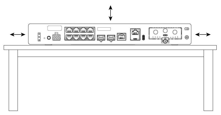
The Cisco 8200 Series Secure Router is Natural convection cooled (it has no fans) and requires clearance around the product. It should have at least 1.5” above and generally 1” around it on all sides. This applies to all mounting orientations.

Figure 1. Router cooling

Rack Requirements

For the Cisco 8200 Series Secure Routers, use 19-inch rack tray.


Note


Rack requirements is applicable only for Cisco 8200 Series Secure Routers.


The following information can help you plan your equipment rack configuration:

  • Allow clearance around the rack for maintenance.

  • The Cisco 8200 Series Secure Routers requires 2RU when installed in a rack.


    Note


    More spacing may be required depending on the installation environment.


  • Enclosed racks must have adequate ventilation. Ensure that the rack is not congested because each router generates heat. An enclosed rack should have louvered sides and a fan to provide cooling air. The heat generated by the equipment near the bottom of the rack can be drawn upward into the intake ports of the equipment above it.

Power Guidelines and Requirements

Check the power at your site to ensure that you are receiving power that is free of spikes and noise. Install a power conditioner, if necessary.

This section lists the power requirements for the Cisco 8200 Series Secure Routers.

Table 1. Power Requirements for C8231-G2

Power Source

Input Rated

Output Rated

66W AC Power Adapter

(PWR-CC1-66WAC)

100-240V, <=2A

12 VDC, 5.5A

115W AC Power Adapter

(PWR-CC1-115WAC)

100-240V, <=1.8A

12V, 4.6A, -53.5V 1.12A

Table 2. Power Requirements for C8235-G2

Power Source

Input Rated

Output Rated

66W AC Power Adapter

(PWR-CC2-66WAC)

100-240V, <=2A

12VDC, 5.5A

230W AC Power Adapter

(PWR-CC1-230WAC)

100-240V, <=3.2A

12V, 9.0A; -54V, 2.45A

Network Cabling Specifications

The following sections describe the cables and the specifications required to install Cisco 8200 Series Secure Routers:

Console Port Considerations

The router includes an asynchronous serial console port. The console ports provide access to the router using a console terminal connected to the console port. This section discusses important cabling information to consider before connecting the router to a console terminal or modem.

Console terminals send data at speeds slower than modems do; therefore, the console port is ideally suited for use with console terminals.

EIA/TIA-232

Depending on the cable and the adapter used, this port appears as a DTE or DCE device at the end of the cable. Only one port can be used at the same time.

The default parameters for the console port are 9600 baud, 8 data bits, 1 stop bit, and no parity. The console port does not support hardware flow control. For detailed information about installing a console terminal, see the Connecting to a Console Terminal or Modem section.

For cable and port pinouts, see the Cisco Modular Access Router Cable Specifications document located on Cisco.com.

USB Serial Console

The USB serial console port connects directly to the USB connector of a PC using a USB Type A to 5-pin micro USB Type-B cable. The USB Console supports full speed (12Mb/s) operation. The console port does not support hardware flow control.


Note


Always use shielded USB cables with a properly terminated shield.


USB Console OS Compatibility

  • Windows 10, Windows 8, Windows 7, Windows 2000, Window XP 32 bit, Windows Vista 32 bit

  • Mac OS X version 10.5.4

  • Redhat / Fedora Core 10 with kernel 2.6.27.5-117

  • Ubuntu 8.10 with kernel 2.6.27-11

  • Debian 5.0 with kernel 2.6

  • Suse 11.1 with kernel 2.6.27.7-9

The default parameters for the console port are 9600 baud, 8 data bits, no parity, and 1 stop bit. For detailed information about installing a console terminal, see the Connecting to a Console Terminal or Modem section on page 3-19.

For operation with a Microsoft Windows OS version older than Windows 7, the Cisco Windows USB Console Driver must be installed on any PC connected to the console port. If the driver is not installed, the prompts guide you through a simple installation process.

The Cisco Windows USB Console Driver allows plugging and unplugging the USB cable from the console port without affecting Windows HyperTerminal operations. No special drivers are needed for Mac OS X or Linux.

Only one console port can be active at a time. When a cable is plugged into the USB console port, the RJ-45 port becomes inactive. Conversely, when the USB cable is removed from the USB port, the RJ-45 port becomes active.

Baud rates for the USB console port are 1200, 2400, 4800, 9600, 19200, 38400, 57600, and 115200 bps.


Note


Only the 5-pin micro USB Type-B is supported.


Prepare for Router Installation

Before you install the Cisco 8200 Series Secure Routers, you must prepare your site for the installation. This chapter provides pre-installation information, such as recommendations and requirements that should be considered before installing your router.

See the following sections to prepare for installation:

Ethernet Connections

The IEEE has established Ethernet as standard IEEE 802.3. The routers support the following Ethernet implementations:

1000BASE-T—1000 Mb/s full-duplex transmission over a Category 5 or better unshielded twisted-pair (UTP) cable.

Supports the Ethernet maximum length of 328 feet (100 meters).

100BASE-T—100 Mb/s full-duplex transmission over a Category 5 or better unshielded twisted-pair (UTP) cable.

Supports the Ethernet maximum length of 328 feet (100 meters).

10BASE-T—10 Mb/s full-duplex transmission over a Category 5 or better unshielded twisted-pair (UTP) cable.

Supports the Ethernet maximum length of 328 feet (100 meters).

2.5GBASE-T – 2.5 Gb/s full-duplex transmission over a Category 5e or better unshielded twisted-pair (UTP) cable.

Supports the Ethernet maximum length of 328 feet (100 meters).

See the Cisco Modular Access Router Cable Specifications document at Cisco.com for information about Ethernet cables, connectors, and pinouts.

Required Tools and Equipment for Installation and Maintenance

You need the following tools and equipment to install and upgrade the router and its components:

  • An ESD-preventive cord and a wrist strap

  • A number 2 Phillips screwdriver

  • Phillips screwdrivers: small, 3/16-in. (4 to 5 mm) and medium 1/4-in. (6 to 7 mm). You might need these when you install or remove modules, and when you remove the cover (when you upgrade the memory or other components)

  • Screws that fit your rack

  • A wire crimper

  • A wire for connecting the chassis to an earth ground: AWG 14 (2 mm²) or larger wire

  • An appropriate user-supplied UL or a CSA-certified ring terminal with an inner diameter of 1/4 in. (5 to 7 mm)