External Modules
This section describes how to install external modules and FRUs in the Cisco 8200 Series Secure Routers. The information is contained in the following sections:
The documentation set for this product strives to use bias-free language. For the purposes of this documentation set, bias-free is defined as language that does not imply discrimination based on age, disability, gender, racial identity, ethnic identity, sexual orientation, socioeconomic status, and intersectionality. Exceptions may be present in the documentation due to language that is hardcoded in the user interfaces of the product software, language used based on RFP documentation, or language that is used by a referenced third-party product. Learn more about how Cisco is using Inclusive Language.
The Cisco 8200 Series Secure Routers have field-replaceable units (FRUs) that can be quickly and easily removed and replaced without having to send the entire router for repair.
This chapter describes how to install FRUs in the Cisco 8200 Series Secure Routers. The information is contained in these sections:
This section describes how to install external modules and FRUs in the Cisco 8200 Series Secure Routers. The information is contained in the following sections:
This section describes how to install and remove Small Form Pluggable (SFP) modules in the Cisco 8200 Series Secure Routers.
Only SFP modules certified by Cisco and complies with IEC 60825-1:2014 are supported on these routers. For more information, refer to SFPs Supported on Cisco 8200 Series Secure Routers.
Take note of the following optical connection warnings:
 Warning |
Statement 1051—Laser Radiation Invisible laser radiation may be emitted from disconnected fibers or connectors. Do not stare into beams or view directly with optical instruments. |
Warning |
Statement 1055—Class 1/1M Laser Invisible laser radiation is present. Do not expose to users of telescopic optics. This applies to Class 1/1M laser products.  |
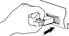
To install a SFP module in your router:
Disconnect the power supply before you replace any module.
Slide the SFP into the router connector until it locks into position.
 Note |
The following image is for reference only. |
 Caution |
Do not remove the optical port plugs from the SFP until you are ready to connect cabling. |
Connect the network cable to the SFP module.
To remove a SFP module on your router:
Disconnect the power supply and remove all cables from the SFP module.
Caution |
The latching mechanism used on many SFPs locks the SFP into place when cables are connected. Do not pull at the cabling in an attempt to remove the SFP. |
Disconnect the SFP latch.
Note |
SFP modules use various latch designs to secure the module in the SFP port. Latch designs are not linked to SFP models or technology type. For information on the SFP technology type and model, see the label on the side of the SFP. |
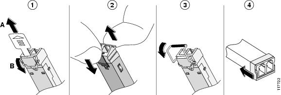
1: Sliding latch
2: Swing and slide latch
3: Bale-clasp latch
4: Plastic collar latch
Grasp the SFP on both sides and remove it from the router.
Warning |
Statement 1029—Blank Faceplates and Cover Panels Blank faceplates and cover panels serve three important functions: they reduce the risk of electric shock and fire, they contain electromagnetic interference (EMI) that might disrupt other equipment, and they direct the flow of cooling air through the chassis. Do not operate the system unless all cards, faceplates, front covers, and rear covers are in place. |
Warning |
Statement 1255—Laser Compliance Statement Pluggable optical modules comply with IEC 60825-1 Ed. 3 and 21 CFR 1040.10 and 1040.11 with or without exception for conformance with IEC 60825-1 Ed. 3 as described in Laser Notice No. 56, dated May 8, 2019. |
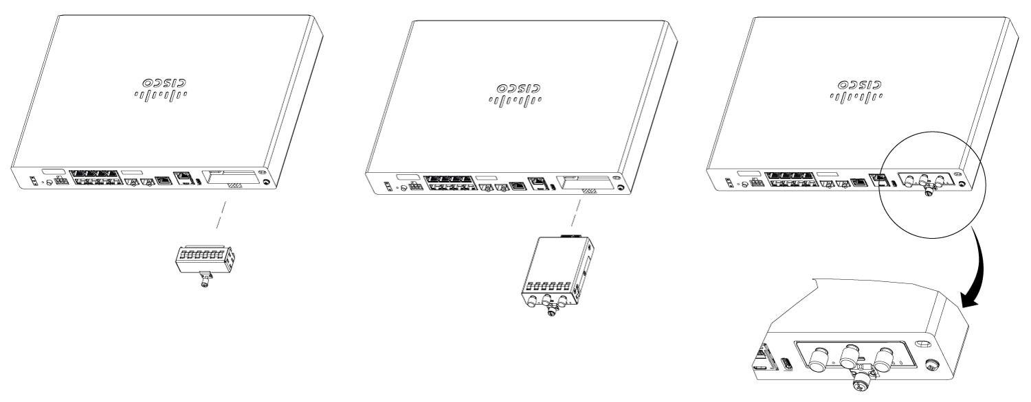
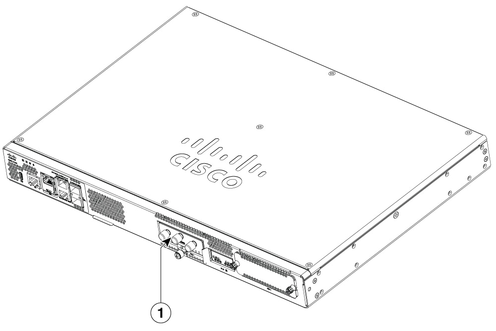
To insert the pluggable interface module into the router, follow these steps:
|
Step 1 |
Insert and then gently push the LTE pluggable into the pluggable slot until firmly fixed. |
|
Step 2 |
Tighten the screw, the recommended torque is 10-12 in-lb. |
|
1. |
Pluggable interface module (PIM) |
|
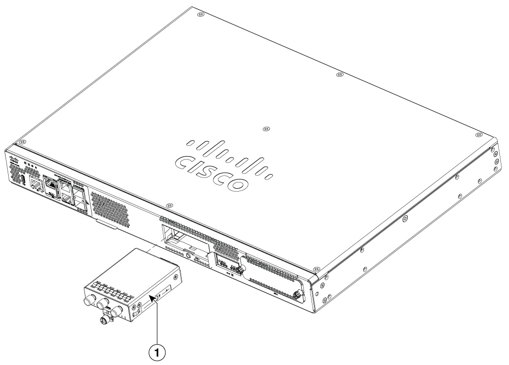
1. |
Pluggable interface module (PIM) |
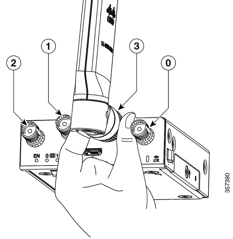
To insert the antenna in the Pluggable Interface Module, perform the following steps:
|
Step 1 |
Use your thumb and index finger to insert and tighten antenna 1 and antenna 3 in the middle antenna attachment slots, as indicated in the figure.
|
||
|
Step 2 |
Insert antenna 2 and antenna 0 in the first and last antenna attachment slots. |
||
|
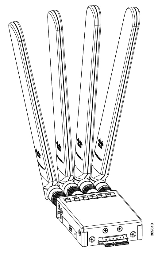
Step 3 |
After installing the antennas, adjust the antenna orientation by spacing out each of them equally until they are spread out. This is important because it helps in getting higher RF performance. |
The following table lists the RF band mapping for antenna ports.
| Radio Access Technology (RAT) |
Bands |
Tx Antennas |
Rx Antennas |
GNSS Antenna |
|||||
|---|---|---|---|---|---|---|---|---|---|
|
Default |
Alternate Path |
ANT0 |
ANT1 |
ANT2 |
ANT3 |
GPS |
|||
|
5GNR Sub-6G |
29 |
- |
- |
Y |
- |
Y |
- |
- |
|
|
38, 41 |
ANT2 |
ANT0 |
Y |
Y |
Y |
Y |
- |
||
|
48 |
ANT3 |
ANT1 |
Y |
Y |
Y |
Y |
- |
||
|
75, 76 |
- |
- |
Y |
Y |
Y |
Y |
- |
||
|
77, 78 |
ANT3 |
ANT1 ANT2 |
Y |
Y |
Y |
Y |
- |
||
|
79 |
ANT3 |
ANT1 |
Y |
Y |
Y |
Y |
- |
||
|
LB LTE/ 5GNR Sub-6G |
5, 8, 12, 13, 14, 17, 18, 19, 20, 26, 28, 71 |
ANT0 |
- |
Y |
- |
Y |
- |
- |
|
|
MB/HB LTE/ 5G NR Sub-6G |
1, 2, 3, 4, 7, 25, 30, 39, 40, 66, 70 |
ANT0 |
- |
Y |
Y |
Y |
Y |
- |
|
|
LTE |
29 |
- |
- |
Y |
- |
- |
Y |
- |
|
|
34 |
ANT0 |
- |
Y |
- |
Y |
- |
- |
||
|
46 |
- |
- |
Y |
- |
- |
Y |
- |
||
|
32 |
- |
- |
Y |
Y |
Y |
Y |
- |
||
|
38 |
ANT0 |
- |
Y |
Y |
Y |
Y |
- |
||
|
41 |
ANT0 |
ANT2 |
Y |
Y |
Y |
Y |
- |
||
|
42, 43, 48 |
ANT3 |
ANT1 |
Y |
Y |
Y |
Y |
- |
||
|
WCDMA |
1, 2, 4, 5, 8, 19 |
ANT0 |
- |
Y |
- |
Y |
- |
- |
|
|
GNSS |
- |
- |
- |
- |
- |
- |
- |
L1 |
|
The following table lists the LED indicators and their behavior. The LEDs provide a visual indication of the status and the currently selected services.
|
LED |
Color |
Function |
|---|---|---|
|
EN |
Green, Yellow |
Enable LED
|
|
SIM0 |
Green, Yellow |
SIM0 LED/Activity
|
|
SIM1 |
Green, Yellow |
SIM1 LED/Activity
|
|
GPS |
Green, Yellow |
GPS LED
|
|
RSSI |
Green, Yellow |
RSSI LED (Applicable for P-LTE-XX, P-LTEA-XX, P-LTEAP18-GL )
|
The C8231-E-G2 and C8235-E-G2 routers have removable covers. Do not attempt to run the router without the cover. This can cause the router to overheat very quickly. To remove the chassis cover, use a number-2 Phillips screwdriver and perform these tasks.
To remove the cover, perform the following steps:
|
Step 1 |
Disconnect the power supply before you perform any module replacement. |
||||||
|
Step 2 |
Confirm the router is turned off and disconnected from the power supply. |
||||||
|
Step 3 |
Disconnect all port cables so that that no one works on the unit with attached cable in the event of lightning or surges. |
||||||
|
Step 4 |
Place the chassis on a flat surface.Remove the nine cover screws from the router cover (marked in the figure). |
||||||
|
Step 5 |
Lift the cover straight up. 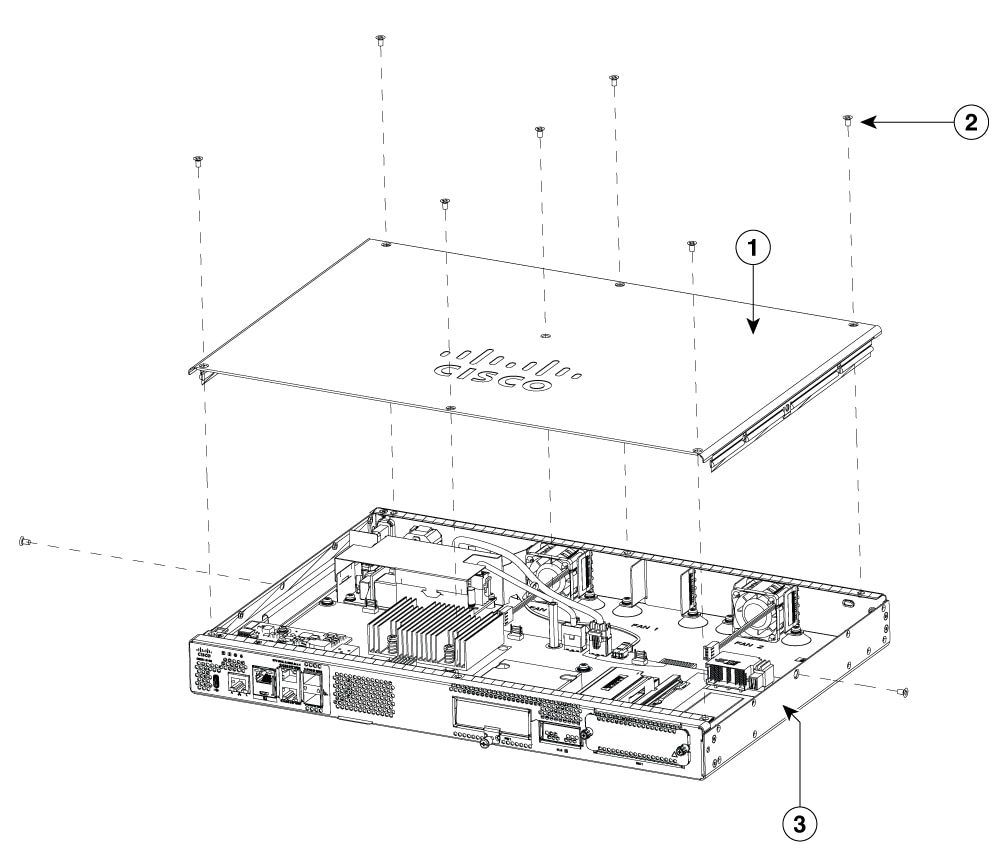
|
To replace the cover, perform the these steps:
|
Step 1 |
Disconnect the power supply before you begin replacing the chassis cover. |
|
Step 2 |
Confirm that the router is turned off and disconnected from the power supply (or power supplies) if there is redundant power supply. |
|
Step 3 |
Disconnect all port cables to ensure that no one works on the unit with attached cable in the event of lightning or surges. |
|
Step 4 |
Place the chassis on a flat surface. |
|
Step 5 |
Locate the cover hooks and secure the screws on each side. |
To remove a NVMe module, perform these steps:
|
Step 1 |
The device should be powered down and the power supply disconnected before you perform any module replacement. |
||
|
Step 2 |
Use the latch to open the module. |
||
|
Step 3 |
Gently pull the NVMe module out and remove it from the device. 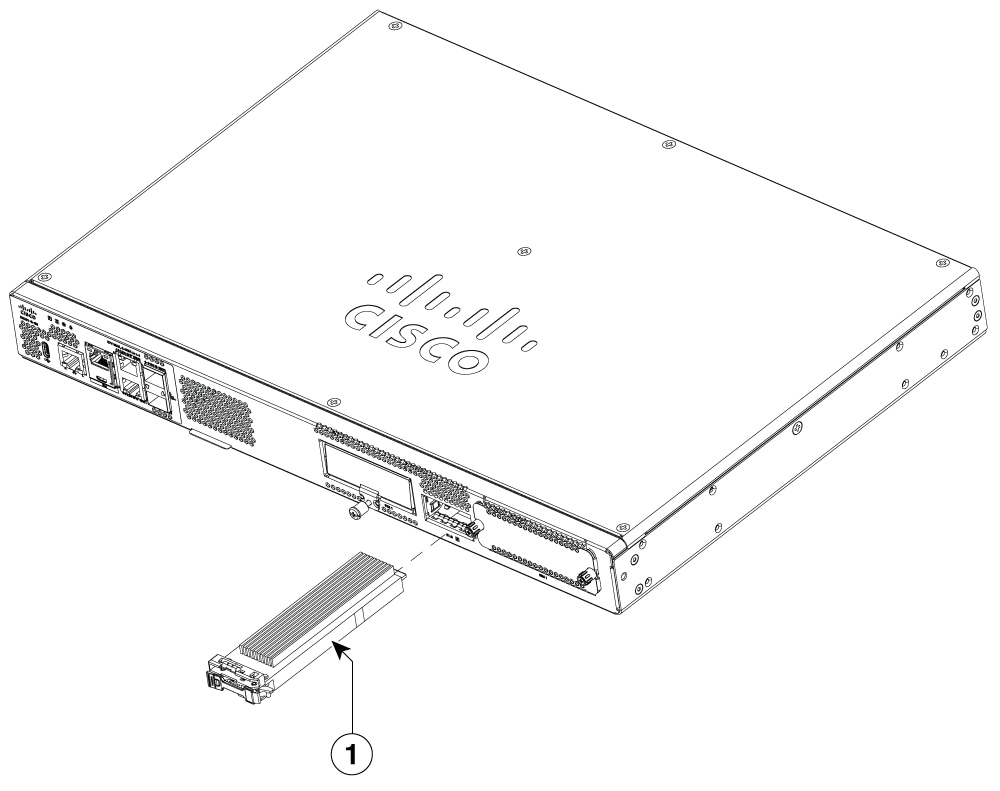
|
To install the NVMe module, perform the following steps:
|
Step 1 |
Read all Safety Warnings, ensure that the router is not powered on. |
||
|
Step 2 |
Insert the NVMe module into the slot of the device (as shown in the figure). |
||
|
Step 3 |
Gently slide the NVMe module all the way in until the faceplate is flush with the device. |
||
|
Step 4 |
Use the latch to tighten and lock the module. |
||
|
Step 5 |
The device can now be powered on. 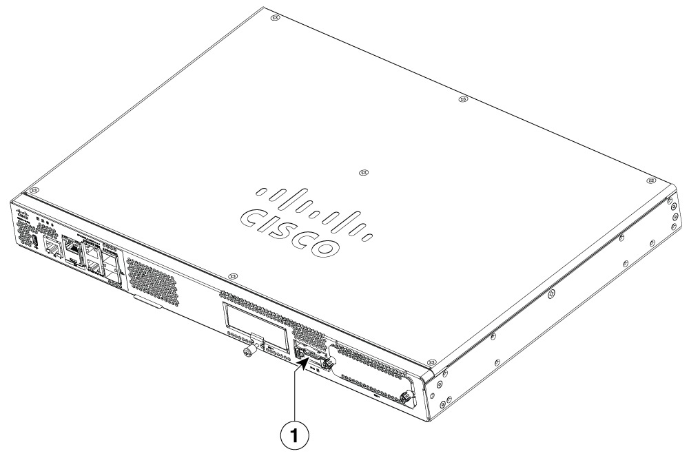
|
Keep the following tools and equipment while working with the Network Interface Modules:
Number 1 Phillips screwdriver or a small flat-blade screwdriver
ESD-preventive wrist strap
Follow these steps to remove a Network Interface Module.
|
Step 1 |
Shut down the electrical power to the slot in the device, turn off the electrical power to the device. Leave the power cable plugged-in to channel ESD voltages to ground. |
||
|
Step 2 |
Remove all network cables from the rear panel of the device. Using a number 1 Phillips screwdriver, loosen the captive screws on the network interface module. |
||
|
Step 3 |
Slide the network interface module out. |
||
|
Step 4 |
If you are not replacing the module, install a blank faceplate over the empty slot to ensure proper air flow. 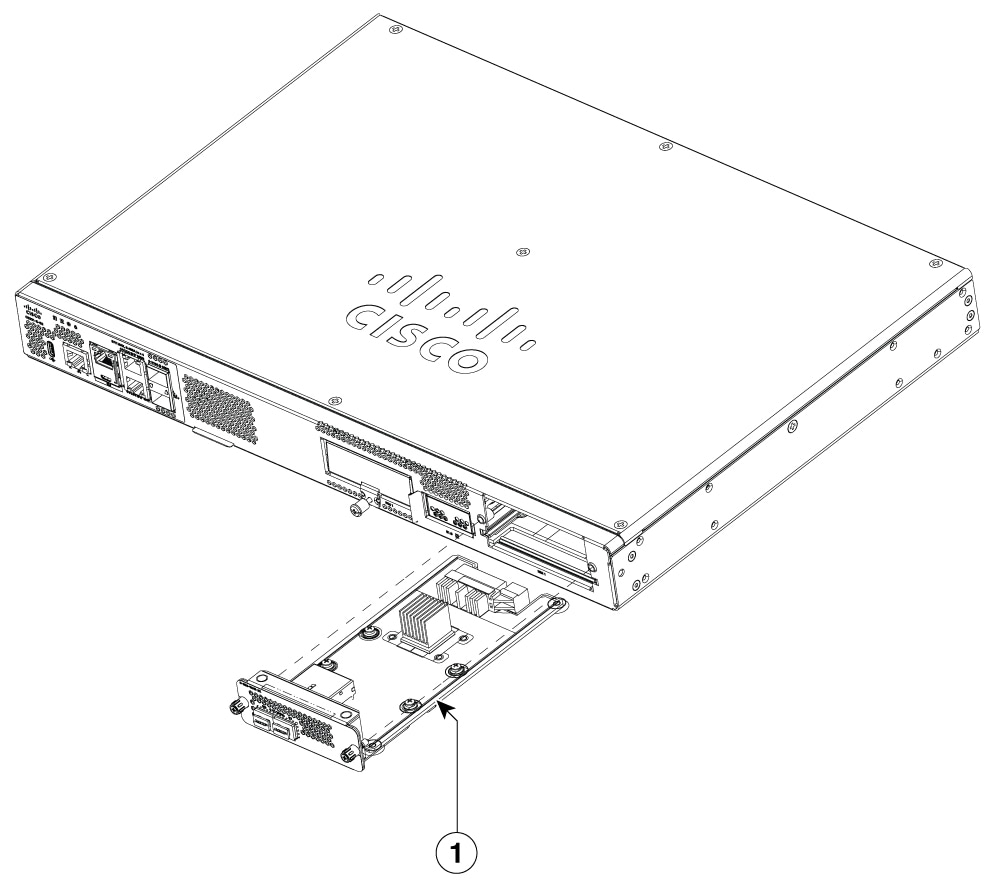
|
Follow these steps to install a Network Interface Module.
|
Step 1 |
Shut down the electrical power to the slot in the router by turning off the electrical power to the router. Leave the power cable plugged in to channel ESD voltages to ground. |
||
|
Step 2 |
Remove all network cables from the rear panel of the device. |
||
|
Step 3 |
Remove the blank faceplates installed over the network interface module slot that you intend to use.
|
||
|
Step 4 |
Align the module with the guides in the chassis walls or slot divider and slide it gently into the NIM slot on the device. |
||
|
Step 5 |
Push the module into place until you feel the edge connector seat securely into the connector on the router backplane. The module faceplate should contact the chassis rear panel. |
||
|
Step 6 |
Using a number 1 Phillips screwdriver, tighten the captive screws on the network interface module. 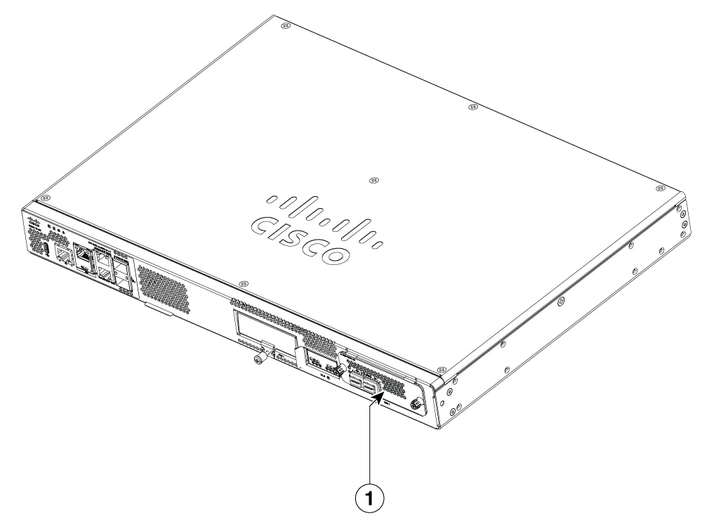
|
||
|
Step 7 |
Connect the module to the network and re-enable the power to the slot in the device. |
 Feedback