About Cisco 8200 Series Secure Routers
Designed for medium branch deployments, Cisco 8200 Series Secure Routers combine robust security, advanced performance engineering, and flexible management options. These routers offer seamless connectivity, dynamic path selection, and unified security enforcement, ensuring resilient operations and simplified IT overhead as your network grows. With integrated security and support for high-speed 10G interfaces, these platforms deliver scalable and reliable performance for modern WAN edge deployments.
|
Base Models |
WAN Ports |
Flex Ports |
Switch Ports |
Management Port |
Console Port | (Optional) POE |
USB Type C |
|---|---|---|---|---|---|---|---|
|
C8231-G2 |
2 SFP + 2 RJ-45 |
2 RJ-45 |
4 RJ-45 |
1 RJ-45 |
Serial RJ-45 |
PoE Output -53.5VDC (port 7), 0.56A, 30 W max |
5V, 1.5A max |
|
C8235-G2 |
2 SFP + 2 RJ-45 |
2 RJ-45 |
4 RJ-45 |
1 RJ-45 |
Serial RJ-45, Micro USB |
PoE output -54VDC, 555mA (Port 4-5) and 1.66A (Port 6-7) total 120W max |
5V, 1.5A max |
|
C8231-E-G2 |
2 SFP + 2 RJ-45 |
None |
None |
1 RJ-45 |
Serial RJ-45, Micro USB |
PoE output -54VDC, 1.66A total 150W max |
5V, 1.5A max |
|
C8235-E-G2 |
2 SFP + 2 RJ-45 |
None |
None |
1 RJ-45 |
Serial RJ-45, Micro USB |
PoE output -54VDC, 1.66A total 150W max |
5V, 1.5A max |
 Note |
C8231-G2 has 8GB of DRAM and 16GB of bootflash memory. C8235-G2 has 16GB of DRAM and bootflash memory. |
For more information on the features and specifications of Cisco 8200 Series Secure Routers, refer to Cisco 8200 Series Secure Routers datasheet.
Chassis Views
Note |
The compliance label is present at the bottom of the product. |
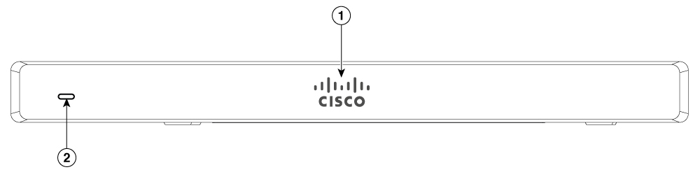
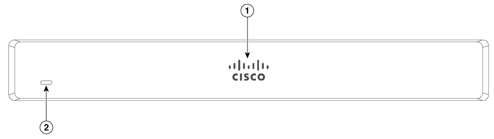
This section contains front and back panel views of the Cisco 8200 Series Secure Routers showing locations of the power and signal interfaces, interface slots, status indicators, and chassis identification labels.
|
1 |
Non-illuminated Cisco logo |
|
2 |
Status LED |
|
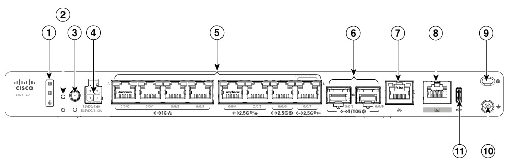
1 |
Status LEDs |
2 |
Reset button |
|
3 |
Power button |
4 |
4-pin power connector |
|
5 |
Ethernet ports (0-7) |
6 |
SFP+ ports |
|
7 |
Management port |
8 |
Console port |
|
9 |
Kensington lock slot |
10 |
Ground point |
|
11 |
USB Type C port |
|
1 |
Non-illuminated Cisco logo |
|
2 |
Status LED |
|
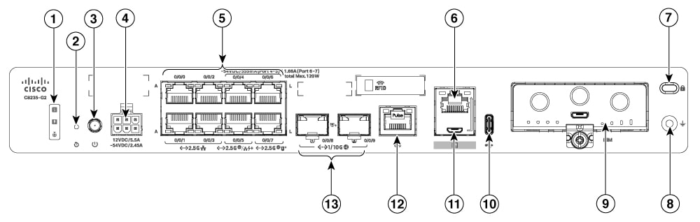
1 |
Status LEDs |
2 |
Reset button |
|
3 |
Power button |
4 |
6-pin power connector |
|
5 |
Ethernet ports |
6 |
RJ45 Console port |
|
7 |
Kensington lock slot |
8 |
Ground point |
|
9 |
Pluggable interface module (PIM) slot |
10 |
USB Type C port |
|
11 |
Micro-USB console port |
12 |
Management port |
|
13 |
SFP+ ports |
Note |
The C8231-E-G2 and C8235-E-G2 chassis look the same except for the printed PID number. |
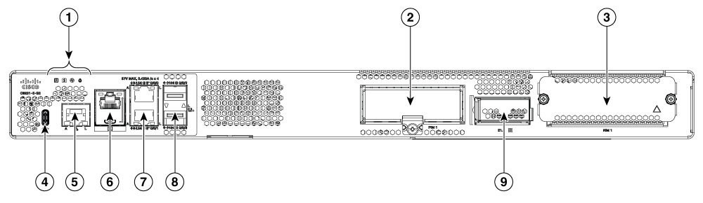
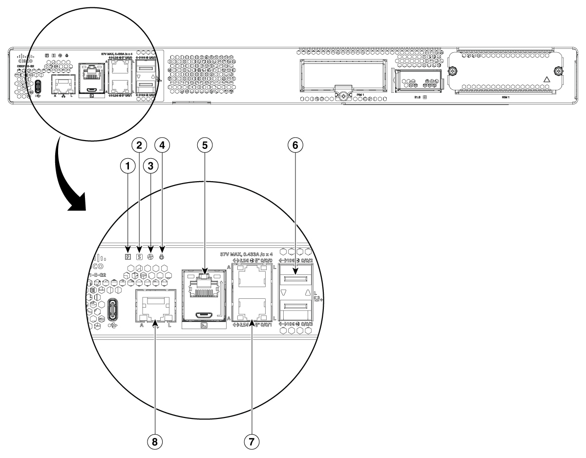
|
1 |
Status LEDs |
2 |
Pluggable interface module (PIM) Slot |
|
3 |
Service module (SM) slot |
4 |
USB Type C slot |
|
5 |
Management port |
6 |
RJ45 and Micro-USB console port |
|
7 |
Ethernet port |
8 |
SFP+ ports |
|
9 |
E1.S slot |
|
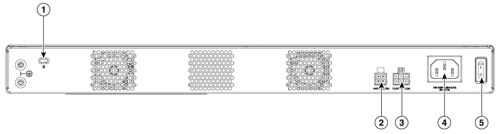
1 |
Kensington lock slot |
2 |
Optional POE power |
|
3 |
Optional redundancy power |
4 |
AC Power connector |
|
5 |
Power switch |
LED Indicators
This section summarizes the LED indicators for Cisco 8200 Series Secure Routers.
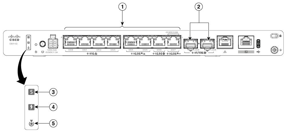
|
1 |
Ethernet ports LED(0-7) |
2 |
SFP port LED |
|
3 |
Status LED |
4 |
POE LED |
|
5 |
Blue Beacon LED |
|
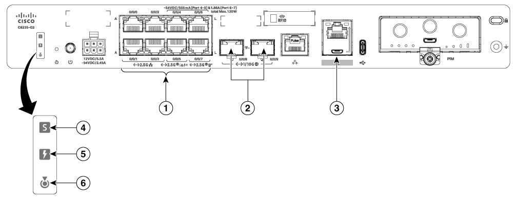
1 |
Ethernet ports LED 0-7 (0, 2, 4, 6 at the top and 1, 3, 5, 7 at the bottom) |
2 |
SFP port LED |
|
3 |
RJ-45 console LED |
4 |
Status LED |
|
5 |
POE LED |
6 |
Blue Beacon LED |
|
Port |
LED Color |
Function |
Description |
|
|---|---|---|---|---|
|
Status (1 LED) |
Tri-colour LED: Green, Amber and Red |
System power status |
Off: No power. |
|
|
Red steady on: System is booting. |
||||
|
Red blink: The system has experienced a hardware integrity error. |
||||
|
Amber steady on: Rommon has completed booting and system is a rommon prompt or booting IOS. |
||||
|
Green steady on: Normal system operation. |
||||
|
POE_OK (1 LED) |
Bi-colour LED: Green and Amber |
POE power supply status |
Off: No -53.5V POE power supply connected to router. |
|
|
Green Steady On: -53.5V POE power supply connected and all powered port operating normally |
||||
|
Amber steady on: -53.5V POE power supply connected, but one or more POE ports has a fault. |
||||
|
Ethernet Ports, without POE (2 LEDs per port) |
Green |
Activity / Link |
Left LED: Activity |
Right LED: Link |
|
Off: No data |
Off: No link |
|||
|
Green blink: Tx/Rx data |
Green steady on:Link up |
|||
|
Ethernet Ports, with POE (2 LEDs per port) |
Bi- colour LED Green and Amber |
Activity/Link/POE status |
Left LED: Activity |
Right LED: Link/POE fault |
|
Off: No data |
Off: No link |
|||
|
Green blink: Tx/Rx data |
Green steady on:Link up |
|||
|
Amber steady on:POE fault |
||||
|
Console port RJ45 port/Micro USB console (1 LED) |
Green |
Console or AUX port function for RJ45/USB mode |
Left LED: Integrated RJ45 Console or AUX port function enabled Off: USB console mode Green on: Console enabled |
Right LED: Integrated RJ45 USB Mode Active Off:RJ45 Console /AUX Mode or nothing is connected Green On: USB mode |
|
Blue beacon |
Blue |
Unit rack location |
Off: Beacon not activated On: Beacon activated |
|
|
SFP Port 1 LED per port |
Bi- colour LED Green and Amber |
Link/Fault |
Off: No link (or SFP not present) Green: Link up Amber: The SFP is not supported or it is in a fault state |
|
|
1 |
Power LED |
2 |
Status LED |
|
3 |
Enviormental LED |
4 |
Blue Beacon |
|
5 |
RJ45/USB console LED |
6 |
SFP Port |
|
7 |
Ethernet Port LED |
8 |
Management Port LED |
|
LED |
Color |
Description |
|---|---|---|
|
PWR |
Green/Amber |
Power Supply Status Off: The system is powered off Amber: A Power Supply in the system is not functioning correctly Green: All installed PSUs are operating correctly |
|
STATUS |
Green/Amber/Red |
System Status Blinking Amber: The system is booting Blinking Red: The system has failed a hardware integrity error Amber: Rommon has completed booting and system is at Rommon prompt or booting platform software Green: Normal System Operation |
|
ENV |
Green/Amber/Red |
Environmental Status Off: Monitor is not active Red: The system has detected a critical overcurrent event and may shut down Blinking Amber: One or more temperature sensors in the system are outside the acceptable range Amber: One or more fans in the system are outside the acceptable range Green: All temperature sensors and fans in the system are within acceptable range |
|
BEACON |
Blue |
Off: System is normal Blinking Blue: Beacon purpose |
|
USB CON |
Green |
USB Console Active Green indicates that the active console port is USB |
|
RJ-45 CON |
Green |
Serial Console Active Green indicates that RJ-45 is the active console port |
|
RJ-45 Ethernet Ports A (Active) |
Green |
Activity status Off: No data Blinking Green: Tx/Rx data |
|
RJ-45 Ethernet Ports L (Link) |
Green/Amber |
Link status Off: No data Green: Link up Amber: POE power fault and link is down |
|
SFP Ports L (Link) |
Green/Amber |
SFP port 0/1 Link LED Off: No Link (or SFP not present) Green: Link established Amber: The SFP is not supported, or it is in a fault state |
Reset Button
Note |
Reset button is available only on C8231-G2 and C8235-G2 routers. |
The actuation of the Reset button is only recognized during ROMmon boot, that is, as the router comes to the ROMmon prompt.
The Reset button does not require much force to be pressed. The Reset button should be pressed only with a small implement such as the tip of a pen or a paper clip. When the Reset button is pressed at startup, the system LED turns green.
For more information, see the Reset Overview section of the Cisco 8200 Series Secure Routers Software Configuration Guide.
Power Supply
Cisco 8200 Series Secure Routers support PoE and PoE+ power to endpoints. The product power specifications are as follows:
Power specifications for C8231-G2
-
AC input voltage: Universal 100 to 240 VAC
-
Frequency: 50 to 60 Hz
-
Output voltage: +12VDC for system power and -53.5VDC for PoE power
-
Optional PoE and PoE+ port output power: -53.5VDC, 0.56A (Port 7)
-
Maximum POE port combined output power: 30W, -53.5VDC, 0.56A (Port 7)
Power specifications for C8235-G2
-
AC input voltage: Universal 100 to 240 VAC
-
Frequency: 50 to 60 Hz
-
Output voltage: +12VDC for system power and -54VDC for PoE power
-
Optional PoE and PoE+ port output power: -54VDC, 555mA (Port 4-5) and 1.66A (Port 6-7)
-
Maximum POE port combined output power: 120W
Note |
The PoE daughter card on the C8235-G2 is included only when a PoE power supply (PSU) is selected at the time of the initial order. The PoE-DC is not field-upgradeable |
Power specifications for C8231-E-G2 and C8235-E-G2
-
AC input voltage: Universal 100 to 240 VAC
-
Frequency: 50 to 60 Hz
-
Output voltage: +12VDC for system power and -54DC for PoE power
-
Optional PoE and PoE+ port output power: -54VDC, 1.66A, total 150W max
-
Maximum POE port combined output power: 150W
Specifications of Cisco 8200 Series Secure Routers
For specifications on the Cisco 8200 Series Secure Routers, see the Cisco 8200 Series Secure Routers' datasheet.
 Feedback