Install a Pluggable Interface Module
Before you begin
 Warning |
Statement 1255—Laser Compliance Statement Pluggable optical modules comply with IEC 60825-1 Ed. 3 and 21 CFR 1040.10 and 1040.11 with or without exception for conformance with IEC 60825-1 Ed. 3 as described in Laser Notice No. 56, dated May 8, 2019. |
Procedure
|
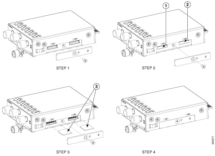
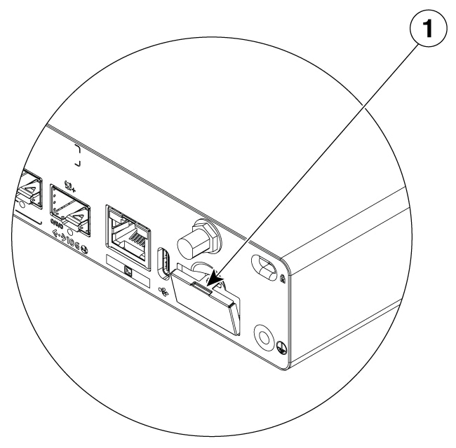
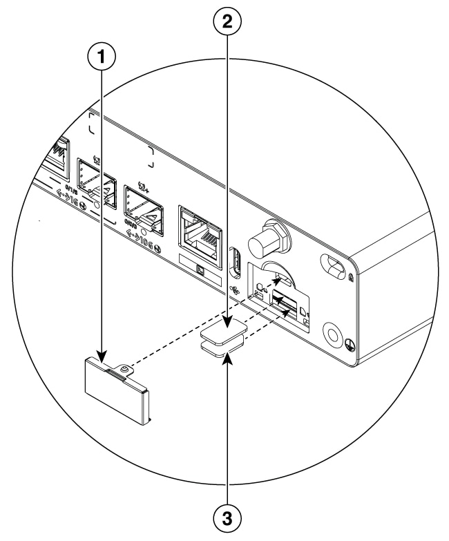
Step 1 |
Insert and then gently push the Cellular pluggable into the pluggable slot of C8151-G2 or C8161-G2 until firmly fixed. Example: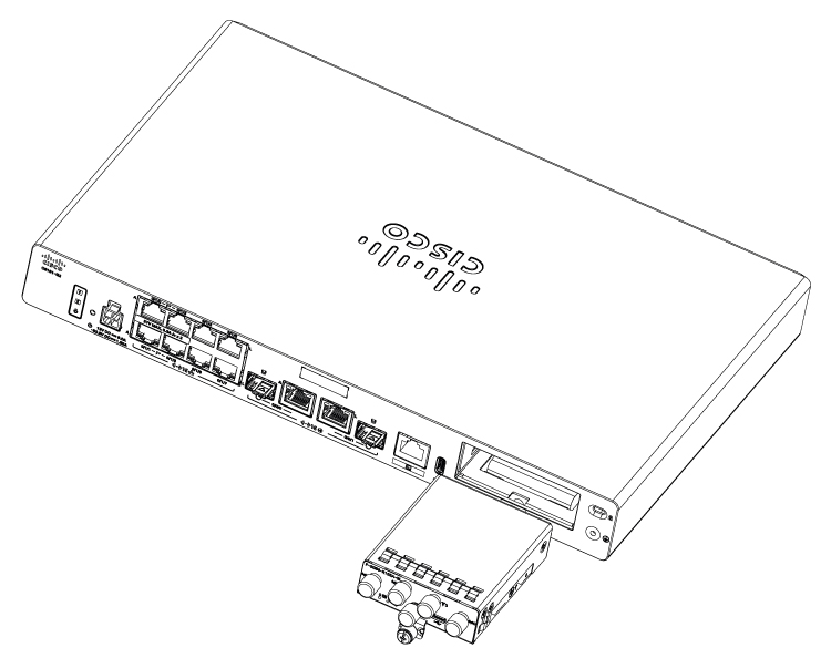
|
||||||||||||||||||||||||||||||||||||||||||||||||||||||||||||||||||||||||||||||||||||||||||||||||||||||||
|
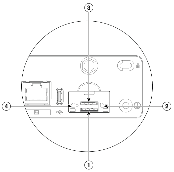
Step 2 |
Tighten the screw, the recommended torque is 10-12 in-lb. Example: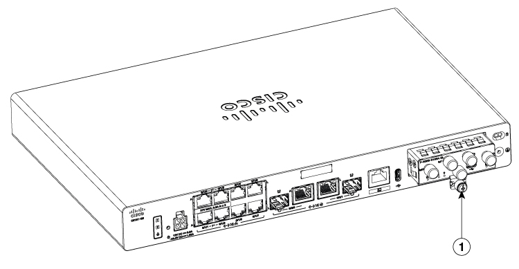

|
 Feedback