Cisco 8100 Series Secure Routers
The Cisco 8100 Series Secure Routers are the next generation, IOS XE based, multi-core, branch routers. These platforms are fixed with some pluggable cellular options.
|
Base Models |
LAN Ports Only |
WAN Ports Only |
Flex L2/L3 Ports |
Console Ports |
Power Supply |
DRAM, Flash |
Storage |
PoE/PoE+ |
Cellular Connectivity |
|---|---|---|---|---|---|---|---|---|---|
|
C8130-G2 |
2xGE RJ45 |
1xGE RJ45 1xGE RJ45/SFP combo |
2xGE RJ45 |
1xRJ45 console |
30W/66W |
4 GB, 16 GB |
USB Type C 3.0 |
None |
None |
|
C8131-G2 |
2xGE RJ45 |
1xGE RJ45 1xGE RJ45/SFP combo |
2xGE RJ45 |
1xRJ45 console |
30W/66W |
8 GB, 16 GB |
USB Type C 3.0 |
None |
None |
|
C8140-G2 |
6xGE RJ45 |
2xGE RJ45/SFP combo |
2xGE RJ45 |
1xRJ45 console |
66W |
4 GB, 16 GB |
USB Type C 3.0 |
None |
None |
|
C8151-G2 |
6xGE RJ45 |
2xGE RJ45/SFP combo |
2xGE RJ45 |
1xRJ45 console |
66W |
8 GB, 16 GB |
USB Type C 3.0 |
None |
5G Standalone/CAT 7 LTE (Pluggable) |
|
C8161-G2 |
6xGE RJ45 |
2xGE RJ45/SFP combo |
2xGE RJ45 |
1xRJ45 console |
150W |
8 GB, 16 GB |
USB Type C 3.0 |
4PoE/2PoE+ |
5G Standalone/CAT 7 LTE (Pluggable) |
|
C8130-VAI-G2 |
2xGE RJ45 |
RJ11 DSL, 1xGE RJ45/SFP combo, XGSPON/10GBASE-T |
2xGE RJ45 |
1xRJ45 console |
66W |
4GB, 16GB |
USB Type-C 3.0 |
None |
None |
|
C8130-VAP-G2 |
2xGE RJ45 |
RJ11 DSL, 1xGE RJ45/SFP combo, XGSPON/10GBASE-T |
2xGE RJ45 |
1xRJ45 console |
66W |
4GB, 16GB |
USB Type-C 3.0 |
None |
None |
|
C8151-CVAI-G2 |
6xGE RJ45 |
RJ11 DSL, 1xGE RJ45/SFP combo, XGSPON/10GBASE-T |
2xGE RJ45 |
1xRJ45 console |
66W |
8GB, 16GB |
USB Type-C 3.0 |
None |
Embedded 5G Release-17 |
|
C8151-CVAP-G2 |
6xGE RJ45 |
RJ11 DSL, 1xGE RJ45/SFP combo, XGSPON/10GBASE-T |
2xGE RJ45 |
1xRJ45 console |
66W |
8GB, 16GB |
USB Type-C 3.0 |
None |
Embedded 5G Release-17 |
|
Base Models |
5G NR Sub-6 Frequency Bands |
4G LTE Frequency Bands |
|---|---|---|
|
C8151-CVAI-G2 C8151-CVAP-G2 |
1, 2, 3, 5, 7, 8, 12, 13, 14, 18, 20, 25, 26, 28, 30, 38, 40, 41, 48, 66, 70, 71, 77, 78, 79 |
1, 2, 3, 4, 5, 7, 8, 12, 13, 14, 17, 18, 19, 20, 25, 26, 28, 30, 34, 38, 39, 40, 41, 42, 43, 48, 66, 70, 71, 106 |
|
P-5GS6-R16SA-GL |
1, 2, 3, 5, 7, 8, 12, 13, 14, 18, 20, 25, 26, 28, 29, 30, 38, 39, 40, 41, 48, 66, 70, 71, 75, 76, 77, 78, 79 |
1, 2, 3, 4, 5, 7, 8, 12, 13, 14, 18, 19, 20, 21, 25, 26, 28, 29, 30, 32, 34, 38, 39, 40, 41, 42, 43, 46, 48, 66, 71 |
|
Pluggable Interface Modules (PIM) |
Pluggable Interface Modules (PIM) Technology |
|---|---|
|
P-5GS6-R16SA-GL |
5G Sub-6 GHz Pluggable Interface Module |
|
P-LTEA7-NA |
CAT7 LTE Pluggable for North America |
|
P-LTEA7-JP |
CAT7 LTE Advanced PIM for Japan |
|
P-LTEA7-EAL |
CAT7 LTE Advanced PIM for EMEA, APAC, LATAM |
Chassis views
|
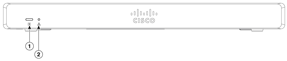
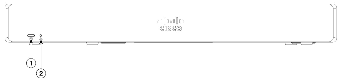
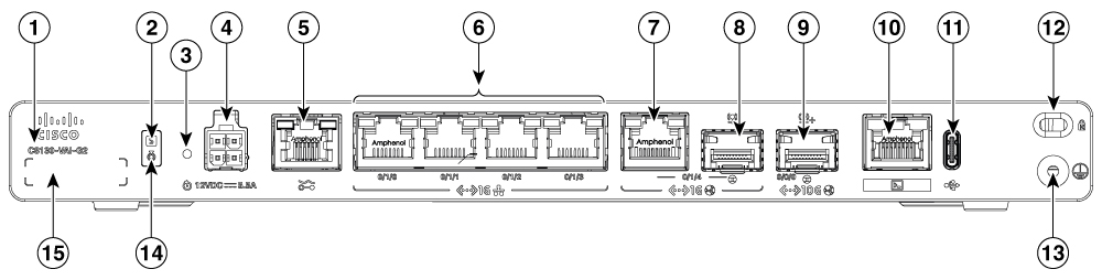
1 |
System status |
2 |
VPN |
|
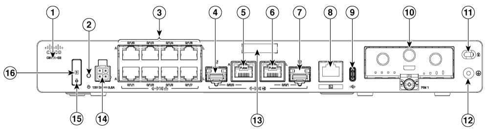
1 |
Product Identification Number (PID) |
2 |
System status |
|
3 |
Reset button |
4 |
4-Pin power connector |
|
5 |
GE RJ45 0/1/0 to 0/1/3 |
6 |
GE 0/0/0 - RJ45 |
|
7 |
GE 0/0/1 - RJ45 |
8 |
RJ45 console port |
|
9 |
USB-C 3.0 |
10 |
Kensington lock slot |
|
11 |
Grounding |
12 |
GE 0/0/1 - SFP |
|
13 |
Blue beacon |
14 |
Serial number |
|
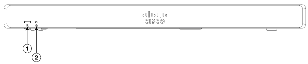
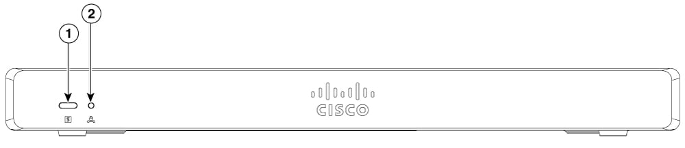
1 |
System status |
2 |
VPN |
|
1 |
Product Identification Number (PID) |
2 |
System status |
|
3 |
Reset button |
4 |
4-Pin power connector |
|
5 |
GE RJ45 0/1/0 to 0/1/3 |
6 |
GE 0/0/0 - RJ45 |
|
7 |
GE 0/0/1 - RJ45 |
8 |
RJ45 console port |
|
9 |
USB-C 3.0 |
10 |
Kensington lock slot |
|
11 |
Grounding |
12 |
GE 0/0/1 - SFP |
|
13 |
Blue beacon |
14 |
Serial number |
|
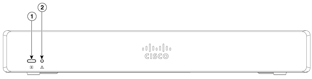
1 |
System status |
2 |
VPN |
|
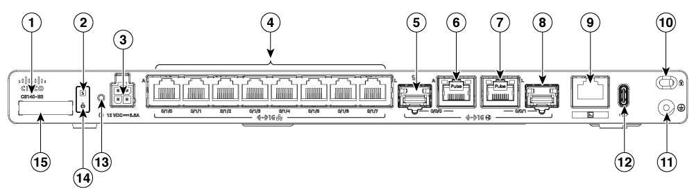
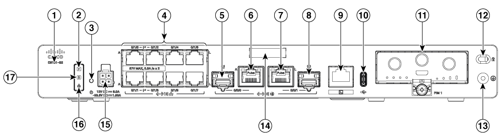
1 |
Product Identification Number (PID) |
2 |
System status |
|
3 |
4-Pin power connector |
4 |
GE RJ45 0/1/0 to 0/1/7 |
|
5 |
GE 0/0/0 - SFP |
6 |
GE 0/0/0 - RJ45 |
|
7 |
GE 0/0/1 - RJ45 |
8 |
GE 0/0/1 - SFP |
|
9 |
RJ45 console port |
10 |
Kensington lock slot |
|
11 |
Grounding |
12 |
USB-C 3.0 |
|
13 |
Reset button |
14 |
Blue beacon |
|
15 |
Serial number |
|
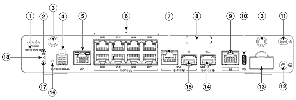
1 |
System status |
2 |
VPN |
|
1 |
Product Identification Number (PID) |
2 |
Reset button |
|
3 |
GE RJ45 0/1/0 to 0/1/7 |
4 |
GE 0/0/0 - SFP |
|
5 |
GE 0/0/0 - RJ45 |
6 |
GE 0/0/1 - RJ45 |
|
7 |
GE 0/0/1 - SFP |
8 |
RJ45 console port |
|
9 |
USB-C 3.0 |
10 |
PIM module |
|
11 |
Kensington lock slot |
12 |
Grounding |
|
13 |
Serial number |
14 |
4-Pin power connector |
|
15 |
Blue beacon |
16 |
System status |
|
1 |
System status |
2 |
VPN |
|
1 |
Product Identification Number (PID) |
2 |
POE PSU status LED |
|
3 |
Reset button |
4 |
GE RJ45 0/1/0 to 0/1/7 |
|
5 |
GE 0/0/0 - SFP |
6 |
GE 0/0/0 - RJ45 |
|
7 |
GE 0/0/1 - RJ45 |
8 |
GE 0/0/1 - SFP |
|
9 |
RJ45 console port |
10 |
USB-C 3.0 |
|
11 |
PIM module |
12 |
Kensington lock slot |
|
13 |
Grounding |
14 |
Serial number |
|
15 |
4-Pin power connector |
16 |
Blue beacon |
|
17 |
System status |
|
1 |
System status |
2 |
VPN |
|
1 |
Product Identification Number (PID) |
2 |
System status |
|
3 |
Reset button |
4 |
4-Pin power connector |
|
5 |
RJ11 DSL Port |
6 |
GE RJ45 0/1/0 to 0/1/3 |
|
7 |
GE 0/1/4 - RJ45 |
8 |
GE 0/1/4 - SFP |
|
9 |
TE 0/0/0 - XGSPON/10GBASE-T |
10 |
RJ45 console port |
|
11 |
USB-C 3.0 |
12 |
Kensington lock slot |
|
13 |
Grounding |
14 |
Blue beacon |
|
15 |
Serial number |
|
1 |
System status |
2 |
VPN |
|
1 |
Product Identification Number (PID) |
2 |
5G LED Indicator |
|
3 |
Antenna SMA connector |
4 |
4-Pin power connector |
|
5 |
RJ11 DSL Port |
6 |
GE RJ45 0/1/0 to 0/1/7 |
|
7 |
GE 0/1/8 - RJ45 |
8 |
Serial number |
|
9 |
RJ45 console port |
10 |
USB-C 3.0 |
|
11 |
Kensington lock slot |
12 |
Grounding |
|
13 |
Dual nano SIM card slot |
14 |
TE 0/0/0 - XGSPON/10GBASE-T |
|
15 |
GE 0/1/8 - SFP |
16 |
Reset button |
|
17 |
Blue beacon |
18 |
System status |
Power supply
The product power specifications are specified below:
-
AC input voltage: Universal 100 to 240 VAC
-
Frequency: 50 to 60 Hz
-
Maximum output power: Up to 30W/66W for non-PoE supply and up to 150W for PoE supply.
-
PoE and PoE+ (only for C8161-G2)
-
Output voltage: +12V for system power and -53.5V for PoE power.
|
Device supported |
Power source |
Input rated |
Output rated |
|---|---|---|---|
|
C8130-G2 C8131-G2 |
30W AC Power Adapter (PWR-CC1-30W) |
100-240VAC, 1A |
12V, 2.5A |
|
C8130-G2 C8131-G2 C8140-G2 C8151-G2 C8130-VAI-G2 C8130-VAP-G2 C8151-CVAI-G2 C8151-CVAP-G2 |
66W AC Power Adapter (PWR-CC1-66W) |
100-240VAC, 2A |
12V, 5.5A |
|
C8161-G2 |
150W AC Power Adapter (PWR-150W-AC) |
100-240 VAC, 2.5A |
12V 6.0A, -53.5V 1.55A |
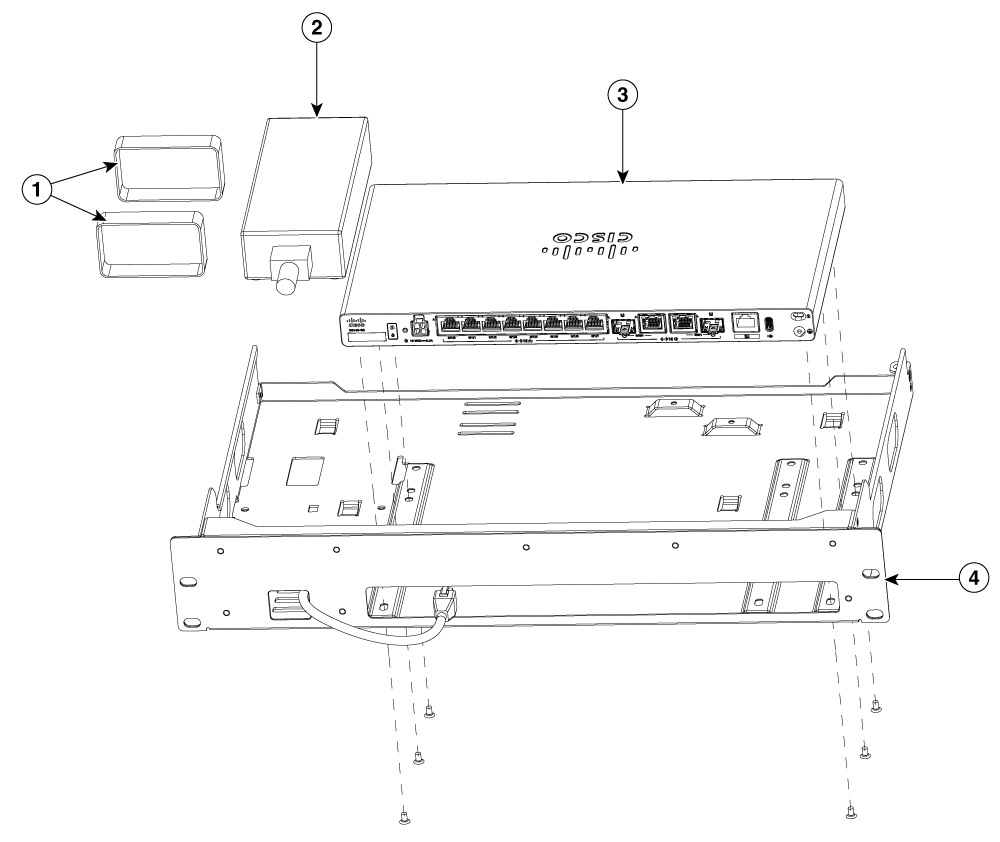
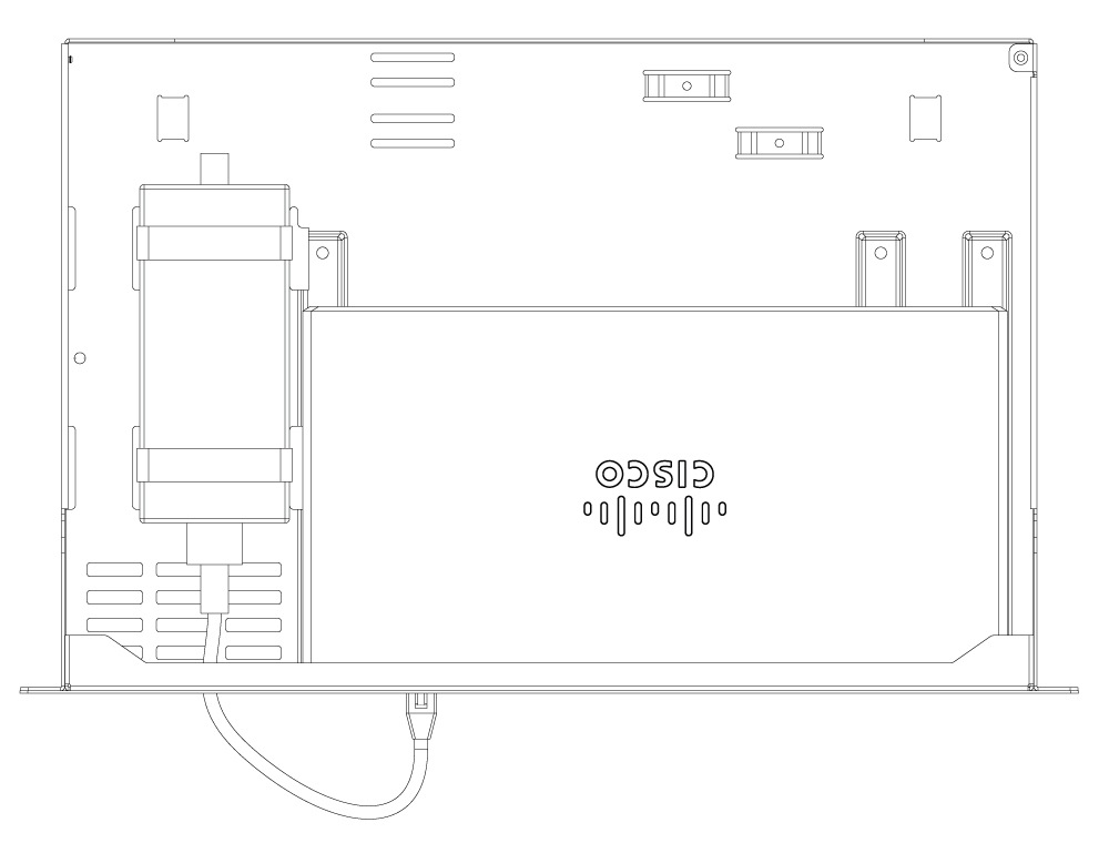
Install the router with a PSU on an Rack-tray
-
Obtain the rack-tray.
-
Align the router with the mounting holes on the rack-tray as shown in the below figure.
-
Secure the router to the tray using the provided screws.
-
Attach the velcro straps to the Power Supply Unit (PSU).
-
Secure the PSU alongside the router using the velcro straps.
-
Connect the PSU to the router using the power cable.
|
1 |
Velcro straps |
|
2 |
PSU |
|
3 |
Router |
|
4 |
Rack-tray |
LED indicators for PIM
The following table summarizes the LED indicators that are located in the Rear or chassis of the Cisco 8100 Series Secure Routers.
|
Port |
LED color |
Description |
|---|---|---|
|
System status (Front and Rear) |
Green and Amber |
Off—No power. |
|
Steady Green - System is operating normally. |
||
|
Blinking Amber — BIOS/ROMmon is booting. |
||
|
Steady Amber — BIOS/ROMmon has completed booting, and the system is at the ROMmon prompt or booting the platform software. |
||
|
VPN |
Green |
Off— No tunnel. |
|
Steady Green— At least one tunnel is up. |
||
|
Activity (WAN and LAN ports) |
Green |
Off— No data transmission. |
|
Blinking Green - TXD/RXD data. |
||
|
Link, non-PoE (WAN and LAN ports) |
Green |
Off— No link. |
|
Steady Green— Link up. |
||
|
Link, with PoE (WAN and LAN ports, C8161-G2 only) |
Green |
Off— No link, PoE administratively down. |
|
Steady Green— link up; if PoE device, power is enabled. |
||
|
Power over Ethernet (PoE/PoE+) |
Green |
Off — No -53.5V PoE power supply connected to router. |
|
Steady Green— -53.5V PoE power supply connected and all powered ports operating normally. |
||
|
Blue beacon |
Blue |
Off — No attention needed. |
|
Blinking Blue— Beacon active. |
||
|
Port |
Colour and Description |
|---|---|
|
5G LED |
Blank - No service Steady Green- 4G Steady Blue- 5G |
Reset button
The actuation of the Reset button is only recognized during ROMmon boot, that is, as the router comes to the ROMmon prompt.
The Reset button does not require much force to be pressed. The Reset button should be pressed only with a small implement such as the tip of a pen or a paper clip. When the Reset button is pressed at startup, the system LED turns green.
Slots and interfaces
The Cisco 8100 Series Secure Routers designates its interfaces using a 3-tuple notation that lists the slot, sub-slot, and port in the format slot/sub-slot/port. The slot number is reserved for the motherboard, which is "0". Each interface type is allocated a sub-slot and the port number is a unique port on the interface.
|
Sub-slot 0/x/x |
Interface type |
|---|---|
|
0 |
Ethernet WAN |
|
1 |
Ethernet LAN |
|
2 |
DSL or Cellular |
|
3 |
Cellular |
 Note |
The following interfaces located in Sub-slot 0/1 also function as WAN Combo ports:
|
Periodic inspection and cleaning
We recommend that you periodically inspect and clean the external surface of the router. Removing is recommended to minimize the negative impact of environmental dust or debris. The frequency of inspection and cleaning is dependent upon the severity of the environmental conditions, but we recommend cleaning the router once every six months.
Note |
Sites with ambient temperatures consistently above 25°C or 77°F and with potentially high levels of dust or debris might require periodic preventative maintenance cleaning. |
 Feedback