The documentation set for this product strives to use bias-free language. For the purposes of this documentation set, bias-free is defined as language that does not imply discrimination based on age, disability, gender, racial identity, ethnic identity, sexual orientation, socioeconomic status, and intersectionality. Exceptions may be present in the documentation due to language that is hardcoded in the user interfaces of the product software, language used based on RFP documentation, or language that is used by a referenced third-party product. Learn more about how Cisco is using Inclusive Language.
The vEdge 1000 router delivers highly secure site-to-site data connectivity to large enterprises. The vEdge 1000 router is
a fixed-port-configuration router with the following features:
1RU, half rack width, standard rack mountable with up to two units side by side in a 19-inch rack
100-Mbps of unidirectional Internet Mix (IMIX) forwarding traffic (inclusive of encryption)
Secure identification chip for anti-counterfeit and secure authentication
Dual power supplies with two external AC power adapters
Hardware capable of supporting 3G/4G interfaces via USB ports
Front to back cooling
Chassis Views
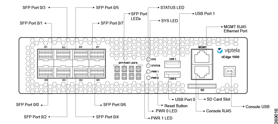
The following figures show the front and back panels of the vEdge 1000 router, indicating the location of the power interfaces,
status indicators, and chassis identification labels.
Figure 1. Front Panel of the vEdge 1000 Router
Figure 2. Back Panel of the vEdge 1000 Router
Declaration of Conformity
The Viptela products are controlled under the Commerce Control List (CCL) of the U.S. Export Administration Regulations (EAR)
as networking equipment within the following U.S. Export Control Classification Numbers (ECCN): 5A002, 5D002, and 5E002.
The vEdge hardware and software products and the Viptela encryption technology can be delivered to most end users and destinations
worldwide without a licensing requirement. The Viptela solution and products have undergone a one-time review by the Government
of the United States of America and qualify for License Exception ENC. As such, they are eligible for export according to
Section 740.17 of the EAR.
The Viptela solutions and products can be delivered to most end users worldwide, except to entities or end users in the following
countries: Cuba, Iran, North Korea, Sudan, and Syria.
Controlled Technologies
Viptela manages technology subject to the U.S. Export Administration Regulations (EAR). These controlled technologies may
include items under U.S. ECCN 5E002 encryption technology. The Viptela encryption technology is for the development, production,
and use of Viptela products that implement or use encryption.
The Viptela software distribution policy allows only authenticated users to download the Viptela encryption software. Recipients of
controlled technology are obliged to maintain adequate controls to prevent nationals from outside the U.S. and Canada from
accessing Viptela information, subject to ECCN5E002, without first obtaining authorization from the U.S. government.
For additional information on controlled technologies, please contact Viptela support at support@viptela.com .
Components and Specifications
This article provides the chassis specifications of the vEdge 1000 router and lists the other router components.
Chassis Specifications
The following table lists the specifications for the vEdge 1000 router chassis.
Chassis revisions D2 or later (including G revisions): 4 GB
Note
Characters in the serial number indicate the chassis revision.
Example of a revision D2 serial number: 11OD211111111
SD card slot (external)
Maximum capacity supported 32 GB
NAND storage (internal)
8 GB
External USB flash memory slots (Type A USB 3.0)
2
USB console port (Type B default 115.2 Kbps)
1
Serial console port (RJ-45 default 115.2 Kbps)
1
Management Ethernet port (RJ-45 10/100/1000 Mbps)
1
Power supply option
External AC-DC power adapter
Redundant power supply support
Yes
Power Specifications
AC input voltage
90-264 Vrms
AC input line frequency
47-63 Hz
Typical power consumption
28 Watts
Physical Specifications
Chassis height
1.75 in. (4.4 cm)
Chassis width
7.5 in. (19 cm)
Chassis depth
10 in. (25.4 cm)
Rack height
1 RU
Chassis weight
3.55 lb (1.6 kg)
Airflow
Front to back
Rack-mount accessory kit 19 in (48.3 cm) EIA
Available and sold separately
Packaging Specifications
Package height
8.5 in. (21.6 cm)
Package width
11.75 in. (29.84 cm)
Package depth
16.5 in. (41.9 cm)
Operating Condition
Temperature
0 to 40°C (32 to 104°F) at sea level ( temperature de-rating of 1.5 deg C per 1000 feet of altitude applicable up to max
of 10000 feet or 3000 m)
Altitude
Max 3000 m (10000 ft)
Humidity
10 to 85% RH
Transportation/Storage Condition
Temperature
-40 to 70°C (-40 to 158°F)
Humidity
5 to 95%RH
Altitude
4570 m (15000 ft)
Reliability
MTBF
80K hours
Regulatory Compliance
Safety
AS/NZS 60950-1 CAN/CSA 60950-1 CB-IEC60950-1 CE Marking EN 60950-1 UL60950-1
EMC
AS/NZS CISPR22 Class A EN 300 386 EN 55022 Class A FCC Class A ICES Class A VCCI Class A
Environmental
ROHS 6/6
Rack-Mount Tray Specifications
The following table lists the specifications for the rack-mount tray. You can use the rack-mount tray to install the vEdge
1000 router if you want to install two vEdge routers in the same slot in a 19-inch rack or if you want to mount the router
on all four posts of the rack. See Install the vEdge 1000 Router .
Table 2.
Item
Specification
Height
18.9 in. (48 cm)
Width
1.75 in. (4.45 cm)
Depth
22.36 in. (56.8 cm) including the cable management ears
Front Panel Components
This article describes the LEDs, reset button, and the SD card slot on the front panel of the vEdge 1000 router. See Chassis
Views for the location of all components on the front panel of the router.
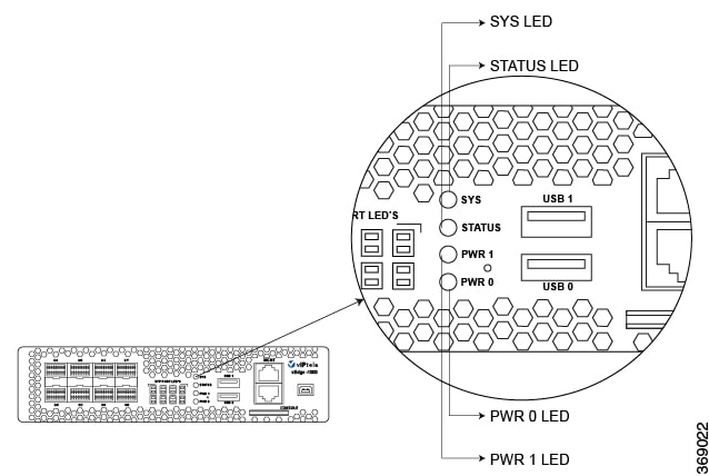
LEDs
The vEdge 1000 router has four chassis status LEDs located in the center of the front panel next to the USB ports.
Figure 3. Chassis Status LEDs in a vEdge 1000 Router
The following table describes the LEDs , their color and states, and the status they indicate.
Table 3.
LED
Color
Status
SYS
Green/Red
Off: System is not on
Green: System is healthy and operating fine
Blinking Green: System is booting up
Red: One of the daemons has failed
STATUS
Green
Off: OMP is down
Green: OMP with vSmart is up
PWR 0
Green/Red
Off: Power adapter input 0 is unpowered
Green: 12-Volt output is OK on power input 0
Red: Fault on power input 0
PWR 1
Green/Red
Off: Power adapter input 1 is unpowered
Green: 12-Volt output is OK on power input 1
Red: Fault on power input 1
Reset Button
The front panel of the vEdge router has a Reset button. The Reset button is recessed to avoid accidentally pressing it while
the router is operational. To press the Reset button, use a sharp narrow tool. The following table describes the effects of
pressing the Reset button.
Table 4.
Press Duration
Behavior
Short press
Pressing for two seconds resets and reboots the router.
Long press
Pressing for 10 seconds resets the router and reboots it with factory default configuration.
SD Card Slot
The front panel of the vEdge 1000 router has an SD card slot. The SD card slot has the following specifications:
Normal speed bus: maximum 10 MB/second
Supported card types: SD, SDHC
Supported Transceivers
This article provides a list of copper and fiber transceivers that have been tested and qualified for use in vEdge 1000 and vEdge
2000 routers. You can order the transceivers that have a Viptela part number in the tables below directly from Viptela.
Table 5.
Manufacturer & Part Number
Viptela Part Number
vEdge 1000 Router
vEdge 2000 Router
vEdge 5000 Router
Description
Finisar FCLF-8521-3
SFP-1GE-Base-T
X
X
X
Small form-factor pluggable (SFP) transceiver
RJ45-type connector
10/100/1000-Mbps Ethernet
Finisar FCLF8521P2BTL
SFP-1GE-Base-T
X
X
X
SFP transceiver
RJ45-type connector
10/100/1000-Mbps Ethernet
Cisco-Avago SFBR-5766PZ-CS2
X
X
X
SFP transceiver
RJ45-type connector
10/100/1000-Mbps Ethernet
Bel-Fuse 1GBT-SFP05
X
X
SFP transceiver
RJ45-type connector
10/100/1000-Mbps Ethernet
Avago ABCU-5710RZ
X
X
X
SFP transceiver
RJ45-type connector
10/100/1000-Mbps Ethernet
Cisco GLC-T1000BASE-T
X
X
X
SFP transceiver
RJ45-type connector
10/100/1000-Mbps Ethernet
Table 6.
Manufacturer & Part Number
Viptela Part Number
vEdge 1000 Router
vEdge 2000 Router
vEdge 5000 Router
Description
Avago AFBR-5710PZ
X
X
X
Small form-factor pluggable (SFP) transceiver
LC-type connector
Short-reach 850-nm optics over multimode fiber for 1-Gbps applications
Avago AFCT-5710PZ
X
X
X
SFP transceiver
LC-type connector
Long-reach 1310-nm optics for single-mode fiber up to 10 km for 1-Gbps applications
Finisar FTLF1318P3BTL
SFP-1GE-LX
X
X
X
SFP transceiver
LC-type connector
Long-reach 1310-nm optics for single-mode fiber up to 10 km for 1-Gbps applications
Cisco-Finisar FTLF8519P2BCL-C4
X
X
X
SFP transceiver
LC-type connector
Short-reach 850-nm optics over multimode fiber for 1-Gbps applications
Finisar FTLF8519P3BNL
SFP-1GE-SX
X
X
X
SFP transceiver
LC-type connector
Short-reach 850-nm optics for multi-mode fiber for 1-Gbps applications
Finisar FTLX8574D3BCL
SFP+-10GE-SR
X
X
SFP+ transceiver
LC-type connector
Short-reach 850-nm optics over multimode fiber for 10-Gbps applications
Finisar FTLX8571D3BCV
X
X
SFP+ transceiver
LC-type transceiver
Short-reach 850-nm optics for multi-mode fiber for dual-rate 1 Gbps/10 Gbps applications
Note : The SFP+ ports of the 10-Gigabit Ethernet PIM support a rate of 10 Gbps only. 1 Gbps is not supported.
Finisar FTLX1471D3BCV
X
X
SFP+ transceiver
LC-type connector
Long-reach 1310-nm optics for single-mode fiber up to 10 km for dual-rate 1 Gbps/10 Gbps applications
Note: The SFP+ ports on the 10-Gigabit Ethernet PIM support a rate of 10 Gbps only. 1 Gbps is not supported.
Finisar FTLX1471D3BCL
SFP+-10GE-LR
X
X
SFP+ transceiver
LC-type connector
Long-reach 1310-nm optics for single-mode fiber up to 10 km for 10-Gbps applications
Ports and Connectors
The vEdge 1000 router supports three types of ports: network ports (also called SFP ports), management port, and console port.
Network Ports (SFP Ports)
The built-in Gigabit Ethernet network ports on the vEdge 1000 router support 1-Gbps SFP transceiver modules.
The following table provides the pinout information for the built-in SFP port connector. The SFP ports comply with the SFP
MSA standards.
Each network port on the vEdge 1000 router has two LEDs—the link/activity/status LED and the LAN/WAN LED. See the following
figure.
Figure 4. LEDs on the SFP Network Ports on a vEdge 1000 Router
The following table describes the Link/Activity/Status LED on the network ports.
Table 8.
Color
State & Description
Green
Blinking—The port and the link are active, and there is link activity.
On steadily—The port and the link are active, but there is no link activity.
Yellow
Blinking—The link is negotiated and active at a speed of 10M/100M, and there is link activity.
On steadily—The link is negotiated and active at a speed of 10M/100M, but there is no link activity.
Alternating green and yellow
An SFP has been detected in the port.
Off
The port and link are not active.
The following table describes the LAN/WAN LED on the network ports.
Table 9.
Color
State & Description
Green
On steadily—The port is configured as a WAN port.
Off—The port is configured as a LAN port.
Management Port
The management Ethernet port on a vEdge 1000 router uses an RJ-45 connector to connect to a management device for out-of-band
management.
The management port uses an autosensing RJ-45 connector to support a 10/100/1000Base-T connection. The two LEDs on the port
indicate link/activity on the port as well as the link speed status of the port. See Management Port LEDs below.
The following table provides the pinout information for the RJ-45 connector for the management port.
Table 10.
Pin
Signal
Description
1
TRP1+
Transmit/receive data pair 1
2
TRP1-
Transmit/receive data pair 1
3
TRP2+
Transmit/receive data pair 2
4
TRP3+
Transmit/receive data pair 3
5
TRP3-
Transmit/receive data pair 3
6
TRP2-
Transmit/receive data pair 2
7
TRP4+
Transmit/receive data pair 4
8
TRP4-
Transmit/receive data pair 4
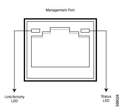
Management Port LEDs
The management port on the vEdge 1000 router has two LEDs that indicate link/activity and port status. See the following figure.
Figure 5. LEDs on the Management Port on a vEdge 1000 Router
The following table describes the LEDs on the management port.
Table 11.
LED
Color
State & Description
Link/Activity
Green
Blinking—Link is up and there is link activity
Steady On— Link is up but there is no link activity
Off —Link is not up
Status
Green/Yellow/Off
Indicates the speed of the link: Green—1000 Mbps Yellow—100 Mbps Off—10 Mbps
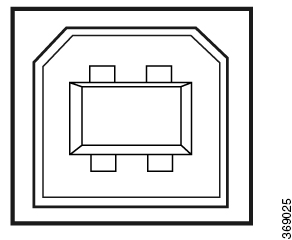
Console Port
The console port on a vEdge 1000 router is accessible via the following external interfaces:
An RS-232 serial interface that uses an RJ-45 connector to connect to a console management device.
A USB serial interface that uses a standard USB Type B connector to connect to a console management device. See the following
figure.
Figure 6. USB Type B Connector
Note
At any given time, you can activate only one of the external interfaces.
The default baud rate for the console port is 115,200 baud.
When you connect a device such as a PC or a terminal server to the console serial port of a vEdge router, ensure that the
PC or terminal serial port is configured to disable flow control.
The following table provides the pinout information for the RJ-45 console port connector. A USB Type-A to Type-B cable is
shipped with the vEdge 1000 router as standard accessory for console port connection.
When you connect a device, such as a PC or a terminal server, to the console port of the vEdge 1000 router, ensure that flow
control is disabled on the device that is connecting to the vEdge router, for the serial port it uses to connect to the vEdge
router.
Table 12.
Pin
Signal
Description
1
RTS Output
Request to send
2
NC
No connect
3
TxD Output
Transmit data
4
Signal Ground
Signal ground
5
Signal Ground
Signal ground
6
RxD Input
Receive data
7
NC
No connect
8
CTS Input
Clear to send
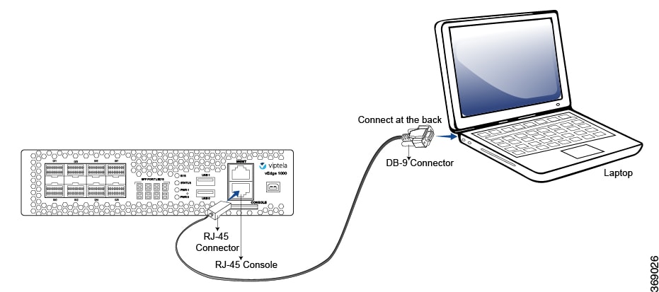
RJ-45–to–DB-9 Serial Port Adapter Pinout
The console port on a vEdge 1000 router is an RS-232 serial interface that uses an RJ-45 connector to connect to a management
device such as a PC or a laptop. If your laptop or PC does not have a DB-9 male connector pin and you want to connect your
laptop or PC to a vEdge 1000 router, use a combination of the RJ-45–to–DB-9 female adapter along with a USB–to–DB-9 male adapter
as shown in the following figure. Note that the vEdge router does not ship with an RJ-45–to–DB-9 serial port adapter cable.
Figure 7. vEdge 1000 Router Connected to a Laptop via RJ-45–to–DB-9 Cable
The following table provides the wiring and pinout information for the RJ-45–to–DB-9 serial port adapter cable.
Table 13.
RJ-45 Pin
Signal
DB9 Pin
Signal
1
RTS
8
CTS
3
TXD
2
RXD
4
GND
5
GND
6
RXD
3
TXD
8
CTS
7
RTS
You can also connect the vEdge 1000 router to a management device such as a PC or a laptop using an RJ-45–to–RJ45 cable as
shown in the following figure. Note that the vEdge router does not ship with an RJ-45–to–RJ-45 cable.
Figure 8. vEdge 1000 Router Connected to a Laptop via RJ-45–to–RJ-45 Cable
Power Supply and Cooling in Cisco vEdge 1000 Routers
The vEdge 1000 router has two built-in fans and ships with two external AC power supply adapters. Read this article to learn
more about the AC power supply adapter in the router as well as about the cooling system and airflow through the router chassis.
AC Power Supply Adapter
You can connect up to two AC power supply adapters to the vEdge 1000 router for redundancy purposes.
The following table provides the power requirements for the external AC power supply adapter for the vEdge 1000 router.
Table 14.
Item
Specification
AC input voltage
90-264 Vrms
AC input line frequency
47-63 Hz
Typical power consumption
28 Watts
Note
It is strongly recommended that you use the power supply adapters provided by Viptela to power your vEdge 1000 router.
AC Power Cord Specifications
The vEdge 1000 router ships with a detachable AC power cord. The power cord has a C13 connector at one end and the other end
is specific to the country/locality to which the product is shipped.
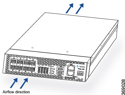
Cooling System and Airflow in vEdge 1000 Router
The vEdge 1000 router has built-in fans that provide front-to-back airflow for the router.
The air intake to cool the chassis is through the perforations in the front of the chassis. Hot air exits from the rear of
the chassis via the vents provided near the fans.
Figure 9. vEdge 1000 Router Airflow
Figure 10. Vents Near the Fan Area of a vEdge 1000 Router
Temperature sensors in the chassis monitor the internal chassis temperature. When a single fan fails at room temperature,
the system can still provide sufficient cooling.
If a fan fails or if the ambient temperature inside the chassis rises above the acceptable range, the router raises an alarm.
If the temperature inside the chassis rises above the maximum threshold temperature, the router shuts down automatically.
Field-Replaceable Units
The vEdge 1000 router is a stiff sheet-metal structure that houses the hardware components. Field-replaceable units (FRUs)
are hardware components that you can remove and replace at your site. The table below lists the FRUs in the vEdge 1000 router.
Table 15. vEdge 1000 Router FRUs
FRU
FRU Model Number
External AC power supply adapters
VEDGE-1000-PWR
Gigabit Ethernet transceivers
SFP-1GE-SX
SFP-1GE-LX
SFP-1GE-Base-T
The transceivers in the router are hot-removable and hot-insertable. You can remove and replace them without powering off
the router or disrupting router functions.
Planning and Installation
This article provides general safety standards to adhere to when installing or connecting a vEdge 1000 router or its components.
General Safety Standards
Install your vEdge router in compliance with the following local, national, and international electrical codes:
United States—National Fire Protection Association (NFPA 70), United States National Electrical Code.
Other countries—International Electromechanical Commission (IEC) 60364, Part 1 through Part 7.
Evaluated to the TN power system.
Canada—Canadian Electrical Code, Part 1, CSA C22.1.
Locate the emergency power-off switch in the room in which you are working. In case of an electrical accident, quickly turn
off the power.
Disconnect power before installing or removing the router.
If an electrical accident occurs, use caution and immediately turn off power to the router.
Make sure that grounding surfaces are thoroughly cleaned and well-finished before grounding connections are made.
Do not work alone if hazardous conditions exist.
Always check that power is disconnected from a circuit. Never assume that it is disconnected.
Carefully inspect your work area for possible hazards, such as moist floors, worn-out power cords, ungrounded power extension
cords, and missing safety grounds.
Operate the device within marked electrical ratings and product usage instructions.
To ensure that the router and the FRUs function safely and correctly, use the specified cables and connectors, and make certain
they are in good condition.
Caution
Before removing or installing router modules and components, ensure that the router chassis is electrically connected to ground.
Ensure that you attach an ESD grounding strap to an ESD point and place the other end of the strap around your bare wrist
making good skin contact. Failure to use an ESD grounding strap could result in damage to the router.
Note
Some router components are hot-swappable and hot-insertable. You can remove and replace them without powering off or disconnecting
power to the router. Do not, however, install the router or any of its component if they appear to be damaged.
Prepare for Router Installation
This article provide guidelines and requirements for preparing your site to install the vEdge 1000 router.
Site Preparation Guidelines
Efficient operation of your vEdge 1000 router requires proper site planning and proper layout of your equipment rack or wiring
closet:
Ensure that the area around the router is kept free of dust and conductive material.
Follow appropriate airflow guidelines so that the cooling system functions normally.
Follow ESD prevention procedures to avoid any damage to the router.
Install the router in an enclosed, secure area allowing only authorized personnel to access the device.
Environmental Requirements
Install the vEdge 1000 router in a dry, clean, temperature-controlled, and well-ventilated environment:
Maintain ambient airflow for the router to operate normally. The ambient intake air temperature should be in the range 0°C
to 40°C (32°F to 104°F). If the airflow is blocked or if the air intake is too warm, the router can get overheated.
Avoid temperature extremes. Ensure that the router is operating at an ambient temperature not more that 40°C (104°F) at sea
level. For higher altitudes, a derating of 1.50°C per 1,000 feet applies.
High humidity conditions can cause moisture to penetrate into the chassis. The device supports 10% to 85% humidity levels,
non-condensing.
Rack Requirements
You can mount the vEdge 1000 router in a two-post or a four-post rack. The following table provides the rack requirements
for the router.
Table 16.
Rack Requirement
Guidelines
Rack type
Use a two-post or a four-post rack that meets the size requirements for the router, provides bracket holes or hole patterns
spaced at 1 U (1.75 in. or 4.45 cm) increments, and is strong enough to support the weight of the router.
Mounting brackets
Ensure that the holes in the mounting brackets are spaced at 1 U (1.75 in. or 4.45 cm). This allows you to mount the router
in any location in the rack.
Rack size
It is recommended that the rack comply with the size and strength standards of a 19-inch rack as defined in Cabinets, Racks, Panels, and Associated Equipment (document number EIA-310–D), published by the Electronics Industry Association ( http://www.eia.org ). Ensure that the rack
rails are spaced widely enough to accommodate the external dimensions of the chassis and that the outer edges of the front
mount brackets extend the width of the chassis to 19 in. (48.2 cm). You must also ensure that the spacing of rails and adjacent
racks allows for the proper clearance around the router and rack.
Rack secured to building structure
For maximum stability, secure the rack to ceiling brackets and to floor brackets.
Airflow Requirements
When planning your site for installing the vEdge 1000 router, allow enough clearance around the installed router. Since the
router works with a front-to-back airflow there are no clearance requirements for the sides, but it is recommended that you
provide at least 3 in. of clearance at the back.
Install the vEdge 1000 Router
Once you have prepared your site for router installation, unpack the vEdge 1000 router and mount it in a 19-inch rack using
the mounting ears shipped with the router. Optionally, you can order the rack-mount kit from Viptela to mount the router.
Read this article for step-by-step instructions for mounting the router in a 19-inch rack.
Unpack the vEdge 1000 Router
A vEdge 1000 router is shipped in a cardboard carton and secured firmly in place with foam packing material. The carton contains
an accessory box and Quick Start instructions. It is recommended that you do not unpack the router till you are ready to
install it.
To unpack the router:
Move the cardboard carton close to the installation site, making sure you have adequate space to remove all the contents of
the box.
Open the top flaps of the carton.
Gradually remove the accessory box and the packing foam holding the router and the accessories in place.
Take out the router and each accessory.
Verify the router components against the packing list included in the box (see packing list below).
Figure 11. Unpacking the vEdge 1000 Router
Note
It is recommended that you do not discard the shipping carton and packing material when you unpack the router. Flatten and
store the box in case you need to move or return the router in the future. See Return Hardware.
Packing List for a vEdge 1000 Router
The cardboard carton in which the router is packed includes a packing list. Check the parts you receive with your router against
the items on the packing list. The packing list specifies the part number, name, and quantity of each item in the carton.
If any part on the packing list is missing, contact your customer service representative or contact Viptela customer support
from within the U.S. or Canada by telephone at 800-525-5033 or by email to support@viptela.com .
The following table lists the parts shipped with the vEdge 1000 router and their quantities.
Table 17.
Component
Quantity
Router chassis
1
AC power adapters
2
AC power cords appropriate for your geographical location
2
Cable ties (to secure the power adapter cord to the rack)
6
USB console cable
1
Mounting ears (right and left)
2
Mounting-ear screws (Packet A)
4
Rack-mount screws (Packet B)
4
vEdge 1000 Router Quick Start document
1
Mount a vEdge 1000 Router Using Mounting Ears
The most common way to mount a vEdge 1000 router is on two front posts in a 19-inch rack using the mounting ears shipped with
the router.
In addition to the items in the accessory box, you need the following tools to mount a vEdge 1000 router in a 19-inch rack:
Number 2 Phillips (+) screwdriver
Tape measure
To mount the vEdge 1000 router on two front posts in a 19-inch rack:
Place the router chassis on the floor or on a sturdy table near the rack.
Verify the internal dimensions of the rack with a tape measure.
Secure the left and right mounting ears to either side of the router chassis using the four shoulder screws in packet A.
Figure 12. Attaching the Mounting Ears to the vEdge 1000 Router Chassis
Grasp both sides of the router, then lift and position it in the rack, making sure that the mounting ear holes are aligned
with the threaded holes in the rack rail.
Secure the mounting ears to the two front posts of the rack using the four rack-mount screws in packet B. Tighten the screws.
Figure 13. Screwing the Mounting Ears to the Rack
Use a tape measure or level to verify that the router is installed straight and the holes at either ends of the rack align
properly.
Tip
t is recommended that you retain the dust covers on any unused ports.
Mount a vEdge 1000 Router Using a Rack-Mount Tray
You can use a rack-mount tray to install the vEdge 1000 router if you want to install two vEdge routers in the same slot in
a 19-inch rack or if you want to mount the router on all four posts of the rack. See Rack-Mount Tray Specifications .
You need to order the rack-mount kit from Viptela separately.
Unpack the Rack-Mount Tray Kit
The rack-mount kit includes a dual rack-mount tray and an accessory box for mounting up to two vEdge routers.
To unpack the rack-mount kit:
Open the top flaps of the cardboard box.
Gradually remove the accessory box and the packing foam holding the rack-mount tray and the accessories in place.
Take out the rack-mount tray and each accessory.
Verify the components against the packing list included in the box (see packing list below).
Figure 14. Unpacking the Rack-Mount Kit
Packing List for the Rack-Mount Tray Kit
The cardboard carton in which the rack-mount tray and the accessory box are packed includes a packing list. Check the parts
you receive with your rack-mount kit against the items on the packing list. The packing list specifies the part number, name,
and quantity of each item in the carton.
If any part on the packing list is missing, contact your customer service representative or contact Viptela customer support from
within the U.S. or Canada by telephone at 800-525-5033 or by email to support@viptela.com .
The following table lists the parts shipped in the rack-mount kit and their quantities.
Table 18.
Component
Quantity
vEdge 1000 dual rack-mount tray
1
Condor AC adapter housing bracket
4
Sparkle AC adapter housing bracket
4
Front stopper
1
Left extended ear
1
Right extended ear
1
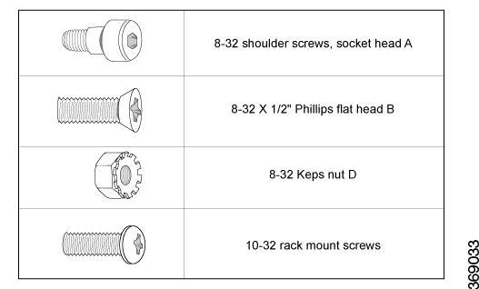
8-32 socket head shoulder screws (A)
8
8-32 X 1/2" flat-head screws (B)
4
8-32 Kep nuts (D)
4
10-32 rack-mount screws
8
Allen key (to use with the #8-32 shoulder screws, socket head 'A')
1
Figure 15. Screws and Nuts Included in the Rack-Mount Kit
Mount a vEdge 1000 Router Using a Rack-Mount Tray
In addition to the rack-mount accessory kit, you need the following tools to mount a vEdge 1000 router in a 19-inch rack using
a rack-mount tray:
Number 2 Phillips (+) screwdriver
Tape measure
Mounting a vEdge 1000 router in a 19-inch rack is a two-step process:
First, you prepare the rack-mount tray for installation by securing the vEdge 1000 router and the AC power adapters to the
tray.
Next, you install the rack-mount tray into the rack.
Prepare the Rack-Mount Tray for Installation
To prepare the rack-mount tray for mounting the vEdge 1000 router on two or four posts in a 19-inch rack:
Place the two AC power adapters, side by side, in their designated slots towards the rear end of the rack-mount tray. If you
are installing two vEdge routers, place four AC power adapters on the tray.
Place the adapter housing bracket over the AC power adapter and secure it in place by screwing down the two thumbscrews attached
to the housing bracket.
Figure 16. Screwing the AC Adapter Housing Bracket to the Rack-Mount Tray
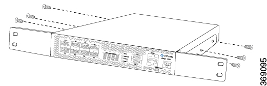
Using the Allen key provided in the rack-mount kit, screw the four 8-32 shoulder screws to either side of the router (two
on each side), as shown in the following figure. If you plan to mount two routers side-by-side on the same rack-mount tray,
screw the nuts to either sides of the second router too.
Figure 17. Screwing the 8-32 Shoulder Screws to the vEdge 1000 Router
Gently slide the vEdge 1000 router into the groove at the front of the rack-mount tray until it goes all the way in. If you
plan to install two routers side by side, gently slide in the second router also.
Figure 18. Sliding the vEdge 1000 Router into the Rack-Mount Tray
Plug the DC 12-volt jack of the AC power adapter into the receptacle at the rear of the router.
Use cable ties to neatly secure, in place, the extra cable on the DC end. To do this, first pass the cable ties through the
two hooks provided on the tray and then tie the cable with it.
Figure 19. Securing the Cable on the DC End with Cable Ties
Note
There are two types of housing bracket sets provided in the rack-mount kit. Use the housing bracket set that fits the AC power
adapter you received with the vEdge 1000 router.
Install the Rack-Mount Tray on Two Front Posts
To install the rack-mount tray on two front posts in a 19-inch rack:
Verify the internal dimensions of the rack with a tape measure. The rack-mount tray is 440 mm wide and must fit within the
mounting posts.
Have one person grasp both sides of the rack-mount tray on which you secured the vEdge router(s) and position it in the rack.
Figure 20. Holding the Rack-Mount Tray with the vEdge Router(s) in Place
Have a second person secure the rack-mount tray to the two front posts of the rack using four rack-mount screws provided in
the rack-mount kit.
Figure 21. Screwing the Rack-Mount Tray to the Two Front Posts of the Rack
Use a tape measure or level to verify that the tray is installed straight and the holes at either end of the rack align properly.
Tip
It is recommended that you retain the dust covers on any unused ports.
Install the Rack-Mount Tray on All Four Posts
To install the rack-mount tray on all four posts in a 19-inch rack:
Verify the internal dimensions of the rack with a tape measure. The rack-mount tray is 440 mm wide and must fit within the
mounting posts.
Have one person grasp both sides of the rack-mount tray on which you secured the vEdge router(s) and position it in the rack.
Figure 22. Holding the Rack-Mount Tray with the vEdge 1000 Router in Place
Have a second person secure the rack-mount tray to the two front posts of the rack using four rack mount screws provided in
the rack-mount kit.
Figure 23. Screwing the Rack-Mount Tray to the Four Posts of the Rack
Screw the L-shaped side of each extended ear bracket (marked Left and Right) to the rear posts of the rack using the 10-32
rack mount screws (two on each side) provided in the rack-mount kit.
Figure 24. Screwing the Extended Ear Bracket to the Four Post Rack
Screw the extended ear brackets to either sides of the rack-mount tray using the 8-32 x 1/2 flat screws and the 8-32 Kep nuts
provided in the accessory kit.
Figure 25. Attaching the Extended Ear Bracket to the Rack-Mount Tray
Use a tape measure or level to verify that the tray is installed straight and the holes at either ends of the rack align properly.
Note
The two extended ear brackets in the rack-mount kit have different part numbers and are not interchangeable.
Note
You may need to adjust the position of the extended ear brackets to match the depth of your rack.
Tip
It is recommended that you retain the dust covers on any unused ports.
Connect the vEdge 1000 Router
This article describes how to connect the vEdge 1000 router to system ground, an AC power source, a management console, and
to a network for out-of-band-management.
Step 1: Connect Earth Ground to the Router
To meet safety and electromagnetic interference (EMI) requirements and to ensure proper operation of your vEdge 1000 router,
connect the router to earth ground before you power it on. To do so, you need a number 2 Phillips (+) screwdriver.
To connect system ground to the vEdge 1000 router:
Connect one end of the grounding cable to a proper earth ground, such as the rack in which the router is mounted.
Secure the grounding lug to the protective grounding terminal with the washers and screws. If you are using the cable clamp
to secure the power cords, slide the grounding lug onto the screw before the cable clamp.
Dress the grounding cable, and make sure that it does not touch or block access to other router components.
Figure 26. Connecting a Grounding Cable to a vEdge 1000 Router
Note
If you plan to mount the vEdge 1000 router on four posts of a rack, mount the router in the rack before attaching the grounding
lug to the router.
Step 2: Connect AC Power to the Router
To connect the vEdge 1000 router to an AC power source:
Attach an ESD grounding strap to your bare wrist. Then connect the strap to the ESD point on the rack.
Plug the AC power adapter cords into inputs PWR 0 and PWR 1 on the back of the router. Note that the second power adapter
is for redundancy. If you are using only one power adapter, you can plug it into PWR 0 or PWR 1.
Secure the power adapter cords in place by loosening the cable clamp screw, tucking the cords under the clamp, and then tightening
the screw as shown in Figure 2.
Plug one end of each power cord into an AC power adapter, and plug the other end into an AC power outlet.
Note
Secure the AC power cord to the side of the rack post with the help of the cable ties supplied with Cisco vEdge 1000 routers.
Figure 27. Connecting an AC Power Supply Adapter to a vEdge 1000 Router
Note
It is strongly recommended that you use the power supply adapter and the power cord supplied with the vEdge 1000 router.
Caution
If you are connecting AC power to the router, it is recommended that the building have an external surge protective device
installed.
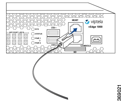
Step 3: Connect the Router to a Management Console
You can configure and manage a vEdge 1000 router using a management console. To connect the router to a management console,
use the console port which accepts a cable with an RJ-45 connector. See Console Port .
To connect the vEdge 1000 router to a management console:
Connect one end of the console cable into the console port, labeled CONSOLE, on the vEdge router (see Figure 3).
Connect the other end of the console cable into the console server or to a management console.
Figure 3: Connecting a vEdge 1000 Router to a Management Console
To use the USB console from a Windows device:
Go to the Device Manager to determine which COM port is being used for the USB serial port.
In the PuTTY SSH/Telnet client, in Connection Type, select Serial. Then, specify the COM port and a speed of 115200.
vEdge 1000 Router Default Configuration
The default configuration file looks like this:
vEdge1000# show running-config
system
 vbond ztp.viptela.com
 aaa
  auth-order local radius tacacs
  usergroup basic
   task system read write
   task interface read write
  !
  usergroup netadmin
  !
  usergroup operator
   task system read
   task interface read
   task policy read
   task routing read
   task security read
  !
  user admin
   password $6$t.vzhbSwOUaaCnRu$<wbr/>AiJYG3VFR1NurXPY7YXSputMMv4hg3<wbr/>Bign362rj4IIWXm7uVfiReqv/<wbr/>4EhKG2QUJSaZnZZPveQYBfIozCioyE<wbr/>/
  !
!
logging
  disk
   enable
  !
 !
!
omp
 no shutdown
 graceful-restart
 advertise connected
 advertise static
!
security
 ipsec
  authentication-type ah-sha1-hmac sha1-hmac
 !
!
vpn 0
 interface ge0/0
  ip dhcp-client
  tunnel-interface
   encapsulation ipsec
   no allow-service bgp
   allow-service dhcp
   allow-service dns
   allow-service icmp
   no allow-service sshd
   no allow-service netconf
   no allow-service ntp
   no allow-service ospf
   no allow-service stun
  !
  no shutdown
!
!
vpn 512
 interface mgmt0
  ip address 192.168.1.1/24
  no shutdown
!
Maintenance and Troubleshooting
Now that you have installed and connected the vEdge 1000 router, you can monitor and troubleshoot the various LEDs and
system alarms on the router.
Alarm Severity Levels
The system alarms on the vEdge 1000 router have two types of severity levels:
Major (red)—Indicates a critical situation on the router resulting from one of two conditions:
One or more hardware components on the router has failed.
One or more hardware components on the router has exceeded the temperature threshold.
A major alarm condition requires immediate attention. If a temperature related major alarm persists for more than five minutes,
the router will shut down.
Minor (yellow)—Indicates a warning on the router that, if left unattended, might result in an interruption in router operation
or degradation in router performance. A yellow alarm condition requires further monitoring and/or maintenance.
Hardware Alarms
Hardware alarms on the vEdge 1000 router are predefined and are triggered by a physical condition on the router such as a
power supply failure, excessive component temperature, or fan failure. The vEdge 1000 router triggers the following types
of hardware alarms:
Main board temperature alarm—The main board of the router has four temperature sensing points (board sensor 1 through 4).
If the temperature of the sensor location crosses the predefined threshold level, the system triggers an alarm.
CPU and DRAM temperature alarm—If the temperature of the system CPU or of the DRAM module crosses the predefined threshold
level, the system triggers an alarm.
Fan alarm—The router has fixed built-in fans for system cooling which run at a fixed speed. If a fan stops running, the system
triggers an alarm. Also if a fan starts to run below a predefined RPM threshold, the system triggers an alarm.
Power supply alarm—The router has two power adapter inputs for redundancy reasons. If one of the power adapters is not plugged
in or there is a failure on a power adapter input, the system triggers an alarm.
The following table lists the yellow and red alarm threshold for the six temperature sensing points in the system—four board
sensors spread across the board, 1 CPU junction temperature sensor, and 1 DRAM temperature sensor). The lower threshold value
(Bad Fan) applies if a fan failure condition is also detected; otherwise, the higher threshold value applies (normal).
Table 19.
Item
Yellow Alarm(degrees C)
Red Alarm(degrees C)
Normal
Bad Fan
Normal
Bad Fan
Chassis board sensor1
65
60
80
75
Chassis board sensor2
65
60
80
75
Chassis board sensor3
65
60
80
75
Chassis board sensor4
65
60
80
75
CPU junction temperature
85
80
100
95
DRAM DIMM
65
60
80
75
Checking Alarms and Notifications
To view the current chassis environment condition , enter the show hardware environmentcommand at the system prompt. The system displays the power supply status, temperature sensor readings, fan speed, and related
alarm status if any exists.
To view the severity of active alarms, enter the show hardware alarms command at the system prompt. The system displays the alarm severity and a brief description of the cause of each active
alarm.
To view temperature thresholds at which green, yellow, and red alarms are generated, enter the show hardware temperature-thresholds command at the system prompt. The system displays the alarm temperature threshold information for a specific board or all
boards in the router and for the router's CPU and DRAM.
To view all other events on a Viptela device, enter the show notification stream command. The system displays notifications about events that have occurred on the Viptela device.
LEDs
The chassis LEDs located on the front panel of the vEdge 1000 router indicate the status of the router.
If there are one or more major alarms active in the router, the SYS LED is lit red. If there are one or more minor alarms
active in the router, the SYS LED is lit amber. See Front Panel Components for details of the LEDs and the status they indicate.
Install a Transceiver
The transceivers for the vEdge 1000 router are hot-removable and hot-insertable field-replaceable units (FRUs). You can remove
and replace them without powering off the router or disrupting router functions.
Caution
Before you install a transceiver or any component in the router chassis, make sure that you understand how to prevent electrostatic
discharge (ESD) damage. See General Safety Standards.
Note
It is recommended that you purchase the optical transceivers and optical connectors for the vEdge router from Viptela.
Install a Transceiver
To install a transceiver in a vEdge router:
Gently remove the new transceiver from the plastic bag in which it was shipped.
If the port in which you plan to install the transceiver is covered with a dust cover, remove the cover, and save it for later
use.
Carefully slide the transceiver in the empty port until it is firmly seated.
Remove the safety cap when you are ready to connect an optic fiber cable to the port.
Figure 28. Installing a Transceiver in a vEdge 1000 Router
Warning
Do not look directly into fiber-optic transceivers and fiber-optic cables connected to a transceiver as they emit laser light
that can damage your eyes.
Remove a Transceiver
The transceivers for the vEdge router are hot-removable and hot-insertable field-replaceable units (FRUs). You can remove
and replace them without powering off the router or disrupting router functions.
Caution: Before you remove a transceiver or any component from the router chassis, make sure that you understand how to prevent
Electrostatic discharge (ESD) damage. See General Safety Standards .
Note: It is recommended that you purchase the optical transceivers and optical connectors for the vEdge router from Viptela.
Remove a Transceiver
To remove any type of transceiver from a vEdge router, you need the following parts and tools:
A transceiver slot dust cover
An antistatic mat or an electrostatic bag
A rubber safety cap for the transceiver
To remove any type of transceiver from a vEdge router:
Place the antistatic mat or the electrostatic bag on a firm, flat surface.
Attach the ESD grounding strap to your bare wrist. Then connect the strap to the ESD point on the rack.
Label the cables connected to the transceiver so that you can reconnect them correctly later.
Remove the cable connector from the transceiver.
Unlock the transceiver by pulling down the ejector handle from the transceiver.
Grasp the transceiver ejector handle and pull the transceiver approximately 0.5 in. out of the router.
Using your fingers, grasp the body of the transceiver and pull it out of the router completely.
Place a rubber safety cap over the transceiver.
Place the removed transceiver on the antistatic mat or in an electrostatic bag.
If you are not installing a new transceiver, place the transceiver slot dust cover over the empty port.
Warning
Do not look directly into fiber-optic transceivers and fiber-optic cables connected to a transceiver as they emit laser light
that can damage your eyes.
Restore a vEdge Router
This article explains how to revert the configuration for a vEdge router to the factory-default values. It also explains how
to do a soft and hard reset of the router.
Reverting to the vEdge Router Factory-Default Configuration
After you set up and start the virtual machines (VMs) for the vEdge Cloud routers and set up and start the hardware vEdge
routers in your overlay network, they come up with a factory-default configuration . When you make and commit changes to
the default configuration, a new configuration file is created. This new configuration file then becomes the active configuration.
If desired, you can revert to the default factory configuration:
vEdge# request software reset
Reset the Router
You can reset the vEdge router by doing either a hard press or a soft press. To perform either type of press, locate the Reset
button on the front panel of the router. The Reset button is recessed to avoid accidentally pressing it while the router is
operational. To press the Reset button, use a sharp narrow tool.
Perform a Long Press Reset
A long press reset of the vEdge router erases passwords, keys, and most other configuration parameters, restoring the router
to its factory-default configuration.
To perform a long press reset, press the Reset button for more than 10 seconds. After you release the Reset button, the router
will reboot and resume normal operation.
Perform a Short Press Reset
A short press reset of the Edge router is equivalent to a graceful software reboot and is the same as entering the reboot command at the CLI prompt.
To perform a short press reset, press the Reset button for two seconds. The short press reset takes effect almost instantaneously
and reboots the router.
Return Hardware
This article describes how to return a vEdge router or a hardware component to Viptela for repair or replacement.
Locate Serial and Model Number
To return a vEdge router or a hardware component to Viptela, you need the serial and model number of the router or the component
being returned.
You can locate the serial and model number of a vEdge router in one of the following ways:
In vManage NMS, select the Configuration ► Devices screen. The device table lists the serial and model numbers of the routers
in the network.
Enter the show hardware inventory command at the CLI prompt.
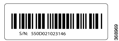
The serial number is printed on a label on the right side of the router; the model number is printed on a label on the back
of the router.
Figure 29. Sample Serial Number Label for a vEdge Router
Obtain an RMA Number
If you are returning a vEdge router or a hardware component to Viptela for repair or replacement, contact the Viptela Customer
Support team to open a support case and obtain a Return Materials Authorization (RMA) number.
Before you open a case and request an RMA number, keep the following information ready:
Your existing service contract number, if you have one
Serial number of the router or component
Model number of the router or component
Physical location of the router
Your name, organization name, telephone number, fax number, and shipping address
Failure or problem description with details
Type of activity being performed on the router when the problem occurred
Configuration data displayed by one or more show commands
To obtain an RMA number:
Open a support case with Viptela in one of the following ways:
Log in to www.viptela.com/support
Send email to support@viptela.com
Call toll-free 800-525-5033
A Viptela Customer Support representative validates your request and issues an RMA number for returning the router or a hardware
component.
Note
Do not return the router or any component to Viptela before first obtaining an RMA number. Viptela reserves the right to refuse
to take any shipment that does not have an RMA number.
Repack the Router
If you need to move or return the vEdge router, repack the router in its original packing. Before you repack the router follow
these steps:
Shut down the vEdge router by issuing the poweroff command at the CLI prompt.
Disconnect power to the router.
Remove the cables and transceivers.
You will need the following tools to repack the router:
Phillips Number 2 (+) screwdriver
Cardboard carton and original packing in which you received the router
To repack the router in its original packing:
If you do not have a vEdge 1000 router, skip this step. Otherwise:
If the router is installed in a rack using the rack-mount kit from Viptela, remove the front stopper screwed along the front
side of the rack-mount tray.
Then remove the rack-mount tray from the rack by having one person support the weight of the rack-mount tray while a second
person unscrews the rack-mount screws.
Place the rack-mount tray on a firm, flat surface.
Slide out the vEdge 1000 router from the rack-mount tray.
Place the router chassis in the plastic packing bag.
Place the side packing foam on both sides of the router chassis.
Secure the chassis in the cardboard carton.
Secure the top of the chassis by placing the top packing foam over the top of the chassis.
Close the cardboard shipping box and seal it with packing tape.
Write the RMA number on top of the box for purposes of tracking.
If you are returning any field-replaceable units with the router, repack them as described in Repack Router Components below.
Repack Router Components
If you need to return any router components, follow these steps:
Ensure that you have the antistatic bag for each component and an ESD grounding strap.
Place each component in its antistatic bag.
Pack each component in its original packing material. If you do not have the original packing material, ensure that the component
is packed adequately with packing material to prevent any damage in transit.
Place the component in the original cardboard box or another cardboard box if the original is not available.
Secure the box with tape.
Write the RMA number on top of the box for purposes of tracking.


 Feedback