vEdge 100 Router

The vEdge 100 router delivers highly secure site-to-site data connectivity to small business and home offices (SOHO). The vEdge 100 router is a fixed-port-configuration router with the following features:

  • Five built-in 10/100/1000 Mbps Ethernet ports 

  • Power over Ethernet (PoE) source support on one Ethernet port

  • Encryption and QoS support

  • 100 Mbps aggregate bandwidth (IPSEC IMIX)

  • Secure identification chip for anti-counterfeit and secure authentication

  • Integrated power supply

  • Kensington security lock slot to physically lock down the router

  • Desktop mount, wall mount, or rack-mountable in a 19-inch rack

Chassis Views

The following figures show the front and back panels of the vEdge 100 router, indicating the location of the power interfaces, status indicators, and chassis identification labels.

Figure 1. Front Panel of the vEdge 100 Router
Figure 2. Back Panel of the vEdge 100 Router

Declaration of Conformity

The Viptela products are controlled under the Commerce Control List (CCL) of the U.S. Export Administration Regulations (EAR) as networking equipment within the following U.S. Export Control Classification Numbers (ECCN): 5A002, 5D002, and 5E002.

The vEdge hardware and software products and the Viptela encryption technology can be delivered to most end users and destinations worldwide without a licensing requirement. The Viptela solution and products have undergone a one-time review by the Government of the United States of America and qualify for License Exception ENC. As such, they are eligible for export according to Section 740.17 of the EAR.

The Viptela solutions and products can be delivered to most end users worldwide, except to entities or end users in the following countries: Cuba, Iran, North Korea, Sudan, and Syria.

Controlled Technologies

Viptela manages technology subject to the U.S. Export Administration Regulations (EAR). These controlled technologies may include items under U.S. ECCN 5E002 encryption technology. The Viptela encryption technology is for the development, production, and use of Viptela products that implement or use encryption.

The Viptela software distribution policy allows only authenticated users to download the Viptela encryption software. Recipients of controlled technology are obliged to maintain adequate controls to prevent nationals from outside the U.S. and Canada from accessing Viptela information, subject to ECCN5E002, without first obtaining authorization from the U.S. government.

For additional information on controlled technologies, please contact Viptela support at support@viptela.com .

Components and Specifications

This article provides the chassis specifications of the vEdge 100 router and lists the other router components.

Chassis Specifications

The following table lists the specifications for the vEdge 100 router chassis.

Table 1.

Item

Specification

Services and Slot Density

RJ45 Ports 10/100/1000 Mbps

5 ports, one of which has 802.3af PoE source capability

Embedded hardware-based crypto acceleration (IPSec)

Yes

Memory DDR3 ECC DRAM

2 GB

NAND storage (internal)

4 GB

USB host port (Type A USB 3.0)

1

Mini USB connector console port (default baud rate 115.2 Kbps)

1

Power supply 

 AC Input   (C6 inlet connector)

Power Specifications

AC input voltage

90-264 Vrms

AC input line frequency

47-63 Hz

Typical power consumption with PoE disabled on ge0/0

15 Watts

Typical power consumption with PoE enabled on ge0/0

32 Watts maximum

Physical Specifications

Chassis height

1.5 in. (3.8 cm)

Chassis width

9 in. (22.9 cm)

Chassis depth

5.5 in. (14 cm)

Rack height

Can be accommodated in 1 RU

Chassis weight

3.1 lb (1.4 kg)

Rack-mount accessory kit 19 in (48.3 cm) EIA

Provided with the unit

Packaging Specifications

Package height

2.5 in. (6.4 cm)

Package width

12.4 in. (31.6 cm)

Package depth

9.6 in. (24.4 cm)

Operating Condition

Temperature

0 to 40°C (32 to 104°F) at sea level ( temperature de-rating of 1.5 deg C per 1000 feet of altitude applicable up to max of 10000 feet or 3000 m)

Altitude

Max 3000 m (10000 ft)

Humidity

10 to 85% RH

Transportation/Storage Condition

Temperature

-40 to 70°C (-40 to 158°F)

Humidity

5 to 95%RH

Altitude

4570 m (15000 ft)

Reliability

MTBF

104K hours

Regulatory Compliance

Safety

AS/NZS 60950-1 CAN/CSA 60950-1 CB-IEC60950-1 CE Marking EN 60950-1 UL60950-1

EMC

AS/NZS CISPR22 Class A EN 300 386 EN 55022 Class A FCC Class A ICES Class A VCCI Class A

Environmental

ROHS 6/6

Front and Rear Panel Components

This article describes the components on the front and rear panels of the vEdge 100 router. See At a Glance for the exact location of these components on the router.

Front Panel LEDs

The vEdge 100 router has five chassis status LEDs located in the front. See the following figure.

Figure 3. Chassis Status LEDs in a vEdge 100 Router

The following table describes the LEDs , their color and states, and the status they indicate.

Table 2.

LED

Color

Status

Power

Green/Red

  • Off: System is not on

  • Green: System is healthy and operating fine

  • Red: Power supply fault

Status

Green/Yellow/Red

  • Off: System is not on

  • Solid Green: System is fully functional

  • Blinking Green: System is booting up

  • Solid Yellow: No Internet connectivity or the system has detected a minor alarm

  • Red: System has detected a major system level fault or alarm

Ethernet Port (LED 0–4)

Green/Yellow

  • Off: No link

  • Solid Green: 1000 Mbps link detected

  • Blinking Green: 1000 Mbps link detected and link activity

  • Solid yellow: 10/100 Mbps link detected

  • Blinking Yellow: 10/100 Mbps link detected and link activity

Rear Panel

The rear panel of the vEdge 100 router has a Reset button, a Kensington security lock slot, and a GPS antenna input. See Chassis Views for the location of these components.

Reset Button

The Reset button on the rear panel is recessed, to avoid accidentally pressing it while the router is operational. To press the Reset button, use a sharp narrow tool. The following table describes the effects of pressing the Reset button.

Table 3.

Press Duration

Behavior

Short press

Pressing for two seconds resets and reboots the router.

Long press

Pressing for 10 seconds resets the router and reboots it with factory default configuration.

Kensington Security Lock Slot

The rear panel of the vEdge 100 router has a small metal-enforced hole for attaching a Kensington lock to secure the router.

Ports and Connectors

The vEdge 100 router supports three types of ports: RJ-45 Ethernet ports, USB port, and USB serial console port.

RJ-45 Ethernet Ports

There are five built-in RJ-45 Ethernet ports on the vEdge 100 router. These ports support 10/100/1000 Mbps and are numbered 0 through 4. Port 0 supports PoE capability.

The following figure provides the pinout information for the RJ-45 ports. The RJ-45 ports comply with the 801 standards.

Figure 4. RJ-45 Ports Pinout Information

USB Port

There is one USB port on the vEdge 100 router with a type A connector. The USB port complies with USB 3.0 specification.

Console Port

The console port on the vEdge 100 router is a serial port and is accessible via a USB Mini-B connector. See the following figure.

Figure 5. FUSB Mini-B Connector

A USB Type-A to Mini-B connector cable is shipped with the vEdge 100 router as standard accessory for console port connection.


Note

When you connect a device such as a PC or a terminal server to the console serial port of a vEdge router, ensure that the PC or terminal serial port is configured to disable flow control.


Power Supply and Cooling System

The vEdge 100 router has an built-in AC-to-DC power supply unit. Read this article to learn more about the AC power supply in the router as well as about the cooling system and airflow through the router chassis.

AC Power Supply in vEdge 100 Router

The vEdge 100 router has an integrated AC power supply that exposes a C6 male AC inlet connector externally. The unit can be powered by connecting the supplied power cord to AC mains with the C5 female connector end of power cord plugged into the unit.

The following table describes the AC power supply specifications for the vEdge 100 router.

Table 4.

Item

Specification

AC input voltage

90-264 Vrms

AC input line frequency

47-63 Hz

Typical power consumption with PoE disabled on transport interface

15 Watts

Typical power consumption with PoE enabled on transport interface

32 Watts maximum

AC Power Cord Specifications

The vEdge 100 router ships with a detachable AC power cord. The power cord has a C5 female connector at one end and the other end is specific to the country/locality to which the product is shipped.

Cooling System in a vEdge 100 Router

The cooling system in a vEdge 100 router consists of internal heat sinks and an internal fan with adjustable speed. The fan speed is algorithmically controlled, based on readings obtained from internal temperature sensors that in turn is determined by factors such as external ambient as well as the traffic workload.

If the ambient temperature inside the chassis rises above the acceptable range, the router raises an alarm. If the temperature inside the chassis rises above the maximum threshold temperature, the router shuts down automatically.

General Safety Standards


Caution

Before removing or installing router modules and components, ensure that the router chassis is electrically connected to ground. Ensure that you attach an ESD grounding strap to an ESD point and place the other end of the strap around your bare wrist making good skin contact. Failure to use an ESD grounding strap could result in damage to the router.


Caution

Some router components are hot-swappable and hot-insertable. You can remove and replace them without powering off or disconnecting power to the router. Do not, however, install the router or any of its component if they appear to be damaged.


  • Install your vEdge router in compliance with the following local, national, and international electrical codes:

    • United States—National Fire Protection Association (NFPA 70), United States National Electrical Code.

    • Other countries—International Electromechanical Commission (IEC) 60364, Part 1 through Part 7.

    • Evaluated to the TN power system.

    • Canada—Canadian Electrical Code, Part 1, CSA C22.1.

  • Permit only trained and qualified personnel to install or replace switch components.

  • Locate the emergency power-off switch in the room in which you are working. In case of an electrical accident, quickly turn off the power.

  • Disconnect power before installing or removing the router.

  • If an electrical accident occurs, use caution and immediately turn off power to the router.

  • Make sure that grounding surfaces are thoroughly cleaned and well-finished before grounding connections are made.

  • Do not work alone if hazardous conditions exist.

  • Always check that power is disconnected from a circuit. Never assume that it is disconnected.

  • Carefully inspect your work area for possible hazards, such as moist floors, worn-out power cords, ungrounded power extension cords, and missing safety grounds.

  • Operate the device within marked electrical ratings and product usage instructions.

  • To ensure that the router and the FRUs function safely and correctly, use the specified cables and connectors, and make certain they are in good condition.

Site Preparation Guidelines

Efficient operation of routers requires proper site planning and proper layout of your equipment rack or wiring closet:

  • Ensure that the area around the router is kept free of dust and conductive material.

  • Follow appropriate airflow guidelines so that the cooling system functions normally.

  • Follow ESD prevention procedures to avoid any damage to the router.

  • Install the router in an enclosed, secure area allowing only authorized personnel to access the device.

Airflow Requirements

When planning your site for installing vEdge routers, allow enough clearance around the installed router. Since the routers work with a front-to-back airflow there are no clearance requirements for the sides, but it is recommended that you provide at least 3 inches of clearance at the back.

Install the vEdge 100 Router

Once you have prepared your site for router installation, unpack the vEdge 100 router and mount it either on the wall or in a 19-inch rack.

Unpack the vEdge 100 Router

A vEdge 100 router is shipped in a cardboard carton and secured firmly in place with foam packing material. The carton contains a packing list and Quick Start instructions. It is recommended that you do not unpack the router till you are ready to install it.

To unpack the router:

  1. Open the top flaps of the carton.

  2. Gradually remove the packing foam holding the router and the accessories in place. See the following figure.

  3. Take out the router and each accessory.

  4. Verify the router components against the packing list included in the box (see packing list below).

Figure 6. Unpacking the vEdge 100 Router

Note: It is recommended that you do not discard the shipping carton and packing material when you unpack the router. Flatten and store the box in case you need to move or return the router in the future. See Return Hardware .

Packing List for a vEdge 100 Router

The cardboard carton in which the router is packed includes a packing list. Check the parts you receive with your router against the items on the packing list. The packing list specifies the part number, name, and quantity of each item in the carton.

If any part on the packing list is missing, contact your customer service representative or contact Viptela customer support from within the U.S. or Canada by telephone at 800-525-5033 or by email to support@viptela.com .

The following table lists the parts shipped with the vEdge 100 router and their quantities.

Table 5.

Component

Quantity

Router chassis

1

AC power cord appropriate for your geographical location (ferrite bead attached)

1

USB console cable

1

Ferrite bead and key (to be attached to the USB cable)

1 + 1

Mounting ears, left and right

2

Wall-mount bracket

1

Mounting ears screws (Packet A)

4

Rack-mount screws (Packet B)

4

Lock plate and screw (Packet C) 

1

Wall-mount screws (Packet D)

4

Quick Start document

1

Mount the vEdge 100 Router

You can mount the vEdge 100 router in one of the following ways:

  • Mount the router in a 19-inch rack

  • Mount the router on the wall

In addition to the accessory box, you need the following tools to mount a vEdge 100 router:

  • Number 2 Phillips (+) screwdriver

  • Tape measure or level

Mount the vEdge 100 Router in a Rack

You can mount the vEdge 100 router on two front posts in a 19-inch rack using simple rack mount ear accessories. To do so:

  1. Place the router chassis on the floor or on a sturdy table near the rack.

  2. Verify the internal dimensions of the rack with a tape measure. The rack-mount tray is 440 mm wide and must fit within the mounting posts.

  3. Secure the left and right mounting ears to either side of the router chassis using the four screws (two on each side) in the packet marked A.

    Figure 7. Attaching the Mounting Ears to the vEdge 100 Router Chassis
  4. Grasp both sides of the router, then lift and position it in the rack, making sure that the mounting ear holes are aligned with the threaded holes in the rack rail.

    Figure 8. Positioning the vEdge 100 Router in the Rack
  5. Secure the mounting ears to the two front posts of the rack using the four rack-mount screws (two on each side) in the packet marked B. Tighten the screws.

    Figure 9. Attaching the Mounting Ears to the Rack
  6. Use a tape measure or level to verify that the tray is installed straight and the holes at either ends of the rack align properly.

  7. Secure the router with a Kensington lock. To do so, first attach the lock plate from packet C to the back of the chassis, then insert the lock in the slot.

    Figure 10. Securing the Router with a Kensington Lock

Tip: It is recommended that you retain the dust covers on any unused ports.

Mount the vEdge 100 Router on the Wall

To mount the vEdge 100 router on the wall:

  1. Screw the four shoulder screws in the packet marked D into the pre-drilled holes on the underside of the router chassis as shown in Figure 6. Tighten the screws until wrist tight. Note that the screw heads will not be flush with the chassis bottom.

    Figure 11. Attach Screws to the Underside of the vEdge 100 Router Chassis
  2. Secure the mounting plate to the wall using four screws appropriate for your wall type (screws not included). Ensure that the L-shaped bracket of the mounting plate is to the upper left.

    Figure 12. Securing the Mounting Plate to the Wall
  3. Mount the router on the mounting plate by aligning the four screws on the underside of the router chassis to the holes in the mounting plate. Then gently slide the router chassis into the slots.

    Figure 13. Mounting the vEdge 100 Router on the Mounting Plate
  4. Secure the router by aligning the round hole on the L-shaped bracket of the mounting plate with the screw hole in the rear of the router chassis. Then attach the L-shaped bracket to the router using a mounting ear screw from packet A.

    Figure 14. Securing the vEdge 100 Router to the Mounting Plate
  5. Secure the router with a Kensington security lock using the slot in the rear of the chassis.

    Figure 15. Securing the Router with a Kensington Security Lock

Connect the vEdge 100 Router

This article describes how to connect the vEdge 100 router to an AC power source and to a management console.

Connect AC Power to the Router

To connect the vEdge 100 router to an AC power source, plug one end of the AC power cord into the back of the router, and plug the other end into an AC power outlet as shown in the following figure.

Figure 16. Connecting AC Power Supply to a vEdge 100 Router

Note

It is strongly recommended that you use the power cord supplied with the router.


Caution

If you are connecting AC power to the router, it is recommended that the building have an external surge protective device installed.


Connect the Router to LAN and WAN Interfaces

To connect the vEdge 100 router to the LAN, plug the appropriate cable into any port except Port 4 on the front of the router.

To connect the vEdge 100 router to a WAN, plug the appropriate cable into Port 4 on the front of the router.

Figure 17. Connecting a vEdge 100 Router to LAN and WAN Interfaces

Connect the Router to a Management Console

To connect the vEdge 100 router to a management console:

  1. Connect one end of the USB Type-A to Mini-B connector cable into the console port, labeled CONSOLE, on the vEdge router.

  2. Connect the other end of the console cable into a management console.

Figure 18. Connecting a vEdge 100 Router to a Management Console

To use the USB console from a Windows device:

  1. In the Device Manager, determine which COM port is being used for the USB serial port.

  2. In the PuTTY SSH/Telnet client, in Connection Type, select Serial. Specify the COM port and a speed of 115200.

Figure 19. PuTTY Configuration

To use the USB console from a Macintosh device:

  1. Install the necessary USB serial driver to enable you to connect the Macintosh to the console port of the router.

  2. Launch the Terminal utility.

  3. From a terminal shell, access the console port with this command:
    $ screen /dev/tty.usbserial* 115200,cs8

vEdge 100 Router Default Configuration

The default configuration file looks like this:

vEdge100# show running-config
system
 vbond ztp.viptela.com
 aaa
  auth-order local radius tacacs
  usergroup basic
   task system read write
   task interface read write
  !
  usergroup netadmin
  !
  usergroup operator
   task system read
   task interface read
   task policy read
   task routing read
   task security read
  !
  user admin
   password $6$qtmMiZWj6W6Kh3nr$<wbr/>MAyIfWUVDPDP2q04LqhdIi6kSXySX7<wbr/>fudpwNOg1.<wbr/>6e4XgpKwwNMkV7gx69O4WWtnvLnUg8<wbr/>aoUGw972PHMNati1
  !
 !
 logging
  disk
   enable
  !
 !
!
omp
 no shutdown
 graceful-restart
 advertise connected
 advertise static
!
security
 ipsec
  authentication-type ah-sha1-hmac sha1-hmac
 !
!
vpn 0
 interface ge0/4
  ip dhcp-client
  tunnel-interface
   encapsulation ipsec
   allow-service dhcp
   allow-service dns
   allow-service icmp
   no allow-service sshd
   no allow-service ntp
   no allow-service stun
  !
  no shutdown
 !
!
vpn 512
!

Maintenance and Troubleshooting

Now that you have installed and connected the vEdge 100 router, you can monitor and troubleshoot the various LEDs and system alarms on the router.

Alarm Severity Levels

The system alarms on the vEdge 100 router have two types of severity levels:

  • Major (red)—Indicates a critical situation on the router resulting from one of two conditions:
    • One or more hardware components on the router has failed.

    • One or more hardware components on the router has exceeded the temperature threshold.

A major alarm condition requires immediate attention. If a temperature related major alarm persists for more than five minutes, the router will shut down.

  • Minor (yellow)—Indicates a warning on the router that, if left unattended, might result in an interruption in router operation or degradation in router performance. A yellow alarm condition requires further monitoring and/or maintenance.

Hardware Alarms

Hardware alarms on the vEdge 100 router are predefined and are triggered by a physical condition on the router such as a power supply failure, excessive component temperature, or fan failure. The vEdge 100 router triggers the following types of hardware alarms:

  • Main board temperature alarm—The main board of the router has one temperature sensing point (board sensor 0). If the temperature of the sensor location crosses the predefined threshold level, the system triggers an alarm.

  • CPU temperature alarm—If the temperature of the system CPU crosses the predefined threshold level, the system triggers an alarm.

  • Fan alarm—The router has a fixed built-in fan for system cooling which runs at a fixed speed. If the fan stops running, the system triggers an alarm. Also if the fan starts to run below a predefined RPM threshold, the system triggers an alarm.

Table 1 lists the yellow and red alarm threshold for the temperature sensing points in the system—one board sensor on the board and one CPU junction temperature sensor. The lower threshold value (Bad Fan) applies if a fan failure condition is also detected; otherwise the higher threshold value applies (normal).

Table 6.

Item

Yellow Alarm(degrees C)

Red Alarm(degrees C)

Normal

Bad Fan

Normal

Bad Fan

Board sensor 0

65

60

80

75

CPU junction temperature

80

75

95

90

Checking Alarms and Notifications

To view the current chassis environment condition , enter the show hardware environment  command at the system prompt. The system displays the power supply status, temperature sensor readings, fan speed, and related alarm status if any exists.

To view the severity of active alarms, enter the show hardware alarms command at the system prompt. The system displays the alarm severity and a brief description of the cause of each active alarm.

To view temperature thresholds at which green, yellow, and red alarms are generated, enter the  show hardware temperature-thresholds command at the system prompt. The system displays the alarm temperature threshold information for a specific board or all boards in the router and for the router's CPU.

To view all other events on a Viptela device, enter the show notification stream command. The system displays notifications about events that have occurred on the Viptela device.
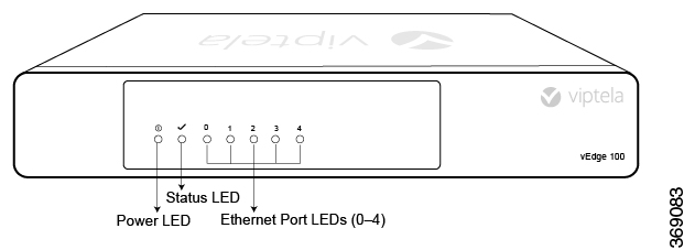
LEDs

The chassis LEDs located on the front panel of the vEdge 100 router indicate the status of the router.

If there are one or more major alarms active in the router, the Status LED is lit red. If there are one or more minor alarms active in the router, the Status LED is lit solid yellow. See Front and Rear Panel Components for details of the LEDs and the status they indicate.

Additional Information

show hardware alarms show hardware environment show notification stream show hardware temperature-thresholds Front and Rear Panel Components Check Alarms and Events

Restore a vEdge Router

This article explains how to revert the configuration for a vEdge router to the factory-default values. It also explains how to do a soft and hard reset of the router.

Reverting to the vEdge Router Factory-Default Configuration

After you set up and start the virtual machines (VMs) for the vEdge Cloud routers and set up and start the hardware vEdge routers in your overlay network, they come up with a factory-default configuration . When you make and commit changes to the default configuration, a new configuration file is created. This new configuration file then becomes the active configuration.

If desired, you can revert to the default factory configuration:

vEdge# request software reset

Reset the Router

You can reset the vEdge router by doing either a hard press or a soft press. To perform either type of press, locate the Reset button on the front panel of the router. The Reset button is recessed to avoid accidentally pressing it while the router is operational. To press the Reset button, use a sharp narrow tool.

Perform a Long Press Reset

A long press reset of the vEdge router erases passwords, keys, and most other configuration parameters, restoring the router to its factory-default configuration.

To perform a long press reset, press the Reset button for more than 10 seconds. After you release the Reset button, the router will reboot and resume normal operation.

Perform a Short Press Reset

A short press reset of the Edge router is equivalent to a graceful software reboot and is the same as entering the reboot command at the CLI prompt.

To perform a short press reset, press the Reset button for two seconds. The short press reset takes effect almost instantaneously and reboots the router.

Return Hardware

This article describes how to return a vEdge router or a hardware component to Viptela for repair or replacement.

Locate Serial and Model Number

To return a vEdge router or a hardware component to Viptela, you need the serial and model number of the router or the component being returned.

You can locate the serial and model number of a vEdge router in one of the following ways:

  • In vManage NMS, select the Configuration ► Devices screen. The device table lists the serial and model numbers of the routers in the network.

  • Enter the show hardware inventory command at the CLI prompt.

  • The serial number is printed on a label on the right side of the router; the model number is printed on a label on the back of the router.

    Figure 20. Sample Serial Number Label for a vEdge Router

Obtain an RMA Number

If you are returning a vEdge router or a hardware component to Viptela for repair or replacement, contact the Viptela Customer Support team to open a support case and obtain a Return Materials Authorization (RMA) number.

Before you open a case and request an RMA number, keep the following information ready:

  • Your existing service contract number, if you have one

  • Serial number of the router or component

  • Model number of the router or component

  • Physical location of the router

  • Your name, organization name, telephone number, fax number, and shipping address

  • Failure or problem description with details

  • Type of activity being performed on the router when the problem occurred

  • Configuration data displayed by one or more show commands

To obtain an RMA number:

  1. Open a support case with Viptela in one of the following ways:

  • Log in to www.viptela.com/support

  • Send email to  support@viptela.com

  • Call toll-free 800-525-5033

  1. A Viptela Customer Support representative validates your request and issues an RMA number for returning the router or a hardware component.

Note: Do not return the router or any component to Viptela before first obtaining an RMA number. Viptela reserves the right to refuse to take any shipment that does not have an RMA number.

Repack the Router

If you need to move or return the vEdge router, repack the router in its original packing. Before you repack the router follow these steps:

  1. Shut down the vEdge router by issuing the poweroff command at the CLI prompt.

  2. Disconnect power to the router.

  3. Remove the cables and transceivers.

You will need the following tools to repack the router:

  • Phillips Number 2 (+) screwdriver

  • Cardboard carton and original packing in which you received the router

To repack the router in its original packing:

  1. If you do not have a vEdge 1000 router, skip this step. Otherwise:

    1. If the router is installed in a rack using the rack-mount kit from Viptela, remove the front stopper screwed along the front side of the rack-mount tray.

    2. Then remove the rack-mount tray from the rack by having one person support the weight of the rack-mount tray while a second person unscrews the rack-mount screws.

    3. Place the rack-mount tray on a firm, flat surface.

    4. Slide out the vEdge 1000 router from the rack-mount tray.

  2. Place the router chassis in the plastic packing bag.

  3. Place the side packing foam on both sides of the router chassis.

  4. Secure the chassis in the cardboard carton.

  5. Secure the top of the chassis by placing the top packing foam over the top of the chassis.

  6. Close the cardboard shipping box and seal it with packing tape.

  7. Write the RMA number on top of the box for purposes of tracking.

If you are returning any field-replaceable units with the router, repack them as described in Repack Router Components below.

Repack Router Components

If you need to return any router components, follow these steps:

  1. Ensure that you have the antistatic bag for each component and an ESD grounding strap.

  2. Place each component in its antistatic bag.

  3. Pack each component in its original packing material. If you do not have the original packing material, ensure that the component is packed adequately with packing material to prevent any damage in transit.

  4. Place the component in the original cardboard box or another cardboard box if the original is not available.

  5. Secure the box with tape.

  6. Write the RMA number on top of the box for purposes of tracking.