Cisco IoT Field Network Director User Guide, Release 4.12.x
Bias-Free Language
The documentation set for this product strives to use bias-free language. For the purposes of this documentation set, bias-free is defined as language that does not imply discrimination based on age, disability, gender, racial identity, ethnic identity, sexual orientation, socioeconomic status, and intersectionality. Exceptions may be present in the documentation due to language that is hardcoded in the user interfaces of the product software, language used based on RFP documentation, or language that is used by a referenced third-party product. Learn more about how Cisco is using Inclusive Language.
This section describes managing firmware upgrade settings in IoT FND, and includes the following sections:
Use IoT FND to upgrade the firmware running on routers (CGR1000s, IR800s), AP800s and Cisco Resilient Mesh Endpoints (RMEs)
such as meters and range extenders. IoT FND stores the firmware binaries in its database for later transfer to routers in
a firmware group through an IoT FND and IoT-DM file transfer, and to RMEs using IoT FND.
Cisco provides the firmware bundles as a zip file. For Cisco IOS, software bundles include hypervisor, system image and IOx
images (for example, Guest-OS, Host-OS).
Firmware system images are large (approximately 130 MB); kickstart images are approximately 30 MB. Every firmware bundle
includes a manifest file with metadata about the images in the bundle. You can pause, stop, or resume the upload process.
Router Firmware Updates
IoT FND updates router firmware in two steps:
Procedure
Step 1
Uploads the firmware image from IoT FND to the router. Firmware images upload to the flash:/managed/images directory on the
router.
Because of their large size, firmware-image uploads to routers take approximately 30 minutes, depending on interface speeds
Note
If you set the property, collect-cellular-link-metrics, to ‘true’ in cgms.properties, then the following Cellular link quality
metrics are collected for CGR1000, IR800 and IR1100, each time you initiate a firmware upload from IoT FND:
RSRP: Reference Signal Received Power which is the power of the reference signal
RSRQ: Reference Signal Received Quality or the quality of the reference signal which is the a ratio of RSSI to RSRP
SINR: Signal-to-Noise Ratio which compares the strength of the signal to the background noise.
RSSI: Received Signal Strength Indicator or the strength of the reference signal
Additionally, the following cgna profile is created on the CGR1240 and activated when the firmware upload is triggered.
cgna profile cg-nms-cellularlinkmetrics
add-command show cellular 3/1 all | format
flash:/managed/odm/cg-nms.odm
interval 5
url https://<FND IP address>:9121/cgna/ios/metrics
gzip
active
Note
On execution of the cgna profile above, the metrics data is persisted in the Metrics_History table in the database and can
be collected by using the getMetricHistory NBAPI.
Step 2
Installs the firmware on the device and reloads it.
During the firmware install the boot parameters on the routers are updated according to the new image file and the router
is reloaded after enabling the cg-nms-register cgna profile.
Note
You must initiate the firmware installation process. IoT FND does not automatically start the upload after the image upload.
When a router contacts IoT FND for the first time to register and request tunnel provisioning, IoT FND rolls the router back
to the default factory configuration (ps-start-config) before uploading and installing the new firmware image.
Note
This rollback requires a second reload to update the boot parameters in ps-start-config and apply the latest configuration.
This second reload adds an additional 10–15 minutes to the installation and reloading operation.
Upgrading Guest OS Images
Depending on CGR factory configuration, a Guest OS (GOS) may be present in the VM instance. You can install or upgrade Cisco
IOS on the CONFIG > FIRMWARE UPDATE page (see Router Firmware Updates). The GOS, hypervisor, and Cisco IOS all upgrade when you perform a Cisco IOS image bundle installation or update.
After any Cisco IOS install or upgrade, when IoT FND discovers a GOS, it checks if the initial communications setup is complete
before it performs the required setup. The CGR must have a DHCP pool and GigabitEthernet 0/1 interface configured to provide
an IP address and act as the gateway for the GOS. The new GOS image overwrites existing configurations. IoT FND has an internal
backup and restore mechanism that ports existing apps to the upgraded Guest OS. See Monitoring a Guest OS for more information.
Note: If IoT FND detects a non-Cisco OS installed on the VM, the firmware bundle will not upload and the Cisco reference GOS will
not install.
Upgrading WPAN Images
At the CONFIG > FIRMWARE UPDATE page, you can upload the independent WPAN images (IOS-WPAN-RF, IOS-WPAN-PLC, IOS-WPAN-OFDM, IOS-WPAN-IXM) to IoT FND using
the Images sub-tab (left-hand side) and Upload Image button like other image upgrades. This process is known as a non-integrated
WPAN firmware upgrade.
Note: The WPAN firmware image integrated with the IOS CGR image option is still supported.
Also, if only the WPAN firmware upgrade from the image bundled with IOS image is desired (for example, when the WPAN firmware
upgrade option was not checked during IOS upgrade), the “Install from Router” option is also provided under respective WPAN
image types (IOS-WPAN-RF or IOS-WPAN-PLC).
<pkg> is the preference package (required for set and get operations).
actionExpirationTimeoutMins is the preference key (required for set and get operations).
<value> is the preferred value, in minutes (required for set and setCgrActionExpirationTimeout operations).
Step 2
setCgrActionExpirationTimeout <value>
Step 3
get <pkg>actionExpirationTimeoutMins
Step 4
getCgrActionExpirationTimeout
Example
In the following example, the action timer value is retrieved, set, the current value retrieved again, the value removed,
and a null value retrieved:
[root@userID-lnx2 cgms]#./dist/cgms-1.x/bin/cgnms_preferences.sh
getCgrActionExpirationTimeout
2013-08-12 22:38:42,004:INFO:main:CgmsConnectionProvider: registered
the database url for CG-NMS: [jdbc:oracle:thin:@localhost:1522:cgms]
5
[root@userID-lnx2 cgms]#./dist/cgms-1.x/bin/cgnms_preferences.sh
setCgrActionExpirationTimeout 50
2013-08-12 22:38:51,907:INFO:main:CgmsConnectionProvider: registered
the database url for CG-NMS: [jdbc:oracle:thin:@localhost:1522:cgms]
Successfully set the preferences.
[root@userID-lnx2 cgms]#./dist/cgms-1.x/bin/cgnms_preferences.sh
getCgrActionExpirationTimeout
2013-08-12 22:38:58,591:INFO:main:CgmsConnectionProvider: registered
the database url for CG-NMS: [jdbc:oracle:thin:@localhost:1522:cgms]
50
[root@userID-lnx2 cgms]#./dist/cgms-1.x/bin/cgnms_preferences.sh
get com.cisco.cgms.elements.ciscocgr actionExpirationTimeoutMins
2013-08-12 22:39:12,921:INFO:main:CgmsConnectionProvider: registered
the database url for CG-NMS: [jdbc:oracle:thin:@localhost:1522:cgms]
50
[root@userID-lnx2 cgms]#./dist/cgms-1.x/bin/cgnms_preferences.sh
set com.cisco.cgms.elements.ciscocgr actionExpirationTimeoutMins 15
2013-08-12 22:39:23,594:INFO:main:CgmsConnectionProvider: registered
the database url for CG-NMS: [jdbc:oracle:thin:@localhost:1522:cgms]
Successfully set the preferences.
[root@userID-lnx2 cgms]#./dist/cgms-1.x/bin/cgnms_preferences.sh
get com.cisco.cgms.elements.ciscocgr actionExpirationTimeoutMins
2013-08-12 22:39:29,231:INFO:main:CgmsConnectionProvider: registered
the database url for CG-NMS: [jdbc:oracle:thin:@localhost:1522:cgms]
15
Working with Resilient Mesh Endpoint Firmware Images
This section describes how to add Resilient Mesh Endpoint (RME) firmware images to IoT FND, and how to upload and install
the images on routers.
Overview
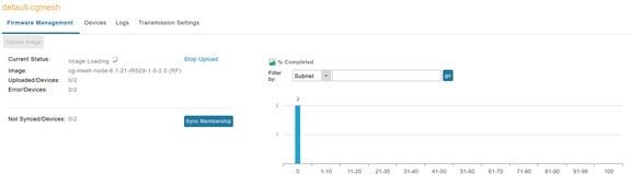
When you instruct IoT FND to upload a firmware image to the members of an RME firmware group or subnet, IoT FND pushes the
image to the group members in the background and tracks the upload progress to ensure that the devices receive the image.
A Resilient Mesh Endpoint (RME) stores three firmware images:
Uploaded image: Image most recently uploaded.
Running image: Image that is currently operational.
Backup image: It serves as a golden (fallback) image for the RME if there is an issue with the running image.
Note
You can initiate up to 3 firmware downloads simultaneously.
Note
IR500s and other RME devices can coexist on a network; however, for firmware management they cannot belong to the same group.
Note
RME devices can report BL/Boot Loader image types to IoT FND, but IoT FND cannot upload boot loader images to devices.
Actions Supported and Information Displayed at the Firmware Management Pane
At the Firmware Management pane, you can filter the display by Subnet, PanID or Group when you are in the Devices tab.
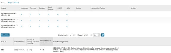
For every image in the list, IoT FND displays the information as noted in the table:
Table 1. Image Information Displayed by IoT FND
Item
Description
Image
Image name.
Uploaded
Specifies the number of devices that uploaded the image. Click the number to display a list of these devices.
Running
Specifies the number of devices running this image. Click the number to display a list of these devices.
Backup
Specifies the number of devices using this image as a backup. Click the number to display a list of these devices.
Boot Loader
Specifies the boot loader image version.
LMAC
Specifies the LMAC image version.
BBU
Specifies the BBU image version.
Status
Specifies the status of the upload process.
Scheduled Reload
Specifies the scheduled reload time.
Actions
Provides two actions:
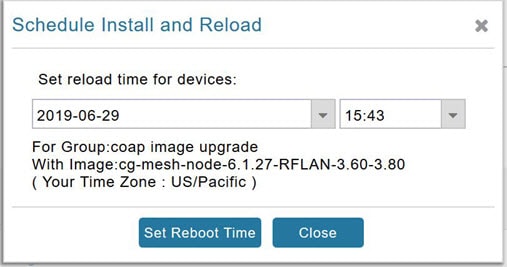
Schedule Install and Reload —Schedule the installation date and time of the loaded image and the reboot of the endpoint by
selecting the Calendar icon.
Set as Backup —Set the firmware backup image by selecting the clock icon with reverse arrow.
Click the Set as Backup button. (See the icon in the Actions summary in Table 1).
Step 2
Click Yes to confirm backup.
Setting the Installation Schedule
To set the installation schedule for an image:
Procedure
Step 1
Click the Schedule Install and Reload button (Calendar icon). For more information, see Table 1.
The following message appears if you try to schedule a reload operation for the node that is scheduled for stack switch operation.
Step 2
In the page that appears, specify the date and time for the installation of the image and rebooting of device.
Figure 1. Schedule and Install and Reload Page
Step 3
Click the Set Reboot Time button.
Firmware Update Transmission Settings
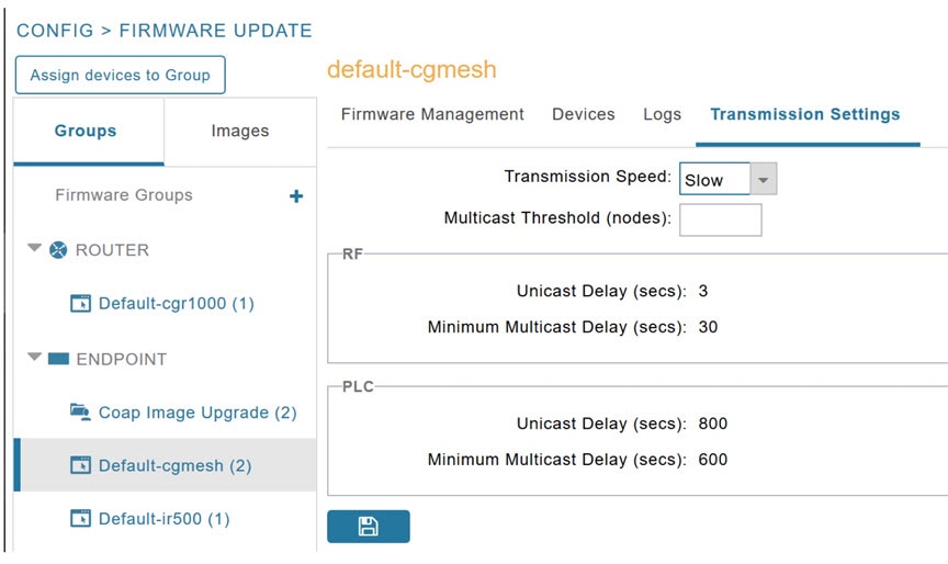
You can configure the Transmission Speed for pacing mesh firmware downloads at the Transmission Settings tab (See CONFIG > FIRMWARE UPDATE page).
Procedure
Step 1
Select the Transmission Speed. Options are Slow (default), Medium, Fast or Custom.
The Slow setting is recommended as the initial setting. You can increase the Slow setting to Medium (or even Fast) if the
following conditions exist:
The slow setting does not cause any issues in the database and it is able to handle the workload presented without raising
any alarms.
There is a need to improve on the time taken to do the firmware download.
Step 2
Configure the minimum number of nodes necessary to enable the Multicast firmware upload.
Note
For Custom Transmission Speed, you will have to specify Multicast Threshold, Unicast Delay and Minimum Multicast Delay values.
Refer to the table below for the definitions of the terms on the CONFIG > FIRMWARE UPDATE > Transmissions Settings page.
Figure 2. CONFIG > FIRMWARE UPDATE
Table 2. Definitions of variables seen on CONFIG > FIRMWARE UPDATE Transmissions Settings page
Item
Description
Minimum Multicast Delay (seconds)
Time between subsequent blocks when sending multi-cast messages/blocks/packets to a node.
Multicast Threshold (nodes)
Minimum number of nodes needed to ensure that a multicast transmission can happen in a subnet, if the number of elements requiring
a specific image block is greater than or equal to the multicast-threshold value.
Transmission Speed
Options are Slow (default), Medium, Fast or Custom.
Unicast Delay (seconds)
Time between subsequent blocks when sending unicast messages, blocks or packets to a node.
Uploading a Firmware Image to a Resilient Mesh Endpoint (RME) Group
To upload a firmware image to mesh endpoint group members:
Procedure
Step 1
Choose CONFIG > FIRMWARE UPDATE.
Step 2
Click the Groups tab (left-pane).
Step 3
Select the Endpoint firmware group to update.
Step 4
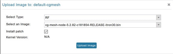
In the right panel, select Firmware Management and then click the Upload Image button. In the entry panel that appears, do
the following:
From the Select Type drop-down menu, choose the firmware type for your device.
From the Select an Image drop-down menu, choose the firmware bundle to upload.
AP800 Firmware Upgrade During Zero Touch Deployment
During the PnP bootstrapping, whenever an access point (AP) or router sends the firmware request, FND will need to make the
choice as to whether Unified Firmware or Autonomous Firmware is updated on the AP to make it accessible to the Cisco Wireless
LAN Controller (WLC) after a firmware upgrade.
Note
Once you set up the DHCP server on a Cisco IOS router, WLC generally handles the software updates for the AP.
Allows you to set the desired firmware that will update an IR829 router during ZTD.
There are two possible firmware options:
Option 1: Set the ‘unified’ version (k9w8: the factory-shipped version) as the desired firmware.
Option 2 : Set the autonomous firmware as the desired firmware version.
During the ZTD process, the firmware upgrade of an access point (AP) or embedded AP on an IR829 router will upgrade using
the firmware version you define as the autonomous firmware.
To define the Autonomous Firmware for an IR829 router:
Procedure
Step 1
Choose CONFIG > DEVICE CONFIGURATION.
Step 2
Select the desired router: Default-ir800 (left-pane).
Step 3
Check the installed firmware version, BEFORE upload. if equal to the latest version, skip firmware upgrade.
Step 4
Before you upload the software to the router, check the image and version:
If the router image version is equal to the latest version, skip upgrade.
If router image has the latest
Step 5
Select Edit AP Configuration Template tab (right-pane).
Step 6
Enter the following text in the right-pane:
ip dhcp pool embedded-ap-pool
network <router_ip> 255.255.255.0
dns-server <dns_ip>
default-router <router_ip>
option 43 hex f104.0a0a.0a0f (Note: Enter a single WLC IP
address(10.10.10.15) in hex format)
ip address <router_ip> 255.255.255.0
! {Note the symbol in this line is an exclamation point}
service-module wlan-ap 0 bootimage unified
Step 7
Click disk icon (bottom of page) to save the commands in the configuration template.
Image Diff Files for IR809 and IR829
To reduce the file size that transfers across network for IR809 and IR829, you can send a partial image:
At the Upload Image page, select type: IOS-IR800.
Check box for option: “install patch for IOS and hypervisor from this bundle.”
Gateway Firmware Updates
IC3000 Firmware Updates:
At the CONFIG > FIRMWARE UPDATE page, you can add or delete the IC3000 firmware image.
Note
Firmware image upload depends on interface speeds. You can set the timeout duration (in minutes) for firmware upload in cgms.properties
file using "igma-idle-timeout" key. If you don’t set this duration, then default timeout duration will be 15 minutes.
At the Images tab page, expand the Gateway icon and click on IC3000 to see a list of available IC3000 images.
Configuring Firmware Group Settings
This section describes how to add, delete, and configure firmware groups, and includes the following topics:
Upload operations only begin when you click the Resume button.
When you add routers or RMEs to IoT FND, the application sorts the devices into the corresponding default firmware group:
default-<router> or default-cgmesh. Use these groups to upload and install firmware images on member devices. Add firmware groups to manage
custom sets of devices. You can assign devices to firmware groups manually or in bulk. Before deleting a firmware group, you
must move all devices in the group to another group. You cannot delete non-empty groups.
When creating firmware groups note the guidelines:
CGRs, IR800s can coexist on a network; however, for firmware management, they cannot belong to the same firmware group.
IR500s and other RMEs devices can coexist on a network; however, for firmware management, they cannot belong to the same
group.
The Groups tab on the CONFIG > FIRMWARE UPDATE page displays various device metrics.
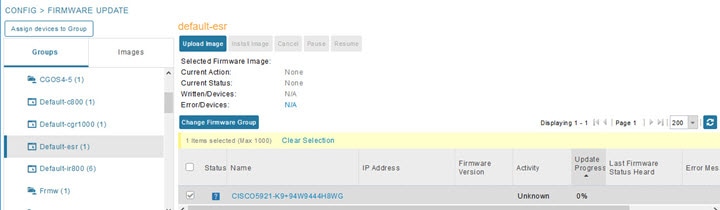
Figure 8. CONFIG > FIRMWARE UPDATE
Tip
At the Firmware Update page, click the Error/Devices link (not shown) in the Firmware Update page to apply a filter.
Click Clear Filter to revert to an unfiltered view of the selected device group.
Adding Firmware Groups
To add a firmware group:
Procedure
Step 1
Choose CONFIG > FIRMWARE UPDATE.
Step 2
Click the Groups tab.
Step 3
In the Groups pane, select one of the following:
Default-cgr1000
Default-ir500
Default-ir800
Default-cgmesh
Step 4
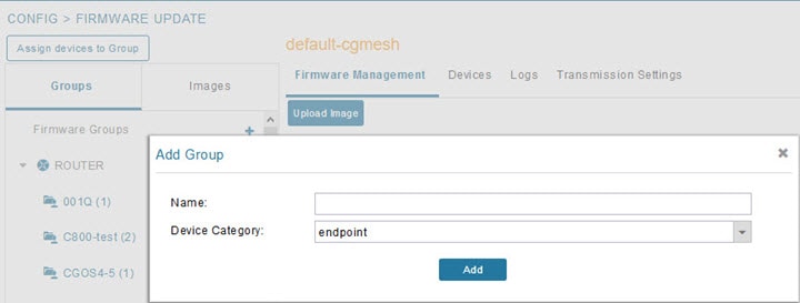
Click + next to Firmware Groups heading in the Groups pane to Add Group.
Step 5
In the Add Group dialog box, enter the name of the firmware group. Device Category options depend on the device type you select in Step 3.
Step 6
Click Add.
The new group label appears under the corresponding device type in the Firmware Groups pane.
Click the Assign devices to Firmware Group button (found above the Groups tab).
Step 5
In the window that appears, click Browse and locate the device list CSV or XML file.
Step 6
From the Group drop-down menu, choose the destination group.
Step 7
Click Assign to Group.
Note
IoT FND moves the devices listed in the file from their current group to the destination group.
Step 8
Click Close.
Moving Devices to Another Group Manually
To manually move devices to a group:
Procedure
Step 1
Choose CONFIG > FIRMWARE UPDATE.
Step 2
Click the Groups tab.
Step 3
In the Firmware Groups pane, select the desired firmware group based on device type.
Note
If this is an ENDPOINT firmware group, click the Devices tab above the main pane.
Step 4
Check the check boxes of the devices that you want to move.
Step 5
Click Change Firmware Group to open a pop up window.
Step 6
From the Firmware Group drop-down menu, choose the firmware group to which you want to move the devices or enter a new group name.
Step 7
Click Change Firmware Group.
Step 8
Click Close.
Renaming a Firmware Group
In the Firmware Update page, there are two firmware groups available, namely user-created groups and default groups of router, endpoint, or gateway.
IoT FND allows you to rename the user-created firmware groups only. You cannot rename the default firmware groups.
To rename a firmware group:
Procedure
Step 1
Choose CONFIG > FIRMWARE UPDATE.
Step 2
Click the Groups tab.
Step 3
In the Firmware Groups pane, select the firmware group to rename.
Step 4
Move the cursor over the firmware group and click the Edit Group Name pencil icon.
Note
Starting with IoT FND, you can only rename the user-created firmware groups and you cannot rename the default firmware groups.
The pencil icon does not appear for the default firmware groups.
Step 5
In the Rename Group window, enter the new name and then click OK.
Note
When you enter an invalid character entry (such as, @, #, !, or +) within the Rename Group field, IoT FND displays a red alert
icon, highlights the field in red, and disables the OK button.
Deleting Firmware Groups
Note
Before deleting a firmware group, you must move all devices in the group to another group. You cannot delete non-empty groups.
To delete a firmware group:
Procedure
Step 1
Choose CONFIG > FIRMWARE UPDATE.
Step 2
Click the Groups tab.
Step 3
In the Firmware Groups pane, select a firmware group to display a list of all possible firmware images for that group in the
right pane.
Step 4
Check the box next to the firmware group that you want to delete.
Step 5
Click Clear Selection that appears above the entry (yellow bar).
Step 6
To confirm deletion, click Yes.
Step 7
Click OK.
Firmware images
Firmware images in Cisco IoT FND are software files that you use to update and enhance the firmware of managed Cisco IoT devices.
A router group in Cisco IoT FND is a collection of routers that you can organize together to simplify managing, monitoring,
and configuring tasks across multiple routers simultaneously.
Table 4. Feature history
Feature name
Release information
Description
Add firmware images
Import the firmware file into the Cisco IoT FND database so it can be managed and later deployed to Cisco IoT routers.
Here are the steps to add firmware images to Cisco IoT FND:
Procedure
Step 1
In the Cisco IoT FND menubar, choose CONFIG > Firmware Update.
Step 2
Click the Images tab.
Step 3
Select ROUTER or ENDPOINT or GATEWAY and then select a device group. For example, IOS-XE-IR1100.
Step 4
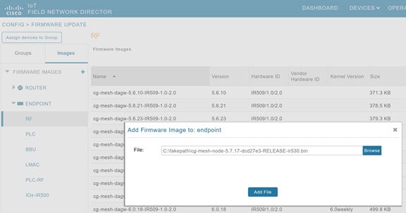
Click the + icon adjacent to FIRMWARE IMAGES.
Step 5
Click Browse to locate the firmware image. Select the image, then click Add File.
The image appears in the Firmware Images list.
What to do next
Upload firmware images
Upload firmware images
This task guides you to upload firmware images to a router group, Cisco IoT FND pushes the image to the router group in the
background and tracks the upload progress to ensure that the devices receive the firmware image.
Here are the steps to upgrade firmware on a router group:
Before you begin
Firmware image upload and installation require the following free disk space:
For bundle boot mode: 20 MB + uploaded file size
For install boot mode: 800 MB + uploaded file size
If any devices in the router group encounter errors during firmware upload, Cisco IoT FND prevents firmware installation and
you can see an error message indicating the presence of errored devices. For errored or cancelled devices, move them to a
separate install group and repeat the upload and installation process.
If you cancel the firmware upload for some devices, firmware installation proceeds only on devices that successfully completed
the upload. For errored or cancelled devices, move them to a separate install group and repeat the upload and installation
process.
Procedure
Step 1
In the Cisco IoT FND menubar, choose CONFIG > Firmware Update.
Step 2
Click the Groups tab.
Step 3
Select the router group that you want to upgrade.
Step 4
Click Upload Image.
Step 5
The Select Type: drop-down list is auto-selected based on the selected router group.
Step 6
Select an image from the Select an Image drop-down list.
Step 7
Click Upload Image Now to initiate the firmware upgrade process instantly.
Note
Use the Cancel or Pause buttons to either cancel or pause the firmware image upload.
What to do next
Install firmware images.
Install firmware images
Use this task to install a firmware image to a router group after you upload a firmware image to Cisco IoT FND.
Before you begin
If you cancel the firmware upload for some devices, firmware installation proceeds only on devices that successfully completed
the upload. For errored or cancelled devices, move them to a separate install group and repeat the upload and installation
process.
Procedure
Step 1
In the Cisco IoT FND menubar, choose CONFIG > Firmware Update.
Step 2
Click the Groups tab.
Step 3
In the Groups tab, select the router group for which you want to install the firmware.
Step 4
Click Install Image.
Step 5
In the Install Image to: dialog box, select Install Image Now to install the image instantly.
Step 6
Use the Cancel or Pause buttons to cancel or pause the firmware installation.
Note
If you restart Cisco IoT FND during the image installation process, it automatically resumes any firmware installations that
were in progress before going offline.
The firmware installation operation can time out on some routers. During installation, a job scheduler runs every two hours
to terminate any firmware install jobs that are stuck at 35% progress. You can adjust the scheduler’s default interval by
setting the "firmware-install-timeout-schedule-cron-hour" key in the cgms.properties file to any value greater than 0 and
less than 24. This scheduler applies only to jobs stalled at the 35% mark.
When a firmware install or image upload operation for routers takes too long, it can cause other jobs in the queue to wait
longer. You can set the timeout duration for stuck firmware jobs using the router-firmware-upload-timeout-minutes and router-firmware-install-timeout-minutes keys in the cgms.properties file; the default is 8 hours (480 minutes).
What to do next
View the firmware images
View firmware images
Use the following instructions to view the firmware images on Cisco IoT FND:
Procedure
Step 1
From the Cisco IoT FND menubar, choose CONFIG > FIRMWARE UPDATE.
Step 2
Click the Images tab.
Step 3
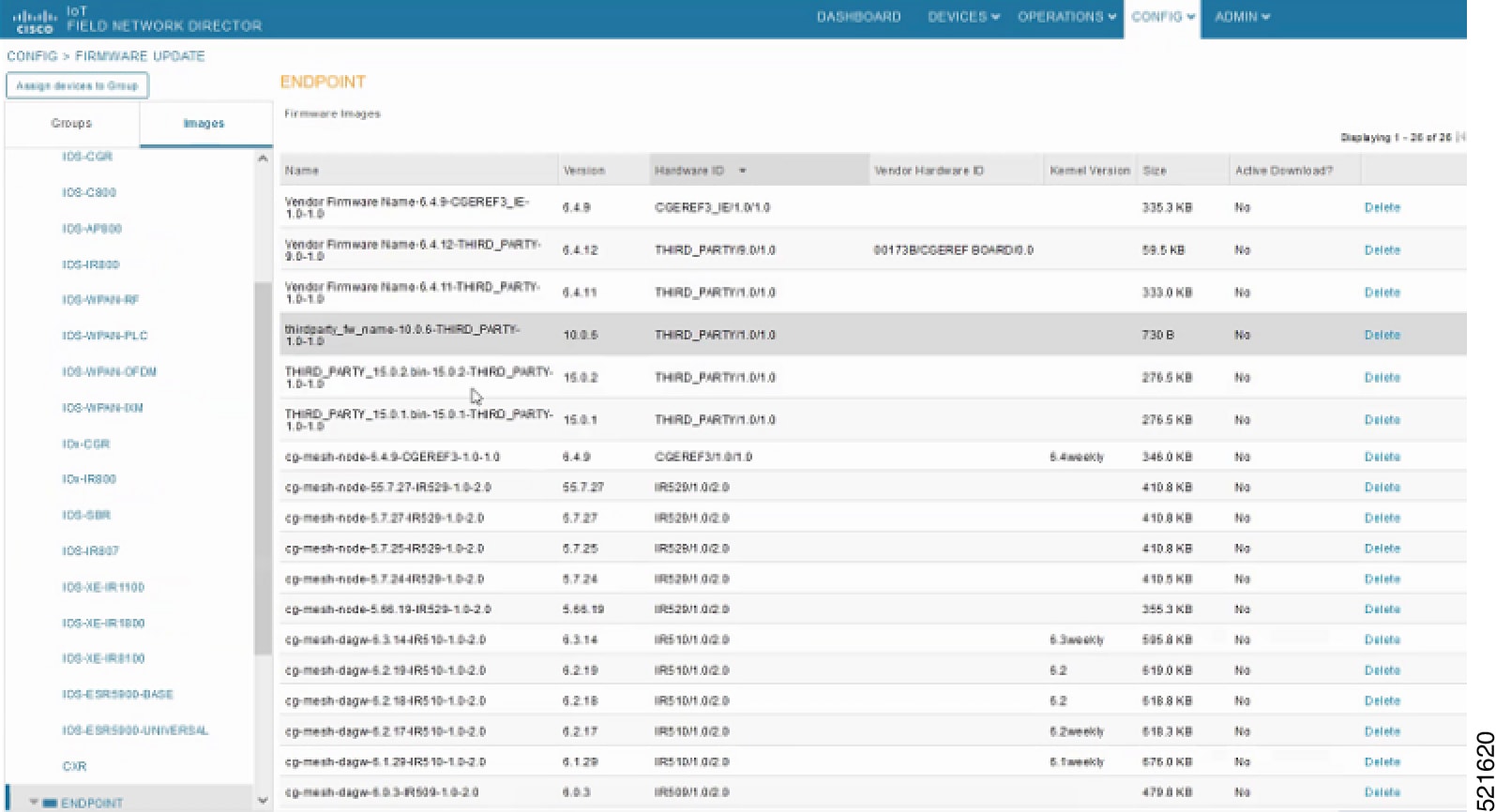
Select a ROUTER or an ENDPOINT to display all firmware images for those devices in the Cisco IoT FND database.
You can view a list of firware images associated with the particular device type. You can view details such as name, version,
hardware ID, vendor hardware ID, size, active download etc.
Step 4
Click Delete to delete a particular firmware image.
Push StackMode
Starting from Cisco IoT FND Release 4.8.1, Cisco IoT FND supports multiple mesh networking modes for IoT deployments. You
must be an admin or you should have firmware upgrade permission to perform the switch from CR-Mesh to Wi-SUN stack mode. Switching
from CR-Mesh to Wi-Sun mode changes the underlying radio protocol used by devices in the network. CG-Mesh is Cisco mesh technology,
while Wi-Sun leverages the IEEE 802.15.4g standard with Wi-SUN profiles for interoperability within a broader ecosystem. During
the switching process, a single or multiple PAN nodes are grouped and scheduled for switching devices from CG-Mesh to Wi-SUN
stack. Wi-SUN stack supports both unicast and multicast transmissions. For more information see, Mesh protocol modes.
Supported Platforms
Cisco IoT FND supports the following platforms for switching devices from CG-Mesh to Wi-SUN stack:
ITRON30
CR-Mesh
Cisco 500 Series WPAN Industrial Routers
Table 5. Feature History
Feature Name
Release Information
Description
Support For Wi-SUN Stack Switch
Cisco IoT FND Release 4.8.1
Switch devices from CR-Mesh to Wi-SUN StackMode.
Prerequisites
Here are the prequisites for switching to Wi-SUN mode from CR-Mesh mode using Cisco IoT FND:
Ensure that the following supported devices are running the minimum required versions
Cisco CGR: Cisco IOS Release 15.9(3)M1 and later releases.
Cisco IR8140: Cisco IOS-XE 17.x and later releases.
Once you are done with switching of the devices from CR-Mesh to Wi-SUN stack mode, ensure to update the WPAN OFDM/FSK stack
mode to Wi-SUN stack. If the WPAN OFDM/FSK is not updated, the node can't join back the network and will move to Down state in Cisco IoT FND.
Switch from CR-Mesh to Wi-SUN StackMode
You can push your devices to Wi-SUN mode from CR-Mesh mode by scheduling the task at your convenience.
Configure Push StackMode
Here are the instructions to push devices to Wi-SUN stack mode:
Procedure
Step 1
From the Cisco IoT FND menubar, choose CONFIG > Firmware Update.
Step 2
Click the Groups tab in the left pane.
Step 3
Select the default or user-defined firmware group from the ENDPOINT.
Step 4
Check the PAN ID check box in the StackMode Switch table.
Step 5
Click Push StackMode to set your device mode to Wi-SUN stack mode.
Step 6
A confirmation dialog-box appears, click Yes. If you see a stack mode failure message, retry pushing to StackMode.
Step 7
Based on the status of the push stack mode process, the following states are displayed for the selected PAN ID in the StackMode Switch table:
Field
Description
Stack Operation Type
Displays the following states for the Push StackMode operation:
StackMode Push Initiated: Displays initiation of the stack mode operation.
StackMode Push Completed: Displays the completion of the stack mode operation.
No operation when no operation is initiated.
Stack Operation Status
Displays the overall success and failure status of the devices for the selected PAN during the StackMode operation.
Job Status
Displays the following statuses:
In-progress
Success
Aborted
Your device modes are set to Wi-SUN stack mode.
Schedule Push StackMode Time
Here are steps to configure Push StackMode Time:
Procedure
Step 1
From Cisco IoT FND menubar, choose CONFIG > Firmware Update.
Step 2
From the StackMode Switch table, check the PAN ID check box.
Note
You can select only the PAN ID that has successfully completed the push StackMode configuration.
Step 3
Click Push StackMode Time.
A Confirm dialog box appears to schedule the switching initiation process for moving CR-Mesh devices to Wi-SUN stack.
Based on the status of the StackMode time process, the following states are displayed for the selected PAN ID in the StackMode Switch table.
Table 6. PAN ID Status
Field
Description
Stack Operation Type
Displays the following states for the Push StackMode operation:
StackMode Switch Time Push Initiated : Displays initiation of the stack mode schedule operation.
StackMode Switch Time Completed: Displays the completion of the stack mode schedule operation.
Stack Operation Status
Displays the overall success and failure status of the devices for the selected PAN during the StackMode operation.
Job Status
Displays the following statuses:
In-progress
Success
Aborted
Note
If you abort an in-progress Push StackMode Time job, the job stops immediately and retains all progress completed before the
abort. To complete Push StackMode Time for the remaining devices, run Push StackMode Time again to restart the workflow.
When you run Push StackMode Time again for an aborted or unsuccessful workflow, Cisco IoT FND sends requests only to the pending
devices. It ignores devices that successfully received the Push StackMode Time request during the previous run.
When you perform Push StackMode Time more than once on a workflow, the timestamp on devices in the same PAN might vary depending
on the time configured in each run. We recommend that you push the same timestamp each time. If different timestamps are configured
across devices in the same PAN, the devices switch to Wi-SUN mode according to their configured time, which might prevent
some nodes from rejoining the network.
If you want to reschedule the Push StackMode Time and set the same for all devices in the same PAN ID, we recommend that you
cancel Push StackMode and run Push StackMode and Time as a fresh workflow.
Step 4
Select the time and date in the Schedule Switch Wi-SUN Stack dialog box and click Schedule .
Note
Ensure that the scheduled time is not more than 49 days from the current date.
Note
If the scheduled time is in the past, an error message appears.
Step 5
Click Yes to confirm the stack switching operation.
On confirming the stack switching process, the stack operation type gets updated to Stack Switch Time Push Initiated state for the selected PAN ID.
Step 6
Click OK in the Success dialog box.
On successful completion of the stack switch process, the stack operation type column in the table gets updated to Stack Switch Time Push Completed state for the selected PAN ID.
Note
We recommend that you wait until all the devices in the selected PAN get switched to Wi-SUN stack, as there is a possibility
of some devices failing to switch in the scheduled time. However, the failed devices automatically switch to Wi-SUN StackMode
after a one-day time period.
If you don't schedule Push Stack Mode Time after you Push StackMode, the endpoint devices switch to Wi-SUN mode after 24 hours.
Note
If you want to reschedule the stack time for some reason, then you have to cancel the current stack switch operation, push
the StackMode again, and reinitiate the scheduling stack switch process.
Cancel Wi-SUN Stack Switch Operation
Here are the steps to cancel Wi-SUN stack switch operation:
Before you begin
Starting from Cisco IoT FND Release 5.1.2, use the cancel switch operation during any stage of the Push StackMode workflow.
Cancel switch operation cancels the scheduled Push StackMode workflow as well.
Procedure
Step 1
From the Cisco IoT FND menubar, Choose CONFIG > Firmware Update.
Step 2
In the Firmware Management page, check the PAN ID check box for which you have completed either configuration or scheduling operation.
Step 3
Click Cancel StackMode.
Based on the status of the StackMode cancellation process, the following states are displayed for the selected PAN ID in the
StackMode Switch table.
Table 7. PAN ID Status
Field
Description
Stack Operation Type
Displays the following states for the Push StackMode operation:
StackMode Cancel Initiated: Displays the intitiation of cancelling the StackMode operation.
StackMode Cancel Completed: Displays the completion of cancelling the StackMode Operation.
Stack Operation Status
Displays the overall success and failure status of the devices for the selected PAN during the StackMode operation.
Job Status
Displays the following statuses:
In-progress
Success
Aborted
Step 4
Click Yes to cancel the stack switch operation.
A Success dialog box appears to indicate the successful cancellation of the Wi-SUN stack switch operation.
Validate Push StackMode
In the StackMode Push Initiated state, the devices in the selected PAN ID are validated based on the following parameters:
Firmware version
StackMode configuration
Table 8. Push StackMode Validation
Scenarios
System Validation
User Action
Firmware version 6.2 MR.
Checks if the devices in the selected PAN ID are running firmware version 6.2 MR.
If the firmware version is lower than 6.2 MR, then an error message appears.
Note
for more information on the devices that are running a lower version go to the Devices tab.
You must upgrade the devices to firmware version 6.2 MR or later versions.
After upgrading the devices, you must again push new StackMode for the selected PAN ID.
If the firmware version is greater than 6.2 MR, then the devices are already in Wi-SUN stack.
StackMode configuration.
Checks if all devices in the selected PAN ID received the StackMode configuration.
Some devices in the selected PAN ID fail to receive the configuration.
Push StackMode again for the selected PAN ID.
or
Remove the devices that are in Down state from FND and again push StackMode for the remaining devices in the PAN ID.
If all the devices in the selected PAN ID received the StackMode configuration, then you can schedule the devices for stack
switch operation initiation.
You can schedule the devices for Wi-SUN stack switch only on successful completion of pushing StackMode configuration to all
devices in the selected PAN.
Note
On successful completion of the validation, the stack operation state for the selected PAN ID changes to Stack Mode Push Completed.
View StackMode information
From the Devices tab, you can view the StackMode status and StackMode time of each device for the following processes:
Pushing Devices to Wi-SUN StackMode
Scheduling Devices for Wi-SUN Stack Switch
Canceling Wi-SUN Stack Switch Operation
Procedure
Step 1
From the Cisco IoT FND menubar, choose CONFIG > FIRMWARE UPDATE > Groups tab.
Step 2
Select the default or user-defined firmware group from the ENDPOINT.
Step 3
Select the PAN ID from the StackMode Switch table.
Step 4
Click the Devices tab.
The Stack Change Status column displays the following states:
Table 9. Device State
Device State
Description
Not Started
Indicates the supported devices that are not initiated for Wi-SUN stack switch.
Not Applicable
Indicates the devices that are not supported for Wi-SUN stack switch.
Configuring StackMode
Indicates the devices that are pushed for StackMode operation.
Configured Stackmode
Indicates the devices that are successfully configured with StackMode.
Scheduling Stackmode time
Indicates the devices that are scheduled for StackMode switch.
Success
Indicates the devices that are successfully switched from CG-Mesh to Wi-SUN stack.
Canceling stackmode switch
Indicates the devices that are scheduled for canceling StackMode switch.
Cancelled stackmode switch
Indicates the devices that are successfully cancelled from switching to Wi-SUN stack.
Filtering Options
Click Show Filter. The page displays three drop-down lists.
Select the search option from the first drop-down list. For example, if you select Status from the first drop-down list, the
available list of states appears in the third drop-down list.
Select the required option in the third drop-down list and click +.
Your selection is displayed in the text box above the drop-down lists.
Click the search icon.
The table displays information based on the search criteria set by you.
View logs for Wi-SUN stack switch
To view logs for Wi-SUN stack switch:
Procedure
Step 1
From the Cisco IoT FND menubar, choose CONFIG > Firmware Update.
Step 2
Select the firmware group from the ENDPOINT in the left pane.
Step 3
In the Firmware Management page, select the PAN ID for which you want to see the logs.
Step 4
Click the Logs tab.
In the Logs page, you can view the events that are recorded for the selected PAN ID.
View Audit Trail for Wi-SUN stack switch
To view audit trail for Wi-SUN stack switch :
Procedure
Step 1
From the Cisco IoT FND menubar, choose ADMIN > System Management > Audit Trail.
Step 2
In the Audit Trail page, click the Date/Time drop-down arrow to filter the audit trail based on the date and time.
You can view the audit trail of the stack operations that were performed on the selected PAN ID.
Upgrading Firmware Image during Bootstrapping
During bootstrapping, you can enter a different image if the installed image at manufacturing is inappropriate. This is supported
for IR1800 and IR8100 devices from the versions 17.13.01 and above. Plug and Play (PnP) must be supported on these devices.
Note
Ensure that IR8100 device has the network-essentials license to register the device to IoT FND.
PnP Device Information service retrieves current firmware version on the device and the PnP ImageInstall service performs
the image installation. The CGNA ‘image-retrieve' service transfers the image file from IoT FND to router.
Procedure
Step 1
Set the firmware-update-bootstrap property in cgms.properties to ‘true’.
Step 2
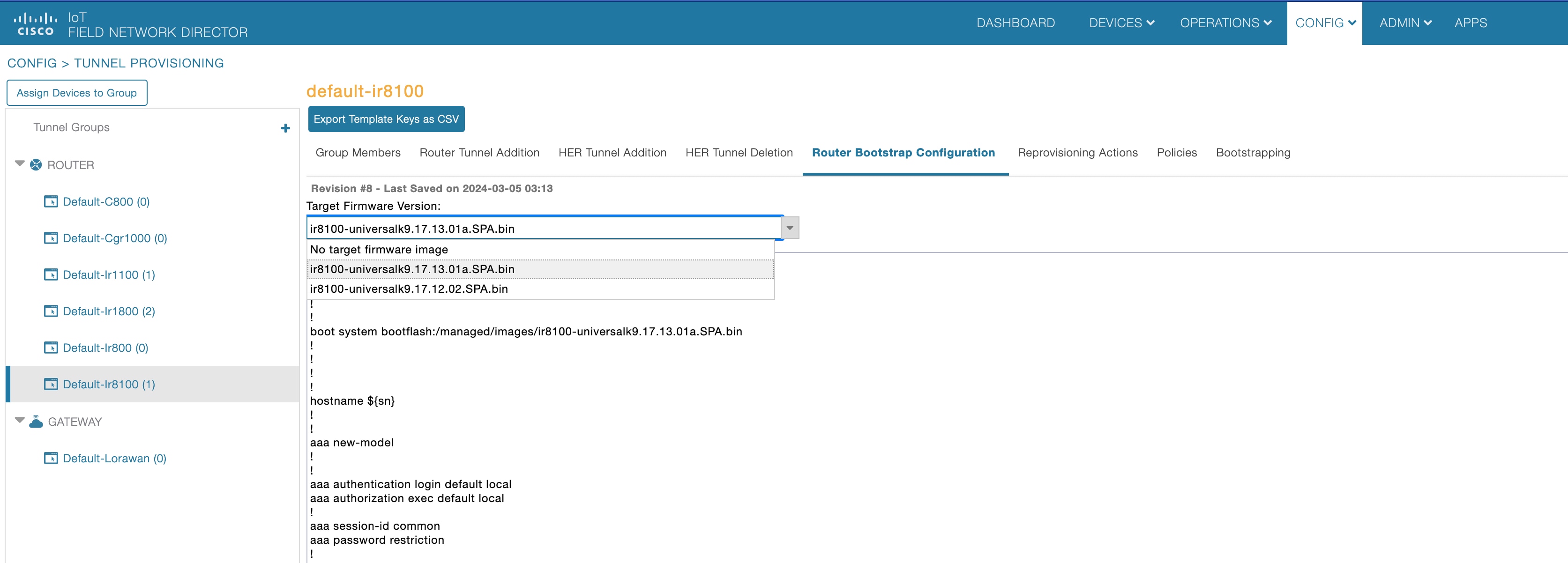
On the Tunnel Provisioning Page, navigate to CONFIG > TUNNEL PROVISIONING > ROUTER BOOTSTRAP CONFIGURATION.
Step 3
Select the device group in the left pane, choose the Target Firmware Version from the drop down that lists the images in IoT
FND, and click Save.
The PnP workflow configures the device to load the new image upon the next reload by executing the boot system command. The
configuration changes are saved on the device. The PnP reload happens and sends a message to the PnP server after which an
event is generated denoting image installation.
Note
The PnP workflow supports device upgrade only if the target image version is higher than the running (current) image version.
If the target image runs the same or lower version, then the device upgrade is skipped during the PnP workflow.
During PNP, you also have the option to skip the firmware upgrade and proceed with PNP if the source operating system on these
devices is found to be unreliable. Enter the image versions as comma separated values in pnp-skip-update-ios-xe-fw-versions property in cgms.properties file. This property is applicable for all IR1100, IR1800, and IR8100 devices. For more information,
see Skipping Firmware Upgrades during PNP.
Skipping Firmware Upgrades during PNP
During Zero Touch Deployment (ZTD), certain scenarios may arise where Plug-and-Play (PNP) devices come bundled with software
that exhibits instability or issues. If the source operating system (OS) on these devices is found to be unreliable, it can
potentially disrupt the entire registration process. In such instances, during the PNP process, you can skip the firmware
upgrade step while allowing PNP to proceed seamlessly. However, you can upgrade the firmware once the PNP process is complete.
To perform a PNP with firmware upgrade skip:
Procedure
Step 1
Set the image versions in pnp-skip-update-ir1100-fw-versions property in cgms.properties file.
Note
The pnp-skip-update-ir1100-fw-versions property is applicable for IOS-XE routers only.
Step 2
Set the image versions in pnp-skip-update-ios-xe-fw-versions property in cgms.properties file.
Note
The pnp-skip-update-ios-xe-fw-versions property is applicable for IOS-XE routers only.
Step 3
Choose CONFIG > Tunnel Provisioning. Select the router group for which you intend to execute the PNP process.
Step 4
Click Router Bootstrap Configuration tab.
Step 5
Under Target Firmware Version, specify the image version you want to skip and click Save.
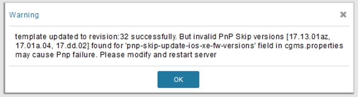
The template is saved. However upon performing PNP, during router bootstrap configuration, a warning popup appears if any
invalid entry is found. In that case, modify the field and restart server.
If firmware install is skipped during PnP process, the log details are stored in server.log file. The sample INFO log is shown
below:
Aug 03 2023 19:24:26.854 +0000: %IOTFND-6-UNSPECIFIED:
 %[ch=WorkResponseHandler][eid=IR1101-K9+FCW23500HJ3][ip=1.1.1.121]
[sev=INFO][tid=tunnelProvJetty-67]: Retrieved device image version
[17.9.3] is present in PnP firmware image skip list. Firmware image update
 during PnP process will be skipped.
Note
In order to upgrade the device with the latest firmware version, skip entering the current image version in cgms.properties
and proceed with PNP.
Step 6
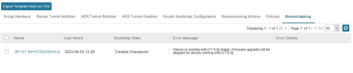
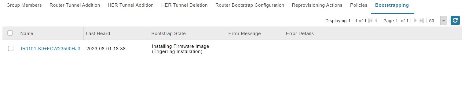
Navigate to the Bootstrapping tab where the Error Message field is updated though the PNP progresses as is.
The Bootstrapping tab shows the status of the PNP under the Bootstrap State field.





 Feedback