Contents
- Release Notes for Cisco ASR 9000 Series Aggregation Services Routers for Cisco IOS XR Software Release 5.1.11
- System Requirements
- Feature Set Table
- Memory Requirements
- Supported Hardware
- Software Compatibility
- Cisco ASR 9000 Series Aggregration Services Router Right-To-Use (RTU) Licensing
- Firmware Support
- Determining Your Software Version
- Software Features Introduced in Cisco IOS XR Software Release 5.1.11 for Cisco ASR 9000 Series Aggregation Service Router
- ACL Support in RPL Prefix Sets
- BGP Link-State
- BGP Multi-Instance Multi-AS Enhancement
- BGP Permanent Network
- OSPF IP Fast Reroute Loop Free Alternate
- RCMD Enchancements
- Advanced Satellite nV Topologies
- DHCP RADIUS Proxy
- Line Card Subscribers
- Routed Subscriber Sessions
- Static Sessions
- Subscriber Session Limit
- Subscriber Session-Restart
- GRE Tunnel Key
- MMRP for PBB VPLS Flood Optimization
- Dynamic Single Segment Pseudowire
- LFA over PW-HE
- PW-HE Ethernet Sub-interfaces and Interworking Interfaces (VC-type 11)
- Auto-IP
- DHCPv4 Local Server enhancements
- Carrier-Supporting-Carrier Support for MPLS LDP
- MPLS Static
- MPLS TE Extended Admin Groups
- MPLS TE IPv6 Autoroute
- MPLS TE SRLG Scale Enhancements
- MPLS TE Usability Enhancements
- Policy Based Forwarding
- PWHE over MPLS TE Tunnels
- Stateful Path Computation Element
- VRF Redirection to MPLS TE Tunnels
- Flow Aware QoS
- Inter-Class Policer Bucket Sharing
- QoS Offload on Satellite
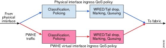
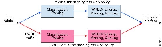
- QoS on Pseudowire Headend
- Multicast IRB
- LSP-switch for P2MP-TE
- Multicast support for PW-HE interfaces
- Two-Way Active Measurement Protocol (TWAMP)
- Software Feature Enhancements
- Hardware Features Introduced in Cisco IOS XR Software Release 5.1.1 for the Cisco ASR 9000 Series Router
- Important Notes
- Caveats
- Cisco IOS XR Caveats
- Caveats Specific to the Cisco ASR 9000 Series Aggregation Services Router
- Caveats Specific to the ASR 9001 Router
- Upgrading Cisco IOS XR Software
- Troubleshooting
- Resolving Upgrade File Issues
- Obtaining Documentation and Submitting a Service Request
Release Notes for Cisco ASR 9000 Series Aggregation Services Routers for Cisco IOS XR Software Release 5.1.11
Cisco IOS XR Software is a distributed operating system designed for continuous system operation combined with service flexibility and higher performance.
Note
For information on Cisco ASR 9000 Series Aggregation Services Router running Cisco IOS XR Software Release 5.1.11, see the Features Supported on the Cisco ASR 9000 Series Aggregation Services Router section.
These release notes describe the features provided on the Cisco ASR 9000 Series Aggregation Services Router running Cisco IOS XR Software Release 5.1.11 and are updated as needed.
For a list of software caveats that apply to the Cisco ASR 9000 Series Aggregation Services Router running Cisco IOS XR Software Release 5.1.11, see the Caveats section. The caveats are updated for every release and are described at http://www.cisco.com.
Cisco IOS XR Software running on the Cisco ASR 9000 Series Router provides the following features and benefits:
- IP and Routing—This supports a wide range of IPv4 and IPv6 services and routing protocols such as Border Gateway Protocol (BGP), Routing Information Protocol (RIPv2), Intermediate System-to-Intermediate System (IS-IS), Open Shortest Path First (OSPF), IP Multicast, Routing Policy Language (RPL), Hot Standby Router Protocol (HSRP), and Virtual Router Redundancy Protocol (VRRP) features.
- Ethernet Services—The following Ethernet features are supported:
- Ethernet Virtual Connections (EVCs)
- Flexible VLAN classification
- Flexible VLAN translation
- IEEE bridging
- IEEE 802.1s Multiple Spanning Tree (MST)
- MST Access Gateway
- L2VPN
- Virtual Private LAN Services (VPLS), Hierarchical VPLS (H-VPLS), Virtual Private Wire Service (VPWS), Ethernet over MPLS (EoMPLS), pseudo wire redundancy, and multi segment pseudo wire stitching.
- BGP Prefix Independent Convergence—This provides the ability to converge BGP routes within sub seconds instead of multiple seconds. The Forwarding Information Base (FIB) is updated, independent of a prefix, to converge multiple 100K BGP routes with the occurrence of a single failure. This convergence is applicable to both core and edge failures and with or without MPLS. This fast convergence innovation is unique to Cisco IOS XR Software.
- Multiprotocol Label Switching (MPLS)—This supports MPLS protocols, including Traffic Engineering (TE) [including TE-FRR and TW Preferred Path], Resource Reservation Protocol (RSVP), Label Distribution Protocol (LDP), Targeted LDP (T-LDP), Differentiated Services (DiffServ)-aware traffic engineering, and Layer 3 Virtual Private Network (L3VPN).
- Multicast—This provides comprehensive IP Multicast software including Source Specific Multicast (SSM) and Protocol Independent Multicast (PIM) in Sparse Mode only. The Cisco ASR 9000 Series Aggregation Services Router also supports Auto-Rendezvous Point (AutoRP), Multiprotocol BGP (MBGP), Multicast Source Discovery Protocol (MSDP), Internet Group Management Protocol Versions 2 and 3 (IGMPv2 and v3), IGMPv2 and v3 snooping, Multicast Listener Discovery (MLD) versions 1 and 2, and MLD snooping versions 1 and 2.
- Quality of Service (QOS)—This supports QoS mechanisms including policing, marking, queuing, random and hard traffic dropping, and shaping. Additionally, Cisco IOS XR supports modular QoS command-line interface (MQC). MQC is used to configure various QoS features on various Cisco platforms, including the Cisco ASR 9000 Series Aggregation Services Router. Supports the following:
- Manageability—This provides industry-standard management interfaces including modular command-line interface (CLI), Simple Network Management Protocol (SNMP), and native Extensible Markup Language (XML) interfaces. Includes a comprehensive set of Syslog messages.
- Security—This provides comprehensive network security features including Layer 2 and Layer 3 access control lists (ACLs); routing authentications; Authentication, Authorization, and Accounting (AAA)/Terminal Access Controller Access Control System (TACACS+), Secure Shell (SSH), Management Plane Protection (MPP) for management plane security, and Simple Network Management Protocol version3 (SNMPv3). Control plane protections integrated into line card Application-Specific Integrated Circuits (ASICs) include Generalized TTL Security Mechanism (GTSM), RFC 3682, and Dynamic Control Plane Protection (DCPP).
- Availability—This supports rich availability features such as fault containment, fault tolerance, fast switchover, link aggregation, nonstop routing for ISIS, LDP and OSPF, and nonstop forwarding (NSF).
- Enhanced core competencies:
- System Requirements
- Determining Your Software Version
- Software Features Introduced in Cisco IOS XR Software Release 5.1.11 for Cisco ASR 9000 Series Aggregation Service Router
- Hardware Features Introduced in Cisco IOS XR Software Release 5.1.1 for the Cisco ASR 9000 Series Router
- Important Notes
- Caveats
- Upgrading Cisco IOS XR Software
- Troubleshooting
- Obtaining Documentation and Submitting a Service Request
System Requirements
This section describes the system requirements for Cisco ASR 9000 Series Aggregation Services Router Software Release .
To determine the software versions or levels of your current system, see the Determining Your Software Version section.
- Feature Set Table
- Memory Requirements
- Supported Hardware
- Software Compatibility
- Cisco ASR 9000 Series Aggregration Services Router Right-To-Use (RTU) Licensing
- Firmware Support
Feature Set Table
The Cisco ASR 9000 Series Aggregation Services Router Software is packaged in feature sets (also called software images). Each feature set contains a specific set of Cisco ASR 9000 Series Aggregation Services Router Software Release 5.1.11.
This table lists the Cisco ASR 9000 Series Aggregation Services Router Software feature set matrix (PX PIE files) and associated filenames available for the Release 5.1.11 supported on the Cisco ASR 9000 Series Aggregation Services Router.
Table 1 Cisco IOS XR Software Release 5.1.11 PX PIE Files Feature Set
Filename
Description
Composite Package
Cisco IOS XR IP Unicast Routing Core Bundle
asr9k-mini-px.pie-5.1.11
Contains the required core packages, including OS, Admin, Base, Forwarding, Modular Services Card, Routing, SNMP Agent, and Alarm Correlation.
Cisco IOS XR IP Unicast Routing Core Bundle
asr9k-mini-px.vm-5.1.11
Contains the required core packages including OS, Admin, Base, Forwarding, Forwarding Processor Card 40G, Routing, SNMP Agent, Diagnostic Utilities, and Alarm Correlation.
Optional Individual Packages (Packages are installed individually)
Cisco IOS XR Manageability Package
asr9k-mgbl-px.pie-5.1.11
CORBA2 agent, XML3 Parser, and HTTP server packages. This PIE also contains some SNMP MIB infrastructure. Certain MIBs won't work if this PIE is not installed.
Cisco IOS XR MPLS Package
asr9k-mpls-px.pie-5.1.11
MPLS Traffic Engineering (MPLS-TE), Label Distribution Protocol (LDP), MPLS Forwarding, MPLS Operations, Administration, and Maintenance (OAM), Link Manager Protocol (LMP), Optical User Network Interface (OUNI), Resource Reservation Protocol (RSVP), and Layer-3 VPN.
Cisco IOS XR Multicast Package
asr9k-mcast-px.pie-5.1.11
Multicast Routing Protocols (PIM, Multicast Source Discovery Protocol [MSDP], Internet Group Management Protocol [IGMP], Auto-RP), Tools (SAP, MTrace), and Infrastructure [(Multicast Routing Information Base [MRIB], Multicast-Unicast RIB [MURIB], Multicast forwarding [MFWD]), and Bidirectional Protocol Independent Multicast (BIDIR-PIM).
Cisco IOS XR Advanced Video Package
asr9k-video-px.pie-5.1.11
Firmware for the advanced video feature for Cisco ASR 9000 Series Router chassis.
Cisco IOS XR Optics Package
asr9k-optic-px.pie-5.1.11
Firmware for the optics feature for Cisco ASR 9000 Series Aggregation Services Router Chassis. It enables Transport / OTN feature under interfaces.
Cisco IOS XR FPD Package
asr9k-fpd-px.pie-5.1.11
Firmware pie for all LC and RSP FPGAs and ASICs.
Cisco IOS XR Documentation Package
asr9k-doc-px.pie-5.1.11
.man pages for Cisco IOS XR Software on the Cisco ASR 9000 Series Aggregation Services Router Chassis.
Cisco IOS XR Services Package
asr9k-services-px.pie-5.1.11
Includes binaries to support CGv6 on ISM.
Cisco IOS XR Satellite Package - ASR9000v
asr9000v-nV-px.pie-5.1.11
Includes binaries to support Cisco ASR9000v Series Router Software and to support Cisco ASR 9000v Series Router as a satellite for Cisco ASR 9000 Series Router.
Cisco IOS XR BNG Package
asr9k-bng-px.pie-5.1.11
Includes binaries to support BNG features.
Cisco IOS XR Lawful Intercept (LI) Package
asr9k-li-px.pie-5.1.11
Includes LI software images.
Cisco IOS XR Satellite Package - ASR903
asr9k-asr903-nV-px.pie-5.1.11
Includes binaries to support Cisco ASR 903 Series Router software and to support Cisco ASR 903 Series Router as a satellite for Cisco ASR 9000 Series Router.
Cisco IOS XR Satellite Package - ASR901
asr9k-asr901-nV-px.pie-5.1.11
Includes binaries to support Cisco ASR 901 Series Router software and to support Cisco ASR 901 Series Router as a satellite for Cisco ASR 9000 Series Router.
Cisco IOS XR Security Package
asr9k-k9sec-px.pie-5.1.11
Support for Encryption, Decryption, IP Security (IPSec), Secure Shell (SSH), Secure Socket Layer (SSL), and Public-key infrastructure (PKI) (IPSec is supported only for OSPFv3).
This table lists the Cisco ASR 9000 Series Aggregation Services Router TAR files.Memory Requirements
Caution
If you remove the media in which the software image or configuration is stored, the router may become unstable and fail.
The minimum memory requirements for Cisco ASR 9000 Series Aggregation Services Router running Cisco IOS XR Software Release 5.1.11 consist of the following:
- minimum 6 GB memory on the RSP-440, and ASR9922 RP [A9K-RSP-4G and A9K-RSP-8G is 4 GB]
- maximum 12 GB memory on the RSP-440, and ASR9922 RP [A9K-RSP-4G and A9K-RSP-8G is 8 GB]
- minimum 2 GB compact flash on route switch processors (RSPs)
- minimum 4 GB memory on the line cards (LCs)
These minimum memory requirements are met with the base board design.
The supported ASR9K low memory and high memory RSP card PIDs are:
Description PID Release ASR 9922 Route Processor 6 GB for Packet Transport
ASR-9922-RP-TR
Release 4.2.2
ASR 9922 Route Processor 12 GB for Service Edge
ASR-9922-RP-SE
Release 4.2.2
ASR9001 Route Switch Processor 8 GB
—
Release 4.2.1
ASR9K Route Switch Processor with 440G/slot Fabric and 6 GB
A9K-RSP440-TR
Release 4.2.0
ASR9K Route Switch Processor with 440G/slot Fabric and 12 GB
A9K-RSP440-SE
Release 4.2.0
ASR9K Fabric, Controller 4 GB memory
A9K-RSP-4G
Release 3.7.2
Route Switch Processor 8 GB Memory
A9K-RSP-8G
Release 3.7.2
ASR 9900 Route Processor 12 GB for Service Edge
ASR-9900-RP-SE
Release 4.3.2
ASR 9900 Route Processor 6 GB for Packet Transport
ASR-9900-RP-TR
Release 4.3.2
Supported Hardware
The following tables lists the supported hardware components on the Cisco ASR 9000 Series Router and the minimum required software versions. For more information, see the Firmware Support section.
All hardware features are supported on Cisco IOS XR Software, subject to the memory requirements specified in the "Memory Requirements" section.
Table 3 Cisco ASR 9000 Series Aggregation Services Router Supported Hardware and Minimum Software Requirements Component
Part Number
Support from Version
Cisco ASR 9000 Series Aggregation Services Router 22-Slot
Cisco ASR 9000 Series Aggregation Services Router 22-Slot 20 Line Card Slot AC Chassis w/ PEM V2
ASR-9922-AC
Release 4.2.2
Cisco ASR 9000 Series Aggregation Services Router 22-Slot 20 Line Card Slot DC Chassis w/ PEM V2
ASR-9922-DC
Release 4.2.2
Cisco ASR 9000 Series Aggregation Services Router 22-Slot Accessory Kit with grounding locks, guide rails etc
ASR-9922-ACC-KIT
NA
Cisco ASR 9000 Series Aggregation Services Router 22-Slot Accessory - Cover for Power Shelves and Modules
ASR-9922-PWR-COV
NA
Cisco ASR 9000 Series Aggregation Services Router 22-Slot Air Reflector
ASR-9922-AIRREF
NA
Cisco ASR 9000 Series Aggregation Services Router 22-Slot Accessory - Door (with lock) and Fan Tray Covers
ASR-9922-DOOR
NA
Cisco ASR 9000 Series Aggregation Services Router 22-Slot Fan Tray
ASR-9922-FAN
Release 4.2.2
Cisco ASR 9000 Series Aggregation Services Router 22-Slot Air Filter with Media, Center
ASR-9922-FLTR-CEN
Release 4.2.2
Cisco ASR 9000 Series Aggregation Services Router 22-Slot Air Filter with Media, Left & Right
ASR-9922-FLTR-LR
Release 4.2.2
Cisco ASR 9000 Series Aggregation Services Router 22-Slot Route Processor Filler
ASR-9922-RP-FILR
Release 4.2.2
Cisco ASR 9000 Series Aggregation Services Router 22-Slot Route Processor 12GB for Service Edge
ASR-9922-RP-SE
Release 4.2.2
Cisco ASR 9000 Series Aggregation Services Router 22-Slot Route Processor 6GB for Packet Transport
ASR-9922-RP-TR
Release 4.2.2
Cisco ASR 9000 Series Aggregation Services Router 22-Slot Switch Fabric Card Slot Filler
ASR-9922-SFC-FILR
Release 4.2.2
Cisco ASR 9000 Series Aggregation Services Router 22-Slot Switch Fabric Card/110G
ASR-9922-SFC110
Release 4.2.2
Cisco ASR 9000 Series Aggregation Services Router 2-RU
Cisco ASR 9000 Series Aggregation Services Router 2-Slot Route Processor
—
Release 4.2.1
Cisco ASR 9000 Series Aggregation Services Router 2-Slot Fan Tray
ASR-9001-FAN
Release 4.2.1
Cisco ASR 9000 Series Aggregation Services Router 2-Slot Line Card
ASR-9001-LC
Release 4.2.1
Cisco ASR 9000 Series Aggregation Services Router
ASR-9001-TRAY
Release 4.2.1
Cisco ASR 9000 Series Aggregation Services Router 6-Slot
Cisco ASR 9000 Series Aggregation Services Router 6-Slot System
ASR-9006
Release 3.7.2
Cisco ASR 9000 Series Aggregation Services Router 6-Slot Fan Tray
ASR-9006-FAN
Release 3.7.2
Cisco ASR 9000 Series Aggregation Services Router 6-Slot Door Kit
ASR-9006-DOOR
Release 3.7.2
Cisco ASR 9000 Series Aggregation Services Router 6-Slot AC Chassis
ASR-9006-AC
Release 3.7.2
Cisco ASR 9000 Series Aggregation Services Router 6-Slot DC Chassis
ASR-9006-DC
Release 3.7.2
Cisco ASR 9000 Series Aggregation Services Router 6-Slot Air
Cisco ASR 9000 Series Aggregation Services Router 6-Slot Air Filter
ASR-9006-FILTER
Release 3.7.2
Cisco ASR 9000 Series Aggregation Services Router 10-Slot
Cisco ASR 9000 Series Aggregation Services Router 10-Slot System
ASR-9010
Release 3.7.2
Cisco ASR 9000 Series Aggregation Services Router 10-Slot Fan Tray
ASR-9010-FAN
Release 3.7.2
Cisco ASR 9000 Series Aggregation Services Router 10-Slot Door Kit
ASR-9010-DOOR
Release 3.7.2
Cisco ASR 9000 Series Aggregation Services Router 10-Slot AC Chassis
ASR-9010-AC
Release 3.7.2
Cisco ASR 9000 Series Aggregation Services Router 10-Slot DC Chassis
ASR-9010-DC
Release 3.7.2
Cisco ASR 9000 Series Aggregation Services Router 2 Post Mounting Kit
ASR-9010-2P-KIT
Release 3.7.2
Cisco ASR 9000 Series Aggregration Services Router 4 Post Mounting Kit
ASR-9010-2P-KIT
Release 3.7.2
Cisco ASR 9000 Series Aggregation Services Router 10-Slot Air
Cisco ASR 9000 Series Aggregation Services Router 10-Slot Air Filter
ASR-9010-FILTER
Release 3.7.2
Cisco ASR 9000 Series Aggregation Services Router 10-Slot External Exhaust Air Shaper
ASR-9010-AIRSHPR
NA
Cisco ASR 9000 Series Aggregation Services Router 10-Slot Air Inlet Grill
ASR-9010-GRL
NA
Cisco ASR 9000 Series Aggregation Services Router Power
Cisco ASR 9000 Series Aggregation Services Router 2KW DC Power Module, version 2
A9K-2KW-DC-V2
Release 4.2.0
Cisco ASR 9000 Series Aggregation Services Router 3KW AC Power Module, version 2
A9K-3KW-AC-V2
Release 4.2.0
Cisco ASR 9000 Series Aggregation Services Router AC Power Entry Module Version 2
A9K-AC-PEM-V2
Release 4.2.0
Cisco ASR 9000 Series Aggregation Services Router DC Power Entry Module Version 2
A9K-DC-PEM-V2
Release 4.2.0
Cisco ASR 9000 Series Aggregation Services Router Power Entry Module Version 2 Filler
A9K-PEM-V2-FILR
Release 4.2.0
Cisco ASR 9000 Series Aggregation Services Router 1.5kW DC Power Module
A9K-1.5KW-DC
Release 3.7.2
Cisco ASR 9000 Series Aggregation Services Router 2kW DC Power Module
A9K-2KW-DC
Release 3.7.2
Cisco ASR 9000 Series Aggregation Services Router 3kW AC Power Module
A9K-3KW-AC
Release 3.7.2
Cisco ASR 9000 Series Aggregation Services Router Line Cards
Cisco ASR 9000 Series Aggregation Services Router 1-port 100GE, Service Edge Optimized
A9K-1X100GE-SE
Release 4.2.2
Cisco ASR 9000 Series Aggregation Services Router 1-port 100GE, Packet Transport Optimized
A9K-1X100GE-TR
Release 4.2.2
Cisco ASR 9000 Series Aggregation Services Router 36-port 10GE, Service Edge Optimized
A9K-36X10GE-SE
Release 4.2.2
Cisco ASR 9000 Series Aggregation Services Router 36-port 10GE, Packet Transport Optimized LC
A9K-36X10GE-TR
Release 4.2.2
Cisco ASR 9000 Series Aggregation Services Router 2-Port Ten Gigabit Ethernet + Cisco ASR 9000 Series Aggregation Services Router 20-Port Gigabit Ethernet, Medium Queue
A9K-2T20GE-B
Release 3.9.0
Cisco ASR 9000 Series Aggregation Services Router 2-Port Ten Gigabit Ethernet + Cisco ASR 9000 Series Aggregation Services Router 20-Port Gigabit Ethernet, High Queue
A9K-2T20GE-E
Release 3.9.0
Cisco ASR 9000 Series Aggregation Services Router 2-Port Ten Gigabit Ethernet + Cisco ASR 9000 Series Aggregation Services Router 20-Port Gigabit Ethernet, Low Queue
A9K-2T20GE-L
Release 3.9.1
Cisco ASR 9000 Series Aggregation Services Router 4-Port Ten Gigabit Ethernet, Medium Queue
A9K-4T-B
Release 3.7.2
Cisco ASR 9000 Series Aggregation Services Router 4-Port Ten Gigabit Ethernet Extended Line Card, High Queue
A9K-4T-E
Release 3.7.2
Cisco ASR 9000 Series Aggregation Services Router 4-Port Ten Gigabit Ethernet, Low Queue
A9K-4T-L
Release 3.9.0
Cisco ASR 9000 Series Aggregation Services Router 8-Port Ten Gigabit Ethernet, 80G Line Rate Extended Line Card, Medium Queue
A9K-8T-B
Release 4.0.1
Cisco ASR 9000 Series Aggregation Services Router 8-Port Ten Gigabit Ethernet, 80G Line Rate Extended Line Card, High Queue
A9K-8T-E
Release 3.9.0
Cisco ASR 9000 Series Aggregation Services Router 8-Port Ten Gigabit Ethernet, 80G Line Rate Extended Line Card, Low Queue
A9K-8T-L
Release 3.9.0
Cisco ASR 9000 Series Aggregation Services Router 8-Port Ten Gigabit Ethernet, Medium Queue
A9K-8T/4-B
Release 3.7.2
Cisco ASR 9000 Series Aggregation Services Router 8-Port Ten GE DX Extended Line Card, High Queue
A9K-8T/4-E
Release 3.7.2
Cisco ASR 9000 Series Aggregation Services Router 8-Port Ten Gigabit Ethernet, Low Queue
A9K-8T/4-L
Release 3.9.0
Cisco ASR 9000 Series Aggregation Services Router 16-Port Ten Gigabit Ethernet, Medium Queue
A9K-4T-B
Release 4.0.1
Cisco ASR 9000 Series Aggregation Services Router 40-Port Ten Gigabit Ethernet, Medium Queue
A9K-40GE-B
Release 3.7.2
Cisco ASR 9000 Series Aggregation Services Router 40-Port Ten Gigabit Ethernet, High Queue
A9K-40GE-E
Release 3.7.2
Cisco ASR 9000 Series Aggregation Services Router 40-Port Ten Gigabit Ethernet, Low Queue
A9K-40GE-L
Release 3.9.0
Cisco ASR 9000 Series Aggregation Services Router Line Card Filler
A9K-LC-FILR
Release 3.7.2
ISM (Integrated Service Module) Line Card
A9K-ISM-100
Release 4.2.0
Cisco ASR 9000 Series Aggregation Services Router 2-Port Hundred Gigabit Ethernet, Service Edge Optimized
A9K-2X100GE-SE
Release 4.2.0
Cisco ASR 9000 Series Aggregation Services Router 2-Port Hundred Gigabit Ethernet, Packet Transport Optimized
A9K-2X100GE-TR
Release 4.2.0
Cisco ASR 9000 Series Aggregation Services Router 24-Port Ten Gigabit Ethernet, Service Edge Optimized
A9K-24X10GE-SE
Release 4.2.0
Cisco ASR 9000 Series Aggregation Services Router 24-Port Ten Gigabit Ethernet, Packet Transport Optimized
A9K-24X10GE-TR
Release 4.2.0
Cisco ASR 9000 Series Aggregation Services Router Modular Line Cards
Cisco ASR 9000 Series Aggregation Services Router 80 Gig Modular Line Card, Service Edge Optimized
A9K-MOD80-SE
Release 4.2.0
Cisco ASR 9000 Series Aggregation Services Router 80 Gig Modular Line Card, Packet Transport Optimized
A9K-MOD80-TR
Release 4.2.0
Cisco ASR 9000 Series Aggregation Services Router 160 Gig Modular Line Card, Service Edge Optimized
A9K-MOD160-SE
Release 4.2.1
Cisco ASR 9000 Series Aggregation Services Router 160 Gig Modular Line Card, Packet Transport Optimized
A9K-MOD160-TR
Release 4.2.1
Cisco ASR 9000 Series Aggregation Services Router Modular Port Adapters (MPAs)
Cisco ASR 9000 Series Aggregation Services Router 1-port 40GE Modular Port Adapter
A9K-MPA-1X40GE
Release 4.2.3
Cisco ASR 9000 Series Aggregation Services Router 4-port 10GE Modular Port Adapter
A9K-MPA-4X10GE
Release 4.2.0
Cisco ASR 9000 Series Aggregation Services Router 20-port 1GE Modular Port Adapter
A9K-MPA-20X1GE
Release 4.2.0
Cisco ASR 9000 Series Aggregation Services Router 2-port 10GE Modular Port Adapter
A9K-MPA-2X10GE
Release 4.2.1
Cisco ASR 9000 Series Aggregation Services Router 2-port 40GE Modular Port Adapter
A9K-MPA-2X40GE
Release 4.2.1
Cisco ASR 9000 Series Aggregation Services Router Route Switch Processor Cards
Cisco ASR 9000 Series Aggregation Services Router Route Switch Processor, 4G Memory
A9K-RSP-4G
Release 3.7.2
Cisco ASR 9000 Series Aggregation Services Router Route Switch Processor, 8G Memory
A9K-RSP-8G
Release 4.0.1
Cisco ASR 9000 Series Aggregation Services Router Route Switch Processor Filler
ASR-9000-RSP-FILR
Release 3.7.2
Cisco ASR 9000 Series Aggregation Services Router Next Generation Route Switch Processor, Service Edge Optimized
A9K-RSP-440-SE
Release 4.2.0
Cisco ASR 9000 Series Aggregation Services Router Next Generation Route Switch Processor, Packet Transport Optimized
A9K-RSP-440-TR
Release 4.2.0
Cisco ASR 9000 Series Aggregation Services Router SIP and SPA Cards
Cisco ASR 9000 SIP-700 SPA interface processor
A9K-SIP-700
Release 3.9.0
2-Port Channelized OC-12/DS0 SPA
SPA-2XCHOC12/DS0
Release 3.9.0
1-Port Channelized OC48/STM16 DS3 SPA
SPA-1XCHOC48/DS3
Release 4.0.1
2-Port OC-48/STM16 SPA
SPA-2XOC48POS/RPR
Release 4.0.1
8-Port OC12/STM4 SPA
SPA-8XOC12-POS
Release 4.0.1
1-Port OC-192/STM-64 POS/RPR SPA
SPA-OC192POS-XFP
Release 4.0.1
4-Port Clear Channel T3/E3 SPA
SPA-4XT3E3
Release 4.0.1
2-Port Clear Channel T3/E3 SPA
SPA-2XT3E3
Release 4.0.1
1-Port Channelized OC-3/STM-1 SPA
SPA-1XCHSTM1/OC3
Release 4.0.1
4-Port OC-3/STM-1 POS SPA
SPA-4XOC3
Release 4.0.1
8-Port OC-3/STM-1 POS SPA
SPA-8XOC3
Release 4.0.1
4-Port Channelized T3 to DS0 SPA
SPA-4XCT3/DS0
Release 4.1.0
8-Port Channelized T1/E1 SPA
SPA-8XCHT1/E1
Release 4.1.0
1-Port and 3-Port Clear Channel OC-3 ATM SPA
SPA-1/3XOC3ATM
Release 4.2.0
1-Port Clear Channel OC-12 ATM SPA
SPA-1XOC12ATM
Release 4.2.0
1-Port Channelized OC-3 ATM CEoP SPA
SPA-1XOC3-CE-ATM
Release 4.2.0
Software Compatibility
Cisco IOS XR Software Release 5.1.11 is compatible with the following Cisco ASR 9000 Series Aggregation Services Router systems.
Table 4 Cisco ASR 9000 Series Aggregation Services Router Supported Software Licenses Software License
Part Number
Cisco ASR 9000 Series Aggregation Services Router iVRF License
A9K-IVRF-LIC
Cisco ASR 9000 Series Aggregation Services Router Per Chassis Advanced Video License
A9K-ADV-VIDEO-LIC
Cisco ASR 9000 Series Aggregation Services Router Per Line Card Advanced Optical License
A9K-ADV-OPTIC-LIC
Cisco ASR 9000 Series Aggregation Services Router L3VPN License, Medium Queue and Low Queue Line Cards
A9K-AIP-LIC-B
Cisco ASR 9000 Series Aggregation Services Router L3VPN License, High Queue Line Cards
A9K-AIP-LIC-E
Note that error messages may display if features run without the appropriate licenses installed. For example, when creating or configuring VRF, if the A9K-IVRF-LIC license is not installed before creating a VRF, the following message displays:
RP/0/RSP0/CPU0:router#LC/0/0/CPU0:Dec 15 17:57:53.653 : rsi_agent[247]:
%LICENSE-ASR9K_LICENSE-2-INFRA_VRF_NEEDED : 5 VRF(s) are configured without license
A9K-iVRF-LIC in violation of the Software Right To Use Agreement. This feature may be
disabled by the system without the appropriate license. Contact Cisco to purchase the
license immediately to avoid potential service interruption.
For Cisco license support, please contact your Cisco Sales Representative or Customer Service at 800- 553-NETS (6387) or 408-526-4000. For questions on the program other than ordering, please send e-mail to: cwm-license@cisco.com.
Cisco ASR 9000 Series Aggregration Services Router Right-To-Use (RTU) Licensing
Here are on-line locations of the Cisco ASR 9000 Series Aggregation Services Router Right-To-Use (RTU) licensing docs:http://www.cisco.com/en/US/docs/routers/asr9000/hardware/Prodlicense/A9k-AIP-LIC-B.html
http://www.cisco.com/en/US/docs/routers/asr9000/hardware/Prodlicense/A9k-AIP-LIC-E.html
NoteLayer 3 VPNs are only to be used after you have purchased a license. Cisco will enforce the RTU of L3VPNs in follow on releases. You should contact Cisco, or check the release notes for the follow on release before upgrading for directions on how to install the license as part of the upgrade - otherwise the L3VPN feature may be affected.
The activation of VRF capability still requires the use of the appropriate per line card license (A9K-IVRF-LIC / A9K-AIP-LIC-B / A9K-AIP-LIC-E). Please contact your sales representative for more details.
Firmware Support
To check the firmware code running on the Cisco ASR 9000 Series Router, run the show fpd package command in admin mode.
If upgrading from Release 3.7.3 or earlier releases, you may be expected to do a one-time FPD upgrade for any firmware images that may have changed since the last release. Refer to the documents at http://www.cisco.com/web/Cisco_IOS_XR_Software/index.html for upgrade instructions.
RP/0/RSP0/CPU0:router(admin)#show fpd package =============================== ================================================ Field Programmable Device Package ================================================ SW Min Req Min Req Card Type FPD Description Type Subtype Version SW Ver HW Vers ==================== ========================== ==== ======= =========== ======== ========= ASR-9904-BPID2 Can Bus Ctrl (CBC) BP2 bp cbc 7.104 0.00 0.1 ---------------------------------------------------------------------------------------------- ASR-9912-BPID2 Can Bus Ctrl (CBC) BP2 bp cbc 7.104 0.00 0.1 Can Bus Ctrl (CBC) BP2 lc cbc 7.104 0.00 0.1 ---------------------------------------------------------------------------------------------- ASR-9922-BPID2 Can Bus Ctrl (CBC) BP2 bp cbc 7.104 0.00 0.1 Can Bus Ctrl (CBC) BP2 lc cbc 7.104 0.00 0.1 ---------------------------------------------------------------------------------------------- A9K-BPID2-10-SLOT Can Bus Ctrl (CBC) BP2 bp cbc 7.104 0.00 0.1 Can Bus Ctrl (CBC) BP2 lc cbc 7.104 0.00 0.1 ---------------------------------------------------------------------------------------------- A9K-BPID2-6-SLOT Can Bus Ctrl (CBC) BP2 bp cbc 7.104 0.00 0.1 Can Bus Ctrl (CBC) BP2 lc cbc 7.104 0.00 0.1 ---------------------------------------------------------------------------------------------- ASR-9922-SFC110 Can Bus Ctrl (CBC) MTFC fc cbc 28.06 0.00 0.1 Fabric Ctrl0 MTFC fc fpga7 1.02 0.00 0.1 Can Bus Ctrl (CBC) MTFC lc cbc 28.06 0.00 0.1 ---------------------------------------------------------------------------------------------- ASR-9912-SFC110 Can Bus Ctrl (CBC) SSFC fc cbc 32.05 0.00 0.1 Fabric Ctrl0 MTFC fc fpga7 1.02 0.00 0.1 ---------------------------------------------------------------------------------------------- ASR-9010-FAN Can Bus Ctrl (CBC) FAN ft cbc 4.02 0.00 0.1 Can Bus Ctrl (CBC) FAN lc cbc 4.02 0.00 0.1 ---------------------------------------------------------------------------------------------- ASR-9006-FAN Can Bus Ctrl (CBC) FAN ft cbc 5.02 0.00 0.1 Can Bus Ctrl (CBC) FAN lc cbc 5.02 0.00 0.1 ---------------------------------------------------------------------------------------------- ASR-9922-FAN Can Bus Ctrl (CBC) MFAN ft cbc 29.11 0.00 0.1 Can Bus Ctrl (CBC) MFAN lc cbc 29.11 0.00 0.1 ---------------------------------------------------------------------------------------------- ASR-9912-FAN Can Bus Ctrl (CBC) SFAN ft cbc 31.04 0.00 0.1 ---------------------------------------------------------------------------------------------- ASR-9010-FAN-V2 Can Bus Ctrl (CBC) FAN ft cbc 29.11 0.00 0.1 Can Bus Ctrl (CBC) FAN lc cbc 29.11 0.00 0.1 ---------------------------------------------------------------------------------------------- ASR-9904-FAN Can Bus Ctrl (CBC) SFAN ft cbc 31.04 0.00 0.1 ---------------------------------------------------------------------------------------------- ASR-9001-FAN Can Bus Ctrl (CBC) FAN ft cbc 24.115 0.00 0.1 Can Bus Ctrl (CBC) FAN lc cbc 24.115 0.00 0.1 ---------------------------------------------------------------------------------------------- ASR-9001-FAN-V2 Can Bus Ctrl (CBC) FAN ft cbc 24.115 0.00 0.1 ---------------------------------------------------------------------------------------------- A9K-40GE-B Can Bus Ctrl (CBC) LC2 lc cbc 2.03 0.00 0.1 CPUCtrl LC2 lc cpld1 1.00 0.00 0.1 PHYCtrl LC2 lc cpld2 0.06 0.00 0.1 PortCtrl LC2 lc fpga2 0.10 0.00 0.1 Bridge LC2 lc fpga1 0.44 0.00 0.1 ROMMONB LC2 lc rommon 1.05 0.00 0.1 ---------------------------------------------------------------------------------------------- A9K-4T-B Can Bus Ctrl (CBC) LC2 lc cbc 2.03 0.00 0.1 CPUCtrl LC2 lc cpld1 1.00 0.00 0.1 PHYCtrl LC2 lc cpld2 0.08 0.00 0.1 LCClkCtrl LC2 lc cpld3 0.03 0.00 0.1 PortCtrl LC2 lc fpga2 0.10 0.00 0.1 PHY LC2 lc fpga3 14.44 0.00 0.1 Bridge LC2 lc fpga1 0.44 0.00 0.1 ROMMONB LC2 lc rommon 1.05 0.00 0.1 ---------------------------------------------------------------------------------------------- A9K-8T/4-B Can Bus Ctrl (CBC) LC2 lc cbc 2.03 0.00 0.1 CPUCtrl LC2 lc cpld1 1.00 0.00 0.1 PHYCtrl LC2 lc cpld2 0.08 0.00 0.1 LCClkCtrl LC2 lc cpld3 0.03 0.00 0.1 PortCtrl LC2 lc fpga2 0.10 0.00 0.1 PHY LC2 lc fpga3 14.44 0.00 0.1 Bridge LC2 lc fpga1 0.44 0.00 0.1 ROMMONB LC2 lc rommon 1.05 0.00 0.1 ---------------------------------------------------------------------------------------------- A9K-2T20GE-B Can Bus Ctrl (CBC) LC2 lc cbc 2.03 0.00 0.1 CPUCtrl LC2 lc cpld1 1.00 0.00 0.1 PHYCtrl LC2 lc cpld2 0.11 0.00 0.1 LCClkCtrl LC2 lc cpld3 0.10 0.00 0.1 PortCtrl LC2 lc fpga2 0.16 0.00 0.1 Bridge LC2 lc fpga1 0.44 0.00 0.1 ROMMONB LC2 lc rommon 1.05 0.00 0.1 ---------------------------------------------------------------------------------------------- A9K-40GE-E Can Bus Ctrl (CBC) LC2 lc cbc 2.03 0.00 0.1 CPUCtrl LC2 lc cpld1 1.00 0.00 0.1 PHYCtrl LC2 lc cpld2 0.06 0.00 0.1 PortCtrl LC2 lc fpga2 0.10 0.00 0.1 Bridge LC2 lc fpga1 0.44 0.00 0.1 ROMMONB LC2 lc rommon 1.05 0.00 0.1 ---------------------------------------------------------------------------------------------- A9K-4T-E Can Bus Ctrl (CBC) LC2 lc cbc 2.03 0.00 0.1 CPUCtrl LC2 lc cpld1 1.00 0.00 0.1 PHYCtrl LC2 lc cpld2 0.08 0.00 0.1 LCClkCtrl LC2 lc cpld3 0.03 0.00 0.1 PortCtrl LC2 lc fpga2 0.10 0.00 0.1 PHY LC2 lc fpga3 14.44 0.00 0.1 Bridge LC2 lc fpga1 0.44 0.00 0.1 ROMMONB LC2 lc rommon 1.05 0.00 0.1 ---------------------------------------------------------------------------------------------- A9K-8T/4-E Can Bus Ctrl (CBC) LC2 lc cbc 2.03 0.00 0.1 CPUCtrl LC2 lc cpld1 1.00 0.00 0.1 PHYCtrl LC2 lc cpld2 0.08 0.00 0.1 LCClkCtrl LC2 lc cpld3 0.03 0.00 0.1 PortCtrl LC2 lc fpga2 0.10 0.00 0.1 PHY LC2 lc fpga3 14.44 0.00 0.1 Bridge LC2 lc fpga1 0.44 0.00 0.1 ROMMONB LC2 lc rommon 1.05 0.00 0.1 ---------------------------------------------------------------------------------------------- A9K-2T20GE-E Can Bus Ctrl (CBC) LC2 lc cbc 2.03 0.00 0.1 CPUCtrl LC2 lc cpld1 1.00 0.00 0.1 PHYCtrl LC2 lc cpld2 0.11 0.00 0.1 LCClkCtrl LC2 lc cpld3 0.10 0.00 0.1 PortCtrl LC2 lc fpga2 0.16 0.00 0.1 Bridge LC2 lc fpga1 0.44 0.00 0.1 ROMMONB LC2 lc rommon 1.05 0.00 0.1 ---------------------------------------------------------------------------------------------- A9K-8T-B Can Bus Ctrl (CBC) LC3 lc cbc 6.11 0.00 0.1 CPUCtrl LC3 lc cpld1 1.02 0.00 0.1 PHYCtrl LC3 lc cpld2 0.08 0.00 0.1 LCClkCtrl LC3 lc cpld3 0.03 0.00 0.1 DB CPUCtrl LC3 lc cpld4 1.03 0.00 0.1 PortCtrl LC3 lc fpga2 0.11 0.00 0.1 Raven LC3 lc fpga1 1.03 0.00 0.1 ROMMONB LC3 lc rommon 1.03 0.00 0.1 ---------------------------------------------------------------------------------------------- A9K-16T/8-B Can Bus Ctrl (CBC) LC3 lc cbc 6.12 0.00 0.1 CPUCtrl LC3 lc cpld1 1.02 0.00 0.1 PHYCtrl LC3 lc cpld2 0.04 0.00 0.1 LCClkCtrl LC3 lc cpld3 0.01 0.00 0.1 DB CPUCtrl LC3 lc cpld4 1.03 0.00 0.1 PortCtrl LC3 lc fpga2 0.01 0.00 0.1 Raven LC3 lc fpga1 1.03 0.00 0.1 ROMMONB LC3 lc rommon 1.03 0.00 0.1 ---------------------------------------------------------------------------------------------- A9K-8T-E Can Bus Ctrl (CBC) LC3 lc cbc 6.11 0.00 0.1 CPUCtrl LC3 lc cpld1 1.02 0.00 0.1 PHYCtrl LC3 lc cpld2 0.08 0.00 0.1 LCClkCtrl LC3 lc cpld3 0.03 0.00 0.1 CPUCtrl LC3 lc cpld4 1.03 0.00 0.1 PortCtrl LC3 lc fpga2 0.11 0.00 0.1 Raven LC3 lc fpga1 1.03 0.00 0.1 ROMMONB LC3 lc rommon 1.03 0.00 0.1 ---------------------------------------------------------------------------------------------- A9K-16T/8-E Can Bus Ctrl (CBC) LC3 lc cbc 6.12 0.00 0.1 CPUCtrl LC3 lc cpld1 1.02 0.00 0.1 PHYCtrl LC3 lc cpld2 0.04 0.00 0.1 LCClkCtrl LC3 lc cpld3 0.01 0.00 0.1 DB CPUCtrl LC3 lc cpld4 1.03 0.00 0.1 PortCtrl LC3 lc fpga2 0.01 0.00 0.1 Raven LC3 lc fpga1 1.03 0.00 0.1 ROMMONB LC3 lc rommon 1.03 0.00 0.1 ---------------------------------------------------------------------------------------------- A9K-40GE-L Can Bus Ctrl (CBC) LC2 lc cbc 2.03 0.00 0.1 CPUCtrl LC2 lc cpld1 1.00 0.00 0.1 PHYCtrl LC2 lc cpld2 0.06 0.00 0.1 PortCtrl LC2 lc fpga2 0.10 0.00 0.1 Bridge LC2 lc fpga1 0.44 0.00 0.1 ROMMONB LC2 lc rommon 1.05 0.00 0.1 ---------------------------------------------------------------------------------------------- A9K-4T-L Can Bus Ctrl (CBC) LC2 lc cbc 2.03 0.00 0.1 CPUCtrl LC2 lc cpld1 1.00 0.00 0.1 PHYCtrl LC2 lc cpld2 0.08 0.00 0.1 LCClkCtrl LC2 lc cpld3 0.03 0.00 0.1 PortCtrl LC2 lc fpga2 0.10 0.00 0.1 Serdes Upgrade LC2 lc fpga3 14.44 0.00 0.1 Bridge LC2 lc fpga1 0.44 0.00 0.1 ROMMONB LC2 lc rommon 1.05 0.00 0.1 ---------------------------------------------------------------------------------------------- A9K-8T/4-L Can Bus Ctrl (CBC) LC2 lc cbc 2.03 0.00 0.1 CPUCtrl LC2 lc cpld1 1.00 0.00 0.1 PHYCtrl LC2 lc cpld2 0.08 0.00 0.1 LCClkCtrl LC2 lc cpld3 0.03 0.00 0.1 PortCtrl LC2 lc fpga2 0.10 0.00 0.1 Serdes Upgrade LC2 lc fpga3 14.44 0.00 0.1 Bridge LC2 lc fpga1 0.44 0.00 0.1 ROMMONB LC2 lc rommon 1.05 0.00 0.1 ---------------------------------------------------------------------------------------------- A9K-2T20GE-L Can Bus Ctrl (CBC) LC2 lc cbc 2.03 0.00 0.1 CPUCtrl LC2 lc cpld1 1.00 0.00 0.1 PHYCtrl LC2 lc cpld2 0.11 0.00 0.1 LCClkCtrl LC2 lc cpld3 0.10 0.00 0.1 Tomcat LC2 lc fpga2 0.16 0.00 0.1 Bridge LC2 lc fpga1 0.44 0.00 0.1 ROMMONB LC2 lc rommon 1.05 0.00 0.1 ---------------------------------------------------------------------------------------------- A9K-8T-L Can Bus Ctrl (CBC) LC3 lc cbc 6.11 0.00 0.1 CPUCtrl LC3 lc cpld1 1.02 0.00 0.1 PHYCtrl LC3 lc cpld2 0.08 0.00 0.1 LCClkCtrl LC3 lc cpld3 0.03 0.00 0.1 CPUCtrl LC3 lc cpld4 1.03 0.00 0.1 PortCtrl LC3 lc fpga2 0.11 0.00 0.1 Raven LC3 lc fpga1 1.03 0.00 0.1 ROMMONB LC3 lc rommon 1.03 0.00 0.1 ---------------------------------------------------------------------------------------------- A9K-16T/8-L Can Bus Ctrl (CBC) LC3 lc cbc 6.12 0.00 0.1 CPUCtrl LC3 lc cpld1 1.02 0.00 0.1 PHYCtrl LC3 lc cpld2 0.04 0.00 0.1 LCClkCtrl LC3 lc cpld3 0.01 0.00 0.1 DB CPUCtrl LC3 lc cpld4 1.03 0.00 0.1 PortCtrl LC3 lc fpga2 0.01 0.00 0.1 Raven LC3 lc fpga1 1.03 0.00 0.1 ROMMONB LC3 lc rommon 1.03 0.00 0.1 ---------------------------------------------------------------------------------------------- A9K-SIP-700 Can Bus Ctrl (CBC) LC5 lc cbc 3.06 0.00 0.1 CPUCtrl LC5 lc cpld1 0.15 0.00 0.1 QFPCPUBridge LC5 lc fpga2 5.14 0.00 0.1 NPUXBarBridge LC5 lc fpga1 0.23 0.00 0.1 ROMMONB LC5 lc rommon 1.04 0.00 0.1 ---------------------------------------------------------------------------------------------- A9K-SIP-500 Can Bus Ctrl (CBC) LC5 lc cbc 3.06 0.00 0.1 CPUCtrl LC5 lc cpld1 0.15 0.00 0.1 QFPCPUBridge LC5 lc fpga2 5.14 0.00 0.1 NPUXBarBridge LC5 lc fpga1 0.23 0.00 0.1 ROMMONB LC5 lc rommon 1.04 0.00 0.1 ---------------------------------------------------------------------------------------------- A9K-SIP-700-8G Can Bus Ctrl (CBC) LC5 lc cbc 3.06 0.00 0.1 CPUCtrl LC5 lc cpld1 0.15 0.00 0.1 QFPCPUBridge LC5 lc fpga2 5.14 0.00 0.1 NPUXBarBridge LC5 lc fpga1 0.23 0.00 0.1 ROMMONB LC5 lc rommon 1.35 0.00 0.1 ---------------------------------------------------------------------------------------------- A9K-RSP-2G Can Bus Ctrl (CBC) RSP2 lc cbc 1.03 0.00 0.1 CPUCtrl RSP2 lc cpld2 1.18 0.00 0.1 IntCtrl RSP2 lc fpga2 1.15 0.00 0.1 ClkCtrl RSP2 lc fpga3 1.23 0.00 0.1 UTI RSP2 lc fpga4 3.08 0.00 0.1 PUNT RSP2 lc fpga1 1.05 0.00 0.1 ROMMONB RSP2 lc rommon 1.06 0.00 0.1 ---------------------------------------------------------------------------------------------- A9K-RSP-4G Can Bus Ctrl (CBC) RSP2 lc cbc 1.03 0.00 0.1 CPUCtrl RSP2 lc cpld2 1.18 0.00 0.1 IntCtrl RSP2 lc fpga2 1.15 0.00 0.1 ClkCtrl RSP2 lc fpga3 1.23 0.00 0.1 UTI RSP2 lc fpga4 3.08 0.00 0.1 PUNT RSP2 lc fpga1 1.05 0.00 0.1 ROMMONB RSP2 lc rommon 1.06 0.00 0.1 ---------------------------------------------------------------------------------------------- A9K-RSP-8G Can Bus Ctrl (CBC) RSP2 lc cbc 1.03 0.00 0.1 CPUCtrl RSP2 lc cpld2 1.18 0.00 0.1 IntCtrl RSP2 lc fpga2 1.15 0.00 0.1 ClkCtrl RSP2 lc fpga3 1.23 0.00 0.1 UTI RSP2 lc fpga4 3.08 0.00 0.1 PUNT RSP2 lc fpga1 1.05 0.00 0.1 ROMMONB RSP2 lc rommon 1.06 0.00 0.1 ---------------------------------------------------------------------------------------------- ASR-9922-RP-TR Can Bus Ctrl (CBC) MTRP lc cbc 25.02 0.00 0.1 Fabric Ctrl3 MTFC lc fpga10 1.02 0.00 0.1 Fabric Ctrl4 MTFC lc fpga11 1.02 0.00 0.1 Fabric Ctrl5 MTFC lc fpga12 1.02 0.00 0.1 Fabric Ctrl6 MTFC lc fpga13 1.02 0.00 0.1 CPUCtrl1 lc fpga2 1.03 0.00 0.1 ClkCtrl lc fpga3 1.03 0.00 0.1 IntCtrl lc fpga4 1.04 0.00 0.1 UTI lc fpga5 4.09 0.00 0.1 Timex lc fpga6 0.02 0.00 0.1 Fabric Ctrl0 MTFC lc fpga7 1.02 0.00 0.1 Fabric Ctrl1 MTFC lc fpga8 1.02 0.00 0.1 Fabric Ctrl2 MTFC lc fpga9 1.02 0.00 0.1 CPUCtrl0 lc fpga1 1.04 0.00 0.1 ROMMONB MTRP lc rommon 5.11 0.00 0.1 ---------------------------------------------------------------------------------------------- ASR-9922-RP-SE Can Bus Ctrl (CBC) MTRP lc cbc 25.02 0.00 0.1 Fabric Ctrl3 MTFC lc fpga10 1.02 0.00 0.1 Fabric Ctrl4 MTFC lc fpga11 1.02 0.00 0.1 Fabric Ctrl5 MTFC lc fpga12 1.02 0.00 0.1 Fabric Ctrl6 MTFC lc fpga13 1.02 0.00 0.1 CPUCtrl1 lc fpga2 1.03 0.00 0.1 ClkCtrl lc fpga3 1.03 0.00 0.1 IntCtrl lc fpga4 1.04 0.00 0.1 UTI lc fpga5 4.09 0.00 0.1 Timex lc fpga6 0.02 0.00 0.1 Fabric Ctrl0 MTFC lc fpga7 1.02 0.00 0.1 Fabric Ctrl1 MTFC lc fpga8 1.02 0.00 0.1 Fabric Ctrl2 MTFC lc fpga9 1.02 0.00 0.1 CPUCtrl0 lc fpga1 1.04 0.00 0.1 ROMMONB MTRP lc rommon 5.11 0.00 0.1 ---------------------------------------------------------------------------------------------- ASR-9900-RP-TR Can Bus Ctrl (CBC) MTRP lc cbc 25.02 0.00 0.1 Fabric Ctrl3 MTFC lc fpga10 1.02 0.00 0.1 Fabric Ctrl4 MTFC lc fpga11 1.02 0.00 0.1 Fabric Ctrl5 MTFC lc fpga12 1.02 0.00 0.1 Fabric Ctrl6 MTFC lc fpga13 1.02 0.00 0.1 CPUCtrl1 lc fpga2 1.03 0.00 0.1 ClkCtrl lc fpga3 1.03 0.00 0.1 IntCtrl lc fpga4 1.04 0.00 0.1 UTI lc fpga5 4.09 0.00 0.1 Timex lc fpga6 0.02 0.00 0.1 Fabric Ctrl0 MTFC lc fpga7 1.02 0.00 0.1 Fabric Ctrl1 MTFC lc fpga8 1.02 0.00 0.1 Fabric Ctrl2 MTFC lc fpga9 1.02 0.00 0.1 CPUCtrl0 lc fpga1 1.04 0.00 0.1 ROMMONB MTRP lc rommon 5.11 0.00 0.1 ---------------------------------------------------------------------------------------------- ASR-9900-RP-SE Can Bus Ctrl (CBC) MTRP lc cbc 25.02 0.00 0.1 Fabric Ctrl3 MTFC lc fpga10 1.02 0.00 0.1 Fabric Ctrl4 MTFC lc fpga11 1.02 0.00 0.1 Fabric Ctrl5 MTFC lc fpga12 1.02 0.00 0.1 Fabric Ctrl6 MTFC lc fpga13 1.02 0.00 0.1 CPUCtrl1 lc fpga2 1.03 0.00 0.1 ClkCtrl lc fpga3 1.03 0.00 0.1 IntCtrl lc fpga4 1.04 0.00 0.1 UTI lc fpga5 4.09 0.00 0.1 Timex lc fpga6 0.02 0.00 0.1 Fabric Ctrl0 MTFC lc fpga7 1.02 0.00 0.1 Fabric Ctrl1 MTFC lc fpga8 1.02 0.00 0.1 Fabric Ctrl2 MTFC lc fpga9 1.02 0.00 0.1 CPUCtrl0 lc fpga1 1.04 0.00 0.1 ROMMONB MTRP lc rommon 5.11 0.00 0.1 ---------------------------------------------------------------------------------------------- ASR9001-RP Can Bus Ctrl (CBC) IMRP lc cbc 22.114 0.00 0.1 MB CPUCtrl lc fpga2 1.14 0.00 0.0 ROMMONB IM RP lc rommon 2.03 0.00 0.1 ---------------------------------------------------------------------------------------------- A9K-24x10GE-SE Can Bus Ctrl (CBC) LC6 lc cbc 19.112 0.00 0.0 DBCtrl LC6 lc fpga2 1.03 0.00 0.0 LinkCtrl LC6 lc fpga3 1.01 0.00 0.0 LCCPUCtrl LC6 lc fpga4 1.07 0.00 0.0 ROMMONB LC6 lc rommon 2.00 0.00 0.0 ---------------------------------------------------------------------------------------------- A9K-2x100GE-SE Can Bus Ctrl (CBC) LC4 lc cbc 21.111 0.00 0.1 DB IO FPGA1 lc cpld1 1.03 0.00 0.0 MB CPUCtrl lc fpga2 1.08 0.00 0.0 PortCtrl lc fpga3 1.05 0.00 0.0 Imux lc fpga4 1.01 0.00 0.0 Emux lc fpga5 1.03 0.00 0.0 100GIGMAC lc fpga6 39.00 0.00 0.0 ROMMONB LC4 lc rommon 2.00 0.00 0.0 ---------------------------------------------------------------------------------------------- A9K-MOD80-SE Can Bus Ctrl (CBC) LC4 lc cbc 20.118 0.00 0.1 DB Ctrl lc fpga2 1.04 0.00 0.0 MB CPUCtrl lc fpga4 1.05 0.00 0.0 ROMMONB LC4 lc rommon 2.00 0.00 0.1 ---------------------------------------------------------------------------------------------- A9K-MOD160-SE Can Bus Ctrl (CBC) LC4 lc cbc 20.118 0.00 0.1 DB Ctrl lc fpga2 1.04 0.00 0.0 MB CPUCtrl lc fpga4 1.05 0.00 0.0 ROMMONB LC4 lc rommon 2.00 0.00 0.1 ---------------------------------------------------------------------------------------------- A9K-24x10GE-TR Can Bus Ctrl (CBC) LC6 lc cbc 19.112 0.00 0.0 DBCtrl LC6 lc fpga2 1.03 0.00 0.0 LinkCtrl LC6 lc fpga3 1.01 0.00 0.0 LCCPUCtrl LC6 lc fpga4 1.07 0.00 0.0 ROMMONB LC6 lc rommon 2.00 0.00 0.0 ---------------------------------------------------------------------------------------------- A9K-2x100GE-TR Can Bus Ctrl (CBC) LC4 lc cbc 21.111 0.00 0.1 DB IO FPGA1 lc cpld1 1.03 0.00 0.0 MB CPUCtrl lc fpga2 1.08 0.00 0.0 PortCtrl lc fpga3 1.05 0.00 0.0 Imux lc fpga4 1.01 0.00 0.0 Emux lc fpga5 1.03 0.00 0.0 100GIGMAC lc fpga6 39.00 0.00 0.0 ROMMONB LC4 lc rommon 2.00 0.00 0.0 ---------------------------------------------------------------------------------------------- A9K-MOD80-TR Can Bus Ctrl (CBC) LC4 lc cbc 20.118 0.00 0.1 DB Ctrl lc fpga2 1.04 0.00 0.0 MB CPUCtrl lc fpga4 1.05 0.00 0.0 ROMMONB LC4 lc rommon 2.00 0.00 0.1 ---------------------------------------------------------------------------------------------- A9K-MOD160-TR Can Bus Ctrl (CBC) LC4 lc cbc 20.118 0.00 0.1 DB Ctrl lc fpga2 1.04 0.00 0.0 MB CPUCtrl lc fpga4 1.05 0.00 0.0 ROMMONB LC4 lc rommon 2.00 0.00 0.1 ---------------------------------------------------------------------------------------------- A9K-8T-TEST Can Bus Ctrl (CBC) LC17 lc cbc 17.214 0.00 0.0 LCCPUCtrl LC6 lc fpga4 0.03 0.00 0.0 ROMMONB LC6 lc rommon 1.04 0.00 0.0 ---------------------------------------------------------------------------------------------- A9K-36x10GE-SE Can Bus Ctrl (CBC) LC6 lc cbc 15.104 0.00 0.0 DBCtrl LC6 lc fpga2 1.01 0.00 0.0 LinkCtrl LC6 lc fpga3 1.00 0.00 0.0 LCCPUCtrl LC6 lc fpga4 1.03 0.00 0.0 ROMMONB LC6 lc rommon 2.00 0.00 0.0 ---------------------------------------------------------------------------------------------- A9K-36x10GE_SC7-SE Can Bus Ctrl (CBC) LC6 lc cbc 15.104 0.00 0.0 DBCtrl LC6 lc fpga2 1.01 0.00 0.0 LinkCtrl LC6 lc fpga3 1.00 0.00 0.0 LCCPUCtrl LC6 lc fpga4 1.03 0.00 0.0 ROMMONB LC6 lc rommon 2.00 0.00 0.0 ---------------------------------------------------------------------------------------------- A9K-36x10GE-TR Can Bus Ctrl (CBC) LC6 lc cbc 15.104 0.00 0.0 DBCtrl LC6 lc fpga2 1.01 0.00 0.0 LinkCtrl LC6 lc fpga3 1.00 0.00 0.0 LCCPUCtrl LC6 lc fpga4 1.03 0.00 0.0 ROMMONB LC6 lc rommon 2.00 0.00 0.0 ---------------------------------------------------------------------------------------------- A9K-36x10GE_SC7-TR Can Bus Ctrl (CBC) LC6 lc cbc 15.104 0.00 0.0 DBCtrl LC6 lc fpga2 1.01 0.00 0.0 LinkCtrl LC6 lc fpga3 1.00 0.00 0.0 LCCPUCtrl LC6 lc fpga4 1.03 0.00 0.0 ROMMONB LC6 lc rommon 2.00 0.00 0.0 ---------------------------------------------------------------------------------------------- A9K-1x100GE-SE Can Bus Ctrl (CBC) LC4 lc cbc 21.111 0.00 0.1 DB IO FPGA1 lc cpld1 1.03 0.00 0.0 MB CPUCtrl lc fpga2 1.08 0.00 0.0 PortCtrl lc fpga3 1.05 0.00 0.0 Imux lc fpga4 1.01 0.00 0.0 Emux lc fpga5 1.03 0.00 0.0 100GIGMAC lc fpga6 39.00 0.00 0.0 ROMMONB LC4 lc rommon 2.00 0.00 0.0 ---------------------------------------------------------------------------------------------- A9K-1x100GE-TR Can Bus Ctrl (CBC) LC4 lc cbc 21.111 0.00 0.1 DB IO FPGA1 lc cpld1 1.03 0.00 0.0 MB CPUCtrl lc fpga2 1.08 0.00 0.0 PortCtrl lc fpga3 1.05 0.00 0.0 Imux lc fpga4 1.01 0.00 0.0 Emux lc fpga5 1.03 0.00 0.0 100GIGMAC lc fpga6 39.00 0.00 0.0 ROMMONB LC4 lc rommon 2.00 0.00 0.0 ---------------------------------------------------------------------------------------------- ASR9001-LC Can Bus Ctrl (CBC) IMLC lc cbc 23.114 0.00 0.1 DB CPUCtrl lc fpga2 1.18 0.00 0.0 EP Gambit lc fpga3 0.08 0.00 0.0 MB CPUCtrl lc fpga4 2.10 0.00 0.0 EP Rogue lc fpga6 1.06 0.00 0.0 EP Sage lc fpga7 1.02 0.00 0.0 ROMMONB IM LC lc rommon 2.03 0.00 0.1 ---------------------------------------------------------------------------------------------- ASR9001-LC-S Can Bus Ctrl (CBC) IMLC lc cbc 23.114 0.00 0.1 DB CPUCtrl lc fpga2 1.18 0.00 0.0 EP Gambit lc fpga3 0.08 0.00 0.0 MB CPUCtrl lc fpga4 2.10 0.00 0.0 EP Rogue lc fpga6 1.06 0.00 0.0 EP Sage lc fpga7 1.02 0.00 0.0 ROMMONB IM LC lc rommon 2.03 0.00 0.1 ---------------------------------------------------------------------------------------------- A9K-ISM-100 Can Bus Ctrl (CBC) LC6 lc cbc 18.08 0.00 0.1 CPUCtrl LC6 lc cpld1 0.01 0.00 0.1 Maintenance LC6 lc fpga2 2.13 0.00 0.1 Amistad LC6 lc fpga1 0.33 0.00 0.20 ROMMONB LC6 lc rommon 1.02 0.00 0.1 ---------------------------------------------------------------------------------------------- SPA-4XT3/E3 SPA E3 Subrate FPGA spa fpga2 1.04 0.00 0.0 SPA T3 Subrate FPGA spa fpga3 1.04 0.00 0.0 SPA I/O FPGA spa fpga1 1.01 0.00 0.0 SPA ROMMON spa rommon 2.12 0.00 0.0 ---------------------------------------------------------------------------------------------- SPA-4XCT3/DS0 SPA T3 Subrate FPGA spa fpga2 0.11 0.00 0.100 SPA T3 Subrate FPGA spa fpga2 1.04 0.00 0.200 SPA I/O FPGA spa fpga1 2.08 0.00 0.100 SPA ROMMON spa rommon 2.12 0.00 0.100 ---------------------------------------------------------------------------------------------- SPA-OC192POS-XFP SPA FPGA swv1.101 hwv3 spa fpga2 1.101 0.00 3.0 SPA FPGA swv1.2 hwv2 spa fpga1 1.02 0.00 2.0 ---------------------------------------------------------------------------------------------- SPA-1XCHSTM1/OC3 SPA T3 Subrate FPGA spa fpga2 1.04 0.00 0.0 SPA I/O FPGA spa fpga1 1.08 0.00 0.0 SPA ROMMON spa rommon 2.12 0.00 0.0 ---------------------------------------------------------------------------------------------- SPA-1XOC48POS/RPR SPA FPGA swv1.101 hwv3 spa fpga2 1.101 0.00 3.0 ---------------------------------------------------------------------------------------------- SPA-24CHT1-CE-ATM SPA T3 Subrate FPGA spa fpga2 1.10 0.00 1.0 SPA I/O FPGA spa fpga1 2.32 0.00 1.0 SPA ROMMON spa rommon 1.03 0.00 1.0 ---------------------------------------------------------------------------------------------- SPA-2CHT3-CE-ATM SPA T3 Subrate FPGA spa fpga2 1.11 0.00 1.0 SPA I/O FPGA spa fpga1 2.22 0.00 1.0 SPA ROMMON spa rommon 1.04 0.00 1.0 ---------------------------------------------------------------------------------------------- SPA-1CHOC3-CE-ATM SPA OC3 Subrate FPGA spa fpga2 2.23 0.00 0.0 SPA I/O FPGA spa fpga1 2.23 0.00 2.0 SPA ROMMON spa rommon 1.04 0.00 0.0 ---------------------------------------------------------------------------------------------- SPA-1XCHOC48/DS3 SPA I/O FPGA spa fpga2 1.00 0.00 0.49 SPA I/O FPGA spa fpga3 1.00 0.00 0.52 SPA I/O FPGA spa fpga1 1.36 0.00 0.49 SPA ROMMON spa rommon 2.02 0.00 0.49 ---------------------------------------------------------------------------------------------- SPA-2XCHOC12/DS0 SPA FPGA2 swv1.00 spa fpga2 1.00 0.00 0.0 SPA FPGA swv1.36 spa fpga1 1.36 0.00 0.49 SPA ROMMON swv2.2 spa rommon 2.02 0.00 0.49 ---------------------------------------------------------------------------------------------- A9K-MPA-20X1GE EP I/O FPGA spa fpga3 0.08 0.00 0.0 ---------------------------------------------------------------------------------------------- A9K-MPA-2X10GE EP I/O FPGA spa fpga6 1.06 0.00 0.0 ---------------------------------------------------------------------------------------------- A9K-MPA-4X10GE EP I/O FPGA spa fpga6 1.06 0.00 0.0 ---------------------------------------------------------------------------------------------- A9K-MPA-2X40GE EP Sage spa fpga7 1.03 0.00 0.0 ---------------------------------------------------------------------------------------------- A9K-MPA-1X40GE EP Sage spa fpga7 1.03 0.00 0.0 ---------------------------------------------------------------------------------------------- A9K-MPA-8X10GE EP I/O FPGA spa fpga8 1.00 0.00 0.0 ---------------------------------------------------------------------------------------------- SPA-8XOC12-POS SPA FPGA swv1.0 spa fpga1 1.00 0.00 0.5 ---------------------------------------------------------------------------------------------- SPA-8XCHT1/E1 SPA I/O FPGA spa fpga1 2.08 0.00 0.0 SPA ROMMON spa rommon 2.12 0.00 0.140 ---------------------------------------------------------------------------------------------- SPA-2XOC48POS/RPR SPA FPGA swv1.0 spa fpga1 1.00 0.00 0.0 ---------------------------------------------------------------------------------------------- SPA-4XOC48POS/RPR SPA FPGA swv1.0 spa fpga1 1.00 0.00 0.0 ---------------------------------------------------------------------------------------------- SPA-8XOC3-POS SPA FPGA swv1.0 spa fpga1 1.00 0.00 0.5 ---------------------------------------------------------------------------------------------- SPA-2XOC12-POS SPA FPGA swv1.0 spa fpga1 1.00 0.00 0.5 ---------------------------------------------------------------------------------------------- SPA-4XOC12-POS SPA FPGA swv1.0 spa fpga1 1.00 0.00 0.5 ---------------------------------------------------------------------------------------------- SPA-10X1GE-V2 SPA FPGA swv1.10 spa fpga1 1.10 0.00 0.0 ---------------------------------------------------------------------------------------------- SPA-5X1GE-V2 SPA FPGA swv1.10 spa fpga1 1.10 0.00 0.0 ---------------------------------------------------------------------------------------------- SPA-1X10GE-L-V2 SPA FPGA swv1.9 spa fpga1 1.09 0.00 0.0 ---------------------------------------------------------------------------------------------- SPA-4XOC3-POS-V2 SPA FPGA swv1.0 spa fpga1 1.00 0.00 0.5 ---------------------------------------------------------------------------------------------- SPA-1X10GE-WL-V2 SPA FPGA swv1.9 spa fpga1 1.09 0.00 0.0 ---------------------------------------------------------------------------------------------- SPA-1XOC3-ATM-V2 SPA FPGA swv1.2 spa fpga1 2.02 0.00 0.0 ---------------------------------------------------------------------------------------------- SPA-2XOC3-ATM-V2 SPA FPGA swv1.2 spa fpga1 2.02 0.00 0.0 ---------------------------------------------------------------------------------------------- SPA-3XOC3-ATM-V2 SPA FPGA swv1.2 spa fpga1 2.02 0.00 0.0 ---------------------------------------------------------------------------------------------- SPA-1XOC12-ATM-V2 SPA FPGA swv1.2 spa fpga1 2.02 0.00 0.0 ---------------------------------------------------------------------------------------------- SPA-8XCHT1/E1-V2 SPA I/O FPGA spa fpga1 1.02 0.00 1.0 SPA ROMMON spa rommon 1.00 0.00 1.0 ----------------------------------------------------------------------------------------------Determining Your Software Version
ProcedureTo determine the version of Cisco IOS XR Software running on your router, log in to the router and enter the show version command:
Software Features Introduced in Cisco IOS XR Software Release 5.1.11 for Cisco ASR 9000 Series Aggregation Service Router
ACL Support in RPL Prefix Sets
Access Control List (ACL) type prefix set entries holds IPv4 or IPv6 prefix match specifications, each of which has an address and a wildcard mask. The address and wildcard mask is a standard dotted-decimal IPv4 or colon-separated hexadecimal IPv6 address. The set of bits to be matched are provided in the form of wildcard also called as inverted mask in which a binary 0 means a mandatory match and binary 1 means a do not match condition. The prefix set allows to specify contiguous and non-contiguous set of bits that should be matched in any route.
BGP Link-State
BGP Link-State (LS) is an Address Family Identifier (AFI) and Sub-address Family Identifier (SAFI) defined to carry interior gateway protocol (IGP) link-state database through BGP. BGP LS delivers network topology information to topology servers and Application Layer Traffic Optimization (ALTO) servers. BGP LS allows policy-based control to aggregation, information-hiding, and abstraction. BGP LS supports IS-IS and OSPFv2.
Note
IGPs do not use BGP LS data from remote peers. BGP does not download the received BGP LS data to any other component on the router.BGP Multi-Instance Multi-AS Enhancement
The BGP Multi-Instance Multi-AS supports hosting of multicast-enabled VPNs, Multicast Distribution Tree sub-address family identifier (MDT-SAFI), Multicast Virtual Private Network sub-address family identifier (MVPN-SAFI), and Multicast Source Discovery Protocol (MSDP) queries on multiple BGP instances.
BGP Permanent Network
BGP permanent network feature supports static routing through BGP. BGP routes to IPv4 or IPv6 destinations (identified by a route-policy) can be administratively created and selectively advertised to BGP peers. These routes remain in the routing table until they are administratively removed.
A permanent network is used to define a set of prefixes as permanent, that is, there is only one BGP advertisement or withdrawal in upstream for a set of prefixes. For each network in the prefix-set, a BGP permanent path is created and treated as less preferred than the other BGP paths received from its peer. The BGP permanent path is downloaded into RIB when it is the best-path.
The permanent-network command in global address family configuration mode uses a route-policy to identify the set of prefixes (networks) for which permanent paths is to be configured. The advertise permanent-network command in neighbor address-family configuration mode is used to identify the peers to whom the permanent paths must be advertised. The permanent paths is always advertised to peers having the advertise permanent-network configuration, even if a different best-path is available. The permanent path is not advertised to peers that are not configured to receive permanent path.
The permanent network feature supports only prefixes in IPv4 unicast and IPv6 unicast address-families under the default Virtual Routing and Forwarding (VRF).
Restrictions
These restrictions apply while configuring the permanent network:
- Permanent network prefixes must be specified by the route-policy on the global address family.
- You must configure the permanent network with route-policy in global address family configuration mode and then configure it on the neighbor address family configuration mode.
- When removing the permanent network configuration, remove the configuration in the neighbor address family configuration mode and then remove it from the global address family configuration mode.
RCMD Enchancements
Route Convergence Monitoring and Diagnostics (RCMD) framework has been enhanced for IP-FRR monitoring for local and remote LFA:
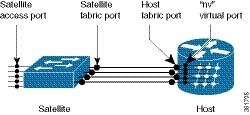
Advanced Satellite nV Topologies
Cisco IOS XR Software supports these advanced Satellite nV System Network Topologies:
- Dual-homed Satellite nV network architecture - In the dual home architecture, two hosts are connected to a satellite through the Satellite Discovery And Control (SDAC) Protocol. The SDAC Protocol provides the behavioral, semantic, and syntactic definition of the relationship between a satellite device and its host. Both these dual-homed hosts act in the active/standby mode for the satellite. The standby host takes control of the satellite only when the active host is down. The two hosts leverage the existing mLACP infrastructure to provide redundant Layer 2 and Layer 3 services for Satellite Ethernet interfaces.
- Simple Ring Satellite nV topology - A satellite or ring of satellites can be dual-homed to two hosts. The two hosts communicate using the ORBIT protocol over ICCP. In simple ring topology, the satellite chassis serial number is a mandatory configuration to identify the satellite. When the ring span is broken. the satellite and hosts detect the link failure using LOS mechanism and perform the necessary switching based Dual Home management.
- Layer 2 Fabric network architecture - In the Layer 2 Fabric network architecture, a satellite is connected to one or two hosts through one of two Ethernet Virtual Circuits (EVC) of Layer 2 Fabric network. An EVC can be identified by two transports VLAN IDs, such as TP-VID-S and TP-VID-H. TP-VID-S is the VLAN ID assigned by the satellite side transport and TP-VID-H is the VLAN ID assigned by the host. The CFM based Fast Fabric Link Failure Detection is supported only in the Layer 2 Fabric Network Architecture.
Refer the Cisco ASR 9000 Series Aggregation Services Router Interface and Hardware Component Configuration Guide for more information on the satellite topologies and configuration.
DHCP RADIUS Proxy
BNG supports DHCP IPv4 RADIUS proxy for RADIUS-based authorization of DHCP leases. This is a RADIUS-based address assignment mechanism in which a DHCP server authorizes remote clients and allocates IP addresses, based on replies from a RADIUS server. For DHCP RADIUS proxy to work, you must configure the DHCPv4 server profile on the BNG interface.
These are the steps involved in the address assignment mechanism:
- The DHCP server sends DHCP client information to the RADIUS server.
- The RADIUS server returns all required information, primarily IPV4 address and subnet mask, to the DHCP server, in the form of RADIUS attributes.
- The DHCP server translates the RADIUS attributes into DHCP options and sends this information back in a DHCP OFFER message to the DHCP client.
- The DHCP binding is synchronized after the RADIUS server authorizes the client session.
If IETF attributes, such as Framed-IP-Address and Framed-IP-Netmask, are received from the RADIUS server, and if they are present in the user profile, then these attributes are used instead of allocating the IP address from the local pool in DAPS.
Apart from these attributes, if the RADIUS server sends the dhcp-class attribute to the DHCP server, then that attribute value is used to decide other configuration parameters in the reply that is to be sent to the DHCP client. For example, if the DHCPv4 server profile has both Class A and Class B in it, and if RADIUS server sends a reply to the DHCP server with the class name as 'B', then instead of Class A, Class B is used to send the options back to the DHCP client.
Additional RADIUS server attributes are allowed, but not mandatory. The DHCP server ignores additional attributes that it does not recognize. If a RADIUS server user profile contains a required attribute that is empty, the DHCP server does not generate the DHCP options.
Line Card Subscribers
BNG supports line card (LC) subscribers which are based on physical access interfaces. This support is in addition to supporting route processor (RP) subscribers, which are based on bundle access-interfaces. Apart from route switch processor (RSP), line cards also support session termination and control plane protocols. For LC subscribers, both control and data planes run on the same node and share the same CPU resource. In contrast, for bundle subscribers, the control plane runs completely on RSP, and the data plane runs completely on LC.
The number of LC subscribers sessions scales linearly with the number of line cards in the system. The maximum number of sessions for each LC is 64000. As more line cards are added to the system, the maximum number of sessions in the system reaches a multiple of 64000 subscribers, the multiplier being the number of line cards.
The calls-per-second (CPS) achieved for each chassis scales almost linearly with the number of line cards in the system. Linearity is not achieved for CPS because of the congestion in the communication channel, arising out of the large number of notifications sent out from LC to RSP.
Routed Subscriber Sessions
BNG supports L3 or routed subscriber sessions, where IP subscribers are connected through a routed access network. The policies and services on the routed subscriber sessions are applied in a similar manner as with L2 subscriber sessions.
Routed subscriber sessions come up only if a summary route is added on BNG. The summary route can be either statically configured, or created through some of the routing protocols like OSPF or EIGRP. The summary route VRF must be same as the access-interface VRF in BNG. Modifying or deleting a summary route that is pointing to the subscriber access-interface, while the subscriber sessions are active, may cause a minimal traffic disruption due to route re-convergence. Therefore, it is recommended that the summary route pointing to the subscriber access-interface be modified or deleted only after deleting the sessions that are using that static summary route.
To configure an access interface to host routed subscriber sessions, see Configuring Routed Subscriber Sessions.
DHCP Interaction
The DHCP pool IP address range in BNG must be in compliance with the summary route address range. This DHCP pool IP address range must also match the IP address subnet of the first hop router, which acts as the DHCP relay or proxy. The route for this particular address range must be configured in BNG, so that BNG can reach the subnet of the first hop router, and eventually reach the subscriber.
The subscriber route need not be explicitly added. It is added internally by the BNG process, when the subscriber session is up.
For routed subscriber sessions, the DHCP server should be configured locally on ASR9K router itself, or a DHCP radius proxy should be used. Proxy mode to an external DHCP server is not supported. For details on the call flow of a DHCPv4-initiated session, see DHCPv4-initiated Routed Subscriber Sessions.
Session Initiator and Session Identifier
Routed sessions should use IP-based session in-band initiator; whereas L2 connected sessions can have unclassified-mac as session in-band initiator. Only DHCPv4 initiated sessions are supported.
Access Interface Features
Although features like ACL and Netflow may be configured on the access-interface, they do not get applied on the subscriber traffic under the respective access-interface. Which features get applied on the subscriber interface is decided based on the dynamic-template configurations under the interface or through RADIUS profile.
VRF Mapping
Routed subscriber sessions support VRF mapping, which allows subscriber to be in a different VRF other than the access-interface VRF. The DHCP pool VRF in BNG must be same as the subscriber VRF, whereas the summary route VRF must be same as the access-interface VRF in BNG. During subscriber creation, information from the dynamic-template or RADIUS is used to set the subscriber VRF. Because access-interface is not used to classify subscriber traffic, the IP address given to subscriber in a given access-interface must be a non-overlapping address.
Non-Subscriber Traffic
Because DHCP is the only session initiator for a routed subscriber, a non-subscriber packet is routed as a normal packet on an access-interface. For such packets, the features on access interface are applicable as normal. To prevent such traffic, you should deploy ACL on the access interface.
Static Sessions
BNG supports interface-based static sessions, where all traffic belonging to a particular VLAN sub-interface is treated as a single session. These sessions are created or deleted, based on the configuration of static session on the sub-interface (access-interface). The session establishment is triggered by creating a static subscriber configuration on a sub-interface; the session termination is triggered by removing that configuration.
The number of static sessions that can be created in a router is the same as the number of Bundle VLAN interfaces that can be present in the router.
Static sessions are present only in the control plane, mainly to provide access to AAA, CoA, and dynamic templates. These sessions have the same flexibility as other kinds of sessions (such as DHCP-triggered sessions and packet-triggered sessions) from the perspective of AAA, CoA, and other dynamic configuration changes.
All forwarding and routing features for static sessions are programmed directly on the access-interface. Features such as Access Control List (ACL), Hierarchical Quality of Service (H-QoS), and Session Accounting are allowed to be configured through RADIUS or through dynamic template.
The IP address for a static session is configured on the access-interface itself. All subnet interface addresses can be assigned to the subscribers in the case of switched Customer Premises Equipment (CPE). The Unicast Reverse Path Forwarding (uRPF) is also configured on the access-interface itself. Because the access-interface is like any other Layer 3 interface, it allows PE-CE routing protocols such as OSPF and BGP.
A static session is similar to a subscriber session, except for these differences:Subscriber Session Limit
The subscriber session limit feature limits the total number of subscriber sessions in a BNG router. If a new subscriber session comes up after the router reaches the overall session limit, then the earliest un-authenticated session is deleted. If the router reaches the overall subscriber session limit and if all the sessions present in the router are authenticated sessions, then the request for a new session is rejected.
Typically sessions belonging to subscribers who do not have the intent of accessing the network services are typically un-authenticated sessions. Per-subscriber features do not apply to such sessions. Instead, they have the same set of features applied to all users. Generally, if the un-authenticated subscriber sessions do not authenticate themselves within a specific time, they are deleted using the un-auth timer mechanism.
The subscriber session limit command is used to apply the overall subscriber session limit in the BNG router.
This figure shows the scenario where a long-lived un-authenticated session is deleted, when a new un-authenticated session (m + 1) comes up after the router reaches the overall session limit. In this example, m+n is the overall session limit, where m is the number of un-authenticated sessions and n is the number of authenticated sessions. The behavior is the same for a new authenticated session (n + 1) too.
Subscriber Session-Restart
BNG supports IPoE subscriber session-restart, where the DHCP binding for a subscriber session is retained even after the session is deleted. The DHCP client still holds the initial IP address issued by BNG. Later, when the client sends data packets or a DHCP renew request, the session is re-created in BNG. This behavior applies to DHCPv4 sessions on RP or LC.
At the time of session deletion, the DHCP binding moves from the BOUND to the DISCONNECT state. The subscriber label is reset to 0x0 when the binding moves to the DISCONNECT state. Later, when the session is re-created, the binding state then moves back from the DISCONNECT to the BOUND. This re-created session has a new subscriber label and a new subscriber interface.
The binding stays in the DISCONNECT state, only till the lease time. If a data packet or renew request does not come before the lease time expires, then the session is cleared.
Session-restart behavior is applicable to session deletions triggered by idle timeout, or by an account-logoff procedure, where the trigger for deletion is any action other than the DHCP release from the client.
Session-restart is not applicable to session deletions done by the execution of the clear subscriber session all command. The DHCP bindings are removed in such cases.
For session deletion triggered by the DHCP client, both the session and the DHCP binding are deleted.
Note
For session-restart to work, you must configure dual initiators (initiator dhcp and initiator unclassified-source) under the access-interface.GRE Tunnel Key
The GRE Tunnel Key feature enables the encapsulation router to add a four-byte key as part of the GRE header during encapsulation. In the decapsulation router, the GRE key of an incoming packet should match the key value configured under the GRE tunnel. During decapsulation, if a mismatch between the key value of the incoming GRE packet and the key value configured under the GRE tunnel is identified, the incoming packet is dropped.
For more information on the GRE tunnel key feature, see the Cisco ASR 9000 Series Aggregation Services Router MPLS Layer 3 VPN Configuration Guide, Release 5.1.x . For information on the commands used for GRE tunnel configuration, see the Cisco ASR 9000 Series Aggregation Services Router L2VPN and Ethernet Services Command Reference, Release 5.1.x .
MMRP for PBB VPLS Flood Optimization
In a PBB network, traffic (unknown unicast, multicast, or broadcast) is flooded to all the PE devices in the network even if the devices do not host the service instance to which the traffic is destined.
The MMRP for PBB VPLS Flood Optimization feature optimizes the impact of the flooded traffic on PE devices by sending the traffic only to the PE devices interested in a particular service instance.
For more information on MMRP for PBB VPLS flood optimization feature, see the Cisco ASR 9000 Series Aggregation Services Router L2VPN and Ethernet Services Configuration Guide. For information on the commands used for configuring MMRP for PBB VPLS flood optimization, see the Cisco ASR 9000 Series Aggregation Services Router L2VPN and Ethernet Services Command Reference, Release 5.1.x .
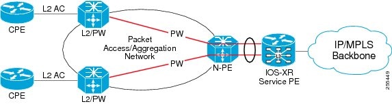
Dynamic Single Segment Pseudowire
A single segment pseudowire (SS-PW) is a point-to-point pseudowire (PW) where the PW segment is present between two PE routers.
For more information on SS-PW feature, see the Cisco ASR 9000 Series Aggregation Services Router L2VPN and Ethernet Services Configuration Guide.
LFA over PW-HE
PW-HE is supported on loop free alternate (LFA) routes. For LFA to be effective on a PW-HE interface, all the routing paths (protected and backup) must be included in the generic interface list of that PW-HE interface.
For more information on LFA over PW-HE, see the Cisco ASR 9000 Series Aggregation Services Router MPLS Configuration Guide, Release 5.1.x.
PW-HE Ethernet Sub-interfaces and Interworking Interfaces (VC-type 11)
The PW-HE is created by configuring pw-ether main interface, pw-ether subinterface, or pw-iw interface. The available PW-HE types are pw-ether main interfaces, subinterfaces, and pw-iw interfaces.
Cross-connects that contain PW-Ether main interfaces can be configured as either VC-type 5 or VC-type 4.
Cross-connects that contain PW-Ether main interfaces, which have L3 PW-Ether subinterfaces associated with them, are supported with only VC-type 5.
Cross-connects that contain PW-IW interfaces are only supported with IPv4 and VC-type 11. PW-IW interfaces are the L3 virtual interfaces used for IP interworking.
For more information, see the Cisco ASR 9000 Series Aggregation Services Router L2VPN and Ethernet Services Configuration Guide.
Auto-IP
In ring topology, when a device is inserted into the ring, the neighboring node interfaces require manual reconfiguration. The auto-IP feature addresses the problem of manually reconfiguring nodes during insertion, deletion, and movement of nodes within the ring. The auto-IP feature automatically provides IP addresses to the nodes inserted into the ring.
The Auto-IP feature is an enhancement of Link Layer Discovery Protocol (LLDP). LLDP supports a set of attributes that it uses to discover neighbor devices. These attributes contain type, length, and value descriptions, and are referred to as a Type Length Value (TLV).
In a ring topology, two network-to-network interfaces (NNIs or node interfaces) of a device are used to be part of a ring. The auto-IP feature is an automatic method to provide IP addresses to the node interfaces inserted into a ring. One node interface is designated as the 'owner' interface and the other as the 'non-owner' interface.
For a ring to function as an auto-IP ring, you must enable the auto-IP functionality on all the node interfaces within a ring.
Auto-IP is supported only on Ethernet interfaces, port-channel interfaces, port-channel sub-interfaces, bundle interfaces, and bundle-sub interfaces.
Note
The two node interfaces which are designated to be part of a ring must be configured with the same auto-IP address.
Auto-IP address is used for allocation purposes only and not used as an IP address for a node interface until the IP address is configured on an interface.
The Auto-IP feature is not supported on IPv6 addresses.
Prerequisites for Auto-IP
Link Layer Discovery Protocol (LLDP) must be enabled on the device before enabling the auto-IP functionality on a node interface.
Restrictions for Auto-IP
- Auto-IP addresses should contain an odd number in the last octet (such as 10.1.1.1, where the number in the last octet is 1).
- The auto-IP feature is not supported on a virtual routing and forwarding (VRF). Auto-IP address configuration must not be configured on an interface which belongs to a VRF other than the global or default VRF.
- IP address configuration should not be performed manually on owner and non-owner interface after auto-IP configuration is performed.
- A maximum of two interfaces are allowed with in a ring in a router.
- Ring interface should not be configured with two different auto-IP addresses with same ring-ID in a router.
- Same auto-IP address should not be configured in two routers.
DHCPv4 Local Server enhancements
DHCPv4 Client-Relay-Server Topology
ASR9K supports DHCPv4 Client-Relay-Server topology. The main features are:
- VRF awareness (RFC and CISCO modes, except TYPE-1, are supported):
- For standalone mode, if a VPN-ID sub-option is inserted by the relay, then the same VRF is used to select a pool under the matching class. If VPN-ID sub-option is not inserted by the relay, then the relay-interfacing or the client-interfacing VRF is used to select a pool under the matching class. The dynamic address pool server (DAPS) allocates the IP address from the same pool and VRF.
- For BNG mode, the VPN-ID sub-option is ignored. The VRF is read from the subscriber database only. The same VRF is used for pool selection also.
- IP address allocation based on the received DHCP Options 60, 77, 124 and 125:
- The data values of received DHCP options 60, 77, 124 and 125 are compared with the configured values of these options within a class. The order of matching a class is VRF, CID, RID, Option-60, Option-77, Option-124 and Option-125. All the values must match. The pool from the same address class is used to allocate the IP address.
- IP address allocation based on the received relay information, Circuit-ID (CID) and Remote-ID (RID):
- Support for Server-Id-Override sub-option (RFC and CISCO modes are supported):
- Support for Option-50 (Requested-IP):
- Support for Subnet-Selection sub-option (RFC and CISCO modes are supported):
- If the client is directly connected to the server, then the client-facing interface IP address is used as the subnet.
- If Option-50 is not inserted by the client, but if the Subnet-Selection sub-option is inserted by the relay, then the DAPS allocates the requested IP address within the received subnet. If the DAPS cannot allocate the IP address in the given subnet, then the packet is dropped.
- If Option-50 was not inserted by the client, and if Subnet-Selection sub-option was also not inserted by the relay, then the gateway IP address is considered as the subnet. The DAPS allocates the requested IP address within the same subnet.
A new command, option dhcp-option-code, is introduced to provide a generic interface to insert server specific options in raw format (ASCII, HEX and IP). The DHCP options 0, 1, 3, 6, 12, 15, 44, 46, 50, 51, 52, 53, 54, 58, 59, 61, 82 and 255 are not supported for this command.
Carrier-Supporting-Carrier Support for MPLS LDP
The carrier-supporting-carrier (CSC) support for MPLS LDP feature enables MPLS label distribution protocol (LDP) to provide carrier-supporting-carrier (CSC) support for Layer 3 Virtual Private Networks. To support LDP as label distribution protocol between PE-CE devices in an MPLS CSC L3VPN, LDP is required to operate in multiple VRF contexts. To support multiple VRFs, the LDP configuration model is be extended to allow VRF sub-mode and per-VRF configuration.
MPLS TE Extended Admin Groups
The MPLS TE extended admin groups (EAG) configuration assigns EAG/AG name to bit-position and associates affinity-names with TE links. The configuration extends to assign names, up to 256, to TE links over the selected interface and assigns 32 names per attribute-set and index.
Use the affinity-map map-name bit-position value command to assign EAG/AG name to bit-position. Use the attribute-names attribute-name1 attribute-name2 ... and attribute-names index index-number attribute-name1 attribute-name2 ... commands to assign up to 32 names per attribute-set and index value.
MPLS TE IPv6 Autoroute
The MPLS TE IPv6 Autoroute feature enables the use of IPv4 MPLS TE tunnels for IPv6 routing. The routing protocol IGP (IS-IS) considers the IPv4 MPLS TE tunnel for IPv6 routing path calculation only if the tunnel is advertised to carry IPv6 traffic. To advertise the tunnel, either IPv6 autoroute announce (AA) configuration or IPv6 forwarding adjacency (FA) configuration should be made on the tunnel. Also, the IPv6 has to be enabled on the tunnel so that the tunnel can handle IPv6 traffic.
To configure IPv6 routing on an MPLS TEv4 tunnel, see Configuring IPv6 Routing Over IPv4 MPLS-TE Tunnels.
MPLS TE Usability Enhancements
MPLS traffic engineering command line interface and logging output messages are enhanced as follows:
- The show mpls traffic engineering commands display signaled-name and supports signaled-name filter.
- Ability to allow immediate teardown of all labelled switched paths ( LSPs) of the specified tunnel and to create new LSPs.
- Default behavior when affinity check fails at head-end is to reoptimize all LSP types.
- Logging output messages include MPLS TE tunnel signaled name.
- Logging of path change events and available bandwidth on the new for all auto-bandwidth operations.
- Auto-bandwidth logging output includes signaled name.
Policy Based Forwarding
Policy Based Forwarding (PBF) addresses the ability to forward packets based on these match conditions: Src address, Dst address, Protocol (TCP/UDP) and port number, DSCP markings, and Tos values. PBF works for both IPv4 and IPv6 address families.
PBF is supported only on ASR 9000 Enhanced Ethernet Line Cards.
PBF enables packet forwarding to the specified IPv4 /IPv6 next-hop based on packet classification using class-map.
NotePolicy based Forwarding (PBF) and Flow aware policy (UBRL/CAC) features will not work together on the same interface/direction.
PWHE over MPLS TE Tunnels
The PWHE over MPLS TE Tunnels feature supports forwarding of Pseudowire traffic (with Pseudowire Headend) over MPLS traffic engineering (TE) tunnels. PWHE over MPLS TE Tunnels supports PW-Ether and PW-IW with pseudowire forwarding over TE tunnels.
- TE tunnel cannot be configured as preferred-path for the PWHE-based Pseudowire. The preferred-path tunnel-te option under L2VPN XConnect PW-Class is not supported.
- Routing must be configured so that the route to the Pseudowire peer endpoint uses the TE tunnels.
- The TE tunnels can be configured with either "explicit" or with "dynamic path".
- TE tunnels redundancy and TE fast-reroute are supported with PWHE over MPLS TE tunnels.
No special configuration is required for TE tunnels to provide forwarding for PWHE-based Pseudowire. The default TE tunnel configuration is used for enabling PWHE over MPLS TE tunnels.
For information on MPLS TE configuration, refer Implementing MPLS Traffic Engineering module in Cisco ASR 9000 Series Aggregation Services Router MPLS Configuration Guide.
For more information on PWHE configuration, refer Cisco ASR 9000 Series Aggregation Services Router L2VPN and Ethernet Services Configuration Guide. For more information on the commands used for PWHE configuration, refer Cisco ASR 9000 Series Aggregation Services Router L2VPN and Ethernet Services Command Reference.
Stateful Path Computation Element
The stateful path computation element (PCE) describes a set of procedures by which a path computation client ( PCC) can report and delegate control of head-end tunnels sourced from the PCC to a PCE peer. The PCE peer can request the PCC to update and modify parameters of label switched paths (LSPs) it controls. The stateful model also enables a PCC to allow the PCE to initiate computations allowing the PCE to perform network-wide orchestration.
The transfer of LSP state and computation constraints is independent from the computation request, such that a PCE may see how state changes over time, without a computation request ever taking place. This allows the PCE to have better visibility into network state, as well as improve the efficiency of computation requests, as these can rely on state present on the PCE.Stateful PCE provides support for these following request types and objects:VRF Redirection to MPLS TE Tunnels
The VRF redirection to MPLS TE tunnels feature adds automatic route MPLS TE tunnels through autoroute destination configuration. The VRF redirection to MPLS TE tunnels maps VRF prefixes over TE tunnels in the core to reach the same egress provider edge (PE). This enables to load-balance prefix traffic on multiple tunnels based on equal cost multi-path (ECMP). The ECMP is used to load-share the flow(s) on multiple available paths towards the destination PE. The route added by autoroute destination inherits the same IGP computed metric to the tunnel endpoint. Any changes to the IGP route metric to the tunnel endpoint is automatically reflected on the autoroute destination route too.
In a typical VPN deployment over a TE core network, an operator creates a mesh of TE tunnels between PE routers and then configures autoroute announce to these tunnels. This leads to a mix of default VRF and VPNv4 traffic on the same tunnel connecting the PE routers. An operator my want to segregate their VPNv4 traffic on different tunnels. This can be achieved by creating multiple tunnels to the egress PE(s). The limitation of this approach is that the static routes are added with zero metrics. The VRF Redirection to MPLS TE Tunnels feature is a solution to resolve this limitation. Multiple VRFs can be mapped on the same tunnel by adding multiple autoroute destination addresses (BGP next-hops) to the same tunnel.
Routes added by static route are always added with zero cost metric. This results in traffic that is mapped on multiple tunnels to always load-balance due to ECMP. This may be undesirable when some of those tunnels have sub-optimal paths (have higher underlying cost to the endpoint). With autoroute destination, only the tunnel whose IGP cost to its endpoint is lowest will be considered for carrying traffic.
VRF redirection over TE tunnels feature supports:
- Automatic redirection of VRF traffic over TE tunnels.
- Multiple autoroute destinations under one tunnel to aggregate VRF traffic. If two VRFs are to be mapped on same tunnel, then two autoroute destination prefixes (BGP next-hops) will be configured under the tunnel.
- One autoroute destination under multiple tunnels to enable ECMP load-balance of VRF traffic.
- Implicit /32 mask for each route. Only host addresses residing on the tunnel endpoint are supported.
- High availability, RP failover, and non-stop forwarding (NSF) scenarios by proving hitless to traffic mechanisms.
Flow Aware QoS
In Cisco ASR 9000 Series Routers, the granular control of traffic flow is achieved by applying static match criteria and associated QoS action on traffic flow. With real-time on-demand VoIP and video traffic applications, and tailor-made user services, there is an increasing need for the QoS actions to be more flow, application and session aware as opposed to being static, configuration based and stateless. Flow aware QoS feature provides this functionality to QoS and creates a framework to define flow aware QoS solutions such as call admission control or per-user traffic rate limiting.
The Flow aware QoS feature enables QoS actions to be applied at a flow level. The flows are detected or learnt dynamically on a per-class, per-interface, per-direction level and the QoS action or decisions are applied on a per-flow basis guided by a QoS policy applied on the interface. The framework also provides an option to enforce admission control on the incoming traffic to preemptively prevent congestion.
The Flow aware QoS feature suite provides:
- User-defined flow definition—You can define a flow from a flexible choice of flow tuples (srcip, dstip, L4 protocol, sport, dport)
- Configurable flow bandwidth to decide how many video flows to allow—You can configure the flow bandwidth to decide how many video calls/flows to allow pass through a system without causing congestion.
- Redirection of non-admitted flows to default queue—You can redirect all the best-effort delivery traffic flows that exceed a predetermined admissible bandwidth to a default queue thereby providing guaranteed service on a per-flow basis.
- Configurable flow entry idle-timeout to tune as per use case or traffic profile— There are configurable flow age timeouts based on the traffic profile. You can set a timeout and ensure service fairness.
Inter-Class Policer Bucket Sharing
Based on different classification criteria, inter-class policer bucket sharing feature allows policer bucket sharing among different classes in a hierarchical QoS model, within the modular quality of service command line (MQC) construct, to achieve multirate policing of the same packet. In this feature, the classification of the incoming packet happens only once. However, the policer bucket is shared among classes; that is the same token bucket is used even though a match happens against different classes.
This feature includes following components:
QoS Offload on Satellite
The Cisco ASR 9000 Series Router Satellite System enables you to configure a topology in which one or more satellite switches complement one or more Cisco ASR 9000 Series routers, to collectively deploy a single virtual switching system. In this system, the satellite switches act under the management control of the routers. The connections between the Cisco ASR 9000 Series Router and the satellite switches are called the Inter-chassis link (ICL), which is established using standard Ethernet interfaces.
The ICL link between the Cisco ASR 9000 Series Router and the satellite gets oversubscribed by the access interfaces on the satellite box. This is because the QoS policies applied on the satellite interfaces are programmed on the Cisco ASR 9000 Series Router Line card locally. Therefore, the flow of traffic on the ICL from the satellite switch is not controlled. This leads a loss of high-priority traffic due to congestion on the ICL.
This figure shows the ports where the QoS policies may be applied.
QoS on Pseudowire Headend
A pseudowire (PW) headend (PWHE) virtual interface originates as a PW on an access node (the Layer 2 PW feeder node) and terminates on a Layer 3 service instance, such as a VRF instance, on the service provider router. All ingress and egress QoS functions can be configured on the interface, including policing, shaping, queuing, and hierarchical policies.
This figure illustrates PWs originating on access node (L2/PW feeder node) and terminating on the service provider edge (Service PE). The composite Layer 2 attachment circuit (AC) plus PW segment forms a point-to-point virtual link that functions and behaves the same as traditional Layer 3 links. Although the PWHE interface is virtual, the traffic corresponding to that interface is sent and received over a single physical interface.
The QoS policy on PWHE virtual interface can coexist with the QoS policy on its underlying physical interfaces. These two figures (one each for the ingress and egress directions) show the application of QoS for physical and PWHE traffic.
The PWHE virtual interface is provisioned as a regular Layer 3 interface, and all QoS features that are supported on regular Layer 3 interfaces are supported on PWHE virtual interfaces. All ingress and egress QoS functions can be configured on the interface, including policing, shaping, queuing, and hierarchical policies. These details apply to header fields for traffic on PWHE interfaces:
- QoS classification and marking functions are based on the inner packet IP header and Layer 2 header fields. Marking of EXP bits for all imposed labels is supported in both ingress and egress QoS policies.
- If you configure Layer 2 overhead on the PWHE interface, the system adds this Layer 2 overhead to the packet length and then performs QoS functions.
The common MQC restrictions for QoS policies on Layer 3 interfaces apply to QoS policies for PWHE interfaces. In addition, these restrictions apply to QoS policies on PWHE interfaces:
- Configure the policy as a hierarchical policy with a single default class in the parent policy. Nonhierarchical policies are not supported.
- Configure either a police or shape command in the parent default class with an absolute rate. Percentage units are not allowed for police and shape commands in the parent default class.
- If you configure a police command without a shape command, you must configure a drop action within either the exceed action or the violate action.
Multicast IRB
Multicast IRB provides the ability to route multicast packets between a bridge group and a routed interface using a bridge-group virtual interface (BVI). It can be enabled with multicast-routing. THE BVI is a virtual interface within the router that acts like a normal routed interface. For details about BVI, refer Cisco ASR 9000 Series Aggregation Services Router Interface and Hardware Component Configuration Guide
BV interfaces are added to the existing VRF routes and integrated with the replication slot mask. After this integration, the traffic coming from a VRF BVI is forwarded to the VPN.
LSP-switch for P2MP-TE
Turnaround for P2MP-TE can be handled by LSP-switch with a partitioned profile. For partitioned profiles, there is no core tree (where all the PEs join). When the traffic arrives at the ingress PE, it is forwarded to the RP-PE on a LSP. The RP-PE must then switch the traffic to a different LSP for all the non-RP PE receivers.
Multicast support for PW-HE interfaces
Multicast support for Pseudowire Head-end (PW-HE) interfaces is available only on the enhanced ethernet cards.
Multicast support is available under these circumstances:
- IPv4 and IPv6 multicast traffic forwarding over the L3 PW-HE interface/sub-interface. PW-HE interface type can be PW-ether (VC4 or VC5) or PW-iw (VC11). IPv6 multicast is not available on VC11.
- L3 PW-HE interfaces/sub-interfaces in global , MVPNv4 and MVPNv6 VRFs.
- L3 PW-HE interface/sub-interfaces in MVPNv4 and MVPNv6 where the core can be GRE or MLDP.
- PIM-SM, PIM-SSM (PE-CE) , MSDP and PIM Auto-RP over the PW-HE interface.
- IGMP/ MLD snooping on L2 PW-HE VC5 sub-interface.
- VC label-based load balancing.
Two-Way Active Measurement Protocol (TWAMP)
The Two-Way Active Measurement Protocol (TWAMP) defines a flexible method for measuring round-trip IP performance between any two devices.
Software Feature Enhancements
These software feature enhancements are introduced in Cisco IOS XR Software Release 5.1.1.
- The BGP/RIB scale is increased to 2.5 GB.
- The minimum ROMMON version required for ASR9001 in Cisco IOS XR Software Release R5.1.1 is 2.03.
- Support for multi-chassis link aggregation on IPv6 traffic was included.
- Support for 40 GE and 100 GE interfaces as Inter-Rack Links (IRL) on Cisco ASR 9000 Series nV Edge System was included.
- Support for MGSCP (Multi-Gigabit Service Control Point) on IPv6 was included.
Hardware Features Introduced in Cisco IOS XR Software Release 5.1.1 for the Cisco ASR 9000 Series Router
Cisco IOS XR Software Release 5.1.1 introduces support for the following:
- Optional air plenum kit for the Cisco ASR 9000v Satellite Shelf, Cisco ASR901 Router (ASR 9000V-901-DEF=), and the Cisco ASR 9001 Router (ASR-9001-BAFFLE=), used for mounting the router in a 2-post or 4-post adjustable 23-inch rack or a 2-post flat 19-inch rack.
- Cisco ASR 9000v satellite shelf (ASR-9000v-24-A) with 24V DC power module for ANSI standard +24 Volt PID creation.
- A901-6CZ-F-D—Cisco ASR 901 Series Aggregation Services Router Chassis, Ethernet-only interfaces, 10 GE, DC power, USB.
- A901-6CZ-FT-D—Cisco ASR 901 Series Aggregation Services Router Chassis, Ethernet and TDM interfaces, 10 GE, DC power, USB.
- A901-6CZ-F-A Cisco ASR 901 Series Aggregation Services Router Chassis, Ethernet-only interfaces, 10 GE, AC power, USB.
- A901-6CZ-FT-A— Cisco ASR 901 Series Aggregation Services Router Chassis, Ethernet and TDM interfaces, 10 GE, AC power, USB.
Note
The Cisco ASR 901 router does not support 10 GE interfaces as ICL or access ports.- MR-APS support on SPA-1XCHOC48/DS3—Multirouter Automatic Protection Switching (MR-APS) provides redundancy to the ASR 9000 platform at the Layer 1 level. This is achieved by the termination of the APS working and protect interfaces on two separate routers. The two routers are interconnected by an OOB (Out of Band) channel, over which the APS state is communicated to the standby router. PGP (Protect Group Protocol), a Cisco proprietary protocol runs on this channel. Any interface can be used for the OBB channel but we recommended that you use a reliable dedicated channel (with no user data traffic) between the working and protect routers.
- Support for the lead-free (Pb-free) version of SPA-8XCHT1/E1-V2 module with new CPU, flash, and FPGA.
- Support for the lead-free (Pb-free) version of the SPA-1XOC48POS/RPR module. OC48 SPA is a one port, single width half height plug-in module.
- Support for the following optic modules:
- ONS-SC+-10G-C (limited to a maximum of 12 modules per line card)
- GLC-FE-100EX/GLC-FE-100ZX (supported on ASR 9000 Enhanced Ethernet Line Card and Cisco ASR 9001 router)
- CFP-100G-ER4
- ONS-XC-10G-1470 through ONS-XC-10G-1610
- ONS-SC+-10G-SR
- ONS-SC+-10G-ER
- ONS-SC+-10G-LR
- ONS-SC+-10G-ZR
- ONS-SE+-10G-LR
- ONS-SC+-10G-xx.y
- SFP-10G-ZR (supported on fixed ports of Cisco ASR 9001 router)
- DWDM-SFP10G-XXXX (supported on fixed ports of Cisco ASR 9001 router)
- ONS-SC+-10G-C (supported on fixed ports of Cisco ASR 9001 router)
Cisco ASR 9000 Series Optics Support
These restrictions applies to the Cisco ASR 9922 Router and Cisco ASR 9912 Router with V1 Fan Tray.
- Due to increased power draw and thermal requirements, usage of high power optics and tunable optics are restricted. Cisco does not bear any responsibility in case of damage if these optics are used with an ambient temperature above 45 degrees Celsius in any chassis/card combination.
- Port restrictions for 24x10GE Line Card: If the ambient temperature is between 40 and 45 degrees Celsius, the ports 12 -23 can be used for builds before February 2013 and ports 0-1, 4-6, 11-13, 16-18 and 23 can be used for tunable DWDM optics and the rest for fixed DWDM for builds after February 2013.
- Port restrictions for 34x10GE Line Card: If the ambient temperature is between 40 and 45 degrees Celsius, the ports 12 -23 can be used for builds before February 2013 and ports 0, 5-6, 11-13, 16-17, 26, 28, 30, and 35 can be used for tunable DWDM optics and the rest for fixed DWDM for builds after February 2013.
- Cisco IOS XR Software Release 5.1.1 does not restrict the use of tunable optics or high power optics with the Enhanced Ethernet Services Line Card models A9K-36x10G-TR/SE, A9K-24x10G-TR/SE, or 8x10G Modular Port Adapter (MPA) in either the Cisco ASR 9010 or Cisco ASR 9922 chassis. To run these optics on the Cisco ASR 9010 chassis, use of the Cisco ASR 9000 Router V2 fan tray is recommended.
- The ambient temperature must remain below 40 degrees Celsius. The ambient temperature is measured by the inlet sensor on the RSP. To display the temperature, use the admin show environment temperature command.
Important Notes
Starting Cisco IOS XR Software Release 4.3.2, the Flow Aware Transport (FAT) Pseudo Wire default label value changed from 0x11 to 0x17 (as per directions of the IANA). When building FAT pseudo wires between XR releases post 4.3.2 and 4.3.1 and prior, a configuration is necessary to set the flow label value to the old value of 0x11 (which is 17 decimal in the configuration. Please refer to the configuration guide for FAT Pseudowire for the exact command sequence or find more information on the ASR9000 BLOG on the support forums.
For Cisco IOS XR Software Release 4.2, the Cisco ASR 9000 Series Aggregation Services Router does not support the following inventory schemas:- vkg_invmgr_adminoper.xsd- vkg_invmgr_common.xsd- vkg_invmgr_oper.xsd
- Only MLPPP encapsulation channels on the OC-12 SONET interface can be protected by IP-FRR in Cisco IOS XR software Release 3.9.0 and above.
- For Cisco IOS XR software Release 3.9.0 and above the SIP 700 with the 2-Port Channelized OC-12/DS0 SPA does not support SDH (including all the mappings under SDH) or DS0 mappings.
- For Cisco IOS XR software Release 3.9.0 and above the SIP 700 with the 2-Port Channelized OC-12/DS0 SPA does not support ATM or POS.
- For Cisco IOS XR software Release 3.9.0 and above the SIP 700 with the 2-Port Channelized OC-12/DS0 SPA does not support MPLS/Traffic Engineering FRR.
- For Cisco IOS XR software Release 4.0.1 and above the SIP 700 with the 1-Port Channelized OC48/STM16 DS3 SPA does not support MPLS/Traffic Engineering FRR.
- For Cisco IOS XR software Release 4.0.1 and above the SIP 700 with the 1-Port Channelized OC48/STM16 DS3 SPA, the 2-Port Channelized OC-12/DS0 SPA , the 8-Port OC12/STM4 SPA , and the 2-Port OC-48/STM16 SPA Layer 2VPN support only includes FR.
- Country-specific laws, regulations, and licenses—In certain countries, use of these products may be prohibited and subject to laws, regulations, or licenses, including requirements applicable to the use of the products under telecommunications and other laws and regulations; customers must comply with all such applicable laws in the countries in which they intend to use the products.
- Card fan controller, and RSP removal—For all card removal and replacement (including fabric cards, line cards, fan controller, and RSP) follow the instructions provided by Cisco to avoid impact to traffic. See the Cisco ASR 9000 Series Aggregation Services Router Getting Started Guide for procedures.
- Exceeding Cisco testing—If you intend to test beyond the combined maximum configuration tested and published by Cisco, contact your Cisco Technical Support representative to discuss how to engineer a large-scale configuration maximum for your purpose.
- Installing a Line Card—For a fully populated 40-port high density Line Card with cable optics, maintenance time required for card replacement is higher. For more information about Line Card installation and removal, refer to the Cisco ASR 9000 Aggregation Services Router Ethernet Line Card Installation Guide.
- Serial Interfaces Out of Order in "show ip interface brief" Command—The show ip interface brief command might display interfaces out of order if different types of serialization are used on the SPA cards. The serial interfaces are displayed in the show ip interface brief command output in the order shown in the example below: The ordering is based on: This may be confusing (the interfaces appear out of order) for the user who is accustomed to IOS. Example output: With multiple cards:
Serial0/2/0/1/1/1:0 (t3/t1) Serial0/2/0/1/2/1:0 Serial0/2/0/1/3/1:0 Serial0/2/0/1/4/1:0 Serial0/2/0/1/5/1:0 Serial0/2/0/1/6/1:0 Serial0/2/0/1/7/1:0 Serial0/2/0/1/8/1:0 Serial0/2/0/1/9/1:0 Serial0/2/0/1/10/1:0 Serial0/2/0/1/11/1:0 Serial0/2/0/1/12/1:0 Serial0/2/0/0/1/1/1:0 (vt15) Serial0/2/0/0/2/1/1:0 Serial0/2/0/0/3/1/1:0 Serial0/2/0/0/4/1/1:0 Serial0/2/0/0/5/1/1:0 Serial0/2/0/0/6/1/1:0 Serial0/2/0/0/7/1/1:0 Serial0/2/0/0/8/1/1:0 Serial0/2/0/0/9/1/1:0 Serial0/2/0/0/10/1/1:0 Serial0/2/0/0/11/1/1:0 Serial0/2/0/0/12/1/1:0 Multilink 0/2/0/0/1 Serial0/2/1/0/1 (t3) Serial0/2/1/1/1/1:0 (t3/t1) Serial0/2/1/1/2/1:0 Serial0/2/1/1/3/1:0 Serial0/2/1/1/4/1:0 Serial0/2/1/1/5/1:0 Serial0/2/1/1/6/1:0 Serial0/2/1/1/7/1:0 Serial0/2/1/1/8/1:0 Serial0/2/1/1/9/1:0 Serial0/2/1/1/10/1:0 Serial0/2/1/1/11/1:0 Serial0/2/1/1/12/1:0 Serial0/6/0/1/1/1:0 Serial0/6/0/1/2/1:0 Serial0/6/0/1/3/1:0 Serial0/6/0/1/4/1:0 Serial0/6/0/1/5/1:0 Serial0/6/0/1/6/1:0 Serial0/6/0/1/7/1:0 Serial0/6/0/1/8/1:0 Serial0/6/0/1/9/1:0 Serial0/6/0/1/10/1:0 Serial0/6/0/1/11/1:0 Serial0/6/0/1/12/1:0 Serial0/6/0/0/1/1/1:0 Serial0/6/0/0/2/1/1:0 Serial0/6/0/0/3/1/1:0 Serial0/6/0/0/4/1/1:0 Serial0/6/0/0/5/1/1:0 Serial0/6/0/0/6/1/1:0 Serial0/6/0/0/7/1/1:0 Serial0/6/0/0/8/1/1:0 Serial0/6/0/0/9/1/1:0 Serial0/6/0/0/10/1/1:0 Serial0/6/0/0/11/1/1:0 Serial0/6/0/0/12/1/1:0 Multilink 0/6/0/0/1 Serial0/6/1/0/1 Serial0/6/1/1/1/1:0 Serial0/6/1/1/2/1:0 Serial0/6/1/1/3/1:0 Serial0/6/1/1/4/1:0 Serial0/6/1/1/5/1:0 Serial0/6/1/1/6/1:0 Serial0/6/1/1/7/1:0 Serial0/6/1/1/8/1:0 Serial0/6/1/1/9/1:0 Serial0/6/1/1/10/1:0 Serial0/6/1/1/11/1:0 Serial0/6/1/1/12/1:0- Starting with Cisco IOS XR Software Release 3.9 the pw-class class name encapsulation mpls command control-word option default is now disable -In Cisco IOS XR Software Release 3.9 and above the control word is disabled by default. To configure the control word, enter the control-word keyword shown in the following example:
pw-class class1 encapsulation mpls control-word- For configured policer rates of less than 1 Mbps, the actual policer rate can be approximately 10 percent less than the configured rate. For example, for a configured policer rate of 500 kbps, the actual policer rate is 448 kbps due to a granularity round down in hardware.
- In Cisco ASR 9000 Series Aggregation Services Router Software Release 4.0.0, the minimum configurable logging buffered size has been increased to 307200. Any configuration with a value less than 307200 fails to upgrade to Release 4.0.1.
- dsu mode Command Default— For E3 interfaces on the 4-Port Clear Channel T3/E3 SPA that interoperate with E3 interfaces on a Cisco 10000 Series router, the default data service unit (DSU) mode is digital-link. To change the DSU mode to cisco, configure scrambling.
- Starting from Cisco IOS XR Software Release 4.0.0, the hw-module location <LOC> reload warm command is disabled. As a result, the warm reload feature also has been disabled.
- In Cisco ASR 9000 Series Aggregation Services Router Software Release 4.1.0, you use the cablelength short command to set a cable length of 655 feet or shorter for a DS1 link on a 4-Port Channelized T1/E1 SPA. The cablelength short command options are listed as follows:
However, when using the cablelength short command on a 4-Port Channelized T1/E1 SPA in Cisco ASR 9000 Series Aggregation Services Router Software Release 4.1.0, only the 133ft option (for cable lengths from 0 to 133 feet) works. The other values that are greater than 133 feet (266, 399, 533, or 655) all cause the T1 controller to go down. The workaround is to restart the controller after you set the cable length to 266, 399, 533, or 655 feet. The cablelength long command works correctlyRP/0/RSP0/CPU0:vkg_ro1_a(config-t1)#cablelength short ? 133ft 0-133ft 266ft 134-266ft 399ft 267-399ft 533ft 400-533ft 655ft 534-655ft
Caveats
Caveats describe unexpected behavior in Cisco IOS XR Software releases. Severity-1 caveats are the most serious caveats; severity-2 caveats are less serious.
This section lists the caveats for Cisco ASR 9000 Series Aggregation Services Router Software Release and the Cisco ASR 9000 Series Aggregation Services Router platform.
- Cisco IOS XR Caveats
- Caveats Specific to the Cisco ASR 9000 Series Aggregation Services Router
- Caveats Specific to the ASR 9001 Router
Cisco IOS XR Caveats
The following open caveats apply to Cisco IOS XR Software Release 5.1.11 and are not platform specific:
- CSCul27315 Basic Description: BGP Process crash with %ROUTING-BGP-3-NOMSGCHUNK messages. Symptom Continuous rise in BGP memory usage followed by a crash with syslog %ROUTING-BGP-3-NOMSGCHUNK. Conditions: There is a churn in the BGP AD VPWS paths, paths are added and deleted continuously for the same Xconnect mp2mp. This causes the VPWS sub-tlvs to proliferate. Workaround: Check for loop in the network or why the peer is continuously adding/deleting the VWPS routes.
- CSCun31535 Basic Description: cvplsGenericMIB issues with BGP-AD. Symptom When querying cvplsConfigVpnId, the returned length is either 0 or 4 (not 7), which means the OUI is not fully shown. Conditions: This issue can be seen when BGP-AD is configured under a bridge-domain. Workaround: None.
- CSCum91881 Basic Description: BGP crashes in CDM library at active RSP after router reload. Symptom BGP crashes at active RSP node. Conditions: This occurs after router reload using the reload loc all command. Workaround: None. BGP process recovers itself after the crash.
- CSCuh97547 Basic Description: BGP process crash @ bgp_fwdentry_info on heavy route flaps. Symptom BGP process crash observed when router undergoes route churn. Route churn as a result of triggers like clear bgp command may also hit this issue. Conditions: Router running Cisco IOS XR Software Release 5.1.1 software with label RPF feature configured AND BGP undergoes heavy route churn with prefix scale of around 420K v4 and 60k v6 routes. Workaround: None.
- CSCuj77052 Basic Description: IPv6 sessions with ND framed prefix delegation go down post RPFO. Symptom Immediately after an RPFO, IPv6 PPPoE sessions are brought down by the router and IPv6 traffic stops flowing on the sessions. This is accompanied by the following error message on the console (where addresses displayed will depend on the router's configuration): %ROUTING-RIB-3-ECMP_ERR_ADD : Path add exceed max number of paths supported by protocol. Table 0xXXXXXXXX, prefix XXXX:X:X::/64, protocol subscriber, intf 0xXXXXXXXX, tunnelid 0, nexthop_table 0xXXXXXXXX, nexthop fe80::XXX:XXXX:XXXX:XXX Conditions: This issue occurs with IPv6-only or dual stack PPPoE subscriber sessions when the ipv6_rib process is restarted or following an RP failover. This is observed when "ipv6 nd framed-prefix-pool" is used to delegate the prefix. Workaround: None.
- CSCul82815 Basic Description: VTY_disconnect is not able to clear allocated TTY. Symptom VTY line not getting cleared up on child channel exit. New child channel allocates a next available VTY line and very soon all VTY lines would be exhausted. Conditions: Using SSH client which support multichannel (openssh 5.0 or higher version). Workaround:
- CSCum59810 Basic Description: qos_ma crash if input Satellite QoS offload configured under ICL. Symptom qos_ma process crash observed during router boot-up. This happens with an incorrect service-policy configuration on an ICL interface (interface connected to Satellite). Conditions: The following mis-configuration can cause this crash:
interface TenGigE0/7/0/8
 cdp
 nv
  service-policy input Sat-QoS-Offload
  satellite-fabric-link satellite 100
Workaround: Configure as below:interface TenGigE0/7/0/8 cdp nv satellite-fabric-link satellite 100- CSCum70594 Basic Description: Self-originated External LSA counter underflow. Symptom
In some situations, the counter that keeps the number of redistributed prefixes can be decremented multiple times for a given prefix when prefix is not redistributed anymore. The following may occur:Conditions: Double decrement of the counter happens if the prefix that has been redistributed by OPFv3 changes the source protocol in RIB first, which is followed by the RIB removal of the prefix. Both of these need to happen in a very short period of time. Workaround: Restart the OSPFv3 process.- CSCum71861 Basic Description: The show ospf vrf xxx command output routes summary shows negative intra-area. Symptom show ospf vrf route summary command output may sometime show negative path counter value. Conditions: Router may show negative value for intra-Area path counter maintained by OSPF. Intermittently, observed this issue showing up after clearing OSPF session for VRFs. Workaround: None.
- CSCum11308 Basic Description: L2fab-DH: Satellite stuck in "probing" after changing encapsulation type. Symptom After changing the encaps type of an L2 satellite-fabric-link, the state of the interface (as displayed in show nv satellite protocol discovery) is Probing. Conditions: Changing the encapsulation type of the L2 satellite-fabric-link without shutting the interface or removing the nV ICPE configuration. Workaround: Shut down the interface (or remove the nv ICPE configuration) before changing the encapsulation type of an L2 fabric satellite-fabric-link.
- CSCum42969 Basic Description: Policy-map configured through XML has value mismatch. Symptom After configuring policy-map discard-class through XML request, user may notice mismatch in the value shown under show running-config. Conditions: Configuring policy-map discard-class using XML on a router running Cisco IOS XR Software Release 5.1.1. Workaround: Use CLI instead of XML to configure policy-map discard-class.
Caveats Specific to the Cisco ASR 9000 Series Aggregation Services Router
The following caveats are specific to the Cisco ASR 9000 Series Aggregation Services Router platform:
- CSCul85833 Basic Description: BUM traffic not forwarded from Edge to Core after ISSU on PBB-MMRP setup. Symptom A multicast route update has to occur on ASr9K during iMDR phase. Once such an update occurs, post iMDR the route is not flushed to hardware causing traffic drop. Conditions: This happens when route update occurs during iMDR/ISSU. Workaround: Reload the line card post iMDR/ISSU phase.
- CSCun34827 Basic Description: fib_mgr leaks file descriptors. Symptom The fib_mgr process may crash due to file descriptors leaking. Conditions: This happens when CEF is in out of resource condition. Workaround: Prevent CEF from being in out of resource condition.
- CSCun34453 Basic Description: ISIS packets not marked with cos 6. Symptom Tagged ISIS packet has cos set to 0. Conditions: This happens during ISIS adjacency and packet content verification. Workaround: None.
- CSCuj50356 Basic Description: %MGBL-IFSTATS-3-COUNTER_OVERRUN seen randomly Symptom The following Syslog message is seen as follows on the console: LC/0/0/CPU0:Jan 15 18:47:56.164 : statsd_manager_l[339]: %MGBL-IFSTATS-3-COUNTER_OVERRUN : Counter overrun for one or more deltas for interface TenGigE0/0/0/9, stats type 2, from collector pkg/bin/vic, on node 0/0/CPU0. Overrun counters: OUTPUT BYTES, example overrun value: 18446744073409243993 RP/0/RSP0/CPU0:Jan 15 18:47:56.171 : statsd_manager_g[1126]: %MGBL-IFSTATS-3-COUNTER_OVERRUN : Counter overrun for one or more deltas for interface Bundle-Ether204, stats type 2, from collector pkg/bin/vic, on node 0/0/CPU0. Overrun counters: OUTPUT BYTES, example overrun value: 18446744073409243993 RP/0/RSP1/CPU0:Jan 15 18:47:56.179 : statsd_manager_g[1126]: %MGBL-IFSTATS-3-COUNTER_OVERRUN : Counter overrun for one or more deltas for interface Bundle-Ether204, stats type 2, from collector pkg/bin/vic, on node 0/0/CPU0. Overrun counters: OUTPUT BYTES, example overrun value: 18446744073409243993 LC/0/0/CPU0:statsd_manager_l[340]: %MGBL-IFSTATS-3-COUNTER_OVERRUN : Counter overrun for one or more deltas for interface TenGigE0/0/0/21, stats type 2, from collector pkg/bin/vic, on node 0/0/CPU0. Overrun counters: INPUT BYTES, example overrun value: 18446744069430553424 Conditions: The messages appear randomly and the exact trigger/condition for the message is not known at this time. No functional impact has been observed as a result of this this message. Workaround: None. There is no impact on functionality as a result of this message.
- CSCum04770 Basic Description: ASR9000v DOM: Threshold values incorrect after router reload. Symptom The threshold values shown in show controllers output on an ICL interface are having wrong values after host router reload. Conditions: After reload of the host router that is connected to Satellite box via ICL link, sometimes the envmon process is not able to retrieve correct satellite type leading to stale threshold values being shown in the show controllers output on ICL interface. Workaround: User needs to flap (shut/no-shut) the ICL link. This will lead to re-read of satellite type data thus correcting threshold values.
- CSCum51798 Basic Description: MAC table out of sync when CE MAC is learnt from L2Fab/Ring Satellite. Symptom Source Mac address received from a satellite AC is only seen to be learnt on the NP that it is rec'd on and not on all NPs. An end user may find this MAC entry missing from the output of the show l2vpn forward command. Conditions: In VPLS bridge domain, the source MAC address of a L2 frame received from Satellite AC is learned only on one NP - the NP received the frame from wire. All other NPs/LCs in the system do not learn the MAC entry, this is the state called MAC table out of sync among NPs/LCs. Workaround: None. The problem corrects itself and does not impact traffic.
Upgrading Cisco IOS XR Software
Cisco IOS XR Software is installed and activated from modular packages, allowing specific features or software patches to be installed, upgraded, or downgraded without affecting unrelated processes. Software packages can be upgraded or downgraded on all supported card types, or on a single card (node).
Software packages are installed from package installation envelope (PIE) files that contain one or more software components.
The following URL contains links to information about how to upgrade Cisco IOS XR Software:
http://www.cisco.com/web/Cisco_IOS_XR_Software/index.html
Troubleshooting
Resolving Upgrade File Issues
NoteIn some very rare cases inconsistencies in the content of the internal configuration files can appear. In such situations, to avoid configuration loss during upgrade, the following steps can be optionally done before activating packages:
- Clear the NVGEN cache:
RP/0/RSP0/CPU0:router# run nvgen -F 1- Create a dummy config commit:
RP/0/RSP0/CPU0:router# config RP/0/RSP0/CPU0:router(config)# hostname <hostname> RP/0/RSP0/CPU0:rotuer(config)# commit RP/0/RSP0/CPU0:router(config)# end- Force a commit update by using the reload command. Press n when the confirmation prompt appears:
RP/0/RSP0/CPU0:router# reload Updating Commit Database. Please wait...[OK] Proceed with reload? [confirm]- Press n
In some cases other activity may preclude a reload. The following message may display:
RP/0/RSP0/CPU0:router# reload

Preparing system for backup. This may take a few minutes ............System
configuration backup in progress [Retry later]
If you receive this message wait and then retry the command after some time.
Obtaining Documentation and Submitting a Service Request
For information on obtaining documentation, using the Cisco Bug Search Tool (BST), submitting a service request, and gathering additional information, see What's New in Cisco Product Documentation, at: http://www.cisco.com/c/en/us/td/docs/general/whatsnew/whatsnew.html.
Subscribe to What's New in Cisco Product Documentation, which lists all new and revised Cisco technical documentation, as an RSS feed and deliver content directly to your desktop using a reader application. The RSS feeds are a free service.