Cisco ISDN BRI S/T Network Interface Modules Hardware Installation Guide
Available Languages
Table of Contents
Cisco ISDN BRI S/T Network Interface Modules Hardware Installation Guide
Cisco ISDN BRI S/T Network Interface Modules
Platform Support for Cisco NIM-2B-S/T and NIM-4B-S/T
NIM-2B-S/T and NIM-4B-S/T LEDs
Prerequisites for Connecting ISDN BRI S/T NIMs to aNetwork
Connect NIM-2B-S/T and NIM-4B-S/T to a Network
Connect Point-to-Multipoint S Interface
Obtain Documentation and Submit a Service Request
Cisco ISDN BRI S/T Network Interface Modules
This section describes ISDN BRI S/T NIMs and how to connect them to a network. It contains the following subsections:
- Accessibility
- Platform Support for Cisco NIM-2B-S/T and NIM-4B-S/T
- Safety Warnings
- NIM-2B-S/T and NIM-4B-S/T LEDs
- Prerequisites for Connecting ISDN BRI S/T NIMs to a Network
- Connect NIM-2B-S/T and NIM-4B-S/T to a Network

Warning IMPORTANT SAFETY INSTRUCTIONS
This warning symbol means danger. You are in a situation that could cause bodily injury. Before you work on any equipment, be aware of the hazards involved with electrical circuitry and be familiar with standard practices for preventing accidents. Use the statement number provided at the end of each warning to locate its translation in the translated safety warnings that accompanied this device. Statement 1071
SAVE THESE INSTRUCTIONS

Caution To comply with the Telcordia GR-1089 NEBS standard for electromagnetic compatibility and safety, connect the ISDN BRI S/T NIMs only to intra-building or unexposed wiring or cable that is shielded and grounded at both ends. The intra-building port(s) of the equipment or subassembly must not be metallically connected to interfaces that connect to the OSP or its wiring. These interfaces are designed for use as intra-building interfaces only (Type 2 or Type 4 ports as described in GR-1089-CORE, Issue 4) and require isolation from the exposed OSP cabling. The addition of Primary Protectors is not sufficient protection in order to connect these interfaces metallically to OSP wiring.
The ISDN BRI S/T connects to an ISDN network through an external Network Termination 1 (NT1) device. This interface is also known as an S/T interface (see Figure 1 and Figure 2).
Figure 1 NIM-2B-S/T Front Panel
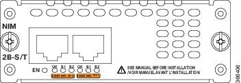
Figure 2 NIM-4B-S/T Front Panel
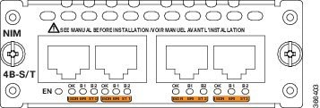

Note The faceplates show NIM-2B-S/T and NIM-4B-S/T for the 2- and 4-port ISDN BRI cards, respectively.
For an overview of Cisco Network Interface Modules used for Cisco access routers, see Cisco Network Interface and Modules for the Cisco 4000 Series Integrated Services Routers .
Accessibility
The NIMs can be configured using the Cisco command-line interface (CLI). The CLI conforms to code 508 because it is text based and it relies on a keyboard for navigation. All functions of the router can be configured and monitored through the CLI.
For a complete list of guidelines and Cisco products’ adherence to accessibility, see Cisco Accessibility Products at the following URL:
https://www.cisco.com/web/about/responsibility/accessibility/products
Platform Support for Cisco NIM-2B-S/T and NIM-4B-S/T
The NIM-2B-S/T and NIM-4B-S/T NIMs are supported on these Cisco router platforms:
Safety Warnings
Warning Read the installation instructions before using, installing or connecting the system to the power source. Statement 1004
Warning To avoid electric shock, do not connect safety extra-low voltage (SELV) circuits to telephone-network voltage (TNV) circuits. LAN ports contain SELV circuits, and WAN ports contain TNV circuits. Some LAN and WAN ports both use RJ-45 connectors. Use caution when connecting cables. Statement 1021
Warning Only trained and qualified personnel should be allowed to install, replace, or service this equipment. Statement 1030
Warning Do not use this product near water; for example, near a bathtub, wash bowl, kitchen sink or laundry tub, in a wet basement, or near a swimming pool. Statement 1035
Warning Never install telephone jacks in wet locations unless the jack is specifically designed for wet locations. Statement 1036
Warning Never touch uninsulated telephone wires or terminals unless the telephone line has been disconnected at the network interface. Statement 1037
Warning Avoid using a telephone (other than a cordless type) during an electrical storm. There may be a remote risk of electric shock from lightning. Statement 1038
Warning To report a gas leak, do not use a telephone in the vicinity of the leak. Statement 1039
Warning Ultimate disposal of this product should be handled according to all national laws and regulations. Statement 1040
Warning Before opening the unit, disconnect the telephone-network cables to avoid contact with telephone-network voltages. Statement 1041
Warning No user-serviceable parts inside. To avoid risk of electric shock, do not open. Statement 1073
Warning Installation of the equipment must comply with local and national electrical codes. Statement 1074
NIM-2B-S/T and NIM-4B-S/T LEDs
Figure 1 shows the NIM-2B-S/T and Figure 2 shows the NIM-4B-S/T LEDs. The ISDN BRI S/T NIMs have LEDs associated with an interface. These LEDs indicate call activity on the two ISDN BRI B channels, described in Table 1 .
Prerequisites for Connecting ISDN BRI S/T NIMs to a Network
This section describes the preparation necessary before connecting an ISDN BRI S/T NIM to the network. Before connecting a NIM to the network, ensure that the NIM is installed in the router, the equipment is properly grounded, and you have the proper cables for connecting the NIM to the network.
Install a Cisco ISDN BRI S/T
Install the Cisco ISDN BRI S/T NIM according to the instructions in Installing Cisco Interface Cards in Cisco Access Routers .
Grounding
Ensure that the equipment you are working with is properly grounded according to the instruction in Installing Cisco Interface Cards in Cisco Access Routers .
Cables
Use a straight-through RJ-45-to-RJ-45 cable (not included) to connect an ISDN BRI S/T NIM to a network.
Warning Hazardous network voltages are present in WAN ports regardless of whether power to the unit is OFF or ON. To avoid electric shock, use caution when working near WAN ports. When detaching cables, detach the end away from the unit first. Statement 1026
Connect NIM-2B-S/T and NIM-4B-S/T to a Network
To connect an ISDN BRI S/T NIM to a network (NT1), use a straight-through RJ-45-to-RJ-45 cable. (See Figure 3.) These ports are color-coded orange.
Figure 3 Connecting an ISDN BRI S/T port to an NT1 Device
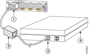
To connect an ISDN BRI S/T to a network, follow these steps:
Step 1 Connect one end of a straight-through RJ-45-to-RJ-45 cable to the RJ-45 port on the ISDN BRI S/T.
Step 2 Connect the other end of the RJ-45-to-RJ-45 cable to the external termination resistor (100ohm).
Step 3 Connect the other end of the cable to the NT1 device, as shown in Figure 3.
Step 4 Follow the instructions in the documentation that comes with the NT1 device to connect the NT1 device to the ISDN wall jack.
Step 5 Turn on power to the router.
Connect Point-to-Multipoint S Interface
To connect one or more basic ISDN ports, use the ISDN BRI interface to connect the point-to-multipoint S interface.
Note The resistor is added to the bus at the furthest point from the NT1.
Note Point-to-multipoint support is permitted only when no bus loop power is consumed by any endpoint on the bus. The ISDN BRI S/T does not consume S-bus loop power.
Step 1 Connect one end of a straight-through RJ-45-to-RJ-45 cable to the RJ-45 port on the ISDN BRI S/T.
Step 2 Connect the other end of the RJ-45 cable to up to 7 other Traffic Engineering (TE) interfaces and external terminating resistor.
Figure 4 Connecting Point-to-Multipoint

Related Documentation
Related documentation is available on Cisco.com.
- Cisco Network Modules, Server Modules, and Interface Cards Regulatory Compliance and Safety Information
- “Configuring ISDN BRI” chapter of the Cisco IOS Dial Technologies Configuration Guide for your Cisco IOS software release
Obtain Documentation and Submit a Service Request
For information on obtaining documentation, using the Cisco Bug Search Tool (BST), submitting a service request, and gathering additional information, see What’s New in Cisco Product Documentation .
To receive new and revised Cisco technical content directly to your desktop, you can subscribe to the What’s New in Cisco Product Documentation RSS feed . The RSS feeds are a free service.
Cisco and the Cisco logo are trademarks or registered trademarks of Cisco and/or its affiliates in the U.S. and other countries. To view a list of Cisco trademarks, go to this URL: www.cisco.com/go/trademarks . Third-party trademarks mentioned are the property of their respective owners. The use of the word partner does not imply a partnership relationship between Cisco and any other company. (1721R)
 Feedback
Contact Cisco
- Open a Support Case

- (Requires a Cisco Service Contract)