Configuration Guide for Cisco NCS 1001, IOS XR Release 25.x.x
Bias-Free Language
The documentation set for this product strives to use bias-free language. For the purposes of this documentation set, bias-free is defined as language that does not imply discrimination based on age, disability, gender, racial identity, ethnic identity, sexual orientation, socioeconomic status, and intersectionality. Exceptions may be present in the documentation due to language that is hardcoded in the user interfaces of the product software, language used based on RFP documentation, or language that is used by a referenced third-party product. Learn more about how Cisco is using Inclusive Language.
identifies the optical controller that you configure or display, and
uses values such as 0/1/0/1 for a specific controller location.
Controller identifier fields
Table 1. Controller identifier fields
Field
Value
Rack
0
Slot
1 to 3. These slots support pluggable optical modules.
Instance
0
Port
Depends on the specific pluggable optical module.
OTS controllers
An Optical Transport Section (OTS) controller is an optical interface controller that
stores the optical parameters for the OTS interfaces,
exposes parameters based on hardware capabilities such as photodiode, variable optical attenuator (VOA), amplifier, optical
channel monitor (OCM), and
supports receive and transmit section parameters when the hardware supports them.
When an OTS controller is created, each hardware capability is enabled or disabled. For example, when a photodiode is present,
the OTS controller can read the total optical power.
You can configure OTS parameters such as low power threshold, VOA attenuation set point, amplifier gain range, amplifier tilt,
amplifier gain set point, channel power, and safety control mode. OTS interface descriptions cannot be added in the same way
as descriptions on the optical amplifier module.
Configuration parameters of OTS controller
Table 2. Configuration parameters of OTS controller
Parameter
Description
Hardware capability
Range
Default
Notes
rx-low-threshold (0.1 dBm)
Low receive power threshold.
Photodiode
-400 to +300
-40.0
tx-low-threshold (0.1 dBm)
Low transmit power threshold.
Photodiode
-400 to +300
-20.0
rx-voa-attenuation (0.1 dBm)
RX VOA attenuation set point.
VOA
0 to 200
0.0
tx-voa-attenuation (0.1 dBm)
TX VOA attenuation set point.
VOA
0 to 200
0.0
ampli-control-mode
Amplifier control mode.
Amplifier
automatic, manual
automatic
The automatic value is compatible only when the grid is specified through the hw-module configuration.
ampli-gain-range
Amplifier gain range.
Amplifier
normal, extended
normal
The amplifier gain range is configurable only when the controller is in shutdown state.
ampli-gain (0.1 dBm)
Amplifier gain set point.
Amplifier
0 to 500
0.0
The actual range depends on the amplifier gain range.
ampli-tilt (0.1 dBm)
Amplifier tilt.
Amplifier
-50 to +50
0.0
channel-power-max-delta (0.1 dBm)
Maximum difference among measured channel powers.
Amplifier
0–200
3.0
ampli-channel-power (0.1 dBm)
Amplifier per-channel power set point.
Amplifier
-400 to +300
0.0
osri
Optical safety remote interlock.
Amplifier
on, off
off
When OSRI is enabled, the laser is deactivated. When OSRI is disabled, the laser is activated.
safety-control-mode
Safety control mode.
Amplifier
auto, disabled
auto
When safety control mode is disabled, amplifier optical power is less than 20 dB for safety.
Configure an OTS controller
Configure OTS controller parameters when the optical interface hardware supports the required capability.
Use the controller identifier in Rack/Slot/Instance/Port format. For parameter ranges and defaults, see OTS controllers.
Procedure
Step 1
Enter configuration mode.
configure
Step 2
Use the controller ots command to enter the OTS controller configuration mode.
controller otsrack/slot/instance/port
Step 3
Configure the required OTS parameters.
Use the commands that apply to the hardware capability in this sequence.
rx enable
rx-low-thresholdvalue
tx enable
tx-low-thresholdvalue
rx-voa-attenuationvalue
tx-voa-attenuationvalue
ampli-control-mode { automatic | manual}
ampli-gain-range { normal | extended}
ampli-gainvalue
ampli-tiltvalue
ampli-channel-powervalue
channel-power-max-deltavalue
osri { on | off}
safety-control-mode { auto | disabled}
Example:
In this sample, the amplifier gain range is set to extended and amplifier gain set point is set to 29.0 dB.
configure
  controller ots 0/3/0/0
  ampli-gain-range extended
  ampli-gain 290
  commit
end
In this sample, the safety control mode of the pre-amplifier is set to auto.
configure
  controller ots 0/3/0/0
  safety-control-mode auto
  commit
end
In this sample, the safety control mode of the booster amplifier is set to disabled.
configure
  controller ots 0/3/0/1
  safety-control-mode disabled
  commit
end
Step 4
Commit the configuration.
commit
Step 5
Exit configuration mode.
end
The OTS controller uses the configured optical parameter values.
Display OTS controller parameters
The show controllers command displays all the configuration parameters, performance monitoring thresholds, and alarms if no optional keyword is
provided. If you include the summary keyword, the command displays receive and transmit power values and minimal information to understand port status.
Procedure
Display the OTS controller parameters.
show controllerscontroller-type rack/slot/instance/port [ summary]
Use * as a wildcard to display all the controllers associated with a slot, such as show controllers ots 0/1/0/* summary.
Example:
RP/0/RP0/CPU0:ios#show controllers ots 0/3/0/1
Wed Aug 23 09:08:27.962 UTC

 Controller State: Up

 Transport Admin State: In Service

 Port Type: Line

 Laser State: Off

 Optics Status::


 Alarm Status:
 -------------
 Detected Alarms:
 RX-LOC

 Alarm Statistics:
 -----------------
 LOW-RX-PWR = 0
 LOW-TX-PWR = 0
 RX-LOS-P = 0
 RX-LOC = 1
 AMPLI-GAIN-DEG-LOW = 0
 AMPLI-GAIN-DEG-HIGH = 0
 AUTO-LASER-SHUT = 0
 AUTO-POW-RED = 89
 AUTO-AMPLI-CTRL-DISABLED = 0
 AUTO-AMPLI-CFG-MISMATCH = 0
 SWITCH-TO-PROTECT = 0
 AUTO-AMPLI-CTRL-RUNNING = 0

 Parameter Statistics:
 ---------------------
 TX Power = -40.00 dBm
 RX Power = -40.00 dBm
 Ampli Gain = -1.00 dB
 Ampli Tilt = 0.00
 Total TX Power = -40.00 dBm
 Total RX Power = -40.00 dBm

 Configured Parameters:
 -------------
 Rx Low Threshold = -25.0 dBm
 Tx Low Threshold = -20.0 dBm
 Ampli Gain = 1.00 dB
 Ampli Tilt = 0.00
 Ampli Channel power = 0.00 dBm
 Channel Power Max Delta = 3.00 dBm
 Ampli Control mode = Manual
 Ampli Gain Range = Normal
 Ampli Safety Control mode = auto
 Osri = OFF
RP/0/RP0/CPU0:ios#show controllers ots 0/1/0/1
Controller State: Down

Transport Admin State: In Service

Port Type: Line

Laser State: Apr

Optics Status::


         Alarm Status:
         -------------
         Detected Alarms:
                 AUTO-POW-RED

         Alarm Statistics:
         -----------------
         LOW-RX-PWR = 0
         LOW-TX-PWR = 0
         RX-LOS-P = 0
         RX-LOC = 1
         AMPLI-GAIN-DEG-LOW = 0
         AMPLI-GAIN-DEG-HIGH = 0
         AUTO-LASER-SHUT = 0
         AUTO-POW-RED = 1
         AUTO-AMPLI-CTRL-DISABLED = 0
         AUTO-AMPLI-CFG-MISMATCH = 0
         SWITCH-TO-PROTECT = 0
         AUTO-AMPLI-CTRL-RUNNING = 0

         Parameter Statistics:
         ---------------------
         TX Power = -40.00 dBm
         RX Power = -11.90 dBm
         Ampli Gain = -1.00 dB
         Ampli Tilt = -90.00
         Total TX Power = 7.99 dBm
         Total RX Power = -11.90 dBm
         Ampli Gain Range = Normal
         Ampli Safety Control mode = disabled
         Osri = OFF
         TX Enable = Enabled
         RX Enable = Enabled
         RX Span Loss = N/A
         TX Span Loss = N/A
         Rx Low Threshold Current = -25.0 dBm
         Back Reflection = -6.40 dBm

         Configured Parameters:
         -------------
         Rx Low Threshold = -25.0 dBm
         Tx Low Threshold = -20.0 dBm
         Ampli Gain = 12.00 dB
         Ampli Tilt = 0.00
         Ampli Channel power = 0.00 dBm
         Channel Power Max Delta = 3.00 dBm
         Ampli Channel Psd = 31.250 nW/MHz
         Rx Low Threshold Psd = 0.099 nW/MHz
         Ampli Control mode = Manual
         Ampli Safety Control mode = disabled
         Osri = OFF
         TX Enable = Enabled
         RX Enable = Enabled
The Back Reflection parameter, in 0.1 dBm, is raised only on port 1. This parameter is raised on the line TX port of the booster
amplifier.
The command output shows OTS controller state, alarms, statistics, and configured parameter values.
Span loss calculation
Span loss calculation is an automatic software function that
calculates span losses between NCS 1001 systems,
uses transmit and receive total power on EDFA ports, and
supports protected or nonprotected linear topologies, with or without intermediate inline amplifier (ILA) nodes.
The feature is available for the OTS controller and can be enabled or disabled through the hw-module configuration. The calculation runs automatically every five minutes and when there is a configuration change.
Calculation methods and parameters
Span loss calculation first uses remote node configuration and, if unavailable, uses OSC through OSPF.
The show controllers ots command displays these span loss parameters for EDFA cards:
RX Span Loss
TX Span Loss
Limitation
Span loss calculation considers total power at the transmit end and receive end on EDFA ports. If the PSM card is connected
to the span, such as in a path-protection topology, the span boundaries are assumed to be the closer EDFA ports.
Configure span loss calculation
Configure span loss calculation across the local and remote NCS 1001 systems that participate in the optical span.
Table 3. Feature History
Feature Name
Release Information
Description
IPv6 Support for Span Loss Calculation
Cisco IOS XR Release 7.10.1
You can now perform span loss calculations on IPv6 spans connecting two NCS 1001 nodes. As a result, the advantages of larger
address space can be leveraged by configuring IPv6 addresses on the management interfaces used for communication between the
two nodes.
Starting with Cisco IOS XR Release 7.10.1, span loss calculation supports IPv6 addresses in addition to IPv4 addresses. The
IPv6 addresses must be configured on the management interfaces of IPv6 enabled NCS 1001 nodes.
The feature uses DCN or OSC (OSPF) so NCS systems can exchange power measurements needed to calculate span losses. In both
cases, you must enable the feature and specify the node type (TERM or ILA) on each system.
Note
Configure either IPv4 or IPv6, but not both, for span loss calculation.
Span loss calculation with IPv6 is not supported on OSC management interfaces of NCS 1001 nodes. Even with OSPFv3, neighbor
discovery returns the IPv4 router ID instead of the IPv6 router ID. This prevents automatic IPv6 address resolution.
Use IPv6 only when span loss calculation is not using IPv4 for the same span. IPv6 span loss calculation is not supported
on the OSC management interfaces.
Procedure
Step 1
Enter configuration mode.
configure terminal
Step 2
Configure the local and remote IPv6 span loss endpoints.
The system automatically triggers the first calculation after at least 5 minutes.
Procedure
Trigger span loss calculation for the specified slot.
hw-module slotnspan-loss calculation
The system starts a span loss calculation for the specified slot.
Span loss calculation use cases
Use these examples to identify how local node, remote node, and remote slot values change by topology.
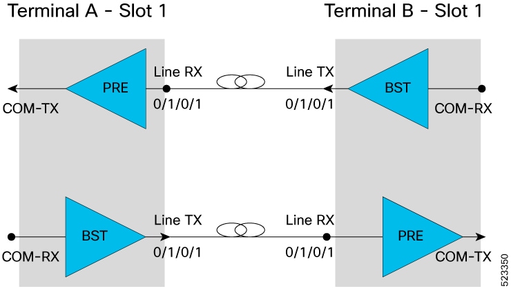
Terminal-to-terminal use case
Terminal node A (IP address: 192.0.2.144(IPv4) or 2001:DB8:4491:2000::229:144(IPv6)) with a EDFA in slot number 1 connected
to the EDFA in slot number 1 of Terminal node B (IP address: 192.0.2.146(IPv4) or 2001:DB8:4491:2000::229:146(IPv6)).
Figure 1. Terminal-to-terminal span loss topology
For each EDFA module, it is necessary to configure remote node feature and the span loss using these CLI commands:
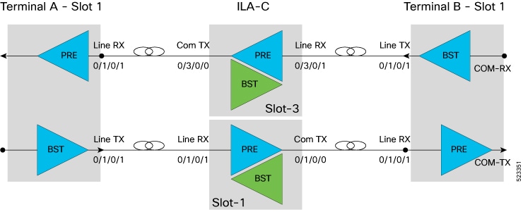
Terminal A (IP address: 192.0.2.144(IPv4) or 2001:DB8:4491:2000::229:144(IPv6)) with a EDFA in slot number 1 with COM-TX port
connected to LINE-RX EDFA in slot 1 ILA-C (IP address: 192.0.2.145(IPv4) or 2001:DB8:4491:2000::229:145(IPv6))
ILA C with a EDFA in slot number 1 with COM-TX port connected to LINE-RX EDFA in slot 1 of Terminal B (IP address: 192.0.2.146
(IPv4) or 2001:DB8:4491:2000::229:146)
ILA C with a EDFA in slot number 3 with COM-TX port connected to LINE-RX EDFA in slot 1 Terminal A
Terminal B with a EDFA in slot number 1 with COM-TX port connected to LINE-RX EDFA in slot 3 ILA.
Figure 2. Terminal-to-ILA-to-terminal span loss topology
After the feature is enabled and the first calculation runs, the show controllers ots command displays RX Span Loss and TX Span Loss. These values are calculated from the difference between TX Total Power and
RX Total Power at the span edge.
Procedure
Step 1
Display span loss for a TERM node line port.
Example:
#show controllers ots 0/1/0/1
RX Span Loss = 15.20 dB
TX Span Loss = 14.80 dB
Step 2
For an ILA node, display RX Span Loss on the line port and TX Span Loss on the COM port.
Example:
#show controllers ots 0/3/0/1
RX Span Loss = 12.40 dB
#show controllers ots 0/3/0/0
TX Span Loss = 11.90 dB
Dual IP addresses
Dual independent XR interfaces are management Ethernet interfaces that
connect two Ethernet interfaces to different switches in different or same subnets,
use separate MGMT RJ45 and optical SFP MGMT ports to the CPU from Release 6.5.1, and
support management connectivity through MgmtEth0/RP0/CPU0/0 and MgmtEth0/RP0/CPU0/1.
Management Ethernet interfaces
MgmtEth0/RP0/CPU0/0 represents the RJ45 port.
MgmtEth0/RP0/CPU0/1 represents the SFP port.
iPXE is not supported at power-on over the new optical interface. If you upgraded from a previous release and used only SFP,
management connectivity may be lost. In this case, configure the system through the console port. Before using both interfaces,
upgrade the BIOS and reload the 0/RP0 location.
An Optical Transport Section Optical Channel (OTS OCH) controller is a channel-level controller that
represents the optical channel monitor (OCM) device on an OTS optical interface,
provides channel granularity over the OTS interface, and
stores wavelength information with controller numbers that start at 1 and match ITU channel identifiers.
The system creates 48 OTS OCH controllers for a 100 GHz grid and 96 OTS OCH controllers for a 50 GHz grid.
Configuration parameters for OTS OCH controllers
Table 4. Configuration parameters for OTS OCH controllers
Parameter
Description
Hardware capability
Range
Default
rx-low-threshold (0.1 dBm)
Low receive power threshold.
OCM
-500 to +300
-25.0
tx-low-threshold (0.1 dBm)
Low transmit power threshold.
OCM
-500 to +300
-25.0
Configure an OTS OCH controller
Use the controller identifier for the OTS OCH controller that you want to configure.
Procedure
Step 1
Enter configuration mode.
configure
Step 2
Use the controller ots-och command to enter OTS OCH controller configuration mode.
controller ots-ochrack/slot/instance/port
Step 3
Configure the low-power thresholds.
rx-low-thresholdvalue
tx-low-thresholdvalue
Step 4
Commit the configuration.
commit
Step 5
Exit the configuration mode.
end
Example:
configure
  controller ots-och 0/1/0/0
  rx-low-threshold -30
  tx-low-threshold -35
  commit
end
Display OTS OCH controller parameters
The show controllers command displays all the configuration parameters, performance monitoring thresholds, and alarms if no optional keyword is
provided. If you include the summary keyword, the command displays RX and TX power values and wavelength details.
Procedure
Display OTS OCH controller parameters.
show controllerscontroller-type rack/slot/instance/port/channel-number [ summary]
Use * as a wildcard to display all OTS OCH controllers associated with an OTS controller, such as show controllers ots-och 0/1/0/* summary.
Example:
Fri Feb 24 13:20:18.456 CET

 Controller State: Up

 Transport Admin State: Maintenance

 Port Type: Line

 Laser State: Unnown

 Optics Status::


         Alarm Status:
         -------------
         Detected Alarms:None


         Alarm Statistics:
         -----------------
          LOW-RX-PWR = 0
          LOW-TX-PWR = 0


         Parameter Statistics:
         ---------------------
         TX Power = -3.30 dBm
         RX Power = -21.10 dBm
         TX psd = 13.586 nW/MHz
         RX psd = 0.220 nW/MHz
         Channel Central Frequency = 196100.0 GHz
         Channel Width = 50.0 GHz

         Configured Parameters:
         -------------
         Rx Low Threshold = -25.0 dBm
         Tx Low Threshold = -25.0 dBm
Fri Oct  9 10:37:50.109 CEST

 Port               Type    Status       TX Power     RX Power      TX psd        RX psd    Central Frequency Channel Width
                                             (dBm)        (dBm)      nW/MHz)     (nW/MHz)       (GHz)             (GHz)
 -----------------  ----    -------      ---------    ---------     ---------     -------     ---------------   -------------
  Ots-Och0_2_0_0_1    Com      N/A      -18.30        -19.30         0.392         0.333        196100.0          75.0
  Ots-Och0_2_0_0_2    Com      N/A      -19.10        -19.80         0.094         0.068        196025.0          75.0
  Ots-Och0_2_0_0_3    Com      N/A      -18.00        -18.90         0.450         0.392        195950.0          75.0
  Ots-Och0_2_0_0_4    Com      N/A      -16.90        -17.60         0.318         0.290        195875.0          75.0
  Ots-Och0_2_0_0_5    Com      N/A      -18.10        -19.20         0.326         0.290        195800.0          75.0
  Ots-Och0_2_0_0_6    Com      N/A      -19.50        -19.90         0.059         0.041        195725.0          75.0
  Ots-Och0_2_0_0_7    Com      N/A      -18.60        -19.00         0.471         0.450        195650.0          75.0
  Ots-Och0_2_0_0_8    Com      N/A      -17.00        -17.60         0.304         0.318        195575.0          75.0
  Ots-Och0_2_0_0_9    Com      N/A      -18.50        -19.20         0.318         0.297        195500.0          75.0
 Ots-Och0_2_0_0_10    Com      N/A      -17.60        -18.00         0.318         0.297        195425.0          75.0
 Ots-Och0_2_0_0_11    Com      N/A      -18.50        -19.00         0.401         0.374        195350.0          75.0
 Ots-Och0_2_0_0_12    Com      N/A      -17.70        -18.00         0.188         0.253        195275.0          75.0
 Ots-Och0_2_0_0_13    Com      N/A      -18.90        -19.70         0.304         0.271        195200.0          75.0
 Ots-Och0_2_0_0_14    Com      N/A      -20.50        -20.90         0.242         0.236        195125.0          75.0
 Ots-Och0_2_0_0_15    Com      N/A      -24.00        -27.40         0.031         0.011        195050.0          75.0
 Ots-Och0_2_0_0_16    Com      N/A      -17.80        -18.40         0.215         0.242        194975.0          75.0
 Ots-Och0_2_0_0_17    Com      N/A      -18.50        -19.10         0.318         0.290        194900.0          75.0
 Ots-Och0_2_0_0_18    Com      N/A      -16.90        -17.30         0.333         0.297        194825.0          75.0
 Ots-Och0_2_0_0_19    Com      N/A      -18.10        -18.90         0.410         0.366        194750.0          75.0
 Ots-Och0_2_0_0_20    Com      N/A      -17.00        -17.50         0.357         0.366        194675.0          75.0
 Ots-Och0_2_0_0_21    Com      N/A      -18.50        -19.30         0.326         0.290        194600.0          75.0
 Ots-Och0_2_0_0_22    Com      N/A      -17.20        -17.70         0.259         0.265        194525.0          75.0
 Ots-Och0_2_0_0_23    Com      N/A      -18.40        -19.10         0.410         0.392        194450.0          75.0
 Ots-Och0_2_0_0_24    Com      N/A      -16.50        -16.90         0.450         0.430        194375.0          75.0
 Ots-Och0_2_0_0_25    Com      N/A      -24.30        -28.90         0.040         0.000        194300.0          75.0
 Ots-Och0_2_0_0_26    Com      N/A      -16.60        -16.90         0.326         0.297        194225.0          75.0
 Ots-Och0_2_0_0_27    Com      N/A      -18.10        -18.70         0.420         0.410        194150.0          75.0
 Ots-Och0_2_0_0_28    Com      N/A      -16.80        -16.90         0.383         0.392        194075.0          75.0
 Ots-Och0_2_0_0_29    Com      N/A      -19.10        -19.80         0.333         0.311        194000.0          75.0
 Ots-Och0_2_0_0_30    Com      N/A      -16.90        -17.10         0.284         0.311        193925.0          75.0
 Ots-Och0_2_0_0_31    Com      N/A      -18.70        -19.20         0.374         0.383        193850.0          75.0
 Ots-Och0_2_0_0_32    Com      N/A      -17.20        -17.40         0.374         0.392        193775.0          75.0
 Ots-Och0_2_0_0_33    Com      N/A      -18.60        -19.10         0.410         0.410        193700.0          75.0
 Ots-Och0_2_0_0_34    Com      N/A      -17.30        -17.60         0.311         0.311        193625.0          75.0
 Ots-Och0_2_0_0_35    Com      N/A      -18.90        -19.10         0.392         0.401        193550.0          75.0
 Ots-Och0_2_0_0_36    Com      N/A      -18.00        -18.20         0.265         0.265        193475.0          75.0
 Ots-Och0_2_0_0_37    Com      N/A      -19.50        -20.00         0.304         0.318        193400.0          75.0
 Ots-Och0_2_0_0_38    Com      N/A      -17.80        -17.90         0.265         0.311        193325.0          75.0
 Ots-Och0_2_0_0_39    Com      N/A      -18.60        -19.00         0.383         0.392        193250.0          75.0
 Ots-Och0_2_0_0_40    Com      N/A      -16.80        -17.00         0.383         0.392        193175.0          75.0
 Ots-Och0_2_0_0_41    Com      N/A      -18.70        -19.10         0.440         0.450        193100.0          75.0
 Ots-Och0_2_0_0_42    Com      N/A      -16.80        -17.10         0.374         0.349        193025.0          75.0
 Ots-Och0_2_0_0_43    Com      N/A      -18.90        -19.40         0.401         0.420        192950.0          75.0
 Ots-Och0_2_0_0_44    Com      N/A      -17.00        -17.40         0.450         0.440        192875.0          75.0
 Ots-Och0_2_0_0_45    Com      N/A      -18.50        -18.80         0.392         0.392        192800.0          75.0
 Ots-Och0_2_0_0_46    Com      N/A      -17.40        -17.60         0.284         0.271        192725.0          75.0
 Ots-Och0_2_0_0_47    Com      N/A      -24.40        -31.50         0.064         0.000        192650.0          75.0
 Ots-Och0_2_0_0_48    Com      N/A      -19.20        -19.60         0.410         0.430        192575.0          75.0
 Ots-Och0_2_0_0_49    Com      N/A      -18.70        -19.40         0.392         0.383        192500.0          75.0
 Ots-Och0_2_0_0_50    Com      N/A      -17.10        -17.60         0.374         0.326        192425.0          75.0
 Ots-Och0_2_0_0_51    Com      N/A      -19.10        -19.50         0.401         0.401        192350.0          75.0
 Ots-Och0_2_0_0_52    Com      N/A      -20.40        -20.50         0.357         0.311        192275.0          75.0
 Ots-Och0_2_0_0_53    Com      N/A      -24.70        -34.20         0.042         0.000        192200.0          75.0
 Ots-Och0_2_0_0_54    Com      N/A      -17.60        -18.10         0.201         0.236        192125.0          75.0
 Ots-Och0_2_0_0_55    Com      N/A      -18.50        -19.10         0.401         0.392        192050.0          75.0
 Ots-Och0_2_0_0_56    Com      N/A      -17.20        -17.80         0.341         0.284        191975.0          75.0
 Ots-Och0_2_0_0_57    Com      N/A      -25.60        -30.40         0.050         0.000        191900.0          75.0
 Ots-Och0_2_0_0_58    Com      N/A      -17.40        -17.90         0.220         0.188        191825.0          75.0
 Ots-Och0_2_0_0_59    Com      N/A      -19.40        -20.40         0.333         0.290        191750.0          75.0
 Ots-Och0_2_0_0_60    Com      N/A      -27.10        -38.90         0.023         0.000        191675.0          75.0
 Ots-Och0_2_0_0_61    Com      N/A      -26.00        -38.90         0.031         0.000        191600.0          75.0
 Ots-Och0_2_0_0_62    Com      N/A      -19.50        -20.10         0.133         0.045        191525.0          75.0
 Ots-Och0_2_0_0_63    Com      N/A      -19.20        -19.90         0.401         0.392        191450.0          75.0
 Ots-Och0_2_0_0_64    Com      N/A      -17.30        -17.60         0.333         0.333        191375.0          75.0
From Release 7.3.1, the Central Frequency and Channel Width columns include a decimal place.
LLDP over OSC
Use LLDP over OSC to gather point-to-point local link discovery information about neighboring devices in the network.
Feature history
Table 5. Feature history
Feature name
Release
Description
LLDP over OSC
Cisco IOS XR Release 7.3.1
LLDP is supported on the OSC management interface for point-to-point local link discovery through the OSC channel. It enables
you to gather information about neighboring devices in the network.
Neighbor output
The show lldp neighbors command displays OSC interface neighbors after LLDP is enabled on an OSC interface.
RP/0/RP0/CPU0:MYS-130#show lldp neighbors
Capability codes:
(R) Router, (B) Bridge, (T) Telephone, (C) DOCSIS Cable Device
(W) WLAN Access Point, (P) Repeater, (S) Station, (O) Other

Device ID  Local Intf             Hold-time  Capability  Port ID
MYS-131    MgmtEth0/RP0/OSC3/1    120        R           MgmtEth0/RP0/OSC1/0

 Feedback