|
Port
|
(Display only) Displays the port name.
|
—
|
|
Description
|
Type the description of the port.
|
—
|
|
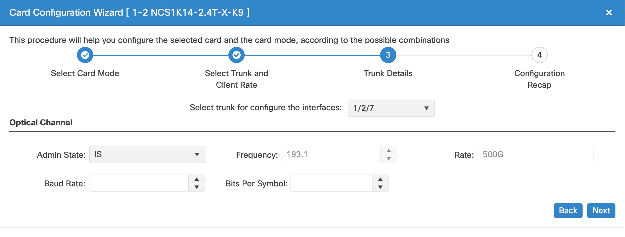
Admin State
|
Sets the port service state unless network conditions prevent the change.
|
-
Unlocked (ETSI)/ IS (ANSI)
-
Locked, disabled (ETSI)/ OOS, DSBLD (ANSI)
-
Locked, maintenance (ETSI)/ OOS, MT (ANSI)
-
Unlocked, automaticInService (ETSI)/ IS, AINS (ANSI)
|
|
Service State
|
Displays the service state.
|
—
|
|
Reach
|
Indicates the distance from one node to another node.
|
-
Auto Provision
-
List of reach values
|
|
SD FEC
|
Indicates the standard FEC.
|
-
SD_FEC_15_DE_OFF
-
SD_FEC_15_DE_ON
-
SD_FEC_20
-
SD_FEC_25_DE_OFF
-
SD_FEC_25_DE_ON
-
SD_FEC_7
|
|
Tx Power (dBm)
|
Sets the Tx power on the trunk port.
|
The range is –10.0 to 0.25 dBm.
|
|
PSM Info
|
When enabled on a TXP or MXP trunk port that is connected to a PSM card, it allows fast switching on the cards.
|
|
|
Frequency (THz)
|
Sets the frequency in THz
|
-
|
|
Wavelength (nm)
|
Displays the wavelength, which is set based on the Frequency.
|
-
|
|
Tx Shutdown
|
(Display only)
|
|
|
Width (GHz)
|
(Display only)
|
-
|
|
CD (Working Range) High (ps/nm)
|
Sets the threshold for maximum chromatic dispersion.
|
-
|
|
CD (Working Range) Low (ps/nm)
|
Sets the threshold for minimum chromatic dispersion.
|
-
|
|
Target Power
|
Sets the Rx VOA target power.
|
Note
|
You cannot configure this parameter if Fixed Ratio is already configured.
|
|
|
|
Fixed Ratio
|
Sets the Rx VOA fixed ratio.
|
Note
|
You cannot configure this parameter if Target Power is already configured.
|
|
|
|
Rate
|
Displays the rate.
|
—
|


 Feedback