Cisco WAE UI Overview
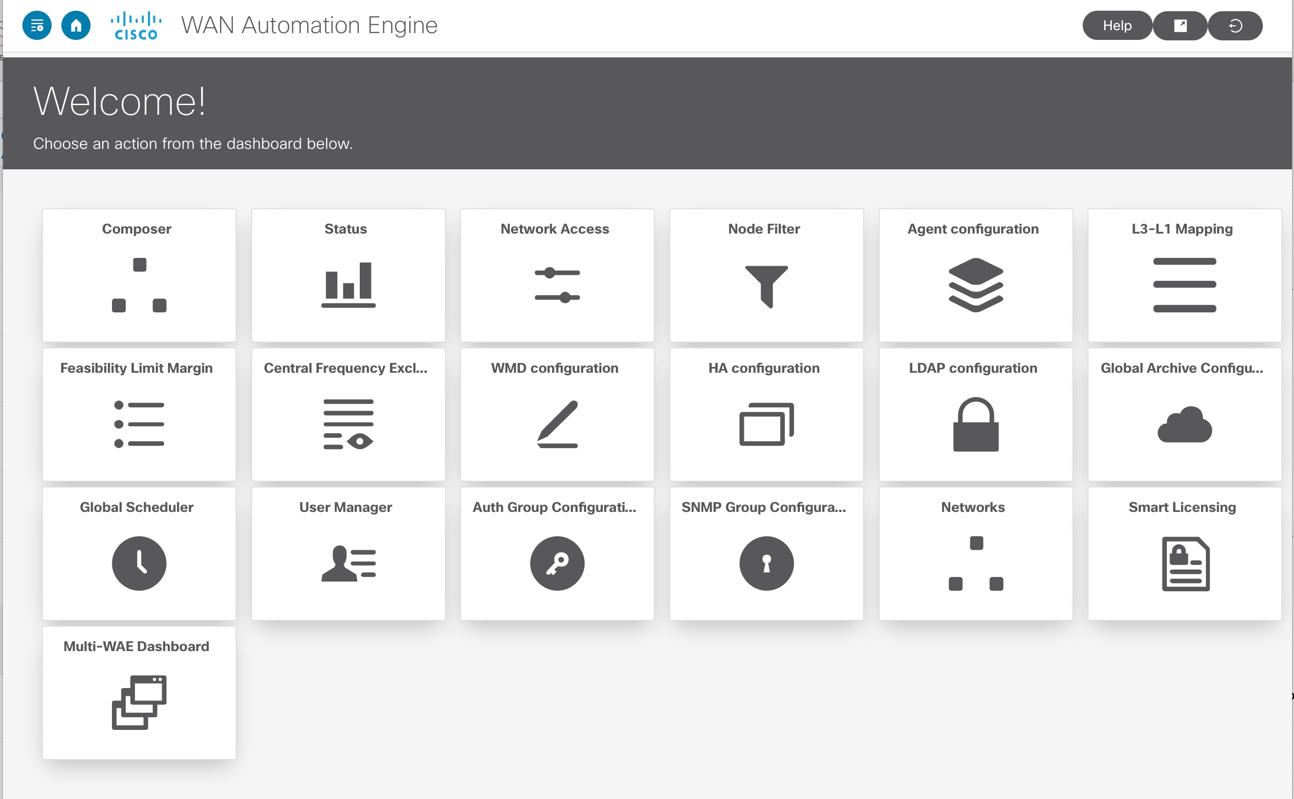
The Cisco WAE UI provides an easy-to-use configuration tool for device and network access, network model creation, user management, agent configuration, and so on.
For basic network model configuration we recommend starting with the Network Model Composer. You can also choose to perform certain operations using the Expert Mode or the Cisco WAE CLI. Regardless of the interface you use, the last committed configuration is saved.
 Note |
Make sure that only a single session is active per user. Multiple sessions per user can create issues and is not recommended. |
|
Icons |
Description |
For more information, see... |
||
|---|---|---|---|---|
 |
Returns you to the main Cisco WAE UI landing page. |
— |
||
|
Composer |
Opens the Network Model Composer, which lets you create and build a network model. |
|||
|
Status |
The Status Dashboard helps to identify processes that cause system leaks or processes that completely use the resources. |
|||
|
Network Access |
Opens the network access configuration page, which lets you configure global device and network credentials. |
|||
|
Node Filter |
Open Node Filter page which lets you to exclude or include individual nodes from collection. |
|||
|
Agent Configuration |
Opens the agent configuration page, which lets you create and modify agents. |
|||
|
L3-L1 Mapping |
Opens the L3-L1 mapping configuration page, which lets you create and modify L3-L1 node and circuit mappings for multilayer collection. |
|||
|
Feasibility Limit Margin |
Opens the feasibility limit margin configuration page, which lets you set the acceptable quality of the L1 circuit path. |
"L1 Circuit Wavelengths" topic in the Cisco WAE Design User Guide. |
||
|
Central Frequency Excludelists |
Opens the central frequency excludelist configuration page, which lets you define the list of frequency IDs that may not serve as central frequency IDs for L1 circuit paths. |
"L1 Circuit Wavelengths" and "Central Frequency ID Excludelist" topic in the Cisco WAE Design User Guide. |
||
|
WMD configuration |
Opens the WMD configuration page, which lets you view WMD options such as debugging, rpc and application subscriber connections, demands, and so on. To edit these options, use the Expert Mode or WAE CLI or WAE UI. |
|||
|
HA configuration |
Opens the high availability (HA) configuration page, which lets you designate which nodes are used for HA. |
|||
|
LDAP configuration |
Opens the LDAP configuration page, which lets you enable and configure LDAP details. |
|||
|
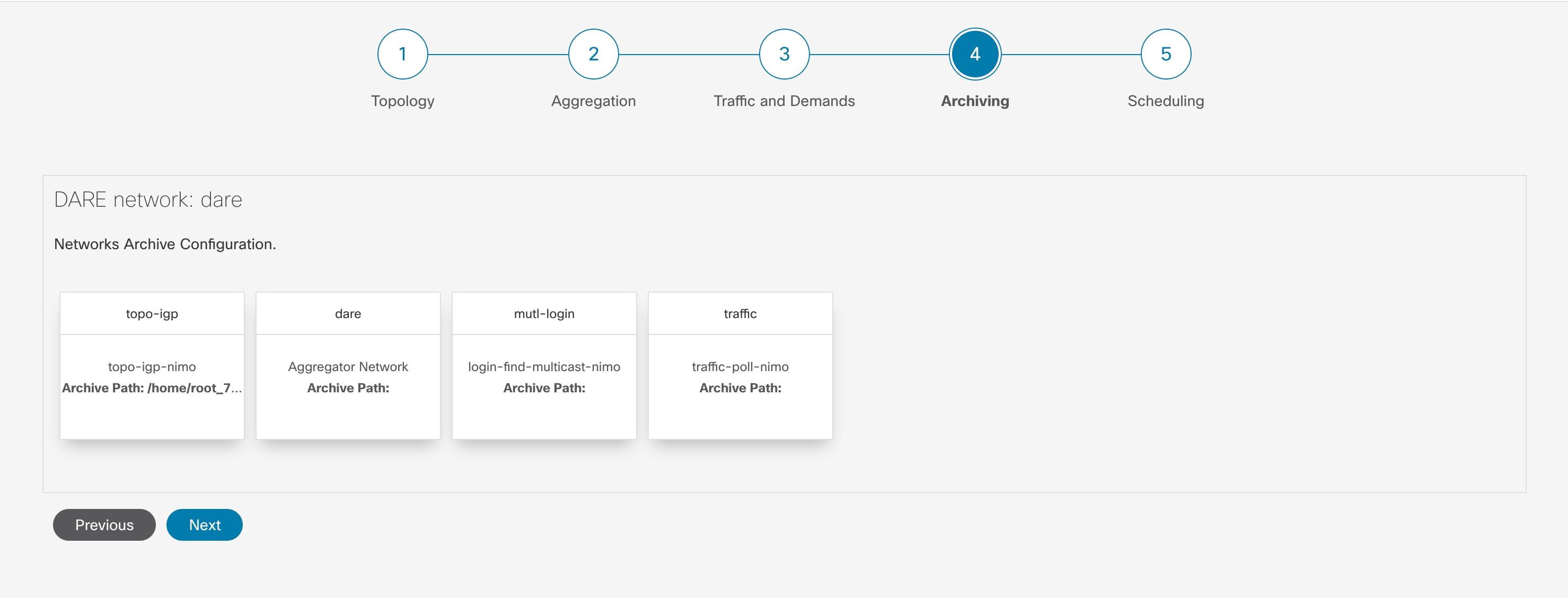
Global Archive Configuration |
Opens Global Archive page from where plan files can be downloaded. |
|||
|
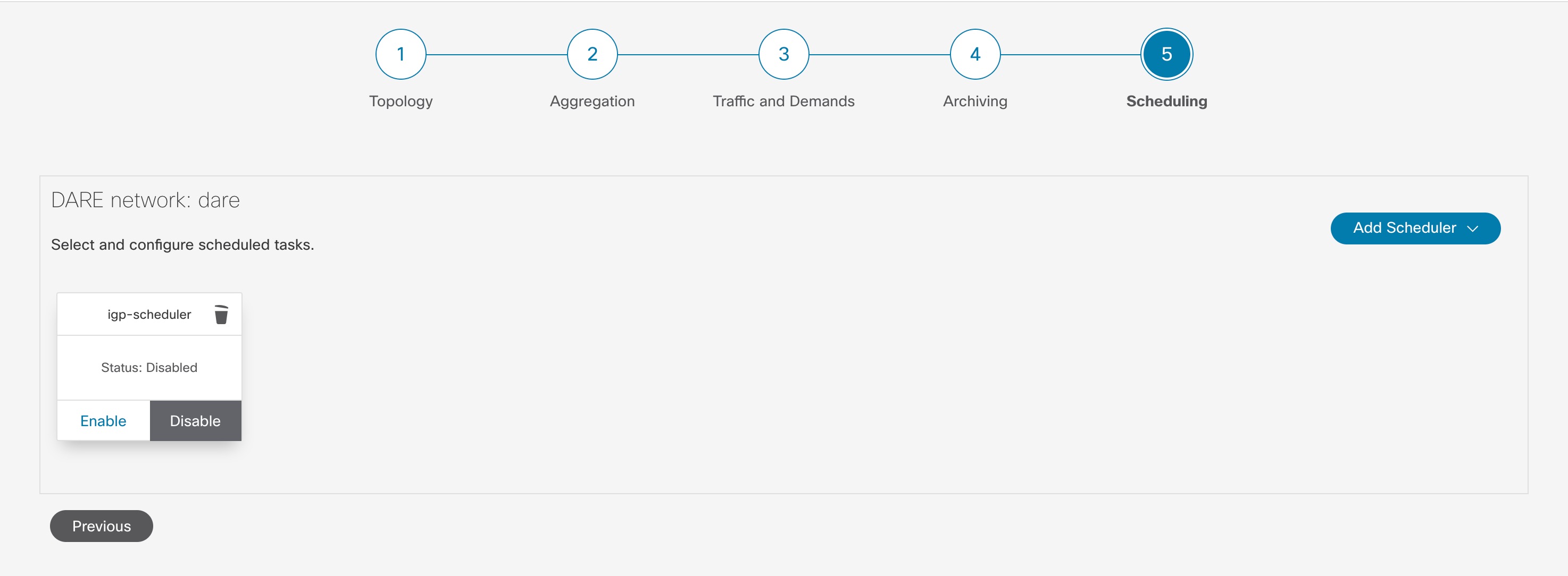
Global Scheduler |
Opens Global Scheduler page which lets you to create a scheduled task. |
|||
|
User Manager |
Opens the user management page, which lets you add, modify, and delete users. |
|||
|
Auth Group Configuration |
Opens Auth Group Configuration page which lets you create a new authorization group. |
|||
|
SNMP Group Configuration |
Opens SNMP Group Configuration page which lets you create a new SNMP group. |
Configure Network Access Using the Cisco WAE UI | ||
|
Networks |
Opens Networks page which lets you to create a standalone network. |
|||
|
Smart Licensing |
Opens Smart Licensing page that allows you to enable and register smart license for Cisco WAE. |
|||
|
Multi WAE Dashboard |
Opens Multi WAE Dashboard page that provides details related to different WAE instances.
|
|||
 |
Toggles the main Cisco WAE UI navigation menu on the left (also called the left sidebar menu). |
— |
||
 |
Launches the Online Help for Cisco WAE UI in a new tab.
|
— |
||
 |
Launches the Expert Mode in another window. |
|||
 |
Logs the current user out. |
— |
 , and enter node details.
 , and enter node details.
 .
.
 Feedback