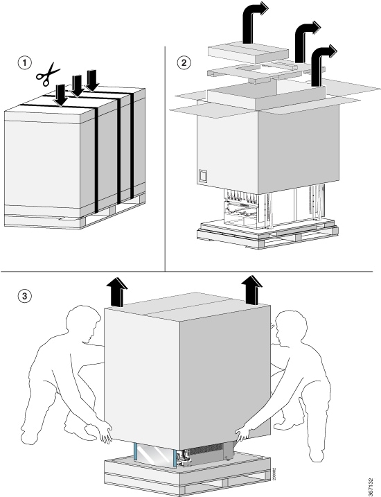
Unpack and Install the Chassis


Note


The images in this chapter are only for representation purposes, unless specified otherwise. The chassis' actual appearance and size may vary.

Unpack the Chassis


Tip


Ensure that you save the packaging in case you need to return any of the router components. For more information about returns, see Discrepancies or Damage?.

Ensure that there is sufficient room around the chassis pallet for unpacking. For information about the chassis dimensions and clearance requirements see, Clearance Requirements.

Carefully move the pallet containing the chassis to the staging area where you plan on unpacking it.
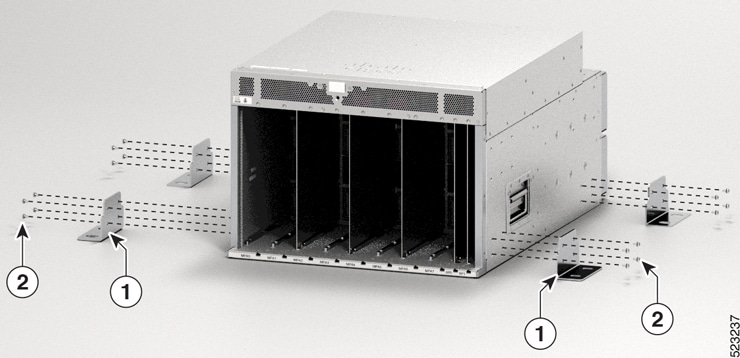
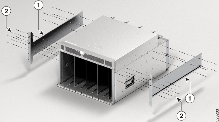
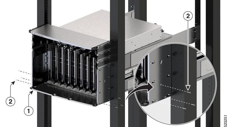
Figure 1. Move the Chassis Pallet to Staging Area
Figure 2. Remove Shipping Brackets from 8608 Chassis

1

Shipping brackets

2

M4 x 6-mm Phillips flat-head screws (16)

Remove the 16 x M4 screws from the 8608 chassis and remove the shipping brackets.

To make the chassis weigh less for moving, remove the following module and place them where their connectors will not be damaged:

  • Switch Cards

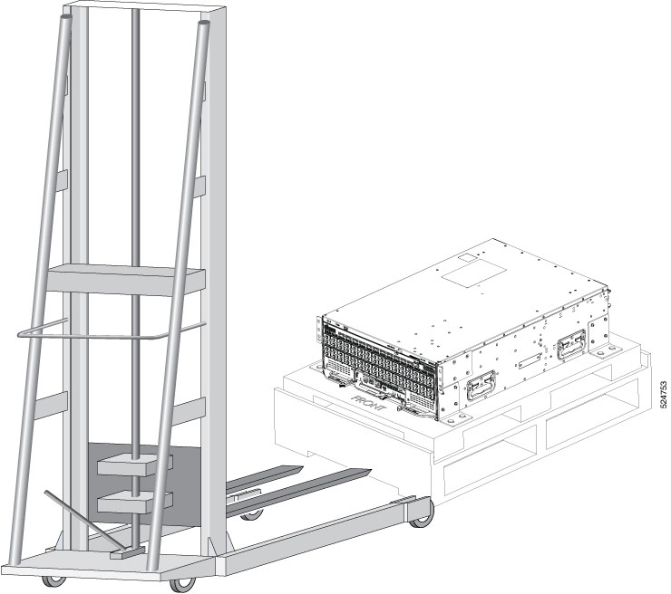
Leave the chassis on the pallet until you are ready to move and install the chassis in a rack.

What to do next:

Attach bottom support rails to the chassis

Install Bottom-Support Rails

The bottom-support rails support the weight of the router chassis in the rack. To maximize the stability of the rack, you must attach these rails at the lowest possible rack unit (RU).

Procedure


Step 1

Position the vertical rack rails at 32" depth to match with the length of the bottom-support rails. Check spacing considerations.

  • Maintain at least 16 RU (28 inches [71.12 cm]) for 8608 chassis of vertical space above support rails.

Step 2

Attach the bottom-support rail to the rack by using a Phillips torque screwdriver. Use the M6 x 19 mm or 12–24 x 3/4 inch screws for each end of the buttom-support rails and tighten each screw to 40 in-lbs (4.5 N-m) of torque.

Figure 3. Attach Bottom-Support Rails to Rack

1

Bottom-support rails

2

M4 x 6-mm Phillips flat-head screws (8)

Note

 
Use two screws on each end of each bottom-support rail.

Step 3

Repeat Steps 1 and 2 to attach the other bottom-support rail to the rack.

Note

 
Ensure that the two bottom-support rails are level with one another. If they are not level, adjust the higher rail down to the level of the lower rail.

What to do next

Transfer chassis to a mechanical lifting device.

Transfer Chassis to a Mechanical Lifting Device

Procedure


Step 1

Place the mechanical lifting device in front of the chassis on the pallet as shown.

Figure 4. Align the Lifting Device in Front of the Chassis on the Pallet

Step 2

Prepare to use the mechanical lifting device by placing a piece of cardboard on the surface of the lift (to prevent scratching).

Step 3

With at least two or three people move the chassis carefully with the pallet onto the lifting device as shown.

Figure 5. Move the Chassis on to the Lifting Device

What to do next

After moving the chassis to the room or area where you will install it, begin the procedure to mount the chassis into the rack.

Mount Chassis Into the Rack

This section describes how to install the router in a 4-post rack.

The following table lists the items that are contained in the rack-mount kit.

Table 1. Rack-Mount Kit (8608-RMBRKT)

Quantity

Part Description

8

Rack-mount brackets

20

M4 x 6-mm Phillips flat-head screws

1

Grounding lug and screws

To accommodate equipment racks with different mounting hole patterns, the chassis mounting brackets have groups of screw holes on either side. The mounting holes in the chassis mounting brackets are spaced so that one mounting hole in each hole group aligns with a corresponding hole in the equipment rack. By using the corresponding mounting hole (in the same hole group) on the opposite side of the chassis, you can level the chassis in the rack.


Note


To lift the chassis, use a mechanical lift. Do not use the handles on the side of the chassis. Use the side handles only for repositioning the chassis after it is already on the mechanical lift or in the rack or cabinet.

Warning


Statement 1032—Lifting the Chassis

To prevent personal injury or damage to the chassis, never attempt to lift or tilt the chassis using the handles on modules, such as power supplies, fans, or cards. These types of handles are not designed to support the weight of the unit.


Warning


Statement 1098—Lifting Requirement

people are required to lift the heavy parts of the product. To prevent injury, keep your back straight and lift with your legs, not your back.


Warning


Statement 1006—Chassis Warning for Rack-Mounting and Servicing

To prevent bodily injury when mounting or servicing this unit in a rack, you must take special precautions to ensure that the system remains stable. The following guidelines are provided to ensure your safety:

  • This unit should be mounted at the bottom of the rack if it is the only unit in the rack.

  • When mounting this unit in a partially filled rack, load the rack from the bottom to the top with the heaviest component at the bottom of the rack.

  • If the rack is provided with stabilizing devices, install the stabilizers before mounting or servicing the unit in the rack.


Note


Do not use the rack-mount brackets as slide rails. You must secure the rack-mount brackets only for removal and replacement of chassis.


Procedure


Step 1

Install the ear brackets to the sides of the chassis. Use the M4 x 6-mm Phillips flat-head screws to 26 in-lbs (2.93 N-m) of torque to fix the ear brackets to the chassis.

Figure 6. Install Ear Brackets to Sides of the Chassis

1

Ear brackets

2

M4 x 6-mm Phillips flat-head screws

Step 2

Using your mechanical lift, raise the chassis so that it is in level with or not more than 1/4 inch [0.635cm] above the rails.

Step 3

Push the chassis all the way onto the rack so that the vertical mounting brackets on the front of the chassis come in contact with the vertical mounting rails on the rack.

Step 4

Use screws provided with the rack to secure the chassis with the vertical mounting rails on the rack. Use 12 screws in the front side and 8 screws in the rear side to secure the chassis on to the rackmount.

Figure 7. Attach 8608 Chassis to Rack - Front view

1

Chassis

2

Bottom rails

3

M4 x 6-mm Phillips flat-head screws (10)

Step 5

Use the screws provided with the rack to attach the chassis rear rails. Install screws from outside the chassis to tighten each screw to 26 in-lbs (2.93 N-m) of torque. Four screws on each side of the chassis. Slide the rear brackets into the ear bracket that are attached to the chassis.

Figure 8. Attach 8608 Chassis to Rack - Rear View

1

Rear rack mounting brackets.

2

M4 x 6-mm Phillips flat-head screws (8)


What to do next

Connect the chassis to the ground at your facility.

Locate and Ground the Chassis


Warning


Statement 1024—Ground Conductor

This equipment must be grounded. To reduce the risk of electric shock, never defeat the ground conductor or operate the equipment in the absence of a suitably installed ground conductor. Contact the appropriate electrical inspection authority or an electrician if you are uncertain that suitable grounding is available.


Warning


Statement 1101—Connected To Grounded Outlet

In the Scandinavian countries (Denmark, Finland, Iceland, Norway, and Sweden) the appliance must be connected to a grounded outlet.


Procedure


Step 1

Locate the chassis grounding receptacles on your router chassis.

You can locate them at the following position:

  • At the left side panel, lower section towards the rear

Step 2

Use the wire stripper to strip one end of the 2-AWG wire approximately 0.75 inches (19.05 mm).

Step 3

Insert the 2-AWG wire into the wire receptacle on the grounding lug.

Figure 9. Chassis Ground Receptacles on Cisco 8608 Chassis

1

Locate ground

2

Align the lug holes and tighten the screws

Step 4

Use the crimping tool to carefully crimp the wire receptacle around the wire; this step is required to ensure a proper mechanical connection.

Step 5

Insert the two screws through the holes in the grounding lug. Ensure that the grounding lug does not interfere with other router hardware components.

Step 6

Use the Phillips screwdriver to carefully tighten the screws to 60 in-lbs 6.7 (N-m) of torque until the grounding lug is held firmly to the chassis. Do not overtighten the screws.

Step 7

Connect the opposite end of the grounding wire to the appropriate grounding point at your site to ensure an adequate chassis ground.


What to do next

Install cable management brackets.

Installing a Cable Management Bracket

To install a cable-management bracket, follow these steps:


Note


  • This procedure is applicable for Cisco 8608 chassis.

  • The cable management brackets for Cisco 8608 chassis supports only optics cables.


Before you begin

The chassis must be installed and secured to the rack.

Required tools and equipment:

  • Phillips screwdriver with a torque capability (customer supplied)

  • Cable management brackets (8608-CBLMGMT).


Note


  • The cable management brackets are shipped with the chassis.

  • The cable management bracket comes with a top hood.


Procedure


Step 1

Insert the alignment pins on top of the chassis.

Step 2

Position the top hood of the cable management assembly with its brackets pointing down.

Step 3

After you finish the alignment of the top hood with the chassis, secure it with counter sink screws and M4 x 18-mm screws.

Figure 10. Cable Management Brackets for 8608 Chassis

1

Top hood. The top hood and cable management brackets are one unit.

2

Counter sink screws

3

M4 x 18-mm Phillips flat-head screws

4

Alignment pins

5

Cable management brackets. The top hood and cable management brackets are one unit.


What to do next

Attach door kit to the chassis.

Attach Door Kit to Chassis

Before you begin

Before you can attach the front door to the chassis, you must attach the cable management brackets and bottom plate onto the chassis.

Required tools and equipment:

  • Phillips screwdriver with a torque capability (customer supplied)

  • Door kit (8608-DRKT)


    Note


    The door kit is optional.


Procedure


Step 1

After you've installed the cable management brackets onto the chassis, secure the left and right door brackets to the chassis vertical mounting brackets with flat-head Phillips screws M4 x 18-mm screws (use all screws provided in the kit). Insert one screw at the top and one at the bottom, likewise add more screws in this sequence. The number of screws may vary based on the chassis.

Figure 11. Secure Left and Right Door Brackets

Step 2

Position the bottom cover with its brackets pointing up, to the bottom of the two sides (right and left) of the door bracket screw holes.

Figure 12. Bottom Cover for 8608 Chassis

1

Bottom cover

2

M4 x 6 mm pan-head Phillips screws

Step 3

Secure the bottom cover to the door brackets by using four M4 x 6 mm pan-head Phillips screws. Tighten each screw to 11.5 to 15 in-lb (1.3 to 1.7 N·m) of torque.

Step 4

Tighten the door brackets screws to 11.5 to 15 in-lb (1.3 to 1.7Nm) of torque after completing the bottom cover installation.


Attach Front Door to Chassis

Procedure


Step 1

On the back side (open side) of one door, pull in on two protruding spring pins so that the pins are held inside the door frame.

Figure 13. Front Door Pins

1

Front door spring pins

Step 2

Align the spring pin to the hole in the bottom plate and release the spring pin, so that they insert into the bottom hole.

Step 3

Now align the spring pin to hole in the top hood and release the spring pin.

Step 4

Ensure the pins are properly inserted into the holes so that the door can freely swing on the spring pins.

Figure 14. Front Door Attached to 8608 Chassis

1

Front door

2

Top hood

Step 5

Repeat Steps 2–5 to install the other front door.

Figure 15. Doors Attached to the Chassis