Powering on the Router

This chapter describes how to connect the power modules in the chassis and to power on the router.

Power Supply Overview

Table 1. Feature History Table

Hardware

Release Information

Description

PSU4.3KW-HVPI Power Supply Unit for Cisco 8608 Router

Release 24.2.1

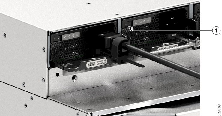
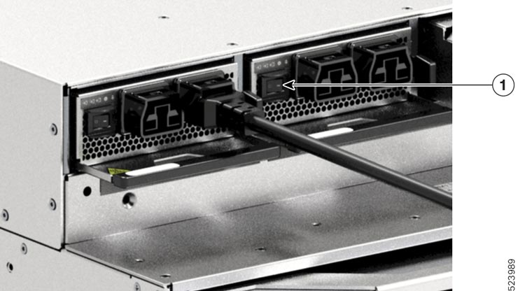
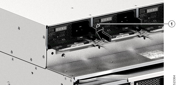
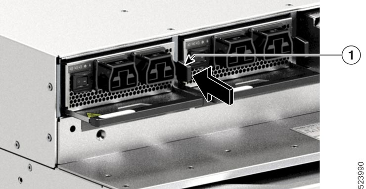
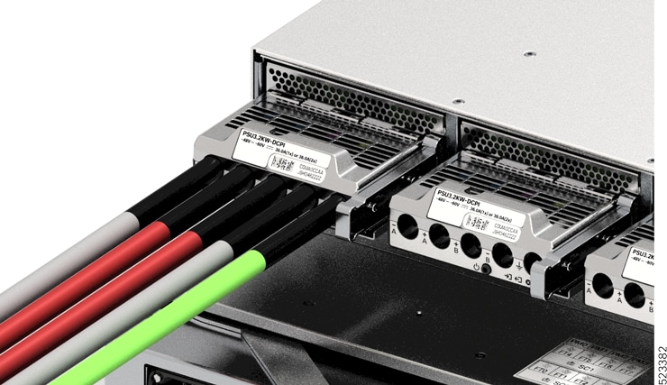
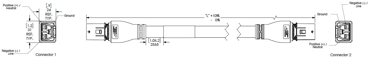
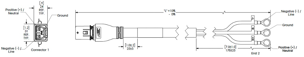
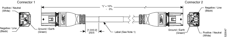
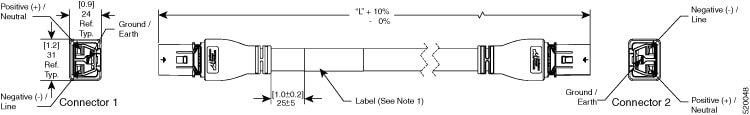
We're now introducing a high voltage power supply unit, PSU4.3KW-HVPI that accepts HVAC or HVDC input power to operate the Cisco 8608 router in the port side intake configuration. The PSU4.3KW-HVPI power supply unit has a dual input redundant power supply with 55V (main) and 3.3V (standby) outputs.

The benefits of the PSU4.3KW-HVPI power supply unit are:
  • Supports HVDC and HVAC input power

  • Helps when high power transceivers are installed in the router which need more power to operate

  • Provides better efficiency for power distribution

You can install up to four 3.2KW or 4.3KW HVAC/HVDC power supplies in the chassis. Ensure that all power connection wiring conforms to the rules and regulations in the National Electrical Code (NEC) and in local codes.


Note


  • The Cisco 8608 chassis doesn't support a mix of AC and DC Power Supply Units (PSUs).

  • The Cisco 8608 chassis doesn't support a mix of 3.2 KW and 4.3 KW PSUs.


Power Module Specifications

Power Module

Single/Dual Input

Nominal Input Voltage Range

Full Range

PSU3.2KW-ACPI

The AC power modules are single feed input with 3.2KW capacity at 220V. They also support operation at 110V with half the capacity of 1570W.

AC power modules are rated at 3.2KW maximum at 230V AC high line input, and 1570W maximum at 115V AC low line input.

100—120V AC

200—240V AC

85—300V AC

PSU3.2KW-DCPI

The DC power modules are dual feed input with 3.2KW capacity at any specified input voltage. DC power modules with single feed at any specified input voltage provide up to 1.6KW maximum capacity.

-48 to -60V DC

-40 to -75V DC

PSU4.3KW-HVPI

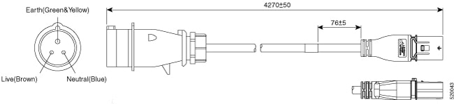
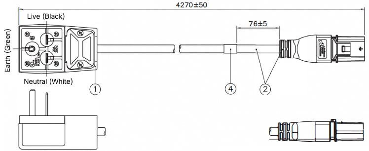
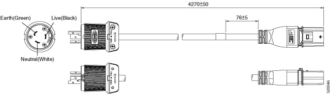
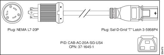
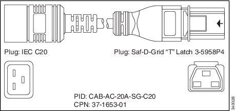
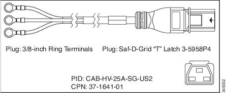
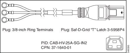
The AC power modules supply 4310W capacity with dual 220V feeds and 3200W capacity with a single 220V feed. The AC power modules supply 3130W capacity with dual 110V feeds and 1570W capacity with a single 110V feed.

The 4.3KW-HVPI PSUs shall operate within specification from 85V—305VAC or 192—400V DC continuously.

100—120V AC

200—240V AC

265—305V AC

192—219V DC

220—289V DC

290—400 V DC

85—305V AC

192—400V DC

Power Connection Guidelines for AC-Powered Systems

When connecting AC-input Power Supply Units (PSUs) to the site power source, observe the guidelines described here.


Warning


Statement 1028—More Than One Power Supply

This unit might have more than one power supply connection. To reduce risk of electric shock, remove all connections to de-energize the unit.


  • Ensure that the AC-input power supply module has a detachable power cord.

  • Each chassis power supply should have a separate, dedicated branch circuit.

    • North America

      • PSU3.2KW-ACPI only—Power supply modules require a 20 A circuit.

    • International—Circuits should be sized according to local and national codes.

  • If you are using a 208 or 240 VAC power source in North America, note that such lines are considered hot and the circuit must be protected by a two-pole circuit breaker.


    Warning


    Statement 1005—Circuit Breaker

    This product relies on the building’s installation for short-circuit (overcurrent) protection. To reduce risk of electric shock or fire, ensure that the protective device is rated not greater than: 20A.


    • 20 A circuit breaker for an AC-input power supply module.

    • 50 A DC-rated circuit breaker for each input of a DC-input power supply module, for safety purposes - irrespective of whether the inputs are power from a single or separate DC sources.


    Warning


    Statement 1022—Disconnect Device

    To reduce the risk of electric shock and fire, a readily accessible disconnect device must be incorporated in the fixed wiring.


  • The source AC outlet must be within 9.84 to 14 feet (3.0 to 4.293 meters) of the system - depending on the length of the power cord, and should be easily accessible.

  • The AC power receptacles used to plug in the chassis must be the grounding type. The grounding conductors that connect to the receptacles should connect to protective earth ground at the service equipment level.

Power Supply Unit Input and Output Ranges

Power Supply Restrictions and Considerations


Warning


Statement 1090—Installation by Skilled Person

Only a skilled person should be allowed to install, replace, or service this equipment. See statement 1089 for the definition of a skilled person.

There are no serviceable parts inside. To avoid risk of electric shock, do not open.


Warning


Statement 1091—Installation by an Instructed Person

Only an instructed person or skilled person should be allowed to install, replace, or service this equipment. See statement 1089 for the definition of an instructed or skilled person.

There are no serviceable parts inside. To avoid risk of electric shock, do not open.


Warning


Statement 1073—No User-Serviceable Parts

There are no serviceable parts inside. To avoid risk of electric shock, do not open.


Observe the following guidelines and limitations:

  • Use one type of power supply in a router.

  • The power supply type that is used in the router depends on the type and configuration of the transceivers installed in it.

  • Do not install a mix of AC and DC power supplies in a router.

  • The airflow direction must be the same for all power supply and fan modules in the router.

  • The AC-input power supplies support low-line voltage of 120V (Nominal) and high-line voltage of 220V (Nominal). If you need to change voltage type after installation, disconnect the feed from the power supply before switching the input voltage level.

This table summarizes the list of power supplies' input and output power ranges for different input applications:

Table 2. Input and Output Power Ranges at Low Line, High Line, Low Voltage, and High Voltage Applications

Power Supply Unit PIDs

Supported Routers

Input Voltage

Input Current (Max)

Output Power (Single/Dual Input)

PSU3.2KW-ACPI

For low line applications

Cisco 8608

100V AC – 115V AC

20A

1570W

PSU3.2KW-ACPI

For high line applications

Cisco 8608

180V AC – 300V AC

20A

3200W

PSU3.2KW-DCPI

For low line applications

Cisco 8608

-48V DC – -60V AC

55A

1600W

PSU3.2KW-DCPI

For high line applications

Cisco 8608

-40V DC – -75V AC

55A

3200W

PSU4.3KW-HVPI

For AC low line applications

Cisco 8608

100V AC – 115V AC

20A

1570W/3130W

PSU4.3KW-HVPI

For AC high line applications

Cisco 8608

180V AC – 305V AC

20A

3200W/4310W

PSU4.3KW-HVPI

For HVDC applications

Cisco 8608

192V DC - 400V DC

20A

3200W/4310W


Note


For more information on PSU specifications, see Power Module Specifications.


Connect AC Power to the Chassis


Warning


Statement 1017—Restricted Area

This unit is intended for installation in restricted access areas. Only skilled, instructed, or qualified personnel can access a restricted access area.


Warning


Statement 1005—Circuit Breaker

This product relies on the building’s installation for short-circuit (overcurrent) protection. To reduce risk of electric shock or fire, ensure that the protective device is rated not greater than: 20A.


AC: 20A, DC: 50A


Warning


Statement 1028—More Than One Power Supply

This unit might have more than one power supply connection. To reduce risk of electric shock, remove all connections to de-energize the unit.


Warning


Statement 1003—DC Power Disconnection

To reduce risk of electric shock or personal injury, disconnect DC power before removing or replacing components or performing upgrades.


Warning


Statement 1046—Installing or Replacing the Unit

To reduce risk of electric shock, when installing or replacing the unit, the ground connection must always be made first and disconnected last.

If your unit has modules, secure them with the provided screws.


Warning


Statement 1022—Disconnect Device

To reduce the risk of electric shock and fire, a readily accessible disconnect device must be incorporated in the fixed wiring.


Warning


Statement 1029—Blank Faceplates and Cover Panels

Blank faceplates and cover panels serve three important functions: they reduce the risk of electric shock and fire, they contain electromagnetic interference (EMI) that might disrupt other equipment, and they direct the flow of cooling air through the chassis. Do not operate the system unless all cards, faceplates, front covers, and rear covers are in place.


Caution


The chassis relies on the protective devices in the building installation to protect against short circuit, overcurrent, and ground faults. Ensure that the protective devices comply with local and national electrical codes.

Note


We recommend that you occupy all power supply slots of the router with power supplies. In case a power module fails, it is recommended to retain the failed power module in its slot until it is replaced with a new power module. This recommendation ensures that the system airflow is not impacted adversely, which may then result in the overheating of the router and its components.

Note


A dual pole breaker is needed for installation. For determining the recommended breaker size, please adhere to local and national rules and regulations. The breaker size is based on the specifications of the product for the current drawn and the specified voltage level.

Procedure


Step 1

Verify that the AC cable is installed in the correct AC source and outlet type.

Step 2

Set the AC-input power supply switch to the OFF (0) position.

Figure 1. Power Switch in Off Position - PSU3.2KW-ACPI

1

Power supply in the OFF (0) position

Figure 2. Power Switch in Off Position - PSU4.3KW-HVPI
Power Switch in Off Position - PSU4.3KW-HVPI

1

Power supply in the OFF (0) position

Step 3

Grasp the power supply handle with one hand and place your other hand underneath to support the bottom of the PSU. Slide the PSU all the way into the power supply bay. Ensure that the PSU is fully seated in the bay.

When correctly installed, the latch on the PSU locks-in the module, to avoid accidental removal of the module.

Figure 3. Slide the PSU into the Power Supply Bay - PSU3.2KW-ACPI
Slide the PSU into the Power Supply Bay

1

Power supply latch, which clicks into place

Figure 4. Slide the PSU into the Power Supply Bay - PSU4.3KW-HVPI

1

Power supply latch, which clicks into place

Step 4

Verify that all site power and grounding requirements have been met.

Step 5

Verify that you have the correct AC power cord for your location and power supply rating and only then plug the power cord connector into the power supply AC-in receptacle.

Figure 5. Plug Power Cord Connector into AC-in Receptacle - PSU3.2KW-ACPI
Plug Power Cord Connector into AC-in Receptacle - PSU3.2KW-ACPI

1

Power cord, plugged into the AC-in receptacle

Figure 6. Plug Power Cord Connector into AC-in Receptacle - PSU4.3KW-HVPI
Plug Power Cord Connector into AC-in Receptacle - PSU4.3KW-HVPI

1

Power cord, plugged into the AC-in receptacle

Step 6

Strap in the power cord retainer, to hold it in place and avoid accidental removal. For more information, see Power Cord Retainer Mechanism.

Step 7

Set the power switch to the On (|) position


Power Cord Retainer Mechanism

This section shows how to correctly operate the power cord retainer, to tighten or loosen it while installing or removing the power supply unit.


Note


Some of the illustrations do not include the power supply module, for the sake of clarity. The retainer is otherwise permanently fixed to the power supply module.


Figure 7. Parts of the Power Cord Retainer

1

The end that is fixed to the power supply unit

4

Flexible retainer strip

2

Clamp which can move towards the power supply or away from it

5

Retainer strip latch

3

Clamp latch

Installation and Removal Sequence

Installation—After you have inserted the power supply unit into the bay, first position the clamp closest to the power supply, near the plug round cylinder stress relief and then insert the flexible retainer strip into the clamp hole and tighten. The clamp cannot be moved after the flexible retainer strip is inserted into the clamp hole.

Removal—After you have turned off the power supply unit's rocker switch, first remove the flexible retainer strip from the clamp hole and then adjust the position of the clamp to remove the power cord.

Positioning the Clamp

In figure, Positioning the Clamp, the clamp can always move freely in direction 3a. To move the clamp in direction 3b, use a flathead screwdriver or similar device and push the clamp latch down. The figure, Clamp Latch - Detail, provides a clearer view of the clamp latch and the direction in which you have to push the latch to move it in direction 3b.

Figure 8. Positioning the Clamp

1

The end that is fixed to the power supply unit

3a and 3b

Directions in which the clamp can be moved, towards the power supply and away from it.

2

Clamp Latch

Figure 9. Clamp Latch - Detail

Inserting and Tightening the Retainer Strip

The flexible retainer strip inserts into the clamp hole and should be tightened around the power cord.

To loosen or remove the flexible retainer strip, position a flathead screwdriver or similar device between the flexible retainer strip and the retainer strip latch and push the latch away from the flexible retainer strip.
Figure 10. Flexible Retainer Strip

1

The end that is fixed to the power supply unit.

3

Flexible retainer strip

2

Direction in which to push the retainer strip latch, to loosen or remove the strip from the power cord (away from the retainer strip that is behind it)

Connect a DC Power Supply to the Chassis

When installing a DC-input Power Supply Unit (PSU), you will need access to the terminal block of the PSU in order to connect the DC-input wires. If the front panel of the chassis has limited access because of other interfering cables, consider connecting the DC-input wires to the terminal block, before you install the PSU in the chassis. If you do have clear access to the terminal block, you can install the PSU in the chassis first and then connect the DC-input wires.

The procedure to install the module in the chassis and the procedure to connect the DC-input wires have been described in Connecting the DC-Input Wires. You can complete either task first and then move on to the next, and finally power up the PSU.

Install a DC Power Supply Unit in the Chassis


Note


The power button has two modes of operation, which are described below. Press the power button for 10 seconds to toggle between modes; the LOCATE LED blinks for three seconds when you do.

  • Auto-on: When in this mode, the power supply module automatically starts or restarts on application or restoration of DC input power. This is the default mode.

    For NEBS compliance, the power button must be in the auto-on mode. When power is restored after a power failure, the power supply module recovers automatically.

  • Protected: When in this mode, if the DC power source output voltage is zero, or drops out for more than three seconds, you must press the power button for two seconds, to restore operation.


To install a DC-input Power Supply Unit (PSU) in the chassis, follow the steps described here.

Before you begin


Warning


Statement 1073—No User-Serviceable Parts

There are no serviceable parts inside. To avoid risk of electric shock, do not open.


Procedure


Step 1

Remove the new or replacement unit from its packaging.

Step 2

Grasp the module with one hand. With your other hand, push in the latch on the module.

Figure 11. Push the Latch on the Module
Push the Latch on the Module

1

Position of the nut on the side of the release latch before the latch is pushed in

2

Position of the nut on the side of the release latch after the latch is pushed in.

Step 3

Grasp the terminal block with one hand. Place your other hand underneath as you slide the PSU into the bay.

You will hear an audible click sound, which indicates that the module is locked into place, and connected with the backplane. Only the terminal block housing is not flush with the chassis.

If you do not push the release latch in before you slide the module into the bay, you will not hear the click sound, but this is an acceptable way of installing the module.

If the module is properly locked in place, you should not be able to remove the module without releasing the latch.

The following figure shows how a PSU slides into the bay:

Figure 12. PSU Slides into the Bay

The following figure shows a PSU that is fully installed in the bay:

Figure 13. PSU Installed in the Bay

Connecting the DC-Input Wires

When removing a DC Power Supply Unit (PSU), you will need access to the terminal block of the module to disconnect the DC-input wires. If the front panel of the chassis has limited access because of other interfering cables, consider removing the module from the chassis before disconnecting the DC-input wires. If you do have clear access to the terminal block, you can disconnect the DC-input wires and then remove the module from the chassis. In either case (whether you have access to the front panel or not), you must begin by completing all the steps described in Powering Down the DC-Input Power Supply. Proceed with the next task depending on your setup.

The procedures to disconnect DC-input wires and to remove the module from the chassis have been described in Disconnect the DC-Input Wires and Remove a DC Power Supply Unit from the Chassis.

To connect to the DC-input power source, follow the steps described here.

Before you begin


Warning


Statement 1073—No User-Serviceable Parts

There are no serviceable parts inside. To avoid risk of electric shock, do not open.


Procedure


Step 1

Locate the circuit breaker on the panel board that services the DC circuit, and switch the circuit breaker to the OFF position.

Step 2

Prepare the DC-input wires and the grounding wire. Crimp the lugs to the cable ends according to the lug manufacturer’s direction and your local electrical codes for installation.

Use a heat-shrink sleeve to ensure that there is no exposed wiring extending from the terminal block, when installed.

If you are using cables of different colors for your DC-input wires, we recommend one color for all the positive circuits, a second color for all the negative circuits, and a third color, which is normally solid green or green with yellow stripes, for the safety ground connection.

Step 3

Using a number one Phillips screwdriver, loosen the captive installation screw on the terminal block cover.

Step 4

Using a nut driver, loosen and remove the two nuts in the terminal slot meant for grounding, and set them aside.

The nut driver you are using must have at least a three-inch shaft, to clear the height of the terminal block cover and enable you to loosen or tighten the nuts in the terminal slots.

Warning


Statement 1046—Installing or Replacing the Unit

To reduce risk of electric shock, when installing or replacing the unit, the ground connection must always be made first and disconnected last.

If your unit has modules, secure them with the provided screws.

Figure 14. Remove the Nuts for Grounding
Remove the Nuts for Grounding

Step 5

Attach the lug to the two posts, secure with the two nuts, and tighten with the torque driver. The fastening torque is between 2.0 and 2.8 Nm. Do not overtorque.

Note


Always use a torque driver when you have to tighten nuts; it prevents you from overtightening them.

Figure 15. Tighten the Nuts
Tighten the Nuts

1

Lug secured with the two nuts

2

Grounding wire with heat-shrink sleeve

Step 6

Attach the four DC-input power source cables similarly.

When facing the terminal block, the circuits are in the following order from left to right: negative (- A), positive (+A), positive (+ B), and negative (-B).

-A and +A form one DC input, and + B and -B form another. Each DC input can be powered either from separate sources, or a suitable single source.

Figure 16. Attach DC-input Power Source Cables
Attach DC-input Power Source Cables

1

Lug secured with two nuts

5

DC-input wire for positive circuit (+ B)

2

Heat-shrink sleeve on all the wires

6

DC-input wire for positive circuit (+A)

3

Grounding wire

7

DC-input wire for negative circuit (- A)

4

DC-input wire for negative circuit (-B)

-

-

Step 7

Close the terminal block cover and finger-tighten the captive installation screw (approximately 0.25 Nm).

Figure 17. Close Terminal Block Cover
Close Terminal Block Cover

Power Up a DC Power Supply Unit

After you have installed the Power Supply Unit (PSU) in the chassis and connected the DC-input wires, follow the steps described here to power up the module and verify that the module is installed correctly.

Before you begin


Warning


Statement 1073—No User-Serviceable Parts

There are no serviceable parts inside. To avoid risk of electric shock, do not open.


Procedure


Step 1

For the powered down circuits connected to the PSUs, turn on the power at the circuit breaker.

The FAIL LED is illuminated for two to three seconds after DC input is applied through a circuit breaker.

Step 2

Check that the INPUT and OUTPUT LEDs on the PSU are green.

Note


DC-input PSUs are shipped with the power button in the default auto-on mode, which means that the unit automatically starts on application of DC-input power. When you install a new or replacement unit straight out of the box, you do not have to press the power button.

Step 3

Verify the polarity by measuring the voltage between the DC cable leads.

When measuring, check that the positive (+) lead and the negative (–) lead match the + and – labels on the DC-input PSU's terminal block.

If the DC inputs are powered from separate sources, also check that you have wired the cables straight across to their respective A source and B source, and respective negative and positive terminals. Crossed positive or negative cables constitute a severe safety hazard.


Power Supply Power Cord Specifications

3.2KW Power Supply Unit AC Power Cords

The following table lists the specifications for the AC power cords that are available for the 3.2KW AC-input power supply. The table also includes references to power cord illustrations.


Note


All 3.2KW power supply power cord:

  • Lengths range from 9.84 – 14 feet (3.0 – 4.293 meters); with most cord lengths between 13 and 14 feet (4.013 and 4.293 meters)

  • Have an IEC60320/C19 appliance connector at one end.

    Figure 18. IEC60320/C19 Appliance Connector

Table 3. 3200 W Power Supply AC Power Cords

Locale

Part Number

Cordset Rating

AC Source Plug Type

Argentina

CAB-I309-C19-INTL

20 A, 250 VAC

Figure 19. CAB-I309-C19-INTL= (Argentina)

Australia

CAB-AC-16A-AUS

16 A, 250 VAC

Figure 20. CAB-AC-16A-AUS= (Australia)

China

CAB-9K16A-CH

16 A, 250 VAC

Figure 21. CAB-9K16A-CH= (China)

Europe

CAB-CEE77-C19-EU

16 A, 250 VAC

Figure 22. CAB-CEE77-C19-EU= and CAB-I309-C19-INTL= (Europe)

CAB-I309-C19-INTL

20 A, 250 VAC

India

CAB-SABS-C19-IND

16 A, 250 VAC

Figure 23. CAB-SABS-C19-IND= (India)

International

CAB-I309-C19-INTL

20 A, 250 VAC

Figure 24. CAB-I309-C19-INTL= (International)

Israel

CAB-S132-C19-ISRL

16 A, 250 VAC

Figure 25. CAB-S132-C19-ISRL= (Israel)

Italy

CAB-C2316-C19-IT

16 A, 250 VAC

Figure 26. CAB-C2316-C19-IT= (Italy)

Japan, North America (Nonlocking Plug) 200 to 240 VAC Operation

CAB-US620P-C19-US

20 A, 250 VAC

Figure 27. CAB-US620P-C19-US= (Japan, North America - Nonlocking)

Japan, North America (Locking Plug) 200 to 240 VAC Operation

CAB-L620P-C19-US

20 A, 250 VAC

Figure 28. CAB-L620P-C19-US= ( Japan, North America - Locking )

North America

CAB-US520-C19-US

20 A, 125 VAC

Figure 29. CAB-US520-C19-US= (North America)

South Africa

CAB-I309-C19-INTL

20 A, 250 VAC

Figure 30. CAB-I309-C19-INTL= (South Africa)

UPS 220V

CAB-C19-CBN

20 A, 250 VAC

Figure 31. 130923

4.3KW Power Supply Power Cord Specifications


Note


Always use the Saf-D-Grid connector toward the router.
Table 4. 30A HVAC/HVDC Cables for PSU4.3KW-HVPI PSU

Locale

Part Number

Cisco Part Number (CPN)

Power Cord Set Rating

Connector Part Number

Power Cord Illustration

AUSTRALIA/NEW ZEALAND

CAB-AC-32A-ANZ

37-101007-01

32A, 250VAC

Saf-D-Grid 3-5958P4 to Hubbell C332P6S Plug

Refer the figure in 30A HVAC/HVDC Cable Illustrations

SWITZERLAND

CAB-AC-32A-CHE

37-101007-01

32A, 250VAC

Saf-D-Grid 3-5958P4 to Hubbell C332P6S Plug

Refer the figure in 30A HVAC/HVDC Cable Illustrations

ITALY

CAB-AC-32A-ITA

37-101007-01

32A, 250VAC

Saf-D-Grid 3-5958P4 to Hubbell C332P6S Plug

Refer the figure in 30A HVAC/HVDC Cable Illustrations

SOUTH AFRICA

CAB-AC-32A-ZAF

37-101007-01

32A, 250VAC

Saf-D-Grid 3-5958P4 to Hubbell C332P6S Plug

Refer the figure in 30A HVAC/HVDC Cable Illustrations

BRAZIL

CAB-AC-32A-BRZ

37-101007-01

32A, 250VAC

Saf-D-Grid 3-5958P4 to Hubbell C332P6S Plug

Refer the figure in 30A HVAC/HVDC Cable Illustrations

ISRAEL

CAB-AC-32A-ISR

37-101007-01

32A, 250VAC

Saf-D-Grid 3-5958P4 to Hubbell C332P6S Plug

Refer the figure in 30A HVAC/HVDC Cable Illustrations

ARGENTINA

CAB-AC-32A-ARG

37-101007-01

32A, 250VAC

Saf-D-Grid 3-5958P4 to Hubbell C332P6S Plug

Refer the figure in 30A HVAC/HVDC Cable Illustrations

INDIA

CAB-AC-32A-IND

37-101007-01

32A, 250VAC

Saf-D-Grid 3-5958P4 to Hubbell C332P6S Plug

Refer the figure in 30A HVAC/HVDC Cable Illustrations

NORTH AMERICA

CAB-AC-30A-US1

37-101008-01

30A, 250VAC

Saf-D-Grid 3-5958P4 to VOLEX 174606

Refer the figure in 30A HVAC/HVDC Cable Illustrations

NORTH AMERICA

CAB-AC-30A-US2

37-101009-01

30A, 250VAC

Saf-D-Grid 3-5958P4 to VOLEX 174606

Refer the figure in 30A HVAC/HVDC Cable Illustrations

NORTH AMERICA

CAB-DC-30A-US1

37-101014-01

30A, 400VDC

Saf-D-Grid 3-5958P4 to Saf-D-Grid 3-5958P4

Refer the figure in 30A HVAC/HVDC Cable Illustrations

NORTH AMERICA

CAB-DC-30A-US2

37-101016-01

30A, 400VDC

Saf-D-Grid 3-5958P4 to Saf-D-Grid 3-5958P4

Refer the figure in 30A HVAC/HVDC Cable Illustrations

NORTH AMERICA

CAB-AC-30A-US3

37-101013-01

30A, 277VAC

Saf-D-Grid 3-5958P4 to HBL2631

Refer the figure in 30A HVAC/HVDC Cable Illustrations

NORTH AMERICA

CAB-AC-30A-US4

37-101018-01

30A, 300VAC

Saf-D-Grid 3-5958P4 to Saf-D-Grid 3-6074P30

Refer the figure in 30A HVAC/HVDC Cable Illustrations

IEC/EU

CAB-AC-32A-EU

37-101019-01

32A, 300VAC

Saf-D-Grid 3-5958P4 to Saf-D-Grid 3-6074P30

Refer the figure in 30A HVAC/HVDC Cable Illustrations

IEC/EU

CAB-DC-32A-EU1

37-101015-01

32A, 400VDC

Saf-D-Grid 3-5958P4 to Saf-D-Grid 3-5958P4

Refer the figure in 30A HVAC/HVDC Cable Illustrations

IEC/EU

CAB-DC-32A-EU2

37-101017-01

32A, 400VDC

Saf-D-Grid 3-5958P4 to Saf-D-Grid 3-5958P4

Refer the figure in 30A HVAC/HVDC Cable Illustrations

CHINA

CAB-AC-32A-CHN

37-101010-01

32A, 250VAC

-

Refer the figure in 30A HVAC/HVDC Cable Illustrations

KOREA

CAB-AC-32A-KOR

37-101012-01

32A, 250VAC

-

Refer the figure in 30A HVAC/HVDC Cable Illustrations

30A HVAC/HVDC Cable Illustrations

Figure 32. CAB-AC-32A-ANZ, CAB-AC-32A-CHE, CAB-AC-32A-ITA, CAB-AC-32A-BRZ, CAB-AC-32A-ZAF, CAB-AC-32A-ISR, CAB-AC-32A-IND, CAB-AC-32A-ARG Power Cord and Plugs for Standard AC Power Supply
Figure 33. CAB-AC-30A-US1 Power Cord and Plugs for Standard AC Power Supply
Figure 34. CAB-AC-30A-US2 Power Cord and Plugs for Standard AC Power Supply
Figure 35. CAB-DC-30A-US1 Power Cord and Plugs for HVDC Power Supply
Figure 36. CAB-DC-30A-US2 Power Cord and Plugs for HVDC Power Supply
Figure 37. CAB-AC-30A-US3 Power Cord and Plugs for Standard AC Power Supply
Figure 38. CAB-AC-30A-US4 Power Cord and Plugs for Standard AC Power Supply
Figure 39. CAB-AC-32A-EU Power Cord and Plugs for Standard AC Power Supply
Figure 40. CAB-DC-32A-EU1 Power Cord and Plugs for HVDC Power Supply
Figure 41. CAB-DC-32A-EU2 Power Cord and Plugs for HVDC Power Supply
Figure 42. CAB-AC-32A-CHN Power Cord and Plugs for Standard AC Power Supply
Figure 43. CAB-AC-32A-KOR Power Cord and Plugs for Standard AC Power Supply
Table 5. 20A HVAC/HVDC Cables for PSU4.3KW-HVPI PSU
Locale Part Number Cisco Part Number (CPN) Length Power Cord Rating Connectors

Power Cord Illustration

Argentina CAB-AC-16A-SG-AR 37-1649-01 14 ft (4.26 m) 16A, 250 VAC

Refer the figure in 20A HVAC/HVDC Cables for PSU6.3KW-20A-HV

Australia CAB-AC-16A-SG-AZ 37-1661-01 14 ft (4.26 m) 16A, 250 VAC

Refer the figure in 20A HVAC/HVDC Cables for PSU6.3KW-20A-HV

Brazil CAB-AC-16A-SG-BR 37-1650-01 14 ft (4.26 m) 16A, 250 VAC

Refer the figure in 20A HVAC/HVDC Cables for PSU6.3KW-20A-HV

China CAB-AC-16A-SG-CH 37-1655-01 14 ft (4.26 m) 16A, 250 VAC

Refer the figure in 20A HVAC/HVDC Cables for PSU6.3KW-20A-HV

China CAB-AC-16A-CN 37-1655-01 14 ft (4.26 m) 16A, 250 VAC

Refer the figure in 20A HVAC/HVDC Cables for PSU6.3KW-20A-HV

Europe CAB-AC-16A-SG-EU 37-1660-01 14 ft (4.26 m) 16A, 250 VAC

Refer the figure in 20A HVAC/HVDC Cables for PSU6.3KW-20A-HV

India CAB-AC-16A-SG-IND 37-1863-01 14 ft (4.26 m) 16A, 250 VAC

Refer the figure in 20A HVAC/HVDC Cables for PSU6.3KW-20A-HV

International/UK CAB-AC-16A-SG-IN 37-1659-01 14 ft (4.26 m) 16A, 250 VAC

Refer the figure in 20A HVAC/HVDC Cables for PSU6.3KW-20A-HV

Israel CAB-AC-16A-SG-IS 37-1658-01 14 ft (4.26 m) 16A, 250 VAC

Refer the figure in 20A HVAC/HVDC Cables for PSU6.3KW-20A-HV

Italy CAB-AC-16A-SG-IT 37-1651-01 14 ft (4.26 m) 16A, 250 VAC

Refer the figure in 20A HVAC/HVDC Cables for PSU6.3KW-20A-HV

Japan CAB-AC-16A-SG-JPN 37-1656-01 14 ft (4.26 m) 16A, 250 VAC

Refer the figure in 20A HVAC/HVDC Cables for PSU6.3KW-20A-HV

South Africa CAB-AC-16A-SG-SA 37-1647-01 14 ft (4.26 m) 16A, 250 VAC

Refer the figure in 20A HVAC/HVDC Cables for PSU6.3KW-20A-HV

Switzerland CAB-AC-16A-SG-SW 37-1654-01 14 ft (4.26 m) 16A, 250 VAC

Refer the figure in 20A HVAC/HVDC Cables for PSU6.3KW-20A-HV

South Korea CAB-AC-16A-SG-SK 37-1646-01 14 ft (4.26 m) 16A, 250 VAC

Refer the figure in 20A HVAC/HVDC Cables for PSU6.3KW-20A-HV

UK CAB-AC-16A-SG-UK 37-1864-01 14 ft (4.26 m) 16A, 250 VAC

Refer the figure in 20A HVAC/HVDC Cables for PSU6.3KW-20A-HV

North America (locking) 200-240 VAC operation CAB-AC-20A-SG-US3 37-1656-01 14 ft (4.26 m) 20A, 250 VAC Saf-D-Grid to L6-20

Refer the figure in 20A HVAC/HVDC Cables for PSU6.3KW-20A-HV

North America 277 VAC operation CAB-AC-20A-SG-US4 37-1645-01 14 ft (4.26 m) 20A, 277 VAC Saf-D-Grid to L7-20

Refer the figure in 20A HVAC/HVDC Cables for PSU6.3KW-20A-HV

North America Cabinet Jumper Power Distribution unit (PDU) CAB-AC-20A-SG-C20 37-1653-01 14 ft (4.26 m) 20A, 250 VAC Saf-D-Grid to C20

Refer the figure in 20A HVAC/HVDC Cables for PSU6.3KW-20A-HV

North America, Ring Terminal source plug CAB-HV-25A-SG-US2 37-1641-01 14 ft (4.26 m) 20A, 300 VAC/500 VDC Saf-D-Grid to 3 ring terminal

Refer the figure in 20A HVAC/HVDC Cables for PSU6.3KW-20A-HV

International IEC/EU, Ring Terminal source plug CAB-HV-25A-SG-IN2 37-1640-01 14 ft (4.26 m) 20A, 300 VAC/500 VDC Saf-D-Grid to 3 ring terminal

Refer the figure in 20A HVAC/HVDC Cables for PSU6.3KW-20A-HV

US, IEC/EU, CANADA, MEXICO, BRAZIL, NETHERLANDS, IRELAND, FRANCE, UK, GERMANY, SWITZERLAND, NORWAY, SPAIN, ITALY, SINGAPORE, CHINA CAB-AC-20A-NA 37-2126-01 6.6 ft (2m) 20A, 250VAC Saf-D-Grid 3-5958P2 to IEC 60320 C20

Refer the figure in 20A HVAC/HVDC Cables for PSU6.3KW-20A-HV

20A HVAC/HVDC Cable Illustrations
Figure 44. CAB-AC-16A-SG-AR Power Cord
Figure 45. CAB-AC-16A-SG-AZ Power Cord
Figure 46. CAB-AC-16A-SG-BR Power Cord
Figure 47. CAB-AC-16A-SG-CH Power Cord
Figure 48. CAB-AC-16A-SG-EU Power Cord
Figure 49. CAB-AC-16A-SG-IND Power Cord
Figure 50. CAB-AC-16A-SG-IN Power Cord
Figure 51. CAB-AC-16A-SG-IS Power Cord
Figure 52. CAB-AC-16A-SG-IT Power Cord
Figure 53. CAB-AC-16A-SG-JPN Power Cord
Figure 54. CAB-AC-16A-SG-SA Power Cord
Figure 55. CAB-AC-16A-SG-SW Power Cord
Figure 56. CAB-AC-16A-SG-UK Power Cord
Figure 57. CAB-AC-20A-SG-US Power Cord
Figure 58. CAB-AC-20A-SG-US1 Power Cord
Figure 59. CAB-AC-20A-SG-US2 Power Cord
Figure 60. CAB-AC-20A-SG-US3 Power Cord
Figure 61. CAB-AC-20A-SG-US4 Power Cord
Figure 62. CAB-AC-20A-SG-C20 Power Cord
Figure 63. CAB-HV-25A-SG-US2 Power Cord
Figure 64. CAB-HV-25A-SG-IN2 Power Cord
Figure 65. CAB-HV-25A-SG-IN3 Power Cord
Figure 66. CAB-AC-20A-NA Power Cord