Connect Router to the Network


Note


The images in this chapter are only for representation purposes, unless specified otherwise. The chassis' actual appearance and size may vary.

Connecting a Console to the Router

Before you create a network management connection for the router or connect the router to the network, you must create a local management connection through a console terminal and configure an IP address for the router. The router can be accessed using remote management protocols, such as SSH and Telnet. By default, SSH is included in the software image. But telnet is not part of the software image. You must manually install the telnet optional package to use it.

You also can use the console to perform the following functions, each of which can be performed through the management interface after you make that connection:

  • configure the router using the command-line interface (CLI)

  • monitor network statistics and errors

  • configure Simple Network Management Protocol (SNMP) agent parameters

  • initiate software download updates via console

You make this local management connection between the asynchronous serial port on a Route Processor card and a console device capable of asynchronous transmission. Typically, you can use a computer terminal as the console device. On the Route Processor cards, you use the console serial port.


Note


Before you can connect the console port to a computer terminal, ensure that the computer terminal supports VT100 terminal emulation. The terminal emulation software makes communication between the router and computer possible during setup and configuration.

Before you begin

  • The router must be fully installed in its rack. The router must be connected to a power source and grounded.

  • The necessary cabling for the console, management, and network connections must be available.

    • An RJ45 rollover cable and a DB9F/RJ45 adapter.

    • Network cabling should already be routed to the location of the installed router.

Procedure


Step 1

Configure the console device to match the following default port characteristics:

  • 115200 baud

  • 8 data bits

  • 1 stop bit

  • No parity

Step 2

Connect and RJ45 rollover cable to a terminal, PC terminal emulator, or terminal server.

The RJ45 rollover cable is not part of the accessory kit.

Step 3

Route the RJ45 rollover cable as appropriate and connect the cable to the console port on the chassis.

If the console or modem cannot use an RJ45 connection, use the DB9F/RJ45F PC terminal adapter. Alternatively, you can use an RJ45/DSUB F/F or RJ45/DSUB R/P adapter, but you must provide those adapters.


What to do next

You are ready to create the initial router configuration.

Connect the Management Interface

The Route Processor management port (MGMT ETH) provides out-of-band management, which lets you to use the command-line interface (CLI) to manage the router by its IP address. This port uses a 10/100/1000 Ethernet connection with an RJ-45 interface.


Note


In a dual Route Processor router, you can ensure that the active Route Processor card is always connected to the network by connecting the management interface on both Route Processor cards to the network. That is, you can perform this task for each Route Processor card. When the Route Processor card is active, the router automatically has a management interface that is running and accessible from the network.

Caution


To prevent an IP address conflict, do not connect the MGMT 100/1000 Ethernet port until the initial configuration is complete.

Before you begin

You must have completed the initial router configuration.

Procedure


Step 1

Connect a modular, RJ-45, UTP cable to the MGMT ETH port on the Route Processor card.

Step 2

Route the cable through the central slot in the cable management system.

Step 3

Connect the other end of the cable to a 100/1000 Ethernet port on a network device.


What to do next

You are ready to connect the interface ports to the network.

Transceivers, Connectors, and Cables

RJ-45 Connectors

The RJ-45 connector connects Category 3, Category 5, Category 5e, Category 6, or Category 6A foil twisted-pair or unshielded twisted-pair cable from the external network to the following module interface connectors:

  • Router chassis

    • CONSOLE port

    • MGMT ETH port


Caution


To comply with GR-1089 intrabuilding, lightning immunity requirements, you must use a foil twisted-pair (FTP) cable that is properly grounded at both ends.


The following figure shows the RJ-45 connector.

Figure 1. RJ-45 Connector

1

Pin 1

2

Pin 8

Install and Remove SFP or SFP+ Modules

Before you remove or install an SFP or SFP+ module, read the installation information in this section.


Warning


Statement 1051—Laser Radiation

Invisible laser radiation may be emitted from disconnected fibers or connectors. Do not stare into beams or view directly with optical instruments.


Caution


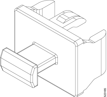
Protect the line card by inserting a clean SFP/SFP+ module cage cover, which is shown in the figure below, into the optical module cage when there is no SFP or SFP+ module installed.
Figure 2. SFP/SFP+ Module Cage Cover

Caution


Protect the SFP or SFP+ modules by inserting clean dust covers into them after the cables are removed. Be sure to clean the optic surfaces of the fiber cables before you plug them back into the optical ports of another module. Avoid getting dust and other contaminants into the optical ports of your SFP or SFP+ modules, because the optics do not work correctly when obstructed by dust.

Caution


We strongly recommended that you do not install or remove the SFP or SFP+ module with fiber-optic cables that are attached to it because of the potential of damaging the cable, the cable connector, or the optical interfaces in the module. Disconnect all cables before removing or installing an SFP or SFP+ module. Removing and inserting a module can shorten its useful life, so you should not remove and insert modules any more than is absolutely necessary.

Note


When installing an SFP or SFP+ module, you should hear a click as the triangular pin on the bottom of the module snaps into the hole in the receptacle. The click indicates that the module is correctly seated and secured in the receptacle. Verify that the modules are seated and secured in their assigned receptacles on the line card by firmly pushing on each SFP or SFP+ module.

Bale Clasp SFP or SFP+ Module

The bale clasp SFP or SFP+ module has a clasp that you use to remove or install the module (see the figure below).

Figure 3. Bale Clasp SFP or SFP+ Module

Installing the Transceiver Module


Warning


Statement 1055—Class 1/1M Laser

Invisible laser radiation is present. Do not expose to users of telescopic optics. This applies to Class 1/1M laser products.


Warning


Statement 1051—Laser Radiation

Invisible laser radiation may be emitted from disconnected fibers or connectors. Do not stare into beams or view directly with optical instruments.


Warning


Statement 1079—Hot Surface

This icon is a hot surface warning. To avoid personal injury, do not touch without proper protection.


Caution


The transceiver module is a static-sensitive device. Always use an ESD wrist strap or similar individual grounding device when handling transceiver modules or coming into contact with system modules.

Caution


Protect the transceiver ports by inserting clean dust caps (8000-QSFP-DCAP) into any ports not in use. Be sure to clean the optic surfaces of the fiber cables before you plug them back into the optical ports of another module. Use dust caps for all the open ports on the chassis.

The router ships with dust caps plugged in. We highly recommend you to keep the dust caps plugged in until you are ready to plug an optic.

The dust caps protect the ports from possible EMI interference and also avoid contamination due to dust collection. To meet the EMI interference requirements, you must use the metal dust caps when the ports are not in use by optical modules.


The following table provides the supported port details and operating temperature of the QDD-400G-ZR-S and DP04QSDD-HE0 optical modules when port side exhaust or port side intake fans and power supplies are used.

Table 1. Supported Ports and Operating Temperature of QDD-400G-ZR-S and DP04QSDD-HE0 Optical Modules
Fixed-Port Routers Port Side Intake Fans and Power Supplies Port Side Intake Operating Temperature

Cisco 8608

DP04QSDD-HE0 – supported on all 400G ports

40° C at sea level or 35° C at 1500 meter

Cisco 8508

  • QDD-400G-ZR-S – supported on all 400G ports

40° C at sea level or 35° C at 1500 meter

The QSFP transceiver module has a pull-tab latch. To install a transceiver module, follow these steps:

Procedure


Step 1

Attach an ESD wrist strap to yourself and a properly grounded point on the chassis or the rack.

Step 2

Remove the transceiver module from its protective packaging.

Step 3

Check the label on the transceiver module body to verify that you have the correct model for your network. Do not remove the dust plug until you’re ready to attach the network interface cable. Dust plug is not shown in the images.

Step 4

Hold the transceiver by the pull-tab so that the identifier label is on the top.

Step 5

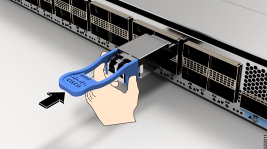
Align the transceiver module in front of the module’s transceiver socket opening and carefully slide the transceiver into the socket until the transceiver contact with the socket electrical connector.

Figure 4. Installing the QSFP Transceiver Module

Step 6

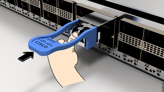
Press firmly on the front of the transceiver module with your thumb to fully seat the transceiver in the module’s transceiver socket (see the below figure).

Caution

 
If the latch isn’t fully engaged, you might accidentally disconnect the transceiver module.
Figure 5. Seating the QSFP Transceiver Module

Remove a Bale Clasp SFP or SFP+ Module

To remove this type of SFP or SFP+ module, follow these steps:

Procedure


Step 1

Attach an ESD-preventive wrist or ankle strap and follow its instructions for use.

Step 2

Disconnect and remove all interface cables from the ports; note the current connections of the cables to the ports on the line card.

Step 3

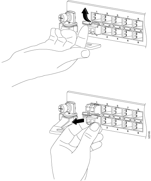
Open the bale clasp on the SFP module with your index finger, as shown in the figure below. If the bale clasp is obstructed and you cannot use your index finger to open it, use a small flat-blade screwdriver or other long, narrow instrument to open the bale clasp.

Step 4

Grasp the SFP module between your thumb and index finger and carefully remove it from the port, as shown in the figure below.

Note

 
This action must be performed during your first instance. After all the ports are populated, this may not be possible.
Figure 6. Removing a Bale Clasp SFP or SFP+ Module

Step 5

Place the removed SFP module on an antistatic mat, or immediately place it in a static shielding bag if you plan to return it to the factory.

Step 6

Protect your line card by inserting a clean SFP module cage covers into the optical module cage when there is no SFP module installed.


Install and Remove QSFP Transceiver Modules

This section provides the installation, cabling, and removal instructions for the Quad Small Form-Factor Pluggable transceiver modules. Refer to the Cisco Optical Transceiver Handling Guide for additional details on optical transceivers.

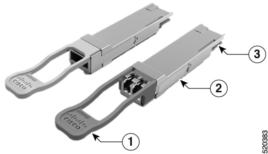
The following figure shows a 400-Gigabit QSFP-DD optical transceiver.

Figure 7. 400-Gigabit QSFP-DD Transceiver Module

1

Pull-tab

2

QSFP-DD transceiver body

3

Electrical connection to the module circuitry


Warning


Statement 1079—Hot Surface

This icon is a hot surface warning. To avoid personal injury, do not touch without proper protection.


Required Tools and Equipment

You need these tools to install the transceiver modules:

  • Wrist strap or other personal grounding device to prevent ESD occurrences.

  • Antistatic mat or antistatic foam to set the transceiver on.

  • Fiber-optic end-face cleaning tools and inspection equipment.

Installing the Transceiver Module


Warning


Statement 1055—Class 1/1M Laser

Invisible laser radiation is present. Do not expose to users of telescopic optics. This applies to Class 1/1M laser products.


Warning


Statement 1051—Laser Radiation

Invisible laser radiation may be emitted from disconnected fibers or connectors. Do not stare into beams or view directly with optical instruments.


Warning


Statement 1079—Hot Surface

This icon is a hot surface warning. To avoid personal injury, do not touch without proper protection.


Caution


The transceiver module is a static-sensitive device. Always use an ESD wrist strap or similar individual grounding device when handling transceiver modules or coming into contact with system modules.

Caution


Protect the transceiver ports by inserting clean dust caps (8000-QSFP-DCAP) into any ports not in use. Be sure to clean the optic surfaces of the fiber cables before you plug them back into the optical ports of another module. Use dust caps for all the open ports on the chassis.

The router ships with dust caps plugged in. We highly recommend you to keep the dust caps plugged in until you are ready to plug an optic.

The dust caps protect the ports from possible EMI interference and also avoid contamination due to dust collection. To meet the EMI interference requirements, you must use the metal dust caps when the ports are not in use by optical modules.


The following table provides the supported port details and operating temperature of the QDD-400G-ZR-S and DP04QSDD-HE0 optical modules when port side exhaust or port side intake fans and power supplies are used.

Table 2. Supported Ports and Operating Temperature of QDD-400G-ZR-S and DP04QSDD-HE0 Optical Modules
Fixed-Port Routers Port Side Intake Fans and Power Supplies Port Side Intake Operating Temperature

Cisco 8608

DP04QSDD-HE0 – supported on all 400G ports

40° C at sea level or 35° C at 1500 meter

Cisco 8508

  • QDD-400G-ZR-S – supported on all 400G ports

40° C at sea level or 35° C at 1500 meter

The QSFP transceiver module has a pull-tab latch. To install a transceiver module, follow these steps:

Procedure


Step 1

Attach an ESD wrist strap to yourself and a properly grounded point on the chassis or the rack.

Step 2

Remove the transceiver module from its protective packaging.

Step 3

Check the label on the transceiver module body to verify that you have the correct model for your network. Do not remove the dust plug until you’re ready to attach the network interface cable. Dust plug is not shown in the images.

Step 4

Hold the transceiver by the pull-tab so that the identifier label is on the top.

Step 5

Align the transceiver module in front of the module’s transceiver socket opening and carefully slide the transceiver into the socket until the transceiver contact with the socket electrical connector.

Figure 8. Installing the QSFP Transceiver Module

Step 6

Press firmly on the front of the transceiver module with your thumb to fully seat the transceiver in the module’s transceiver socket (see the below figure).

Caution

 
If the latch isn’t fully engaged, you might accidentally disconnect the transceiver module.
Figure 9. Seating the QSFP Transceiver Module

Attach the Optical Network Cable

Before you begin

Before you remove the dust plugs and make any optical connections, follow these guidelines:

  • Keep the protective dust plugs installed in the unplugged fiber-optic cable connectors and in the transceiver optical bores until you are ready to make a connection.

  • Inspect and clean the optical connector end faces just before you make any connections.

  • Grasp the optical connector only by the housing to plug or unplug a fiber-optic cable.


Note


The transceiver modules and fiber connectors are keyed to prevent incorrect insertion.

Note


The multiple-fiber push-on (MPO) connectors on the optical transceivers support network interface cables with either physical contact (PC) or ultra-physical contact (UPC) flat polished face types. The MPO connectors on the optical transceivers do not support network interface cables with an angle-polished contact (APC) face type.

Note


Inspect the MPO connector for the correct cable type, cleanliness, and any damage. For complete information on inspecting and cleaning fiber-optic connections, see the Inspection and Cleaning Procedures for Fiber-Optic Connections document.


Procedure


Step 1

Remove the dust plugs from the optical network interface cable MPO connectors and from the transceiver module optical bores. Save the dust plugs for future use.

Step 2

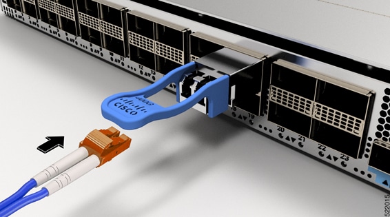
Attach the network interface cable MPO connectors immediately to the transceiver module.

Figure 10. Cabling a Transceiver Module

Removing the Transceiver Module


Warning


Statement 1055—Class 1/1M Laser

Invisible laser radiation is present. Do not expose to users of telescopic optics. This applies to Class 1/1M laser products.


Warning


Statement 1051—Laser Radiation

Invisible laser radiation may be emitted from disconnected fibers or connectors. Do not stare into beams or view directly with optical instruments.


Warning


Statement 1079—Hot Surface

This icon is a hot surface warning. To avoid personal injury, do not touch without proper protection.


Caution


The transceiver module is a static-sensitive device. Always use an ESD wrist strap or similar individual grounding device when handling transceiver modules or coming into contact with modules.

Caution


Protect the transceiver ports by inserting clean dust caps (8000-QSFP-DCAP) into any ports not in use. Be sure to clean the optic surfaces of the fiber cables before you plug them back into the optical ports of another module. Use dust caps for all the open ports on the chassis.

The router ships with dust caps plugged in. We highly recommend you to keep the dust caps plugged in until you are ready to plug an optic.

The dust caps protect the ports from possible EMI interference and also avoid contamination due to dust collection. To meet the EMI interference requirements, you must use the metal dust caps when the ports are not in use by optical modules.


To remove a transceiver module, follow these steps:

Procedure


Step 1

Disconnect the network interface cable from the transceiver connector.

Step 2

Install the dust plug immediately into the transceiver’s optical bore.

Step 3

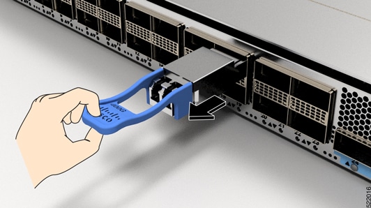
Grasp the pull-tab and gently pull to release the transceiver from the socket.

Figure 11. Removing the QSFP Transceiver Module

Step 4

Slide the transceiver out of the socket.

Step 5

Place the transceiver module into an antistatic bag.


Connect Interface Ports

You can connect optical interface ports on line cards with other devices for network connectivity.

Disconnect Optical Ports from the Network

When you need to remove fiber-optic transceivers, you must first remove the fiber-optic cables from the transceiver before you remove the transceiver from the port.

Create the Initial Router Configuration

Assign an IP address to the router management interface to connect the router to the network.

When you initially power up the router, it boots up and displays a series of configuration-related questions. You can use the default choices for each configuration except for the IP address, which you must provide.


Note


  • These routers are designed to boot up in less than 30 mins, provided the neighboring devices are in full-operational state.

  • When the router is powered on and the console port is connected to the terminal, the RP CPU messages are seen.

  • The Cisco 8608 router doesn't support BMC.


Before you begin

  • A console device must be connected with the router.

  • The router must be connected to a power source.

  • Determine the IP address and netmask that is needed for the Management interfaces: MgmtEth0/RP0/CPU0/0 and MgmtEth0/RP1/CPU0/0:

Procedure


Step 1

Power up the router.

The LEDs on each power supply light up (green) when the power supply units are sending power to the router, and the software asks you to specify a password to use with the router.

Step 2

When the system boots up for the first time, the system prompts you to create a new username and password. The following prompt appears:


!!!!!!!!!!!!!!!!!!!! NO root-system username is configured. Need to configure root-system username. !!!!!!!!!!!!!!!!!!!!

--- Administrative User Dialog ---


Enter root-system username:
% Entry must not be null.

Enter root-system username: cisco
Enter secret:
Use the 'configure' command to modify this configuration.
User Access Verification

Username: cisco
Password:


RP/0/RP0/CPU0:ios#

Step 3

Enter a new password to use for this router.

The software checks the security strength of your password and rejects your password if the system doesn't consider it as a strong password. To increase the security strength of your password, ensure that it adheres to the following guidelines:

  • At least eight characters

  • Minimizes or avoids the use of consecutive characters (such as "abcd")

  • Minimizes or avoids repeating characters (such as "AAA")

  • Doesn't contain recognizable words in the dictionary

  • Doesn't contain proper names

  • Contains both uppercase and lowercase characters

  • Contains numbers and letters

Note

 
Cleartext passwords can't include the dollar sign ($) special character.

Tip

 
If a password is trivial (such as a short, easy-to-decipher password), the software rejects that password. Passwords are case-sensitive.

When you enter a strong password, the software asks you to confirm the password.

Step 4

Reenter the password.

When you enter the same password, the software accepts the password.

Step 5

Enter the configuration mode.

Step 6

Enter the IP address for the management interface. If using dual RPs, enter the IP address on both management interfaces.

Step 7

Enter a network mask for the management interface.

Step 8

Save your configuration.

Step 9

The software asks whether you want to edit the configuration.

  • no - select this option if you don't want to edit your configuration.
  • yes - select this option if you want to edit your configuration.

    Note


    We recommend that you configure the system location altitude for fan control. This configuration allows you to specify the chassis altitude, so the router can adjust the fan speed to compensate for lower cooling capability at higher altitudes. For more details, see the environment altitude command.


Verify Chassis Installation

After installing the chassis, use the following show commands to verify the installation and configuration in the EXEC mode. Any issue if detected, take corrective action before making further configurations.

Command

Description

show platform

Displays the state information of each card.

show redundancy

Displays the status of route processor redundancy.

show led

Displays LED information for the router, or for a specific LED location.

show hw-module fpd

Displays field-programmable device (FPD) compatibility for all modules or a specific module.

show alarms brief system active

Displays all existing alarms in the router.

show media

Displays the current state of the disk storage media.

show inventory

Displays information about the field replaceable units (FRUs), including product IDs, serial numbers, and version IDs.

show environment power

Displays the power usage information for the entire router.

show environment fan

Displays the status of the fan trays.

show environment temperature

Displays temperature readings for card temperature sensors. Each module has temperature sensors with two thresholds:

  • Minor temperature threshold – When a minor threshold is exceeded, minor alarm occurs and the following actions occur for all four sensors:

    • Displays system messages

    • Sends SNMP notifications (if configured)

    • Log environmental alarm event that can be reviewed by running the show alarm command.

  • Major temperature threshold – When a major threshold is exceeded, a major alarm occurs and the following actions occur:

    • For sensors 1, 3, and 4 (outlet and on board sensors), the following actions occur:

      • Displays system messages.

      • Sends SNMP notifications (if configured).

      • Logs environmental alarm event that can be reviewed by running the show alarm command.

    • For sensor 2 (intake sensor), the following actions occur:

      • If the threshold is exceeded in a switching card, only that card is shut down.

      • If the threshold exceeds an active Route Processor card with HA-standby or standby present, only that Route Processor card is shut down and the standby Route Processor card takes over.

      • If you do not have a standby Route Processor card in your router, you have up to 2 minutes to decrease the temperature. During this interval, the software monitors the temperature every 5 seconds and continuously sends system messages as configured.

Note

 
  • Cisco recommends that you install dual Route Processor cards.

  • For some card temperature sensors, the temperature thresholds for both minor and major might display 'NA'. This is an expected behaviour and indicates that there are no alarms for those corresponding thresholds.

show environment voltage

Displays the voltage for the entire router.

show environment current

Displays the current environment status.

show platform domain

Displays the active and standby modes of Route Processor Cards and Switch Cards.

show platform command

The following example shows a sample output from the show platform command:
Router#show platform
Wed Jul 12 14:36:14.897 UTC
Node              Type                     State                    Config state
--------------------------------------------------------------------------------
0/RP0/CPU0        8608-RP(Active)          IOS XR RUN               NSHUT
0/RP1/CPU0        8608-RP(Standby)         IOS XR RUN               NSHUT
0/SC0             8608-SC0-128             OPERATIONAL              NSHUT
0/SC1             8608-SC0-128             OPERATIONAL              NSHUT
0/FB0             8608-SC0-128[FB]         OPERATIONAL              NSHUT
0/FB1             8608-SC0-128[FB]         OPERATIONAL              NSHUT
0/0               86-MPA-4FH-M             OPERATIONAL              NSHUT
0/3               86-MPA-14H2FH-M          OPERATIONAL              NSHUT
0/FT0             8608-FAN                 OPERATIONAL              NSHUT
0/FT1             8608-FAN                 OPERATIONAL              NSHUT
0/FT2             8608-FAN                 OPERATIONAL              NSHUT
0/FT3             8608-FAN                 OPERATIONAL              NSHUT
0/FT4             8608-FAN                 OPERATIONAL              NSHUT
0/FT5             8608-FAN                 OPERATIONAL              NSHUT
0/FT6             8608-FAN                 OPERATIONAL              NSHUT
0/FT7             8608-FAN                 OPERATIONAL              NSHUT
0/PM0             PSU3.2KW-ACPI            OPERATIONAL              NSHUT
0/PM1             PSU3.2KW-ACPI            OPERATIONAL              NSHUT

show redundancy command

The following example shows a sample output from the show redundancy command:
Router#show redundancy
Wed Jul 12 14:41:17.597 UTC
Redundancy information for node 0/RP0/CPU0:
==========================================
Node 0/RP0/CPU0 is in ACTIVE role
Partner node (0/RP1/CPU0) is in STANDBY role
Standby node in 0/RP1/CPU0 is ready
Standby node in 0/RP1/CPU0 is NSR-ready
 
Reload and boot info
----------------------
RP reloaded Wed Jul 12 14:01:06 2023: 40 minutes ago
Active node booted Wed Jul 12 14:01:06 2023: 40 minutes ago
Standby node boot Mon Jan  1 19:13:53 2018: 5 years, 27 weeks, 3 days, 19 hours, 27 minutes ago
Standby node last went not ready Wed Jul 12 14:04:03 2023: 37 minutes ago
Standby node last went ready Wed Jul 12 14:05:50 2023: 35 minutes ago
Standby node last went not NSR-ready Wed Jul 12 14:03:46 2023: 37 minutes ago
Standby node last went NSR-ready Wed Jul 12 14:08:20 2023: 32 minutes ago
There have been 0 switch-overs since reload
 
Active node reload "0/SC0 reload triggered graceful chassis reload"
Standby node reload "0/SC0 reload triggered graceful chassis reload"

show led command

The following example shows a sample output from the show led command:
Router#show led
Wed Jul 12 14:41:20.426 UTC
================================================================================
Location        LED Name             Mode                 Color         
================================================================================
0             
                Attention            OPERATIONAL          OFF           
0/0           
                Attention            OPERATIONAL          OFF           
                Status               OPERATIONAL          GREEN         
0/3           
                Attention            OPERATIONAL          OFF           
                Status               OPERATIONAL          GREEN         
0/FB0         
                Attention            OPERATIONAL          OFF           
                Status               OPERATIONAL          GREEN         
0/FB1         
                Attention            OPERATIONAL          OFF           
                Status               OPERATIONAL          GREEN         
0/FT0         
                Status/Attention     OPERATIONAL          GREEN         
0/FT1         
                Status/Attention     OPERATIONAL          GREEN         
0/FT2         
                Status/Attention     OPERATIONAL          GREEN         
0/FT3         
                Status/Attention     OPERATIONAL          GREEN         
0/FT4         
                Status/Attention     OPERATIONAL          GREEN         
0/FT5         
                Status/Attention     OPERATIONAL          GREEN         
0/FT6          
                Status/Attention     OPERATIONAL          GREEN         
0/FT7         
                Status/Attention     OPERATIONAL          GREEN         
0/PM0         
                Attention            OPERATIONAL          OFF           
                Fault                OPERATIONAL          OFF           
                Input                OPERATIONAL          GREEN         
                Output               OPERATIONAL          GREEN         
0/PM1         
                Attention            OPERATIONAL          OFF           
                Fault                OPERATIONAL          OFF           
                Input                OPERATIONAL          GREEN         
                Output               OPERATIONAL          GREEN         
0/RP0/CPU0    
                Attention            OPERATIONAL          OFF           
                BITS                 OPERATIONAL          OFF            
                GNSS                 OPERATIONAL          OFF           
                GPS                  OPERATIONAL          OFF           
                RP-Active            OPERATIONAL          GREEN         
                Status               OPERATIONAL          BLINKING RED  
                Sync                 OPERATIONAL          OFF           
                Timing-PTP           OPERATIONAL          OFF           
0/RP1/CPU0    
                Attention            OPERATIONAL          OFF           
                BITS                 OPERATIONAL          OFF           
                GNSS                 OPERATIONAL          OFF           
                GPS                  OPERATIONAL          OFF           
                RP-Active            OPERATIONAL          OFF           
                Status               OPERATIONAL          GREEN         
                Sync                 OPERATIONAL          OFF           
                Timing-PTP           OPERATIONAL          OFF           
0/SC0         
                Attention            OPERATIONAL          OFF           
                Status               OPERATIONAL          GREEN         
0/SC1         
                Attention            OPERATIONAL          OFF           
                Status               OPERATIONAL          GREEN         

show hw-module fpd command

The following example shows a sample output from the show hw-module fpd command:
Router#show hw-module fpd
Wed Jul 12 14:41:23.437 UTC
 
Auto-upgrade:Enabled
Attribute codes: B golden, P protect, S secure, A Anti Theft aware
                                                                         FPD Versions
                                                                        ==============
Location   Card type             HWver FPD device       ATR Status   Running Programd  Reload Loc
-------------------------------------------------------------------------------------------------
0/RP0/CPU0 8608-RP               1.0   Bios             S   CURRENT    1.09    1.09    0/RP0/CPU0
0/RP0/CPU0 8608-RP               1.0   BiosGolden       BS  CURRENT            1.01    0/RP0/CPU0
0/RP0/CPU0 8608-RP               1.0   IoFpga           S   CURRENT    1.09    1.09         0/RP0
0/RP0/CPU0 8608-RP               1.0   IoFpgaGolden     BS  CURRENT            1.09         0/RP0
0/RP0/CPU0 8608-RP               1.0   SsdMicron7300M2      CURRENT    2.60    2.60         0/RP0
0/RP0/CPU0 8608-RP               1.0   x86Fpga          S   CURRENT    1.07    1.07         0/RP0
0/RP0/CPU0 8608-RP               1.0   x86FpgaGolden    BS  CURRENT            1.07         0/RP0
0/RP0/CPU0 8608-RP               1.0   x86TamFw         S   CURRENT    7.12    7.12         0/RP0
0/RP0/CPU0 8608-RP               1.0   x86TamFwGolden   BS  CURRENT            7.12         0/RP0
0/RP1/CPU0 8608-RP               1.0   Bios             S   CURRENT    1.09    1.09    0/RP1/CPU0
0/RP1/CPU0 8608-RP               1.0   BiosGolden       BS  CURRENT            1.01    0/RP1/CPU0
0/RP1/CPU0 8608-RP               1.0   IoFpga           S   CURRENT    1.09    1.09         0/RP1
0/RP1/CPU0 8608-RP               1.0   IoFpgaGolden     BS  CURRENT            1.09         0/RP1
0/RP1/CPU0 8608-RP               1.0   SsdMicron7300M2      CURRENT    2.60    2.60         0/RP1
0/RP1/CPU0 8608-RP               1.0   x86Fpga          S   CURRENT    1.07    1.07         0/RP1
0/RP1/CPU0 8608-RP               1.0   x86FpgaGolden    BS  CURRENT            1.07         0/RP1
0/RP1/CPU0 8608-RP               1.0   x86TamFw         S   CURRENT    7.12    7.12         0/RP1
0/RP1/CPU0 8608-RP               1.0   x86TamFwGolden   BS  CURRENT            7.12         0/RP1
0/PM0      PSU3.2KW-ACPI         1.0   EM-LogicMCU          CURRENT    0.10    0.10       NOT REQ
0/PM0      PSU3.2KW-ACPI         1.0   EM-PrimMCU           CURRENT    0.02    0.02       NOT REQ
0/PM0      PSU3.2KW-ACPI         1.0   EM-SecMCU            CURRENT    0.02    0.02       NOT REQ
0/PM1      PSU3.2KW-ACPI         1.0   EM-LogicMCU          CURRENT    0.10    0.10       NOT REQ
0/PM1      PSU3.2KW-ACPI         1.0   EM-PrimMCU           CURRENT    0.02    0.02       NOT REQ
0/PM1      PSU3.2KW-ACPI         1.0   EM-SecMCU            CURRENT    0.02    0.02       NOT REQ
0/0        86-MPA-4FH-M          1.0   IoFpga           S   CURRENT    1.02    1.02           0/0
0/0        86-MPA-4FH-M          1.0   IoFpgaGolden     BS  CURRENT            1.02           0/0
0/3        86-MPA-14H2FH-M       1.0   IoFpga           S   CURRENT    1.02    1.02           0/3
0/3        86-MPA-14H2FH-M       1.0   IoFpgaGolden     BS  CURRENT            1.02           0/3
0/SC0      8608-SC0-128          1.0   IoFpga           S   CURRENT    1.01    1.01         0/SC0
0/SC0      8608-SC0-128          1.0   IoFpgaGolden     BS  CURRENT            1.01         0/SC0
0/SC1      8608-SC0-128          1.0   IoFpga           S   CURRENT    1.01    1.01         0/SC1
0/SC1      8608-SC0-128          1.0   IoFpgaGolden     BS  CURRENT            1.01         0/SC1
0/FB0      8608-SC0-128[FB]      1.0   IoFpga               CURRENT    1.10    1.10       NOT REQ
0/FB0      8608-SC0-128[FB]      1.0   IoFpgaGolden     B   CURRENT            1.07       NOT REQ
0/FB1      8608-SC0-128[FB]      1.0   IoFpga               CURRENT    1.10    1.10       NOT REQ
0/FB1      8608-SC0-128[FB]      1.0   IoFpgaGolden     B   CURRENT            1.07       NOT REQ

show alarms brief system active command

The following example shows a sample output from the show alarms brief system active command:
Router#show alarms brief system active
Wed Jul 12 14:41:31.583 UTC
 
------------------------------------------------------------------------------------
Active Alarms
------------------------------------------------------------------------------------
Location        Severity     Group            Set Time                   Description                                                                                                                                                                                                                                                
------------------------------------------------------------------------------------
0               Major        Environ          07/12/2023 14:03:04 UTC    Power Module redundancy lost

Note


If there's a mismatch of the interface state between the active and standby modes of the components that are available on the front of the chassis, the router generates an alarm. For information on components available on the front of the chassis, see Cisco 8600 Series Routers.

The following is an example of the alarms that are generated when there's an interface state mismatch between the active and standby modes for a component:

0/RP0/CPU0      Minor        Fabric           09/29/2021 00:22:48 UTC    Port 0/0/3/0  - Interface: Intf state between active and standby npu drivers are inconsistent
                                              09/29/2021 00:22:58 UTC
0/RP0/CPU0      Minor        Fabric           09/29/2021 00:22:48 UTC    Port 0/0/3/1  - Interface: Intf state between active and standby npu drivers are inconsistent
                                              09/29/2021 00:22:58 UTC
0/RP0/CPU0      Minor        Fabric           09/29/2021 00:22:48 UTC    Port 0/0/3/2  - Interface: Intf state between active and standby npu drivers are inconsistent

show media command

The following example shows a sample output from the show media command:
Router#show media
Wed Jul 12 14:41:36.162 UTC
 
Media Info for Location: node0_RP0_CPU0
Partition                            Size     Used  Percent    Avail
--------------------------------------------------------------------
rootfs:                             71.6G     9.7G      13%      62G
data:                              339.1G     2.7G       1%   336.5G
/var/lib/docker                      9.4G      37M       1%     8.8G
disk0:                               9.4G      37M       1%     8.8G
log:                                 9.4G     173M       2%     8.7G
harddisk:                             71G     704M       2%      66G

show inventory command

The following example shows a sample output from the show inventory command:
Router#show inventory
Wed Jul 12 14:41:39.052 UTC
NAME: "Rack 0", DESCR: "Cisco 8600 - 8 Slot Centralized Chassis"
PID: 8608-SYS          , VID: V00, SN: FOX2635PQK0
 
NAME: "0/RP0/CPU0", DESCR: "Cisco 8608 Route Processor"
PID: 8608-RP           , VID: V01, SN: FOC2520N3KW
 
NAME: "0/RP1/CPU0", DESCR: "Cisco 8608 Route Processor"
PID: 8608-RP           , VID: V01, SN: FOC2520N3LT
 
NAME: "0/0", DESCR: "Cisco 8600 4x400G RedundantMPA"
PID: 86-MPA-4FH-M      , VID: V01, SN: FOC2539NXBZ
 
NAME: "FourHundredGigE0/0/0/0", DESCR: "Non-Cisco QSFPDD 400G PASSIVE COPPER Pluggable Optics Module"
PID: 2323766-2         , VID: 2, SN: 18169373
 
NAME: "FourHundredGigE0/0/0/1", DESCR: "Non-Cisco QSFPDD 400G PASSIVE COPPER Pluggable Optics Module"
PID: 2323766-2         , VID: 2, SN: 18169373
 
NAME: "FourHundredGigE0/0/0/2", DESCR: "Non-Cisco QSFPDD 400G PASSIVE COPPER Pluggable Optics Module"
PID: 2323766-2         , VID: 2, SN: 18169307
 
NAME: "FourHundredGigE0/0/0/3", DESCR: "Non-Cisco QSFPDD 400G PASSIVE COPPER Pluggable Optics Module"
PID: 2323766-2         , VID: 2, SN: 18169307
 
NAME: "0/3", DESCR: "Cisco 8600 14x100G and 2x400G Combo Redundant MPA"
PID: 86-MPA-14H2FH-M   , VID: V01, SN: FOC2448N8ZA
 
NAME: "HundredGigE0/3/0/9", DESCR: "Cisco QSFP28 100G SR4 Pluggable Optics Module"
PID: QSFP-100G-SR4-S   , VID: V02, SN: AVF2202S1Y1
 
NAME: "HundredGigE0/3/0/2", DESCR: "Cisco QSFP28 100G SR4 Pluggable Optics Module"
PID: QSFP-100G-SR4-S   , VID: V02, SN: AVF2227S0MZ
 
NAME: "HundredGigE0/3/0/8", DESCR: "Cisco QSFP28 100G SR4 Pluggable Optics Module"
PID: QSFP-100G-SR4-S   , VID: V02, SN: AVF2144S2JH
 
NAME: "0/SC0", DESCR: "Cisco 8608 12.8T Switch Card"
PID: 8608-SC0-128      , VID: V01, SN: FOC2708N583
 
NAME: "0/SC1", DESCR: "Cisco 8608 12.8T Switch Card"
PID: 8608-SC0-128      , VID: V01, SN: FOC2708N57N
 
NAME: "0/FB0", DESCR: "8608 Fan Controller Board on 8608-SC0-128"
PID: 8608-SC0-128[FB]  , VID: V01, SN: FOC2708N52Y
 
NAME: "0/FB1", DESCR: "8608 Fan Controller Board on 8608-SC0-128"
PID: 8608-SC0-128[FB]  , VID: V01, SN: FOC2708N24B
 
NAME: "0/FT0", DESCR: "CISCO 8608 FAN"
PID: 8608-FAN          , VID: V01, SN: NCV26307038
 
NAME: "0/FT1", DESCR: "CISCO 8608 FAN"
PID: 8608-FAN          , VID: V01, SN: NCV26307054
 
NAME: "0/FT2", DESCR: "CISCO 8608 FAN"
PID: 8608-FAN          , VID: V01, SN: NCV26307046
 
NAME: "0/FT3", DESCR: "CISCO 8608 FAN"
PID: 8608-FAN          , VID: V01, SN: NCV2630703U
 
NAME: "0/FT4", DESCR: "CISCO 8608 FAN"
PID: 8608-FAN          , VID: V01, SN: NCV2630701R
 
NAME: "0/FT5", DESCR: "CISCO 8608 FAN"
PID: 8608-FAN          , VID: V01, SN: NCV2630705C
 
NAME: "0/FT6", DESCR: "CISCO 8608 FAN"
PID: 8608-FAN          , VID: V01, SN: NCV26307048
 
NAME: "0/FT7", DESCR: "CISCO 8608 FAN"
PID: 8608-FAN          , VID: V01, SN: NCV2630705S
 
NAME: "0/PM0", DESCR: "Cisco 3.2KW AC Power Supply Unit"
PID: PSU3.2KW-ACPI     , VID: V01, SN: ART2522B035
 
NAME: "0/PM1", DESCR: "Cisco 3.2KW AC Power Supply Unit"
PID: PSU3.2KW-ACPI     , VID: V01, SN: ART2546B00S

show environment power command

The following example shows a sample output from the show environment power command:
Router#show environment power
Wed Jul 12 14:41:45.688 UTC
================================================================================
CHASSIS LEVEL POWER INFO: 0
================================================================================
   Total output power capacity (N + 1)             :    6400W +        0W
   Total output power required                     :    4412W
   Total power input                               :     787W
   Total power output                              :     705W
 
================================================================================
   Power       Supply         ------Input----   ------Output---     Status
   Module      Type            Volts     Amps    Volts     Amps   
================================================================================
   0/PM0       PSU3.2KW-ACPI   213.2     2.0     54.7      6.9      OK
   0/PM1       PSU3.2KW-ACPI   212.6     1.7     54.7      6.0      OK
 
Total of Power Modules:        787W/3.7A              705W/12.9A
 
================================================================================
   Location     Card Type               Power       Power        Status
                                        Allocated   Used
                                        Watts       Watts
================================================================================
   0/RP0/CPU0   8608-RP                 200         49           ON
   0/RP1/CPU0   8608-RP                 200         49           ON
   0/SC0        8608-SC0-128            550         168          ON
   0/SC1        8608-SC0-128            550         166          ON
   0/FB0        8608-SC0-128[FB]        10          -            ON
   0/FB1        8608-SC0-128[FB]        10          -            ON
   0/0          86-MPA-4FH-M            350         125          ON
   0/1          -                       32          -            RESERVED
   0/2          -                       32          -            RESERVED
   0/3          86-MPA-14H2FH-M         350         159          ON
   0/4          -                       32          -            RESERVED
   0/5          -                       32          -            RESERVED
   0/6          -                       32          -            RESERVED
   0/7          -                       32          -            RESERVED
   0/FT0        8608-FAN                250         10           ON
   0/FT1        8608-FAN                250         9            ON
   0/FT2        8608-FAN                250         10           ON
   0/FT3        8608-FAN                250         10           ON
   0/FT4        8608-FAN                250         10           ON
   0/FT5        8608-FAN                250         9            ON
   0/FT6        8608-FAN                250         10           ON
   0/FT7        8608-FAN                250         10           ON

show environment fan command

The following example shows a sample output from the show environment fan command:
Router#show environment fan
Wed Jul 12 14:41:50.676 UTC
=============================================================
                                              Fan speed (rpm)
Location      FRU Type                        FAN_0    FAN_1  
-------------------------------------------------------------
 
0/FT0        8608-FAN                           2880    2850  
0/FT1        8608-FAN                           2820    2880  
0/FT2        8608-FAN                           2820    2820  
0/FT3        8608-FAN                           2880    2910  
0/FT4        8608-FAN                           2880    2910  
0/FT5        8608-FAN                           2850    2850  
0/FT6        8608-FAN                           2880    2910  
0/FT7        8608-FAN                           2910    2880  
0/PM0        PSU3.2KW-ACPI                      5247    5225  
0/PM1        PSU3.2KW-ACPI                      5247    5204 G

show environment temperature location location command

The following example shows a sample output from the show environment temperature location command. The location specified is 0/RP0/CPU0:
Router#show environment temperature location 0/RP0/CPU0
Wed Jul 12 14:42:31.532 UTC
=============================================================================================================
Location  TEMPERATURE                          Value     Crit    Major    Minor    Minor    Major    Crit
          Sensor                             (deg C)     (Lo)     (Lo)     (Lo)     (Hi)     (Hi)    (Hi)
-------------------------------------------------------------------------------------------------------------
0/RP0/CPU0
          Inlet_Temp                             27      -10        0        5       NA       50       55
          X86_CORE_5_T                           67      -10       -5        0       NA      100      105
          DIMM_TEMP1                             38      -10       -5        0       NA       95      100
          DIMM_TEMP2                             37      -10       -5        0       NA       95      100
          SSD_Temp                               40      -10       -5        0       NA       80       83
          T1_2PLUS1_TEMP                         43      -10        0        5       NA      105      115
          T1_1PLUS1_TEMP                         39      -10        0        5       NA      105      115
          Outlet_Temp                            38      -10       -5        0       NA      110      115
          Hot_Spot_Temp                          40       NA       NA       NA       NA       NA      140
          X86_PKG_TEMP                           66      -10       -5        0       NA      100      105
          X86_CORE_0_T                           66      -10       -5        0       NA      100      105
          X86_CORE_1_T                           66      -10       -5        0       NA      100      105
          X86_CORE_2_T                           66      -10       -5        0       NA      100      105
          X86_CORE_3_T                           66      -10       -5        0       NA      100      105
          X86_CORE_4_T                           67      -10       -5        0       NA      100      105

show environment voltage location location command

The following example shows a sample output from the show environment voltage location command. The location specified is 0/RP0/CPU0:
Router#show environment voltage location 0/RP0/CPU0   
Wed Jul 12 14:42:40.711 UTC
=============================================================================================================
Location  VOLTAGE                             Value      Crit    Minor    Minor     Crit
          Sensor                              (mV)       (Lo)    (Lo)     (Hi)      (Hi)
-------------------------------------------------------------------------------------------------------------
0/RP0/CPU0
          P55V                                55025    44400    53000    57000    60000
          P1V0_ADC                              999      900      950     1050     1100
          P2V5_ADC                             2514     2250     2375     2625     2750
          MGTAVTT_OMG_ADC                      1196     1080     1140     1260     1320
          EN_VP3P3_ADC                         3265     3003     3135     3465     3597
          P1V8_OMG_ADC                         1800     1620     1710     1890     1980
          P0V9_ADC                              894      810      855      945      990
          IBV                                 12000    10800    11040    12840    13200
          VP3P3_I210                           3307     3003     3135     3465     3597
          VP1P0_VCS                             998      910      950     1050     1090
          VP2P5_VCS                            2509     2275     2375     2625     2725
          P3V3_ADC                             3318     2970     3135     3465     3630
          VP1V8_ZL                             1800     1638     1710     1890     1962
          VP3P3_ZL                             3300     3003     3135     3465     3597
          VP1P8_OCXO                           1800     1638     1710     1890     1962
          VP3P3_OCXO                           3299     3003     3135     3465     3597
          VP3P89                               3890     3610     3770     4010     4160
          VP3P3_STBY                           3299     3003     3135     3465     3597
          VP2P5                                2510     2275     2375     2625     2725
          VP3P3_HWL                            3306     3003     3135     3465     3597
          VP7P0                                7000     6300     6440     7560     7700
          VP3V3_GNSS                           3307     3003     3135     3465     3597
          P5V0_ADC                             5032     4550     4750     5250     5450
          VP5P0_ANT                            5015     4550     4750     5250     5450
          VP1P3_CPU                            1300     1183     1235     1365     1417
          VP1P5_CPU                            1500     1350     1380     1620     1650
          VP1P7_CPU                            1699     1590     1640     1760     1810
          VP3P3_CPU                            3305     3003     3135     3465     3597
          VP1P8_CPU                            1785     1638     1710     1890     1962
          VP0P6_A_CPU                           592      540      552      648      660
          VP1P05_CPU                           1050      950      970     1130     1160
          VP1P2_CPU                            1197     1080     1100     1300     1320
          VP1P05_CPU_VCCSCSUS                  1050      950      970     1130     1160
          P5VISO_ADC                           5030     4550     4750     5250     5450
          VP1P2_CPUFPGA_CORE                   1200     1080     1100     1300     1320
          VP3P3_SATA                           3303     3003     3135     3465     3597
          PVCCIN                               1783     1638     1710     1890     1962
          P1V05_VCCSCSUS                       1050      950      970     1130     1160
          P1V2_VDDQ                            1199     1080     1100     1300     1320
          P1V05_COMBINED                       1050      950      970     1130     1160
          USB_5VA_ADC                          5030     4550     4750     5250     5450
          P3V3_BPID_ADC                        3315     3003     3135     3465     3597
          P5V0_CHLED_ADC                       5032     4550     4750     5250     5450
          P1V0_MGT_ADC                          999      900      950     1050     1100

show environment current location location command

The following example shows a sample output from the show environment current location command. The location specified is 0/RP0/CPU0:
Router#show environment current location 0/RP0/CPU0
Wed Jul 12 14:42:48.023 UTC
=============================================================================================================
Location  CURRENT                              Value   
          Sensor                               (mA)   
-------------------------------------------------------------------------------------------------------------
0/RP0/CPU0
          P55V_CURRENT                          897
          CPU_CORE_CURRENT                    11468
          P1V05_SUS_CURRENT                     748
          DDR4_CURRENT                         2058
          P1V05_IO_CURRENT                     2335

Note


To manually configure the environmental altitude of the chassis, use the environment altitude command.


show platform domain command

The following example shows a sample output from the show platform domain command:
Router#show platform domain 
Wed Jul 19 21:50:13.913 UTC
ID  Name                Lead           HA Role        State
 --------------------------------------------------------------------------------
1   DOMAIN_RP0_SC0      0/RP0/CPU0     ACTIVE         READY 
2   DOMAIN_RP1_SC1      0/RP1/CPU0     STANDBY        READY