GRE tunnels
|
Feature Name |
Release Information |
Description |
|---|---|---|
|
Network Virtualization using Generic Routing Encapsulation hash field selections |
Release 26.2.1 |
You can now improve load balancing for Network Virtualization using Generic Routing Encapsulation (NVGRE) traffic by excluding the NVGRE payload from the hash calculation. This feature optimizes traffic distribution across multiple paths, preventing uneven load caused by hashing on the NVGRE payload. The feature works by modifying the Cisco Express Forwarding (CEF) load-balancing hash algorithm to exclude the NVGRE payload field. This adjustment ensures that the hash calculation uses only relevant header fields, leading to better traffic distribution and network performance. This feature introduces these changes: CLI:
|
|
GRE tunnel |
Release 26.1.1 |
Introduced in this release on: Centralized Systems (8400 [ASIC:K100]) )(select variants only*) *This feature is now supported on Cisco 8404-SYS-D routers. |
|
GRE tunnel |
Release 25.4.1 |
Introduced in this release on: Fixed Systems (8700 [ASIC: K100], 8010 [ASIC: A100])(select variants only*) *This feature is supported on:
|
|
Disabling time-to-live (TTL) decrement at GRE encapsulation |
Release 25.1.1 |
Introduced in this release on: Fixed Systems (8700 [ASIC: K100], 8010 [ASIC: A100])(select variants only*) *This feature is supported on:
|
|
Disabling time-to-live (TTL) decrement at GRE encapsulation |
Release 24.4.1 |
Introduced in this release on: Fixed Systems (8200 [ASIC: P100], 8700 [ASIC: P100])(select variants only*); Modular Systems (8800 [LC ASIC: P100])(select variants only*) *This feature is now supported on:
|
|
Disabling time-to-live (TTL) decrement at GRE encapsulation |
Release 7.3.2 |
This feature allows you to disable the time-to-live (TTL) decrement of the incoming packets. The result is that encapsulation of the original incoming packet takes place without any change in the TTL value. This feature avoids dropping incoming packets with a TTL value equal to one after GRE encapsulation. Before this release, the TTL value of incoming packets was decremented by one before GRE decapsulation. This feature introduces the tunnel ttl disable command. |
|
GRE tunnel |
Release 24.4.1 |
Introduced in this release on: Fixed Systems(8200, 8700)(select variants only*); Modular Systems (8800 [LC ASIC: P100])(select variants only*). The Generic Routing Encapsulation (GRE) feature that transports packets of one protocol over another protocol in a simplified manner using encapsulation is now supported on the following hardware. *This feature is now supported on:
|
|
GRE tunnel |
Release 7.3.1 |
Generic Routing Encapsulation (GRE) provides a simple approach to transporting packets of one protocol over another protocol using encapsulation. This capability is now extended to the Cisco 8000 Series Routers. This feature supports:
And introduces the following commands:
|
|
Outer-header hashing support for MPLSoGRE and IPoGRE traffic |
Release 7.3.1 |
This feature allows load-balancing of GRE traffic in transit routers. A transit node distributes incoming GRE traffic evenly across all available ECMP links in a GRE tunnel topology. A hashing function uses GRE outer and inner header tuples such as source IP, destination IP, protocol, and router ID to determine traffic entropy. This capability is now extended to the Cisco 8000 Series Routers. |
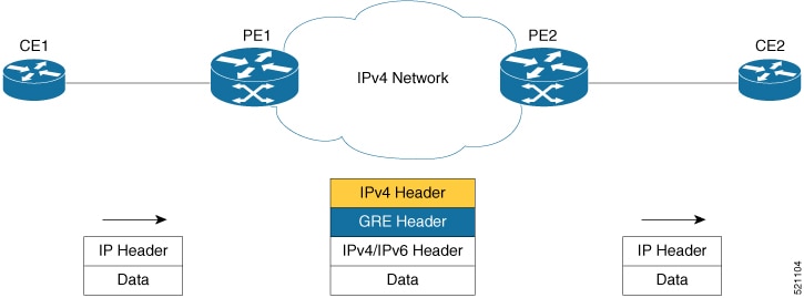
Generic Routing Encapsulation (GRE) is a tunneling protocol that provides a simple generic approach to transport packets of one protocol over another protocol by means of encapsulation. GRE encapsulates a payload, that is, an inner packet that should be delivered to a destination network inside an outer IP packet. The GRE tunnel behaves as virtual point-to-point link that has two endpoints identified by the tunnel source and tunnel destination address. The tunnel endpoints send payloads through GRE tunnels by routing encapsulated packets through intervening IP networks. Other IP routers along the way do not parse the payload (the inner packet); they only parse the outer IP packet as they forward it toward the GRE tunnel endpoint. Upon reaching the tunnel endpoint, GRE encapsulation is removed and the payload is forwarded to the packet's ultimate destination.
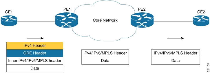
A tunnel configured using encapsulation mode performs encapsulation of IPv4/IPv6 payload inside the GRE header. A tunnel configured
using decapsulation mode performs the opposite. Here, outer GRE header is decapsulated and the inner IPv4/IPv6/MPLS payload
is forwarded to the next hop router. Both encapsulation and decapsulation tunnel interfaces collect statistics periodically.
The statistics can be displayed on demand using the CLI commands show interface tunnel-ip1 accounting and show policy-map type pbr address-family ipv4 statistics. For more information, see Unidirectional GRE Encapsulation (GREv4) and Unidirectional GRE Decapsulation (GREv4).
To perform load-balancing of GRE traffic in transit routers, a transit node distributes incoming GRE traffic evenly across all available ECMP links in a GRE tunnel topology. Furthermore, to determine traffic entropy, a hashing function uses GRE outer and inner header tuples such as source IP, destination IP, protocol, and router ID.
GRE encapsulation and decapsulation over BVI
|
Feature Name |
Release Information |
Description |
|---|---|---|
|
GRE encapsulation and decapsulation over BVI |
Release 24.4.1 |
Introduced in this release on: Fixed Systems (8200 [ASIC: P100], 8700 [ASIC: P100, K100])(select variants only*); Modular Systems (8800 [LC ASIC: P100])(select variants only*) *This feature is now supported on:
|
|
GRE encapsulation and decapsulation over BVI |
Release 7.5.4 |
You can now transport packets using the GRE protocol over Bridge-Group Virtual Interfaces (BVI). This feature uses GRE to encapsulate packets between two endpoints and transmit the encapsulated packets over a BVI interface. At the destination, the GRE packet is decapsulated. GRE encapsulation and decapsulation over BVI allows transmitting packets securely using network layer protocols while maintaining Layer 2 connectivity between the physical interfaces. |
From Cisco IOS XR Release 7.5.4, GRE packets are supported over a BVI interface. This support provides GRE encapsulation and decapsulation over the BVI interfaces.
The BVI is a virtual interface within the router that acts like a normal routed interface. The BVI does not support bridging itself, but acts as a gateway for the corresponding bridge-domain to a routed interface within the router. A BVI is associated with a single bridge domain and represents the link between the bridging and the routing domains on the router.
When using GRE over BVI, the GRE header is added to the original IP packet before it is sent to the BVI. The BVI then bridges the encapsulated packet to the destination interface, which is a BVI, physical interface, or a remote network.
When the encapsulated packet reaches its destination, the receiving interface performs GRE decapsulation, which involves removing the GRE header from the original IP packet. The resulting IP packet is then forwarded to its final destination.
For information on BVI, see the Integrated Routing and Bridging section in the L2VPN Configuration Guide for Cisco 8000 Series Routers.
Supported Features on a GRE Tunnel
GRE tunnel supports the following features:
-
GRE or IP-in-IP tunnels support 16 unique source addresses. These 16 unique source addresses are repeated multiple times to configure 1000 encapsulation tunnels or 64 decapsulation tunnels.
-
GRE encapsulation supports the following features:
-
IPv4/IPv6 over GRE IPv4 transport
-
MPLS PoP over GRE IPv4 transport
-
ABF (Access List Based Forwarding) v4/v6 over GRE
-
VRF (Virtual Routing and Forwarding) support over GRE
-
-
GRE decapsulation supports the following features:
-
PBR-based GRE decapsulation configuration
-
CLI-based GRE decapsulation configuration
-
IPv4/IPv6 over GRE decapsulation
-
MPLS/SRTE over GRE decapsulation
-
A GRE tunnel in decapsulation mode has only tunnel source configured, without any tunnel destination address. This decapsulated GRE tunnel behaves like a P2MP (Point-to-multipoint) tunnel, which means that an incoming GRE packet can have any source IP address and matching destination IP address to the tunnel source configured. However, once a source IP address is used for decapsulated P2MP tunnel, it cannot be re-used with other decapsulation tunnels.
-
-
The command
tunnel ttl disableis supported. This command controls TTL decrement of a packet being encapsulated. After configuring this command fo a tunnel interface, TTL value of incoming packet is not decremented by one, and original incoming packet is encapsulated without changing the TTL. By default,tunnel ttl disableisn’t configured. This means that the TTL of incoming packets is decremented by one before GRE encapsulation.For example, consider an incoming packet that had the TTL value equal to one. On GRE encapsulation, the TTL value is decremented by one and becomes zero. Therefore the router will discard the packet and send an ICMP message back to the originating host. Using this feature, you can disable TTL decrement and avoid the packet discard.
Configuration Example Router#configure Router(config)#interface tunnel-ip30016 Router(config-if)#tunnel ttl disable Router(config-if)#commit
Limitations for Configuring GRE Tunnels
This list describes the limitations for configuring GRE tunnels:
-
GRE tunnels configured without any decapsulation or encapsulation mode support only ERPSAN feature.
-
Don't create multiple GRE/IP-in-IP tunnels with the same pair of source and destination IP address or interface name. Configure all tunnels with unique source-destination pairs. In an encapsulation or decapsulation tunnel where only either source or destination is mentioned, the source-destination pair should also be unique when compared to other encapsulation or decapsulation tunnels.
-
Bi-directional GRE tunnel isn't supported.
-
Routing protocols over GRE tunnels aren't supported.
-
Multicast over GRE isn't supported.
-
GRE KA (Keep Alive) isn't supported.
-
GRE parameters such as MTU (Maximum Transmission Unit) and key functionalities aren't supported.
Configure GRE Tunnels
Configuring a GRE tunnel involves creating a tunnel interface and defining the tunnel source and destination. This example shows how to configure a GRE tunnel between source and destination. The router supports only uni-directional GRE with either encapsulation or decapsulation mode.
Router# configure
Router(config)# interface tunnel-ip1
Router(config-if)# ipv4 address 101.0.1.2 255.255.255.0
Router(config-if)# ipv6 address 101:0:1::2/64
Router(config-if)# tunnel mode gre ipv4 [encap | decap]
Router(config-if)# tunnel source 2.2.1.1
Router(config-if)# tunnel destination 2.2.2.1/32
Router(config-if)# commit
Router(config-if)# exit
To configure ABFv4/v6 over GRE:
router static
  address-family ipv4 unicast
  201.0.1.0/24 tunnel-ip1
  address-family ipv6 unicast
  201:0:1::0/64 tunnel-ip1

ipv4 access-list abf-gre
  1 permit ipv4 any any nexthop1 ipv4 201.0.1.2
ipv6 access-list abf6-gre
  1 permit ipv6 any any nexthop1 ipv6 201:0:1::2

interface HundredGigE0/0/0/24
  ipv4 address 24.0.1.1/24
  ipv6 address 24:0:1::1/64
  ipv4 access-group abf-gre ingress
  ipv6 access-group abf6-gre ingress
!
To configure MPLS PoP label over GRE:
router static
  address-family ipv4 unicast
  201.0.1.0/24 tunnel-ip1
  address-family ipv6 unicast
  201:0:1::0/64 tunnel-ip1

mpls static
  interface HundredGigE0/0/0/24
  lsp gre
    in-label 30501 allocate
    forward path 1 resolve-nexthop 201.0.1.2 out-label pop
!
 Note |
Bi-directional GRE tunnel supports only ERSPAN. |
 Feedback