-
- MPLS Traffic Engineering - LSP Attributes
- MPLS Traffic Engineering (TE) - Autotunnel Primary and Backup
- MPLS Traffic Engineering - AutoTunnel Mesh Groups
- MPLS Traffic Engineering - Verbatim Path Support
- MPLS Traffic Engineering - RSVP Hello State Timer
- MPLS Traffic Engineering Forwarding Adjacency
- MPLS Traffic Engineering (TE) - Class-based Tunnel Selection
- MPLS Traffic Engineering - Interarea Tunnels
- MPLS TE - Bundled Interface Support
- MPLS Traffic Engineering�Automatic Bandwidth Adjustment for TE Tunnels
- MPLS Point-to-Multipoint Traffic Engineering
- MPLS Traffic Engineering�Tunnel Source
-
- MPLS Traffic Engineering - Inter-AS TE
- MPLS Traffic Engineering - Shared Risk Link Groups
- MPLS Traffic Engineering (TE) - Autotunnel Primary and Backup
- MPLS Traffic Engineering (TE) - Path Protection
- MPLS Traffic Engineering (TE) - Fast Reroute (FRR) Link and Node Protection
- MPLS TE: Link and Node Protection, with RSVP Hellos Support (with Fast Tunnel Interface Down Detection)
- MPLS Traffic Engineering: BFD-triggered Fast Reroute (FRR)
-
- MPLS MTU Command Changes
- AToM Static Pseudowire Provisioning
- MPLS Pseudowire Status Signaling
- L2VPN Interworking
- L2VPN Pseudowire Redundancy
- L2VPN Pseudowire Switching
- VPLS Autodiscovery: BGP Based
- H-VPLS N-PE Redundancy for QinQ and MPLS Access
- L2VPN Multisegment Pseudowires
- QOS Policy Support on L2VPN ATM PVPs
- L2VPN: Pseudowire Preferential Forwarding
-
- Configuring MPLS Layer 3 VPNs
- MPLS VPN Half-Duplex VRF
- MPLS VPN�Show Running VRF
- MPLS VPN�VRF CLI for IPv4 and IPv6 VPNs
- MPLS VPN--BGP Local Convergence
- MPLS VPN�Route Target Rewrite
- MPLS VPN�Per VRF Label
- MPLS VPN 6VPE per VRF Label
- MPLS Multi-VRF (VRF Lite) Support
- BGP Best External
- BGP PIC Edge for IP and MPLS-VPN
- MPLS VPN - L3VPN over GRE
- Dynamic Layer-3 VPNs with Multipoint GRE Tunnels
- MPLS VPN over mGRE
-
- MPLS LSP Ping/Traceroute for LDP/TE, and LSP Ping for VCCV
- MPLS EM�MPLS LSP Multipath Tree Trace
- Pseudowire Emulation Edge-to-Edge MIBs for Ethernet, Frame Relay, and ATM Services
- MPLS Enhancements to Interfaces MIB
- MPLS Label Distribution Protocol MIB Version 8 Upgrade
- MPLS EM�MPLS LDP MIB - RFC 3815
- MPLS Label Switching Router MIB
- MPLS EM�MPLS LSR MIB - RFC 3813
- MPLS Traffic Engineering MIB
- MPLS Traffic Engineering - Fast Reroute MIB
- MPLS EM - TE MIB RFC 3812
- MPLS VPN�MIB Support
- MPLS EM - MPLS VPN MIB RFC4382 Upgrade
-
- MPLS High Availability: Overview
- MPLS High Availability: Command Changes
- MPLS LDP Graceful Restart
- NSF/SSO - MPLS LDP and LDP Graceful Restart
- NSF/SSO: MPLS VPN
- AToM Graceful Restart
- NSF/SSO�Any Transport over MPLS and AToM Graceful Restart
- NSF/SSO - MPLS TE and RSVP Graceful Restart
- ISSU MPLS Clients
- NSF/SSO/ISSU Support for VPLS
- NSF/SSO and ISSU - MPLS VPN 6VPE and 6PE
- Finding Feature Information
- Contents
- Prerequisites for MPLS Traffic Engineering: BFD-triggered Fast Reroute
- Restrictions for MPLS Traffic Engineering: BFD-triggered Fast Reroute
- Information About MPLS Traffic Engineering: BFD-triggered Fast Reroute
- How to Configure MPLS Traffic Engineering: BFD-triggered Fast Reroute
- Enabling BFD Support on the Router
- Enabling Fast Reroute on LSPs
- Creating a Backup Tunnel to the Next Hop or to the Next-Next Hop
- Assigning Backup Tunnels to a Protected Interface
- Enabling BFD on the Protected Interface
- Associating Backup Bandwidth and Pool Type with a Backup Tunnel
- Configuring Backup Bandwidth Protection
- Verifying That Fast Reroute Is Operational
- Configuration Examples for MPLS Traffic Engineering: BFD-triggered Fast Reroute
- Enabling BFD Support on the Router: Example
- Enabling Fast Reroute on LSPs: Example
- Creating a Backup Tunnel to the Next Hop: Example
- Creating an NNHOP Backup Tunnel: Example
- Assigning Backup Tunnels to a Protected Interface: Example
- Enabling BFD on the Protected Interface: Example
- Associating Backup Bandwidth and Pool Type with Backup Tunnels: Example
- Configuring Backup Bandwidth Protection: Example
- Additional References
- Feature Information for MPLS Traffic Engineering: BFD-triggered Fast Reroute
- Glossary
MPLS Traffic Engineering: BFD-triggered Fast Reroute
The MPLS Traffic Engineering: BFD-triggered Fast Reroute feature allows you to obtain link and node protection by using the Bidirectional Forwarding Detection (BFD) protocol to provide fast forwarding path failure detection times for all media types, encapsulations, topologies, and routing protocols. In addition to fast forwarding path failure detection, BFD provides a consistent failure detection method for network administrators.
To obtain link and node protection by using the Resource Reservation Protocol (RSVP) with Hellos support, refer to the MPLS TE: Link and Node Protection, with RSVP Hellos Support (with Fast Tunnel Interface Down Detection) process module. RSVP Hellos enable a router to detect when a neighboring node has gone down but its interface to that neighbor is still operational.
Finding Feature Information
Your software release may not support all the features documented in this module. For the latest feature information and caveats, see the release notes for your platform and software release. To find information about the features documented in this module, and to see a list of the releases in which each feature is supported, see the "Feature Information for MPLS Traffic Engineering: BFD-triggered Fast Reroute" section.
Use Cisco Feature Navigator to find information about platform support and Cisco IOS, Catalyst OS, and Cisco IOS XE software image support. To access Cisco Feature Navigator, go to http://www.cisco.com/go/cfn. An account on Cisco.com is not required.
Contents
•![]() Prerequisites for MPLS Traffic Engineering: BFD-triggered Fast Reroute
Prerequisites for MPLS Traffic Engineering: BFD-triggered Fast Reroute
•![]() Restrictions for MPLS Traffic Engineering: BFD-triggered Fast Reroute
Restrictions for MPLS Traffic Engineering: BFD-triggered Fast Reroute
•![]() Information About MPLS Traffic Engineering: BFD-triggered Fast Reroute
Information About MPLS Traffic Engineering: BFD-triggered Fast Reroute
•![]() How to Configure MPLS Traffic Engineering: BFD-triggered Fast Reroute
How to Configure MPLS Traffic Engineering: BFD-triggered Fast Reroute
•![]() Configuration Examples for MPLS Traffic Engineering: BFD-triggered Fast Reroute
Configuration Examples for MPLS Traffic Engineering: BFD-triggered Fast Reroute
•![]() Feature Information for MPLS Traffic Engineering: BFD-triggered Fast Reroute
Feature Information for MPLS Traffic Engineering: BFD-triggered Fast Reroute
Prerequisites for MPLS Traffic Engineering: BFD-triggered Fast Reroute
•![]() Configure BFD. Refer to the Bidirectional Forwarding Detection process module.
Configure BFD. Refer to the Bidirectional Forwarding Detection process module.
•![]() Enable MPLS TE on all relevant routers and interfaces.
Enable MPLS TE on all relevant routers and interfaces.
•![]() Configure MPLS TE tunnels.
Configure MPLS TE tunnels.
•![]() For additional prerequisites, refer to the MPLS TE: Link and Node Protection, with RSVP Hellos Support (with Fast Tunnel Interface Down Detection) process module.
For additional prerequisites, refer to the MPLS TE: Link and Node Protection, with RSVP Hellos Support (with Fast Tunnel Interface Down Detection) process module.
Restrictions for MPLS Traffic Engineering: BFD-triggered Fast Reroute
•![]() You cannot configure BFD and RSVP Hellos on the same interface.
You cannot configure BFD and RSVP Hellos on the same interface.
•![]() BFD may not be supported on some interfaces.
BFD may not be supported on some interfaces.
•![]() For additional restrictions, refer to the MPLS TE: Link and Node protection, with RSVP Hellos Support (with Fast Tunnel Interface Down Detection) process module.
For additional restrictions, refer to the MPLS TE: Link and Node protection, with RSVP Hellos Support (with Fast Tunnel Interface Down Detection) process module.
Information About MPLS Traffic Engineering: BFD-triggered Fast Reroute
•![]() BFD
BFD
BFD
BFD is a detection protocol designed to provide fast forwarding path failure detection times for all media types, encapsulations, topologies, and routing protocols. In addition to fast forwarding path failure detection, BFD provides a consistent failure detection method for network administrators. Because the network administrator can use BFD to detect forwarding path failures at a uniform rate, rather than the variable rates for different routing protocol Hello mechanisms, network profiling and planning will be easier, and reconvergence time will be consistent and predictable.
Fast Reroute
Fast Reroute (FRR) is a mechanism for protecting Multiprotocol Label Switching (MPLS) traffic engineering (TE) label switched paths (LSPs) from link and node failures by locally repairing the LSPs at the point of failure, allowing data to continue to flow on them while their headend routers attempt to establish new end-to-end LSPs to replace them. FRR locally repairs the protected LSPs by rerouting them over backup tunnels that bypass failed links or nodes.
Link Protection
Backup tunnels that bypass only a single link of the LSP's path provide link protection. They protect LSPs if a link along their path fails by rerouting the LSP's traffic to the next hop (bypassing the failed link). These are referred to as next-hop (NHOP) backup tunnels because they terminate at the LSP's next hop beyond the point of failure.
Node Protection
FRR provides node protection for LSPs. Backup tunnels that bypass next-hop nodes along LSP paths are called next-next-hop (NNHOP) backup tunnels because they terminate at the node following the next-hop node of the LSP paths, thereby bypassing the next-hop node. They protect LSPs if a node along their path fails by enabling the node upstream of the failure to reroute the LSPs and their traffic around the failed node to the next-next hop. FRR supports the use of RSVP Hellos to accelerate the detection of node failures. NNHOP backup tunnels also provide protection from link failures, because they bypass the failed link as well as the node.
Bandwidth Protection
NHOP and NNHOP backup tunnels can be used to provide bandwidth protection for rerouted LSPs. This is referred to as backup bandwidth. You can associate backup bandwidth with NHOP or NNHOP backup tunnels. This informs the router of the amount of backup bandwidth a particular backup tunnel can protect. When a router maps LSPs to backup tunnels, bandwidth protection ensures that an LSP uses a given backup tunnel only if there is sufficient backup bandwidth. The router selects which LSPs use which backup tunnels in order to provide maximum bandwidth protection. That is, the router determines the best way to map LSPs onto backup tunnels in order to maximize the number of LSPs that can be protected.
How to Configure MPLS Traffic Engineering: BFD-triggered Fast Reroute
This section assumes that you want to add FRR protection to a network in which MPLS TE LSPs are configured.
To review how to configure MPLS TE tunnels, see the MPLS Traffic Engineering: Interarea Tunnels process module.
The following sections describe how to use FRR to protect LSPs in your network from link or node failures. Each task is identified as either required or optional.

Note ![]() You can perform the configuration tasks in any order.
You can perform the configuration tasks in any order.
Note ![]() An NNHOP backup tunnel must not go via the NHOP backup tunnel.
An NNHOP backup tunnel must not go via the NHOP backup tunnel.
•![]() Enabling BFD Support on the Router (required)
Enabling BFD Support on the Router (required)
•![]() Enabling Fast Reroute on LSPs (required)
Enabling Fast Reroute on LSPs (required)
•![]() Creating a Backup Tunnel to the Next Hop or to the Next-Next Hop (required)
Creating a Backup Tunnel to the Next Hop or to the Next-Next Hop (required)
•![]() Assigning Backup Tunnels to a Protected Interface (required)
Assigning Backup Tunnels to a Protected Interface (required)
•![]() Enabling BFD on the Protected Interface (required)
Enabling BFD on the Protected Interface (required)
•![]() Associating Backup Bandwidth and Pool Type with a Backup Tunnel (optional)
Associating Backup Bandwidth and Pool Type with a Backup Tunnel (optional)
•![]() Configuring Backup Bandwidth Protection (optional)
Configuring Backup Bandwidth Protection (optional)
•![]() Verifying That Fast Reroute Is Operational (optional)
Verifying That Fast Reroute Is Operational (optional)
Enabling BFD Support on the Router
SUMMARY STEPS
1. ![]() enable
enable
2. ![]() configure terminal
configure terminal
3. ![]() ip rsvp signalling hello bfd
ip rsvp signalling hello bfd
DETAILED STEPS
Enabling Fast Reroute on LSPs
LSPs can use backup tunnels only if the LSPs have been configured as fast reroutable. To enable FRR on the LSP, enter the following commands at the headend of each LSP.
SUMMARY STEPS
1. ![]() enable
enable
2. ![]() configure terminal
configure terminal
3. ![]() interface tunnel number
interface tunnel number
4. ![]() tunnel mpls traffic-eng fast-reroute [bw-protect] [node-protect]
tunnel mpls traffic-eng fast-reroute [bw-protect] [node-protect]
DETAILED STEPS
Creating a Backup Tunnel to the Next Hop or to the Next-Next Hop
To create a backup tunnel to the next hop or to the next-next hop, enter the following commands on the node that will be the headend of the backup tunnel (that is, the node whose downstream link or node may fail). The node on which you enter these commands must be a supported platform. See the "Finding Feature Information" section.
Creating a backup tunnel is basically no different from creating any other tunnel.
Note ![]() When using the exclude-address command to specify the path for a backup tunnel, you must exclude an interface address to avoid a link (for creating an NHOP backup tunnel), or a router-ID address to avoid a node (for creating an NNHOP backup tunnel).
When using the exclude-address command to specify the path for a backup tunnel, you must exclude an interface address to avoid a link (for creating an NHOP backup tunnel), or a router-ID address to avoid a node (for creating an NNHOP backup tunnel).
SUMMARY STEPS
1. ![]() enable
enable
2. ![]() configure terminal
configure terminal
3. ![]() interface tunnel number
interface tunnel number
4. ![]() ip unnumbered type number
ip unnumbered type number
5. ![]() tunnel destination A.B.C.D
tunnel destination A.B.C.D
6. ![]() tunnel mode mpls traffic-eng
tunnel mode mpls traffic-eng
7. ![]() tunnel mpls traffic-eng path-option number {dynamic | explicit {name path-name | path-number}}[lockdown]
tunnel mpls traffic-eng path-option number {dynamic | explicit {name path-name | path-number}}[lockdown]
8. ![]() exit
exit
9. ![]() ip explicit-path name name
ip explicit-path name name
10. ![]() exclude-address address
exclude-address address
DETAILED STEPS
Assigning Backup Tunnels to a Protected Interface
To assign one or more backup tunnels to a protected interface, enter the following commands on the node that will be the headend of the backup tunnel (that is, the node whose downstream link or node may fail). The node on which you enter these commands must be a supported platform. See the "Finding Feature Information" section.
Note ![]() You must configure the interface to have an IP address and to enable the MPLS TE tunnel feature.
You must configure the interface to have an IP address and to enable the MPLS TE tunnel feature.
SUMMARY STEPS
1. ![]() enable
enable
2. ![]() configure terminal
configure terminal
3. ![]() interface type slot/port
interface type slot/port
4. ![]() mpls traffic-eng backup-path tunnel tunnel-id
mpls traffic-eng backup-path tunnel tunnel-id
DETAILED STEPS
|
|
|
|
|---|---|---|
Step 1 |
enable Router> enable |
Enables privileged EXEC mode. • |
Step 2 |
configure terminal Router# configure terminal |
Enters global configuration mode. |
Step 3 |
interface type slot/port Router(config)# interface Gi 9/1 |
Moves configuration to the physical interface level, directing subsequent configuration commands to the specific physical interface identified by the type value, and enters interface configuration mode. The slot and port values identify the slot and port being configured. The interface must be a supported interface. See the "Finding Feature Information" section. |
Step 4 |
mpls traffic-eng backup-path tunnel tunnel-id Router(config-if)# mpls traffic-eng backup-path tunnel2 |
Allows LSPs going out this interface to use this backup tunnel if there is a link or node failure. Note |
Enabling BFD on the Protected Interface
SUMMARY STEPS
1. ![]() enable
enable
2. ![]() configure terminal
configure terminal
3. ![]() interface type number
interface type number
4. ![]() ip rsvp signalling hello bfd
ip rsvp signalling hello bfd
5. ![]() bfd interval milliseconds min_rx milliseconds multiplier interval-multiplier
bfd interval milliseconds min_rx milliseconds multiplier interval-multiplier
DETAILED STEPS
Associating Backup Bandwidth and Pool Type with a Backup Tunnel
SUMMARY STEPS
1. ![]() enable
enable
2. ![]() configure terminal
configure terminal
3. ![]() interface tunnel number
interface tunnel number
4. ![]() tunnel mpls traffic-eng backup-bw {bandwidth | [sub-pool {bandwidth | Unlimited}][global-pool {bandwidth | Unlimited}]}[any {bandwidth | Unlimited}]
tunnel mpls traffic-eng backup-bw {bandwidth | [sub-pool {bandwidth | Unlimited}][global-pool {bandwidth | Unlimited}]}[any {bandwidth | Unlimited}]
DETAILED STEPS
Configuring Backup Bandwidth Protection
SUMMARY STEPS
1. ![]() enable
enable
2. ![]() configure terminal
configure terminal
3. ![]() interface tunnel number
interface tunnel number
4. ![]() tunnel mpls traffic-eng fast-reroute [bw-protect]
tunnel mpls traffic-eng fast-reroute [bw-protect]
5. ![]() exit
exit
6. ![]() mpls traffic-eng fast-reroute backup-prot-preemption optimize-bw
mpls traffic-eng fast-reroute backup-prot-preemption optimize-bw
DETAILED STEPS
Verifying That Fast Reroute Is Operational
Note ![]() To determine if FRR has been configured correctly, perform Steps 1 and 2.
To determine if FRR has been configured correctly, perform Steps 1 and 2.
Note ![]() If you created LSPs and performed the required configuration tasks but do not have operational backup tunnels (that is, the backup tunnels are not up or the LSPs are not associated with those backup tunnels), perform Step 3.
If you created LSPs and performed the required configuration tasks but do not have operational backup tunnels (that is, the backup tunnels are not up or the LSPs are not associated with those backup tunnels), perform Step 3.
Note ![]() To determine the status of BFD, perform Steps 9 through 11.
To determine the status of BFD, perform Steps 9 through 11.
SUMMARY STEPS
1. ![]() show mpls traffic-eng tunnels brief
show mpls traffic-eng tunnels brief
2. ![]() show ip rsvp sender detail
show ip rsvp sender detail
3. ![]() show mpls traffic-eng fast-reroute database
show mpls traffic-eng fast-reroute database
4. ![]() show mpls traffic-eng tunnels backup
show mpls traffic-eng tunnels backup
5. ![]() show mpls traffic-eng fast-reroute database
show mpls traffic-eng fast-reroute database
6. ![]() show ip rsvp reservation
show ip rsvp reservation
7. ![]() show ip rsvp hello
show ip rsvp hello
8. ![]() show ip rsvp interface detail
show ip rsvp interface detail
9. ![]() show ip rsvp hello bfd nbr
show ip rsvp hello bfd nbr
10. ![]() show ip rsvp hello bfd nbr detail
show ip rsvp hello bfd nbr detail
11. ![]() show ip rsvp hello bfd nbr summary
show ip rsvp hello bfd nbr summary
DETAILED STEPS
Step 1 ![]() show mpls traffic-eng tunnels brief
show mpls traffic-eng tunnels brief
Use this command to verify that backup tunnels are up:
Router# show mpls traffic-eng tunnels brief
Signalling Summary:
LSP Tunnels Process: running
RSVP Process: running
Forwarding: enabled
Periodic reoptimization: every 3600 seconds, next in 1706 seconds
TUNNEL NAME DESTINATION UP IF DOWN IF STATE/PROT
Router_t1 10.112.0.12 - Gi4/0/1 up/up
Router_t2 10.112.0.12 - unknown up/down
Router_t3 10.112.0.12 - unknown admin-down
Router_t1000 10.110.0.10 - unknown up/down
Router_t2000 10.110.0.10 - Gi4/0/1 up/up
Displayed 5 (of 5) heads, 0 (of 0) midpoints, 0 (of 0) tails
Step 2 ![]() show ip rsvp sender detail
show ip rsvp sender detail
Use this command to verify that LSPs are protected by the appropriate backup tunnels.
Following is sample output from the show ip rsvp sender detail command when the command is entered at the router acting as the point of local repair (PLR) before a failure:
Router# show ip rsvp sender detail
PATH:
Tun Dest: 10.10.0.6 Tun ID: 100 Ext Tun ID: 10.10.0.1
Tun Sender: 10.10.0.1 LSP ID: 31
Path refreshes:
arriving: from PHOP 10.10.7.1 on Et0/0 every 30000 msecs
Session Attr:
Setup Prio: 7, Holding Prio: 7
Flags: (0x7) Local Prot desired, Label Recording, SE Style
session Name: R1_t100
ERO: (incoming)
10.10.7.2 (Strict IPv4 Prefix, 8 bytes, /32)
10.10.0.6 (Strict IPv4 Prefix, 8 bytes, /32)
RRO:
10.10.7.1/32, Flags:0x0 (No Local Protection)
10.10.4.1/32, Flags:0x9 (Local Prot Avail/to NNHOP) !Available to NNHOP
10.10.1.1/32, Flags:0x0 (No Local Protection)
Traffic params - Rate: 10K bits/sec, Max. burst: 1K bytes
Min Policed Unit: 0 bytes, Max Pkt Size 4294967295 bytes
Fast-Reroute Backup info:
Inbound FRR: Not active
Outbound FRR: No backup tunnel selected
Path ID handle: 50000416.
Incoming policy: Accepted. Policy source(s): MPLS/TE
Status: Proxy-terminated
Step 3 ![]() show mpls traffic-eng fast-reroute database
show mpls traffic-eng fast-reroute database
Enter the clear ip rsvp hello instance counters command to verify the following:
•![]() MPLS TE FRR Node Protection has been enabled.
MPLS TE FRR Node Protection has been enabled.
•![]() A certain type of LSP can use a backup tunnel.
A certain type of LSP can use a backup tunnel.
The following command output displays the LSPs that are protected:
Router# show mpls traffic-eng fast-reroute database
Tunnel head end item frr information:
Protected tunnel In-label Out intf/label FRR intf/label Status
Tunnel500 Tun hd AT4/0.100:Untagg Tu501:20 ready
Prefix item frr information:
Prefix Tunnel In-label Out intf/label FRR intf/label Status
10.0.0.8/32 Tu500 18 AT4/0.100:Pop ta Tu501:20 ready
10.0.8.8/32 Tu500 19 AT4/0.100:Untagg Tu501:20 ready
10.8.9.0/24 Tu500 22 AT4/0.100:Untagg Tu501:20 ready
LSP midpoint item frr information:
LSP identifier In-label Out intf/label FRR intf/label Status
If Label Distribution Protocol (LDP) is not enabled, separate prefix items are not shown because all prefixes then use a single rewrite. To confirm that a particular IP prefix is FRR protected, even though it is not shown in this display, enter it within the show mpls forwarding-table ip-address detail command. The final line of the display will tell whether that prefix is protected:
Router# show mpls forwarding-table 10.0.0.11 32 detail
Local Outgoing Prefix Bytes tag Outgoing Next Hop
tag tag or VC or Tunnel Id switched interface
Tun hd Untagged 10.0.0.11/32 48 5/0 Gi5/0 point2point
MAC/Encaps=4/8, MTU=1520, Tag Stack{22}
48D18847 00016000
No output feature configured
Fast Reroute Protection via (Tu0, outgoing label 12304)
The following command output displays the LSPs that are protected when the FRR primary tunnel is over a Gigabit Ethernet interface and the backup tunnel is over a Gigabit Ethernet interface. As shown in Figure 1, interface Gigabit Ethernet 9/1 is protected by backup tunnel 501.
Figure 1 Protected LSPs
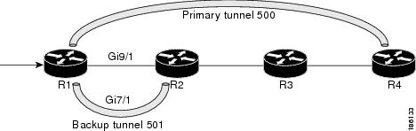
Figure 1 shows the following:
•![]() Primary tunnel 500—Path is R1 via Gigabit Ethernet9/1 to R2 to R3 to R4.
Primary tunnel 500—Path is R1 via Gigabit Ethernet9/1 to R2 to R3 to R4.
•![]() FRR backup tunnel 501—Path is R1 via Gigabit Ethernet7/1to R2.
FRR backup tunnel 501—Path is R1 via Gigabit Ethernet7/1to R2.
•![]() Interface Gigabit Ethernet9/1—Protected by backup tunnel 501.
Interface Gigabit Ethernet9/1—Protected by backup tunnel 501.
Router# show mpls traffic-eng fast-reroute database
Tunnel head end item frr information:
Protected tunnel In-label Out intf/label FRR intf/label Status
Tunnel500 Tun hd AT4/0.100:Untagg Tu501:20 ready
Prefix item frr information:
Prefix Tunnel In-label Out intf/label FRR intf/label Status
10.0.0.8/32 Tu500 18 AT4/0.100:Pop ta Tu501:20 ready
10.0.8.8/32 Tu500 19 AT4/0.100:Untagg Tu501:20 ready
10.8.9.0/24 Tu500 22 AT4/0.100:Untagg Tu501:20 ready
LSP midpoint item frr information:
LSP identifier In-label Out intf/label FRR intf/label Status
The following command output displays the LSPs that are protected when the FRR backup tunnel is over a Gigabit Ethernet interface.
Router# show mpls traffic-eng fast-reroute database
Tunnel head end item frr information:
Protected tunnel In-label Out intf/label FRR intf/label Status
Tunnel500 Tun hd PO2/0:Untagged Tu501:20 ready
Prefix item frr information:
Prefix Tunnel In-label Out intf/label FRR intf/label Status
10.0.0.8/32 Tu500 18 PO2/0:Pop tag Tu501:20 ready
10.0.8.8/32 Tu500 19 PO2/0:Untagged Tu501:20 ready
10.8.9.0/24 Tu500 22 PO2/0:Untagged Tu501:20 ready
LSP midpoint item frr information:
LSP identifier In-label Out intf/label FRR intf/label Status
Step 4 ![]() show mpls traffic-eng tunnels backup
show mpls traffic-eng tunnels backup
For backup tunnels to be operational, the LSP must be reroutable. At the headend of the LSP, enter the show run interface tunnel tunnel-number command. The output should include the tunnel mpls traffic-eng fast-reroute command. If it does not, enter this command for the tunnel.
On the router where the backup tunnels originate, enter the show mpls traffic-eng tunnels backup command. Following is sample command output:
Router# show mpls traffic-eng tunnels backup
Router_t578
LSP Head, Tunnel578, Admin: up, Oper: up
Src 10.55.55.55, Dest 10.88.88.88, Instance 1
Fast Reroute Backup Provided:
Protected i/fs: PO1/0, PO1/1, PO3/3
Protected lsps: 1
Backup BW: any pool unlimited; inuse: 100 kbps
Router_t5710
LSP Head, Tunnel5710, Admin: admin-down, Oper: down
Src 10.55.55.55, Dest 10.7.7.7, Instance 0
Fast Reroute Backup Provided:
Protected i/fs: PO1/1
Protected lsps: 0
Backup BW: any pool unlimited; inuse: 0 kbps
Router_t5711
LSP Head, Tunnel5711, Admin: up, Oper: up
Src 10.55.55.55, Dest 10.7.7.7, Instance 1
Fast Reroute Backup Provided:
Protected i/fs: PO1/0
Protected lsps: 2
Backup BW: any pool unlimited; inuse: 6010 kbps
The command output will allow you to verify the following:
•![]() Backup tunnel exists—Verify that there is a backup tunnel that terminates at this LSP's NHOP or NNHOP. Look for the LSP's NHOP or NNHOP in the Dest field.
Backup tunnel exists—Verify that there is a backup tunnel that terminates at this LSP's NHOP or NNHOP. Look for the LSP's NHOP or NNHOP in the Dest field.
•![]() Backup tunnel is up—To verify that the backup tunnel is up, look for "Up" in the Oper field.
Backup tunnel is up—To verify that the backup tunnel is up, look for "Up" in the Oper field.
•![]() Backup tunnel is associated with the LSP's interface—Verify that the interface for the LSP is allowed to use this backup tunnel. Look for the LSP's output interface in the protected i/fs field list.
Backup tunnel is associated with the LSP's interface—Verify that the interface for the LSP is allowed to use this backup tunnel. Look for the LSP's output interface in the protected i/fs field list.
•![]() Backup tunnel has sufficient bandwidth—If you restricted the amount of bandwidth a backup tunnel can hold, verify that the backup tunnel has sufficient bandwidth to hold the LSPs that would use this backup tunnel if there is a failure. The bandwidth of an LSP is defined by the line tunnel mpls traffic-eng bandwidth at the headend of the LSP. To determine the available bandwidth on a backup tunnel, look at the "cfg" and "inuse" fields. If there is insufficient backup bandwidth to accommodate the LSPs that would use this backup tunnel in the event of a failure, create an additional backup tunnel or increase the backup bandwidth of the existing tunnel by using the tunnel mpls traffic-eng bandwidth command.
Backup tunnel has sufficient bandwidth—If you restricted the amount of bandwidth a backup tunnel can hold, verify that the backup tunnel has sufficient bandwidth to hold the LSPs that would use this backup tunnel if there is a failure. The bandwidth of an LSP is defined by the line tunnel mpls traffic-eng bandwidth at the headend of the LSP. To determine the available bandwidth on a backup tunnel, look at the "cfg" and "inuse" fields. If there is insufficient backup bandwidth to accommodate the LSPs that would use this backup tunnel in the event of a failure, create an additional backup tunnel or increase the backup bandwidth of the existing tunnel by using the tunnel mpls traffic-eng bandwidth command.
Note ![]() In order to determine how much bandwidth is sufficient, offline capacity planning may be required.
In order to determine how much bandwidth is sufficient, offline capacity planning may be required.
Backup tunnel has appropriate bandwidth type—If you restricted the type of LSPs (subpool or global pool) that can use this backup tunnel, verify that the LSP is the appropriate type for the backup tunnel. The type of the LSP is defined by the line tunnel mpls traffic-eng bandwidth at the headend of this LSP. If this line contains the word "sub pool", then it uses subpool bandwidth; otherwise, it uses global pool bandwidth. Verify that the type matches the type the backup tunnel can hold by looking in the output of the tunnel mpls traffic-eng bandwidth command.
If none of the verification actions described succeed, enable debug by entering the debug ip rsvp fast-reroute command and the debug mpls traffic-eng fast-reroute command on the router that is the headend of the backup tunnel. Then do the following:
1. ![]() Enter the shutdown command for the primary tunnel.
Enter the shutdown command for the primary tunnel.
2. ![]() Enter the no shutdown command for the primary tunnel.
Enter the no shutdown command for the primary tunnel.
3. ![]() View the debug output.
View the debug output.
Step 5 ![]() show mpls traffic-eng fast-reroute database
show mpls traffic-eng fast-reroute database
Enter the clear ip rsvp hello instance counters command to verify the following:
•![]() MPLS TE FRR node protection has been enabled.
MPLS TE FRR node protection has been enabled.
•![]() A certain type of LSP can use a backup tunnel.
A certain type of LSP can use a backup tunnel.
The following command output displays the LSPs that are protected:
Router# show mpls traffic-eng fast-reroute database
Tunnel head end item frr information:
Protected Tunnel In-label intf/label FRR intf/label Status
Tunne1l0 Tun Gi5/0:Untagged Tu0:12304 ready
Prefix item frr information:
Prefix Tunnel In-label Out intf/label FRR intf/label Status
10.0.0.11/32 Tu110 Tun hd Gi5/0:Untagged Tu0:12304 ready
LSP midpoint frr information:
LSP identifier In-label Out intf/label FRR intf/label Status
10.0.0.12 1 [459] 16 Gi0/1:17 Tu2000:19 ready
Note ![]() If Label Distribution Protocol (LDP) is not enabled, separate prefix items are not shown because all prefixes then use a single rewrite. To confirm that a particular IP prefix is FRR protected, even though it is not shown in this display, enter it within the show mpls forwarding-table ip-address detail command. The final line of the display will tell whether that prefix is protected.
If Label Distribution Protocol (LDP) is not enabled, separate prefix items are not shown because all prefixes then use a single rewrite. To confirm that a particular IP prefix is FRR protected, even though it is not shown in this display, enter it within the show mpls forwarding-table ip-address detail command. The final line of the display will tell whether that prefix is protected.
Router# show mpls forwarding-table 10.0.0.11 32 detail
Local Outgoing Prefix Bytes tag Outgoing Next Hop
tag tag or VC or Tunnel Id switched interface
Tun hd Untagged 10.0.0.11/32 48 Gi5/0 point2point
MAC/Encaps=4/8, MTU=1520, Tag Stack{22}
48D18847 00016000
No output feature configured
Fast Reroute Protection via (Tu0, outgoing label 12304)
Step 6 ![]() show ip rsvp reservation detail
show ip rsvp reservation detail
Following is sample output from the show ip rsvp reservation detail command entered at the headend of a primary LSP. Entering the command at the headend of the primary LSP shows, among other things, the status of FRR (that is, local protection) at each hop this LSP traverses. The per-hop information is collected in the Record Route Object (RRO) that travels with the Resv message from the tail to the head.
Router# show ip rsvp reservation detail
Reservation:
Tun Dest: 10.1.1.1 Tun ID: 1 Ext Tun ID: 10.1.1.1
Tun Sender: 10.1.1.1 LSP ID: 104
Next Hop: 10.1.1.2 on Gi1/0
Label: 18 (outgoing)
Reservation Style is Shared-Explicit, QoS Service is Controlled-Load
Average Bitrate is 0 bits/sec, Maximum Burst is 1K bytes
Min Policed Unit: 0 bytes, Max Pkt Size: 0 bytes
RRO:
10.1.1.1/32, Flags:0x1 (Local Prot Avail/to NHOP)
Label subobject: Flags 0x1, C-Type 1, Label 18
10.1.1.1/32, Flags:0x0 (Local Prot Avail/In Use/Has BW/to NHOP)
Label subobject: Flags 0x1, C-Type 1, Label 16
10.1.1.2/32, Flags:0x0 (No Local Protection)
Label subobject: Flags 0x1, C-Type 1, Label 0
Resv ID handle: CD000404.
Policy: Accepted. Policy source(s): MPLS/TE
Notice the following about the primary LSP:
•![]() It has protection that uses an NHOP backup tunnel at its first hop.
It has protection that uses an NHOP backup tunnel at its first hop.
•![]() It has protection and is actively using an NHOP backup tunnel at its second hop.
It has protection and is actively using an NHOP backup tunnel at its second hop.
•![]() It has no local protection at its third hop.
It has no local protection at its third hop.
The RRO display shows the following information for each hop:
•![]() Whether local protection is available (that is, whether the LSP has selected a backup tunnel)
Whether local protection is available (that is, whether the LSP has selected a backup tunnel)
•![]() Whether local protection is in use (that is, whether the LSP is using its selected backup tunnel)
Whether local protection is in use (that is, whether the LSP is using its selected backup tunnel)
•![]() Whether the selected backup tunnel is an NHOP or NNHOP backup tunnel
Whether the selected backup tunnel is an NHOP or NNHOP backup tunnel
•![]() Whether the backup tunnel used at this hop provides bandwidth protection
Whether the backup tunnel used at this hop provides bandwidth protection
Step 7 ![]() show ip rsvp hello
show ip rsvp hello
Use this command to display hello status and statistics for FRR, reroute (hello state timer), and graceful restart. Following is sample output:
Router# show ip rsvp hello
Hello:
RSVP Hello for Fast-Reroute/Reroute: Enabled
Statistics: Disabled
BFD for Fast-Reroute/Reroute: Enabled
RSVP Hello for Graceful Restart: Disabled
Step 8 ![]() show ip rsvp interface detail
show ip rsvp interface detail
Use this command to display the interface configuration for Hello. Following is sample output:
Router# show ip rsv interface detail
Gi9/47:
RSVP: Enabled
Interface State: Up
Bandwidth:
Curr allocated: 0 bits/sec
Max. allowed (total): 0 bits/sec
Max. allowed (per flow): 0 bits/sec
Max. allowed for LSP tunnels using sub-pools (pool 1): 0 bits/sec
Set aside by policy (total): 0 bits/sec
Signalling:
DSCP value used in RSVP msgs: 0x3F
Number of refresh intervals to enforce blockade state: 4
Authentication: disabled
Key chain: <none>
Type: md5
Window size: 1
Challenge: disabled
FRR Extension:
Backup Path: Configured (or "Not Configured")
BFD Extension:
State: Disabled
Interval: Not Configured
RSVP Hello Extension:
State: Disabled
Refresh Interval: FRR: 200 , Reroute: 2000
Missed Acks: FRR: 4 , Reroute: 4
DSCP in HELLOs: FRR: 0x30 , Reroute: 0x30
Step 9 ![]() show ip rsvp hello bfd nbr
show ip rsvp hello bfd nbr
Use this command to display information about all MPLS traffic engineering link and node protected neighbors that use the BFD protocol. Following is sample output. The command output is the same as the show ip rsvp hello bfd nbr summary command output.
Router# show ip rsvp hello bfd nbr
Client Neighbor I/F State LostCnt LSPs
FRR 10.0.0.6 Gi9/47 Up 0 1
Step 10 ![]() show ip rsvp hello bfd nbr detail
show ip rsvp hello bfd nbr detail
Use this command to display detailed information about all MPLS traffic engineering link and node protected neighbors that use the BFD protocol:
Router# show ip rsvp hello bfd nbr detail
Hello Client Neighbors
Remote addr 10.0.0.6, Local addr 10.0.0.7
Type: Active
I/F: Gi9/47
State: Up (for 00:09:41)
Clients: FRR
LSPs protecting: 1 (frr: 1, hst upstream: 0 hst downstream: 0)
Communication with neighbor lost: 0
Step 11 ![]() show ip rsvp hello bfd nbr summary
show ip rsvp hello bfd nbr summary
Use this command to display summarized information about all MPLS traffic engineering link and node protected neighbors that use the BFD protocol. The command output is the same as the show ip rsvp hello bfd nbr summary command output.
Router# show ip rsvp hello bfd nbr summary
Client Neighbor I/F State LostCnt LSPs
FRR 10.0.0.6 Gi9/47 Up 0 1
Configuration Examples for MPLS Traffic Engineering: BFD-triggered Fast Reroute
This section provides the following configuration examples:
•![]() Enabling BFD Support on the Router: Example
Enabling BFD Support on the Router: Example
•![]() Enabling Fast Reroute on LSPs: Example
Enabling Fast Reroute on LSPs: Example
•![]() Creating a Backup Tunnel to the Next Hop: Example
Creating a Backup Tunnel to the Next Hop: Example
•![]() Assigning Backup Tunnels to a Protected Interface: Example
Assigning Backup Tunnels to a Protected Interface: Example
•![]() Enabling BFD on the Protected Interface: Example
Enabling BFD on the Protected Interface: Example
•![]() Associating Backup Bandwidth and Pool Type with Backup Tunnels: Example
Associating Backup Bandwidth and Pool Type with Backup Tunnels: Example
•![]() Configuring Backup Bandwidth Protection: Example
Configuring Backup Bandwidth Protection: Example
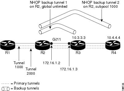
The examples relate to the illustration shown in Figure 2.
Figure 2 Backup Tunnels
Enabling BFD Support on the Router: Example
The following example enables the BFD protocol on the router:
Router(config)# ip rsvp signalling hello bfd
Enabling Fast Reroute on LSPs: Example
On router R1, enter interface configuration mode for each tunnel to be protected (Tunnel 1000 and Tunnel 2000). Enable these tunnels to use a backup tunnel in case of a link or node failure along their paths.
Tunnel 1000 will use ten units of bandwidth from the subpool.
Tunnel 2000 will use five units of bandwidth from the global pool. The "bandwidth protection desired" bit and the "node protection desired bit" have been set by specifying bw-prot and node-prot, respectively, in the tunnel mpls traffic-eng fast-reroute command.
Router(config)# interface tunnel 1000
Router(config-if)# tunnel mpls traffic-eng fast-reroute
Router(config-if)# tunnel mpls traffic-eng bandwidth sub-pool 10
Router(config)# interface tunnel 2000
Router(config-if)# tunnel mpls traffic-eng fast-reroute bw-protect node-protect
Router(config-if)# tunnel mpls traffic-eng bandwidth 5
Creating a Backup Tunnel to the Next Hop: Example
On router R2, create an NHOP backup tunnel to R3. This backup tunnel should avoid using the link 10.1.1.2.
Router(config)# ip explicit-path name avoid-protected-link
Router(cfg-ip-expl-path)# exclude-address 10.1.1.2
Explicit Path name avoid-protected-link:
____1: exclude-address 10.1.1.2
Router(cfg-ip_expl-path)# end
Router(config)# interface tunnel 1
Router(config-if)# ip unnumbered loopback 0
Router(config-if)# tunnel destination 10.3.3.3
Router(config-if)# tunnel mode mpls traffic-eng
Router(config-if)# tunnel mpls traffic-eng path-option 1 explicit avoid-protected-link
Creating an NNHOP Backup Tunnel: Example
On router R2, create an NNHOP backup tunnel to R4. This backup tunnel should avoid R3.
Router(config)# ip explicit-path name avoid-protected-node
Router(cfg-ip-expl-path)# exclude-address 10.3.3.3
Explicit Path name avoid-protected-node:
____1: exclude-address 10.3.3.3
Router(cfg-ip_expl-path)# end
Router(config)# interface tunnel2
Router(config-if)# ip unnumbered loopback0
Router(config-if)# tunnel destination 10.4.4.4
Router(config-if)# tunnel mode mpls traffic-eng0
Router(config-if)# tunnel mpls traffic-eng path-option 1 explicit avoid-protected-node
Assigning Backup Tunnels to a Protected Interface: Example
On router R2, associate both backup tunnels with interface Gigabit Ethernet 5/0:
Router(config)# interface Gi5/0
Router(config-if)# mpls traffic-eng backup-path tunnel 1
Router(config-if)# mpls traffic-eng backup-path tunnel 2
Enabling BFD on the Protected Interface: Example
BFD is enabled on interface Gigabit Ethernet 9/47:
Router(config)# interface Gi9/47
Router(config-if)# ip rsvp signalling hello bfd
Router(config-if)# bfd interval 100 min_rx 100 multiplier 4
Associating Backup Bandwidth and Pool Type with Backup Tunnels: Example
Backup tunnel 1 is to be used only by LSPs that take their bandwidth from the global pool. It does not provide bandwidth protection. Backup tunnel 2 is to be used only by LSPs that take their bandwidth from the subpool. Backup tunnel 2 provides bandwidth protection for up to 1000 units.
Router(config)# interface tunnel 1
Router(config-if)# tunnel mpls traffic-eng backup-bw global-pool Unlimited
Router(config)# interface tunnel 2
Router(config-if)# tunnel mpls traffic-eng backup-bw sub-pool 1000
Configuring Backup Bandwidth Protection: Example
In the following example, backup bandwidth protection is configured:
Note ![]() This global configuration is required only to change the backup protection preemption algorithm from minimize the number of LSPs that are demoted to minimize the amount of bandwidth that is wasted.
This global configuration is required only to change the backup protection preemption algorithm from minimize the number of LSPs that are demoted to minimize the amount of bandwidth that is wasted.
Router(config-if)# tunnel mpls traffic-eng fast-reroute bw-protect
Router(config)# mpls traffic-eng fast-reroute backup-prot-preemption optimize-bw
Additional References
Related Documents
Standards
|
|
|
|---|---|
No new or modified standards are supported by this feature, and support for existing standards has not been modified by this feature. |
— |
MIBs
RFCs
|
|
|
|---|---|
No new or modified RFCs are supported by this feature, and support for existing RFCs has not been modified by this feature. |
— |
Technical Assistance
Feature Information for MPLS Traffic Engineering: BFD-triggered Fast Reroute
Table 1 lists the release history for this feature.
Not all commands may be available in your Cisco IOS software release. For release information about a specific command, see the command reference documentation.
Use Cisco Feature Navigator to find information about platform support and software image support. Cisco Feature Navigator enables you to determine which Cisco IOS, Catalyst OS, and Cisco IOS XE software images support a specific software release, feature set, or platform. To access Cisco Feature Navigator, go to http://www.cisco.com/go/cfn. An account on Cisco.com is not required.
Note ![]() Table 1 lists only the Cisco IOS software release that introduced support for a given feature in a given Cisco IOS software release train. Unless noted otherwise, subsequent releases of that Cisco IOS software release train also support that feature.
Table 1 lists only the Cisco IOS software release that introduced support for a given feature in a given Cisco IOS software release train. Unless noted otherwise, subsequent releases of that Cisco IOS software release train also support that feature.
Glossary
backup bandwidth—The usage of NHOP and NNHOP backup tunnels to provide bandwidth protection for rerouted LSPs.
backup tunnel—An MPLS TE tunnel used to protect other (primary) tunnels' traffic when a link or node failure occurs.
bandwidth—The available traffic capacity of a link.
fast reroute—Procedures that enable temporary routing around a failed link or node while a new LSP is being established at the headend.
global pool—The total bandwidth allocated to an MPLS traffic engineering link or node.
headend—The router that originates and maintains a given LSP. This is the first router in the LSP's path.
hop—Passage of a data packet between two network nodes (for example, between two routers).
instance—A Hello instance implements the RSVP Hello extensions for a given router interface address and remote IP address. Active Hello instances periodically send Hello Request messages, expecting Hello ACK messages in response. If the expected Ack message is not received, the active Hello instance declares that the neighbor (remote IP address) is unreachable (that is, it is lost). This can cause LSPs crossing this neighbor to be fast rerouted.
interface—A network connection.
link—A point-to-point connection between adjacent nodes. There can be more than one link between adjacent nodes. A network communications channel consisting of a circuit or transmission path and all related equipment between a sender and a receiver. Sometimes referred to as a line or a transmission link.
LSP—label-switched path. A configured connection between two routers, in which label switching is used to carry the packets. The purpose of an LSP is to carry data packets.
MPLS—Multiprotocol Label Switching. Packet-forwarding technology, used in the network core, that applies data link layer labels to tell switching nodes how to forward data, resulting in faster and more scalable forwarding than network layer routing normally can do.
NHOP—next hop. The next downstream node along an LSP's path.
NHOP backup tunnel—next-hop backup tunnel. Backup tunnel terminating at the LSP's next hop beyond the point of failure, and originating at the hop immediately upstream of the point of failure. It bypasses a failed link, and is used to protect primary LSPs that were using this link before the failure.
NNHOP—next-next hop. The node after the next downstream node along an LSP's path.
NNHOP backup tunnel—next-next-hop backup tunnel. Backup tunnel terminating at the LSP's next-next hop beyond the point of failure, and originating at the hop immediately upstream of the point of failure. It bypasses a failed link or node, and is used to protect primary LSPs that were using this link or node before the failure.
node—Endpoint of a network connection or a junction common to two or more lines in a network. Nodes can be interconnected by links, and serve as control points in the network. Computers on a network, or any endpoint or a junction common to two or more lines in a network. Nodes can be processors, controllers, or workstations.
primary LSP—The last LSP originally signaled over the protected interface before the failure. The LSP before the failure.
primary tunnel—Tunnel whose LSP may be fast rerouted if there is a failure. Backup tunnels cannot be primary tunnels.
protected interface—An interface that has one or more backup tunnels associated with it.
redundancy—The duplication of devices, services, or connections so that, in the event of a failure, the redundant devices, services, or connections can perform the work of those that failed.
RSVP—Resource Reservation Protocol. An IETF protocol used for signaling requests (setting up reservations) for Internet services by a customer before that customer is permitted to transmit data over that portion of the network.
state—Information that a router must maintain about each LSP. The information is used for rerouting tunnels.
subpool—The more restrictive bandwidth in an MPLS traffic engineering link or node. The subpool is a portion of the link or node's overall global pool bandwidth.
tailend—The router upon which an LSP is terminated. This is the last router in the LSP's path.
tunnel—Secure communications path between two peers, such as two routers.
unlimited backup bandwidth—Backup tunnels that provide no bandwidth (best-effort) protection (that is, they provide best-effort protection).
Cisco and the Cisco Logo are trademarks of Cisco Systems, Inc. and/or its affiliates in the U.S. and other countries. A listing of Cisco's trademarks can be found at www.cisco.com/go/trademarks. Third party trademarks mentioned are the property of their respective owners. The use of the word partner does not imply a partnership relationship between Cisco and any other company. (1005R)
Any Internet Protocol (IP) addresses used in this document are not intended to be actual addresses. Any examples, command display output, and figures included in the document are shown for illustrative purposes only. Any use of actual IP addresses in illustrative content is unintentional and coincidental.
© 2008—2009 Cisco Systems, Inc. All rights reserved.
 Feedback