-
- MPLS Traffic Engineering - LSP Attributes
- MPLS Traffic Engineering (TE) - Autotunnel Primary and Backup
- MPLS Traffic Engineering - AutoTunnel Mesh Groups
- MPLS Traffic Engineering - Verbatim Path Support
- MPLS Traffic Engineering - RSVP Hello State Timer
- MPLS Traffic Engineering Forwarding Adjacency
- MPLS Traffic Engineering (TE) - Class-based Tunnel Selection
- MPLS Traffic Engineering - Interarea Tunnels
- MPLS TE - Bundled Interface Support
- MPLS Traffic Engineering�Automatic Bandwidth Adjustment for TE Tunnels
- MPLS Point-to-Multipoint Traffic Engineering
- MPLS Traffic Engineering�Tunnel Source
-
- MPLS Traffic Engineering - Inter-AS TE
- MPLS Traffic Engineering - Shared Risk Link Groups
- MPLS Traffic Engineering (TE) - Autotunnel Primary and Backup
- MPLS Traffic Engineering (TE) - Path Protection
- MPLS Traffic Engineering (TE) - Fast Reroute (FRR) Link and Node Protection
- MPLS TE: Link and Node Protection, with RSVP Hellos Support (with Fast Tunnel Interface Down Detection)
- MPLS Traffic Engineering: BFD-triggered Fast Reroute (FRR)
-
- MPLS MTU Command Changes
- AToM Static Pseudowire Provisioning
- MPLS Pseudowire Status Signaling
- L2VPN Interworking
- L2VPN Pseudowire Redundancy
- L2VPN Pseudowire Switching
- VPLS Autodiscovery: BGP Based
- H-VPLS N-PE Redundancy for QinQ and MPLS Access
- L2VPN Multisegment Pseudowires
- QOS Policy Support on L2VPN ATM PVPs
- L2VPN: Pseudowire Preferential Forwarding
-
- Configuring MPLS Layer 3 VPNs
- MPLS VPN Half-Duplex VRF
- MPLS VPN�Show Running VRF
- MPLS VPN�VRF CLI for IPv4 and IPv6 VPNs
- MPLS VPN--BGP Local Convergence
- MPLS VPN�Route Target Rewrite
- MPLS VPN�Per VRF Label
- MPLS VPN 6VPE per VRF Label
- MPLS Multi-VRF (VRF Lite) Support
- BGP Best External
- BGP PIC Edge for IP and MPLS-VPN
- MPLS VPN - L3VPN over GRE
- Dynamic Layer-3 VPNs with Multipoint GRE Tunnels
- MPLS VPN over mGRE
-
- MPLS LSP Ping/Traceroute for LDP/TE, and LSP Ping for VCCV
- MPLS EM�MPLS LSP Multipath Tree Trace
- Pseudowire Emulation Edge-to-Edge MIBs for Ethernet, Frame Relay, and ATM Services
- MPLS Enhancements to Interfaces MIB
- MPLS Label Distribution Protocol MIB Version 8 Upgrade
- MPLS EM�MPLS LDP MIB - RFC 3815
- MPLS Label Switching Router MIB
- MPLS EM�MPLS LSR MIB - RFC 3813
- MPLS Traffic Engineering MIB
- MPLS Traffic Engineering - Fast Reroute MIB
- MPLS EM - TE MIB RFC 3812
- MPLS VPN�MIB Support
- MPLS EM - MPLS VPN MIB RFC4382 Upgrade
-
- MPLS High Availability: Overview
- MPLS High Availability: Command Changes
- MPLS LDP Graceful Restart
- NSF/SSO - MPLS LDP and LDP Graceful Restart
- NSF/SSO: MPLS VPN
- AToM Graceful Restart
- NSF/SSO�Any Transport over MPLS and AToM Graceful Restart
- NSF/SSO - MPLS TE and RSVP Graceful Restart
- ISSU MPLS Clients
- NSF/SSO/ISSU Support for VPLS
- NSF/SSO and ISSU - MPLS VPN 6VPE and 6PE
Cisco IOS Multiprotocol Label Switching Configuration Guide, Release 12.2SR
Bias-Free Language
The documentation set for this product strives to use bias-free language. For the purposes of this documentation set, bias-free is defined as language that does not imply discrimination based on age, disability, gender, racial identity, ethnic identity, sexual orientation, socioeconomic status, and intersectionality. Exceptions may be present in the documentation due to language that is hardcoded in the user interfaces of the product software, language used based on RFP documentation, or language that is used by a referenced third-party product. Learn more about how Cisco is using Inclusive Language.
- Updated:
- February 12, 2008
Chapter: MPLS Traffic Engineering (TE) - Fast Reroute (FRR) Link and Node Protection
- Finding Feature Information
- Contents
- Prerequisites for MPLS Traffic Engineering—Fast Reroute Link and Node Protection
- Restrictions for MPLS Traffic Engineering—Fast Reroute Link and Node Protection
- Information About MPLS Traffic Engineering—Fast Reroute Link and Node Protection
- Fast Reroute
- Link Protection
- Node Protection
- Bandwidth Protection
- RSVP Hello
- Features of MPLS Traffic Engineering—Fast Reroute Link and Node Protection
- Backup Tunnel Support
- Backup Bandwidth Protection
- RSVP Hello
- Fast Reroute Operation
- Fast Reroute Activation
- Backup Tunnels Terminating at Different Destinations
- Backup Tunnels Terminating at the Same Destination
- Backup Tunnel Selection Procedure
- Bandwidth Protection
- Load Balancing on Limited-Bandwidth Backup Tunnels
- Load Balancing on Unlimited-Bandwidth Backup Tunnels
- Pool Type and Backup Tunnels
- Tunnel Selection Priorities
- Bandwidth Protection Considerations
- Enabling Fast Reroute on LSPs
- Creating a Backup Tunnel to the Next Hop or to the Next-Next Hop
- Assigning Backup Tunnels to a Protected Interface
- Associating Backup Bandwidth and Pool Type with a Backup Tunnel
- Configuring Backup Bandwidth Protection
- Configuring an Interface for Fast Link and Node Failure Detection
- Verifying That Fast Reroute Is Operational
- Enabling Fast Reroute for all Tunnels: Example
- Creating an NHOP Backup Tunnel: Example
- Creating an NNHOP Backup Tunnel: Example
- Assigning Backup Tunnels to a Protected Interface: Example
- Associating Backup Bandwidth and Pool Type with Backup Tunnels: Example
- Configuring Backup Bandwidth Protection: Example
- Configuring an Interface for Fast Link and Node Failure Detection: Example
- Configuring RSVP Hello and POS Signals: Example
MPLS Traffic Engineering—Fast Reroute Link and Node Protection
The MPLS Traffic Engineering—Fast Reroute Link and Node Protectionfeature provides link protection (backup tunnels that bypass only a single link of the label-switched path (LSP)), node protection (backup tunnels that bypass next-hop nodes along LSPs), and the following Fast Reroute (FRR) features:
•![]() Backup tunnel support
Backup tunnel support
•![]() Backup bandwidth protection
Backup bandwidth protection
•![]() Resource Reservation Protocol (RSVP) Hellos
Resource Reservation Protocol (RSVP) Hellos
Finding Feature Information
Your software release may not support all the features documented in this module. For the latest feature information and caveats, see the release notes for your platform and software release. To find information about the features documented in this module, and to see a list of the releases in which each feature is supported, see the "Feature Information for MPLS Traffic Engineering—Fast Reroute Link and Node Protection" section.
Use Cisco Feature Navigator to find information about platform support and Cisco IOS and Catalyst OS software image support. To access Cisco Feature Navigator, go to http://www.cisco.com/go/cfn. An account on Cisco.com is not required.
Contents
•![]() Prerequisites for MPLS Traffic Engineering—Fast Reroute Link and Node Protection
Prerequisites for MPLS Traffic Engineering—Fast Reroute Link and Node Protection
•![]() Restrictions for MPLS Traffic Engineering—Fast Reroute Link and Node Protection
Restrictions for MPLS Traffic Engineering—Fast Reroute Link and Node Protection
•![]() Information About MPLS Traffic Engineering—Fast Reroute Link and Node Protection
Information About MPLS Traffic Engineering—Fast Reroute Link and Node Protection
•![]() How to Configure MPLS Traffic Engineering—Fast Reroute (FRR) Link and Node Protection
How to Configure MPLS Traffic Engineering—Fast Reroute (FRR) Link and Node Protection
•![]() Configuration Examples for MPLS Traffic Engineering—Fast Reroute (FRR) Link and Node Protection
Configuration Examples for MPLS Traffic Engineering—Fast Reroute (FRR) Link and Node Protection
•![]() Feature Information for MPLS Traffic Engineering—Fast Reroute Link and Node Protection
Feature Information for MPLS Traffic Engineering—Fast Reroute Link and Node Protection
Prerequisites for MPLS Traffic Engineering—Fast Reroute Link and Node Protection
Your network must support the following Cisco IOS features:
•![]() IP Cisco Express Forwarding
IP Cisco Express Forwarding
•![]() Multiprotocol Label Switching (MPLS)
Multiprotocol Label Switching (MPLS)
Your network must support at least one of the following protocols:
•![]() Intermediate System-to-Intermediate System (IS-IS)
Intermediate System-to-Intermediate System (IS-IS)
•![]() Open Shortest Path First (OSPF)
Open Shortest Path First (OSPF)
Before configuring FRR link and node protection, it is assumed that you have done the following tasks but you do not have to already have configured MPLS traffic engineering (TE) tunnels:
•![]() Enabled MPLS TE on all relevant routers and interfaces
Enabled MPLS TE on all relevant routers and interfaces
•![]() Configured MPLS TE tunnels
Configured MPLS TE tunnels
Restrictions for MPLS Traffic Engineering—Fast Reroute Link and Node Protection
•![]() Interfaces must use MPLS Global Label Allocation.
Interfaces must use MPLS Global Label Allocation.
•![]() Backup tunnel headend and tailend routers must implement FRR as described in draft-pan-rsvp-fastreroute-00.txt.
Backup tunnel headend and tailend routers must implement FRR as described in draft-pan-rsvp-fastreroute-00.txt.
•![]() Backup tunnels are not protected. If an LSP is actively using a backup tunnel and the backup tunnel fails, the LSP is torn down.
Backup tunnels are not protected. If an LSP is actively using a backup tunnel and the backup tunnel fails, the LSP is torn down.
•![]() LSPs that are actively using backup tunnels are not considered for promotion. If an LSP is actively using a backup tunnel and a better backup tunnel becomes available, the active LSP is not switched to the better backup tunnel.
LSPs that are actively using backup tunnels are not considered for promotion. If an LSP is actively using a backup tunnel and a better backup tunnel becomes available, the active LSP is not switched to the better backup tunnel.
•![]() You cannot enable FRR Hellos on a router that also has Resource Reservation Protocol (RSVP) Graceful Restart enabled.
You cannot enable FRR Hellos on a router that also has Resource Reservation Protocol (RSVP) Graceful Restart enabled.
•![]() (Applicable only to Release 12.2.) You cannot enable primary one-hop autotunnels, backup autotunnels, or autotunnel mesh groups on a router that is also configured with stateful switchover (SSO) redundancy. This restriction does not prevent an MPLS TE tunnel that is automatically configured by TE autotunnel from being successfully recovered by any midpoint router along the LSP's path if the router experiences an SSO switchover.
(Applicable only to Release 12.2.) You cannot enable primary one-hop autotunnels, backup autotunnels, or autotunnel mesh groups on a router that is also configured with stateful switchover (SSO) redundancy. This restriction does not prevent an MPLS TE tunnel that is automatically configured by TE autotunnel from being successfully recovered by any midpoint router along the LSP's path if the router experiences an SSO switchover.
•![]() MPLS TE LSPs that are fast reroutable cannot be successfully recovered if the LSPs are FRR active and the Point of Local Repair (PLR) router experiences an SSO.
MPLS TE LSPs that are fast reroutable cannot be successfully recovered if the LSPs are FRR active and the Point of Local Repair (PLR) router experiences an SSO.
•![]() When SSO (stateful switchover) occurs on a router, the switchover process must complete before FRR (fast reroute) can complete successfully. In a testing environment, allow approximately 2 minutes for TE SSO recovery to complete before manually triggering FRR. To check the TE SSO status, use the show ip rsvp high-availability summary command. Note the status of the HA state field.
When SSO (stateful switchover) occurs on a router, the switchover process must complete before FRR (fast reroute) can complete successfully. In a testing environment, allow approximately 2 minutes for TE SSO recovery to complete before manually triggering FRR. To check the TE SSO status, use the show ip rsvp high-availability summary command. Note the status of the HA state field.
–![]() When SSO is in the process of completing, this field will display 'Recovering'.
When SSO is in the process of completing, this field will display 'Recovering'.
–![]() When the SSO process has completed, this field will display 'Active'.
When the SSO process has completed, this field will display 'Active'.
Information About MPLS Traffic Engineering—Fast Reroute Link and Node Protection
To configure MPLS Traffic Engineering—Fast Reroute Link and Node Protection, you need to understand the following concepts:
•![]() Features of MPLS Traffic Engineering—Fast Reroute Link and Node Protection
Features of MPLS Traffic Engineering—Fast Reroute Link and Node Protection
Fast Reroute
Fast Reroute (FRR) is a mechanism for protecting MPLS TE LSPs from link and node failures by locally repairing the LSPs at the point of failure, allowing data to continue to flow on them while their headend routers attempt to establish new end-to-end LSPs to replace them. FRR locally repairs the protected LSPs by rerouting them over backup tunnels that bypass failed links or node.
Link Protection
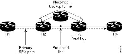
Backup tunnels that bypass only a single link of the LSP's path provide link protection. They protect LSPs if a link along their path fails by rerouting the LSP's traffic to the next hop (bypassing the failed link). These are referred to as next-hop (NHOP) backup tunnels because they terminate at the LSP's next hop beyond the point of failure. Figure 1 illustrates an NHOP backup tunnel.
Figure 1 NHOP Backup Tunnel
Node Protection
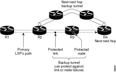
FRR provides node protection for LSPs. Backup tunnels that bypass next-hop nodes along LSP paths are called next-next-hop (NNHOP) backup tunnels because they terminate at the node following the next-hop node of the LSP paths, thereby bypassing the next-hop node. They protect LSPs if a node along their path fails by enabling the node upstream of the failure to reroute the LSPs and their traffic around the failed node to the next-next hop. FRR supports the use of RSVP Hellos to accelerate the detection of node failures. NNHOP backup tunnels also provide protection from link failures, because they bypass the failed link and the node.
Figure 2 illustrates an NNHOP backup tunnel.
Figure 2 NNHOP Backup Tunnel
If an LSP is using a backup tunnel and something changes so that the LSP is no longer appropriate for the backup tunnel, the LSP is torn down. Such changes are the following:
•![]() Backup bandwidth of the backup tunnel is reduced.
Backup bandwidth of the backup tunnel is reduced.
•![]() Backup bandwidth type of backup tunnel is changed to a type that is incompatible with the primary LSP.
Backup bandwidth type of backup tunnel is changed to a type that is incompatible with the primary LSP.
•![]() Primary LSP is modified so that FRR is disabled. (The no mpls traffic-eng fast-reroute command is entered.)
Primary LSP is modified so that FRR is disabled. (The no mpls traffic-eng fast-reroute command is entered.)
Bandwidth Protection
NHOP and NNHOP backup tunnels can be used to provide bandwidth protection for rerouted LSPs. This is referred to as backup bandwidth. You can associate backup bandwidth with NHOP or NNHOP backup tunnels. This informs the router of the amount of backup bandwidth a particular backup tunnel can protect. When a router maps LSPs to backup tunnels, bandwidth protection ensures that an LSP uses a given backup tunnel only if there is sufficient backup bandwidth. The router selects which LSPs use which backup tunnels in order to provide maximum bandwidth protection. That is, the router determines the best way to map LSPs onto backup tunnels in order to maximize the number of LSPs that can be protected. For information about mapping tunnels and assigning backup bandwidth, see the "Backup Tunnel Selection Procedure" section.
LSPs that have the "bandwidth protection desired" bit set have a higher right to select backup tunnels that provide bandwidth protection; that is, those LSPs can preempt other LSPs that do not have that bit set. For more information, see the "Prioritizing Which LSPs Obtain Backup Tunnels with Bandwidth Protection" section.
RSVP Hello
RSVP Hello Operation
RSVP Hello enables RSVP nodes to detect when a neighboring node is not reachable. This provides node-to-node failure detection. When such a failure is detected, it is handled in a similar manner as a link-layer communication failure.
RSVP Hello can be used by FRR when notification of link-layer failures is not available (for example, with Ethernet), or when the failure detection mechanisms provided by the link layer are not sufficient for the timely detection of node failures.
A node running Hello sends a Hello Request to a neighboring node every interval. If the receiving node is running Hello, it responds with Hello Ack. If four intervals pass and the sending node has not received an Ack or it receives a bad message, the sending node declares that the neighbor is down and notifies FRR.
There are two configurable parameters:
•![]() Hello interval—Use the ip rsvp signalling hello refresh interval command.
Hello interval—Use the ip rsvp signalling hello refresh interval command.
•![]() Number of acknowledgment messages that are missed before the sending node declares that the neighbor is down—Use the ip rsvp signalling hello refresh misses command
Number of acknowledgment messages that are missed before the sending node declares that the neighbor is down—Use the ip rsvp signalling hello refresh misses command
Hello Instance
A Hello instance implements RSVP Hello for a given router interface IP address and remote IP address. A large number of Hello requests are sent; this puts a strain on the router resources. Therefore, create a Hello instance only when it is necessary and delete it when it is no longer needed.
There are two types of Hello instances:
Active Hello Instances
If a neighbor is unreachable when an LSP is ready to be fast rerouted, an active Hello instance is needed. Create an active Hello instance for each neighbor with at least one LSP in this state.
Active Hello instances periodically send Hello Request messages, and expect Hello Ack messages in response. If the expected Ack message is not received, the active Hello instance declares that the neighbor (remote IP address) is unreachable (lost). LSPs traversing that neighbor may be fast rerouted.
If there is a Hello instance with no LSPs for an unreachable neighbor, do not delete the Hello instance. Convert the active Hello instance to a passive Hello instance because there may be an active instance on the neighboring router that is sending Hello requests to this instance.
Passive Hello Instances
Passive Hello instances respond to Hello Request messages (sending Ack messages), but do not initiate Hello Request messages and do not cause LSPs to be fast rerouted. A router with multiple interfaces can run multiple Hello instances to different neighbors or to the same neighbor.
A passive Hello instance is created when a Hello Request is received from a neighbor with a source IP address/destination IP address pair in the IP header for which a Hello instance does not exist.
Delete passive instances if no Hello messages are received for this instance within 10 minutes.
Features of MPLS Traffic Engineering—Fast Reroute Link and Node Protection
MPLS Traffic Engineering—Fast Reroute Link and Node Protection has the following features:
Backup Tunnel Support
Backup tunnel support has the following capabilities:
•![]() Backup Tunnels Can Terminate at the Next-Next Hop to Support FRR
Backup Tunnels Can Terminate at the Next-Next Hop to Support FRR
•![]() Multiple Backup Tunnels Can Protect the Same Interface
Multiple Backup Tunnels Can Protect the Same Interface
•![]() Backup Tunnels Provide Scalability
Backup Tunnels Provide Scalability
Backup Tunnels Can Terminate at the Next-Next Hop to Support FRR
Backup tunnels that terminate at the next-next hop protect both the downstream link and node. This provides protection for link and node failures. For more detailed information, see the "Node Protection" section.
Multiple Backup Tunnels Can Protect the Same Interface
There is no limit (except memory limitations) to the number of backup tunnels that can protect a given interface. In many topologies, support for node protection requires supporting multiple backup tunnels per protected interface. These backup tunnels can terminate at the same destination or at different destinations. That is, for a given protected interface, you can configure multiple NHOP or NNHOP backup tunnels. This allows redundancy and load balancing.
In addition to being required for node protection, the protection of an interface by multiple backup tunnels provides the following benefits:
•![]() Redundancy—If one backup tunnel is down, other backup tunnels protect LSPs.
Redundancy—If one backup tunnel is down, other backup tunnels protect LSPs.
•![]() Increased backup capacity—If the protected interface is a high-capacity link and no single backup path exists with an equal capacity, multiple backup tunnels can protect that one high-capacity link. The LSPs using this link will fail over to different backup tunnels, allowing all of the LSPs to have adequate bandwidth protection during failure (rerouting). If bandwidth protection is not desired, the router spreads LSPs across all available backup tunnels (that is, there is load balancing across backup tunnels). For a more detailed explanation, see the "Backup Tunnel Selection Procedure" section.
Increased backup capacity—If the protected interface is a high-capacity link and no single backup path exists with an equal capacity, multiple backup tunnels can protect that one high-capacity link. The LSPs using this link will fail over to different backup tunnels, allowing all of the LSPs to have adequate bandwidth protection during failure (rerouting). If bandwidth protection is not desired, the router spreads LSPs across all available backup tunnels (that is, there is load balancing across backup tunnels). For a more detailed explanation, see the "Backup Tunnel Selection Procedure" section.
Examples are shown in the "Backup Tunnels Terminating at Different Destinations" section and the "Backup Tunnels Terminating at the Same Destination" section.
Backup Tunnels Provide Scalability
A backup tunnel can protect multiple LSPs. Furthermore, a backup tunnel can protect multiple interfaces. This is called many-to-one (N:1) protection. An example of N:1 protection is when one backup tunnel protects 5000 LSPs, each router along the backup path maintains one additional tunnel.
One-to-one protection is when a separate backup tunnel must be used for each LSP needing protection. N:1 protection has significant scalability advantages over one-to-one (1:1) protection. An example of 1:1 protection is when 5000 backup tunnels protect 5000 LSPs, each router along the backup path must maintain state for an additional 5000 tunnels.
Backup Bandwidth Protection
Backup bandwidth protection allows you to give LSPs carrying certain kinds of data (such as voice) priority for using backup tunnels. Backup bandwidth protection has the following capabilities:
•![]() Bandwidth Protection on Backup Tunnels
Bandwidth Protection on Backup Tunnels
•![]() Bandwidth Pool Specifications for Backup Tunnels
Bandwidth Pool Specifications for Backup Tunnels
•![]() Semidynamic Backup Tunnel Paths
Semidynamic Backup Tunnel Paths
•![]() Prioritizing Which LSPs Obtain Backup Tunnels with Bandwidth Protection
Prioritizing Which LSPs Obtain Backup Tunnels with Bandwidth Protection
Bandwidth Protection on Backup Tunnels
Rerouted LSPs not only have their packets delivered during a failure, but the quality of service can also be maintained.
Bandwidth Pool Specifications for Backup Tunnels
You can restrict the types of LSPs that can use a given backup tunnel. Backup tunnels can be restricted so that only LSPs using subpool bandwidth can use them or only LSPs that use global-pool bandwidth can use them. This allows different backup tunnels to be used for voice and data. Example: The backup tunnel used for voice could provide bandwidth protection, and the backup tunnel used for data could not provide bandwidth protection.
Semidynamic Backup Tunnel Paths
The path of a backup tunnel can be configured to be determined dynamically. This can be done by using the IP explicit address exclusion feature that was added in Release 12.0(14)ST. If you use this feature, semidynamic NHOP backup tunnel paths can be specified simply by excluding the protected link; semidynamic NNHOP backup tunnel paths can be configured simply by excluding the protected node.
Prioritizing Which LSPs Obtain Backup Tunnels with Bandwidth Protection
In case there are not enough NHOP or NNHOP backup tunnels or they do not have enough backup bandwidth to protect all LSPs, you can give an LSP priority in obtaining backup tunnels with bandwidth protection. This is especially useful if you want to give LSPs carrying voice a higher priority than those carrying data.
To activate this feature, enter the tunnel mpls traffic-eng fast-reroute bw-protect command to set the "bandwidth protection desired" bit. See the "Enabling Fast Reroute on LSPs" section.
The LSPs do not necessarily receive bandwidth protection. They have a higher chance of receiving bandwidth protection if they need it.
LSPs that do not have the bandwidth protection bit set can be demoted. Demotion is when one or more LSPs are removed from their assigned backup tunnel to provide backup to an LSP that has its bandwidth protection bit set. Demotion occurs only when there is a scarcity of backup bandwidth.
When an LSP is demoted, it becomes unprotected (that is, it no longer has a backup tunnel). During the next periodic promotion cycle, an attempt is made to find the best possible backup tunnels for all LSPs that do not currently have protection, including the LSP that was demoted. The LSP may get protection at the same level or a lower level, or it may get no protection.
For information about how routers determine which LSPs to demote, see the "Backup Protection Preemption Algorithms" section.
RSVP Hello
RSVP Hello enables a router to detect when a neighboring node has gone down but its interface to that neighbor is still operational. This feature is useful when next-hop node failure is not detectable by link layer mechanisms, or when notification of link-layer failures is not available (for example, Gigabit Ethernet). This allows the router to switch LSPs onto its backup tunnels and avoid packet loss.
For a more detailed description of RSVP Hello, see the "RSVP Hello" section.
Fast Reroute Operation
This section describes the following:
•![]() Backup Tunnels Terminating at Different Destinations
Backup Tunnels Terminating at Different Destinations
•![]() Backup Tunnels Terminating at the Same Destination
Backup Tunnels Terminating at the Same Destination
•![]() Backup Tunnel Selection Procedure
Backup Tunnel Selection Procedure
•![]() Load Balancing on Limited-Bandwidth Backup Tunnels
Load Balancing on Limited-Bandwidth Backup Tunnels
•![]() Load Balancing on Unlimited-Bandwidth Backup Tunnels
Load Balancing on Unlimited-Bandwidth Backup Tunnels
•![]() Bandwidth Protection Considerations
Bandwidth Protection Considerations
Fast Reroute Activation
Two mechanisms cause routers to switch LSPs onto their backup tunnels:
•![]() Interface down notification
Interface down notification
•![]() RSVP Hello neighbor down notification
RSVP Hello neighbor down notification
When a router's link or neighboring node fails, the router often detects this failure by an interface down notification. On a GSR Packet over SONET (PoS) interface, this notification is very fast. When a router notices that an interface has gone down, it switches LPSs going out that interface onto their respective backup tunnels (if any).
RSVP Hellos can also be used to trigger FRR. If RSVP Hellos are configured on an interface, messages are periodically sent to the neighboring router. If no response is received, Hellos declare that the neighbor is down. This causes any LSPs going out that interface to be switched to their respective backup tunnels.
Backup Tunnels Terminating at Different Destinations
Figure 3 illustrates an interface that has multiple backup tunnels terminating at different destinations and demonstrates why, in many topologies, support for node protection requires supporting multiple backup tunnels per protected interface.
Figure 3 Backup Tunnels That Terminate at Different Destinations
In this illustration, a single interface on R1 requires multiple backup tunnels. LSPs traverse the following routes:
•![]() R1, R2, R3
R1, R2, R3
•![]() R1, R2, R4
R1, R2, R4
To provide protection if node R2 fails, two NNHOP backup tunnels are required: one terminating at R3 and one terminating at R4.
Backup Tunnels Terminating at the Same Destination
Figure 4 shows how backup tunnels terminating at the same location can be used for redundancy and load balancing. Redundancy and load balancing work for both NHOP and NNHOP backup tunnels.
Figure 4 Backup Tunnels That Terminate at the Same Destination
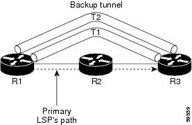
In this illustration, there are three routers: R1, R2, and R3. At R1 two NNHOP backup tunnels (T1 and T2) go from R1 to R3 without traversing R2.
Redundancy—If R2 fails or the link from R1 to R2 fails, either backup tunnel can be used. If one backup tunnel is down, the other can be used. LSPs are assigned to backup tunnels when the LSPs are first established. This is done before a failure.
Load balancing—If neither backup tunnel has enough bandwidth to back up all LSPs, both tunnels can be used. Some LSPs will use one backup tunnel, other LSPs will use the other backup tunnel. The router decides the best way to fit the LSPs onto the backup tunnels.
Backup Tunnel Selection Procedure
When an LSP is signaled, each node along the LSP path that provides FRR protection for the LSP selects a backup tunnel for the LSP to use if either of the following events occurs:
•![]() The link to the next hop fails.
The link to the next hop fails.
•![]() The next hop fails.
The next hop fails.
By having the node select the backup tunnel for an LSP before a failure occurs, the LSP can be rerouted onto the backup tunnel quickly if there is a failure.
For an LSP to be mapped to a backup tunnel, all of the following conditions must exist:
•![]() The LSP is protected by FRR; that is, the LSP is configured with the tunnel mpls traffic-eng fast-reroute command.
The LSP is protected by FRR; that is, the LSP is configured with the tunnel mpls traffic-eng fast-reroute command.
•![]() The backup tunnel is up.
The backup tunnel is up.
•![]() The backup tunnel is configured to have an IP address, typically a loopback address.
The backup tunnel is configured to have an IP address, typically a loopback address.
•![]() The backup tunnel is configured to protect this LSP's outgoing interface; that is, the interface is configured with the mpls traffic-eng backup-path command.
The backup tunnel is configured to protect this LSP's outgoing interface; that is, the interface is configured with the mpls traffic-eng backup-path command.
•![]() The backup tunnel does not traverse the LSP's protected interface.
The backup tunnel does not traverse the LSP's protected interface.
•![]() The backup tunnel terminates at the LSP's NHOP or NNHOP. If it is an NNHOP tunnel, it does not traverse the LSP's NHOP.
The backup tunnel terminates at the LSP's NHOP or NNHOP. If it is an NNHOP tunnel, it does not traverse the LSP's NHOP.
•![]() The bandwidth protection requirements and constraints, if any, for the LSP and backup tunnel are met. For information about bandwidth protection considerations, see the "Bandwidth Protection" section.
The bandwidth protection requirements and constraints, if any, for the LSP and backup tunnel are met. For information about bandwidth protection considerations, see the "Bandwidth Protection" section.
Bandwidth Protection
A backup tunnel can be configured to protect two types of backup bandwidth:
•![]() Limited backup bandwidth—A backup tunnel provides bandwidth protection. The sum of the bandwidth of all LSPs using this backup tunnel cannot exceed the backup tunnel's backup bandwidth. When you assign LSPs to this type of backup tunnel, sufficient backup bandwidth must exist.
Limited backup bandwidth—A backup tunnel provides bandwidth protection. The sum of the bandwidth of all LSPs using this backup tunnel cannot exceed the backup tunnel's backup bandwidth. When you assign LSPs to this type of backup tunnel, sufficient backup bandwidth must exist.
•![]() Unlimited backup bandwidth—The backup tunnel does not provide any bandwidth protection (that is, best-effort protection exists). There is no limit to the amount of bandwidth used by the LSPs that are mapped to this backup tunnel. LSPs that allocate zero bandwidth can use only backup tunnels that have unlimited backup bandwidth.
Unlimited backup bandwidth—The backup tunnel does not provide any bandwidth protection (that is, best-effort protection exists). There is no limit to the amount of bandwidth used by the LSPs that are mapped to this backup tunnel. LSPs that allocate zero bandwidth can use only backup tunnels that have unlimited backup bandwidth.
Load Balancing on Limited-Bandwidth Backup Tunnels
There may be more than one backup tunnel that has sufficient backup bandwidth to protect a given LSP. In this case, the router chooses the one that has the least amount of backup bandwidth available. This algorithm limits fragmentation, maintaining the largest amount of backup bandwidth available.
Specifying limited backup bandwidth does not "guarantee" bandwidth protection if there is a link or node failure. For example, the set of NHOP and NNHOP backup tunnels that gets triggered when an interface fails may all share some link on the network topology, and this link may not have sufficient bandwidth to support all LSPs using this set of backup tunnels.
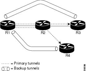
In Figure 5, both backup tunnels traverse the same links and hop. When the link between routers R1 and R4 fails, backup tunnels for primary tunnel 1 and primary tunnel 2 are triggered simultaneously. The two backup tunnels may share a link in the network.
Figure 5 Backup Tunnels Share a Link
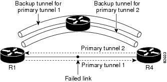
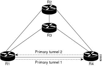
In Figure 6, the backup tunnel for primary tunnel 1 may traverse routers R1-R2-R3-R4, and the backup tunnel for primary tunnel 2 may traverse routers R4-R2-R3-R1. In this case, the link R2-R3 may get overloaded if R1-R4 fails.
Figure 6 Overloaded Link
Load Balancing on Unlimited-Bandwidth Backup Tunnels
More than one backup tunnel, each having unlimited backup bandwidth, can protect a given interface. In this case, when choosing a backup tunnel for a given LSP, the router chooses the backup tunnel that has the least amount of backup bandwidth in use. This algorithm evenly distributes the LSPs across backup tunnels based on an LSP's bandwidth. If an LSP is requesting zero bandwidth, the router chooses the backup tunnel that is protecting the fewest LSPs.
Pool Type and Backup Tunnels
By default, a backup tunnel provides protection for LSPs that allocate from any pool (that is, global or subpool). However, a backup tunnel can be configured to protect only LSPs that use global-pool bandwidth, or only those that use subpool bandwidth.
Tunnel Selection Priorities
This section describes the following:
•![]() NHOP Versus NNHOP Backup Tunnels
NHOP Versus NNHOP Backup Tunnels
•![]() Backup Protection Preemption Algorithms
Backup Protection Preemption Algorithms
NHOP Versus NNHOP Backup Tunnels
More than one backup tunnel can protect a given LSP, where one backup tunnel terminates at the LSP's NNHOP, and the other terminates at the LSP's NHOP. In this case, the router chooses the backup tunnel that terminates at the NNHOP (that is, FRR prefers NNHOP over NHOP backup tunnels).
Table 1 lists the tunnel selection priorities. The first choice is an NNHOP backup tunnel that acquires its bandwidth from a subpool or global pool, and has limited bandwidth. If there is no such backup tunnel, the next choice (2) is a next-next hop backup tunnel that acquires a limited amount of bandwidth from any pool. The preferences go from 1 (best) to 8 (worst), where choice 3 is for an NNHOP backup tunnel with an unlimited amount of subpool or global-pool bandwidth.
Figure 7 shows an example of the backup tunnel selection procedure based on the designated amount of global pool and subpool bandwidth currently available.

Note ![]() If NHOP and NNHOP backup tunnels do not have sufficient backup bandwidth, no consideration is given to the type of data that the LSP is carrying. For example, a voice LSP may not be protected unless it is signaled before a data LSP. To prioritize backup tunnel usage, see the "Backup Protection Preemption Algorithms" section.
If NHOP and NNHOP backup tunnels do not have sufficient backup bandwidth, no consideration is given to the type of data that the LSP is carrying. For example, a voice LSP may not be protected unless it is signaled before a data LSP. To prioritize backup tunnel usage, see the "Backup Protection Preemption Algorithms" section.
Figure 7 Choosing from Among Multiple Backup Tunnels
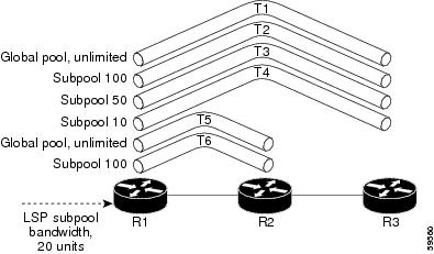
In this example, an LSP requires 20 units (kilobits per second) of sub-pool backup bandwidth. The best backup tunnel is selected as follows:
1. ![]() Backup tunnels T1 through T4 are considered first because they terminate at the NNHOP.
Backup tunnels T1 through T4 are considered first because they terminate at the NNHOP.
2. ![]() Tunnel T4 is eliminated because it has only ten units of sub-pool backup bandwidth.
Tunnel T4 is eliminated because it has only ten units of sub-pool backup bandwidth.
3. ![]() Tunnel T1 is eliminated because it protects only LSPs using global-pool bandwidth.
Tunnel T1 is eliminated because it protects only LSPs using global-pool bandwidth.
4. ![]() Tunnel T3 is chosen over T2 because, although both have sufficient backup bandwidth, T3 has the least backup bandwidth available (leaving the most backup bandwidth available on T2).
Tunnel T3 is chosen over T2 because, although both have sufficient backup bandwidth, T3 has the least backup bandwidth available (leaving the most backup bandwidth available on T2).
5. ![]() Tunnels T5 and T6 need not be considered because they terminate at an NHOP, and therefore are less desirable than T3, which terminates at an NNHOP.
Tunnels T5 and T6 need not be considered because they terminate at an NHOP, and therefore are less desirable than T3, which terminates at an NNHOP.
Promotion
After a backup tunnel has been chosen for an LSP, conditions may change that will cause us to reevaluate this choice. This reevaluation, if successful, is called promotion. Such conditions may include:
1. ![]() A new backup tunnel comes up.
A new backup tunnel comes up.
2. ![]() The currently chosen backup tunnel for this LSP goes down.
The currently chosen backup tunnel for this LSP goes down.
3. ![]() A backup tunnel's available backup bandwidth increases. For example, an LSP protected by the tunnel has been reoptimized by the headend to use another path.
A backup tunnel's available backup bandwidth increases. For example, an LSP protected by the tunnel has been reoptimized by the headend to use another path.
For cases 1 and 2, the LSP's backup tunnel is evaluated immediately. Case 3 is addressed by periodically reevaluating LSP-to-backup tunnel mappings. By default, background reevaluation is performed every 5 minutes. This interval is configurable via the mpls traffic-eng fast-reroute timers command.
Backup Protection Preemption Algorithms
When you set the "bandwidth protection desired" bit for an LSP, the LSP has a higher right to select backup tunnels that provide bandwidth protection and it can preempt other LSPs that do not have that bit set.
If there is insufficient backup bandwidth on NNHOP backup tunnels but not on NHOP backup tunnels, the bandwidth-protected LSP does not preempt NNHOP LSPs; it uses NHOP protection.
If there are multiple LSPs using a given backup tunnel and one or more must be demoted to provide bandwidth, there are two user-configurable methods (algorithms) that the router can use to determine which LSPs are demoted:
•![]() Minimize amount of bandwidth that is wasted.
Minimize amount of bandwidth that is wasted.
•![]() Minimize the number of LSPs that are demoted.
Minimize the number of LSPs that are demoted.
For example, If you need ten units of backup bandwidth on a backup tunnel, you can demote one of the following:
•![]() A single LSP using 100 units of bandwidth—Makes available more bandwidth than needed, but results in lots of waste
A single LSP using 100 units of bandwidth—Makes available more bandwidth than needed, but results in lots of waste
•![]() Ten LSPs, each using one unit of bandwidth—Results in no wasted bandwidth, but affects more LSPs
Ten LSPs, each using one unit of bandwidth—Results in no wasted bandwidth, but affects more LSPs
The default algorithm is to minimize the number of LSPs that are demoted. To change the algorithm to minimize the amount of bandwidth that is wasted, enter the mpls traffic-eng fast-reroute backup-prot-preemption optimize-bw command.
Bandwidth Protection Considerations
There are numerous ways in which bandwidth protection can be ensured. Table 2 describes the advantages and disadvantages of three methods.
Cisco implementation of FRR does not mandate a particular approach, and it provides the flexibility to use any of the above approaches. However, given a range of configuration choices, be sure that the choices are constant with a particular bandwidth protection strategy.
The following sections describe some important issues in choosing an appropriate configuration:
•![]() Using Backup Tunnels with Explicitly Signaled Bandwidth
Using Backup Tunnels with Explicitly Signaled Bandwidth
•![]() Using Backup Tunnels Signaled with Zero Bandwidth
Using Backup Tunnels Signaled with Zero Bandwidth
Using Backup Tunnels with Explicitly Signaled Bandwidth
Two bandwidth parameters must be set for a backup tunnel:
•![]() Actual signaled bandwidth
Actual signaled bandwidth
•![]() Backup bandwidth
Backup bandwidth
To signal bandwidth requirements of a backup tunnel, configure the bandwidth of the backup tunnel by using the tunnel mpls traffic-eng bandwidth command.
To configure the backup bandwidth of the backup tunnel, use the tunnel mpls traffic-eng backup-bw command.
The signaled bandwidth is used by the LSRs on the path of the backup tunnel to perform admission control and do appropriate bandwidth accounting.
The backup bandwidth is used by the point of local repair (PLR) (that is, the headend of the backup tunnel) to decide how much primary traffic can be rerouted to this backup tunnel if there is a failure.
Both parameters need to be set to ensure proper operation. The numerical value of the signaled bandwidth and the backup bandwidth should be the same.
Protected Bandwidth Pools and the Bandwidth Pool from Which the Backup Tunnel Reserves Its Bandwidth
The tunnel mpls traffic-eng bandwidth command allows you to configure the following:
•![]() Amount of bandwidth a backup tunnel reserves
Amount of bandwidth a backup tunnel reserves
•![]() The DS-TE bandwidth pool from which the bandwidth needs to be reserved
The DS-TE bandwidth pool from which the bandwidth needs to be reserved
Note ![]() Only one pool can be selected (that is, the backup tunnel can explicitly reserve bandwidth from either the global pool or the subpool, but not both).
Only one pool can be selected (that is, the backup tunnel can explicitly reserve bandwidth from either the global pool or the subpool, but not both).
The tunnel mpls traffic-eng backup-bw command allows you to specify the bandwidth pool to which the traffic must belong for the traffic to use this backup tunnel. Multiple pools are allowed.
There is no direct correspondence between the bandwidth pool that is protected and the bandwidth pool from which the bandwidth of the backup tunnel draws its bandwidth.
Bandwidth protection for 10 Kbps of subpool traffic on a given link can be achieved by configuring any of the following command combinations:
•![]() tunnel mpls traffic-eng bandwidth sub-pool 10
tunnel mpls traffic-eng bandwidth sub-pool 10
tunnel mpls traffic-eng backup-bw sub-pool 10
•![]() tunnel mpls traffic-eng bandwidth global-pool 10
tunnel mpls traffic-eng bandwidth global-pool 10
tunnel mpls traffic-eng backup-bw sub-pool 10 global-pool unlimited
•![]() tunnel mpls traffic-eng bandwidth global-pool 40
tunnel mpls traffic-eng bandwidth global-pool 40
tunnel mpls traffic-eng backup-bw sub-pool 10 global-pool 30
Using Backup Tunnels Signaled with Zero Bandwidth
Frequently it is desirable to use backup tunnels with zero signaled bandwidth, even when bandwidth protection is required. It may seem that if no bandwidth is explicitly reserved, no bandwidth guarantees can be provided. However, that is not necessarily true.
In the following situation:
•![]() Only link protection is desired.
Only link protection is desired.
•![]() Bandwidth protection is desired only for sub-pool traffic.
Bandwidth protection is desired only for sub-pool traffic.
For each protected link AB with a maximum reservable subpool value of n, there may be a path from node A to node B such that the difference between the maximum reservable global and the maximum reservable subpool is at least the value of n. If it is possible to find such paths for each link in the network, you can establish all the backup tunnels along such paths without any bandwidth reservations. If there is a single link failure, only one backup tunnel will use any link on its path. Because that path has at least n available bandwidth (in the global pool), assuming that marking and scheduling is configured to classify the subpool traffic into a priority queue, the subpool bandwidth is guaranteed.
This approach allows sharing of the global pool bandwidth between backup tunnels protecting independent link failures. The backup tunnels are expected to be used for only a short period of time after a failure (until the headends of affected LSPs reroute those LSPs to other paths with available subpool bandwidth). The probability of multiple unrelated link failures is very small (in the absence of node or shared risk link group (SRLG) failures, which result in multiple link failures). Therefore, it is reasonable to assume that link failures are in practice independent with high probability. This "independent failure assumption" in combination with backup tunnels signaled without explicit bandwidth reservation enables efficient bandwidth sharing that yields substantial bandwidth savings.
Backup tunnels protecting the subpool traffic do now draw bandwidth from any pool. Primary traffic using the global pool can use the entire global pool, and primary traffic using the subpool can use the entire subpool. Yet, subpool traffic has a complete bandwidth guarantee if there is a single link failure.
A similar approach can be used for node and SRLG protection. However, the decision of where to put the backup tunnels is more complicated because both node and SRLG failures effectively result in the simultaneous failure of several links. Therefore, the backup tunnels protecting traffic traversing all affected links cannot be computed independently of each other. The backup tunnels protecting groups of links corresponding to different failures can still be computed independently of each other, which results in similar bandwidth savings.
Signaled Bandwidth Versus Backup Bandwidth
Backup bandwidth is used locally (by the router that is the headend of the backup tunnel) to determine which, and how many, primary LSPs can be rerouted on a particular backup tunnel. The router ensures that the combined bandwidth requirement of these LSPs does not exceed the backup bandwidth.
Therefore, even when the backup tunnel is signaled with zero bandwidth, the backup bandwidth must be configured with the value corresponding to the actual bandwidth requirement of the traffic protected by this backup tunnel. Unlike the case when bandwidth requirements of the backup tunnels are explicitly signaled, the value of the signaled bandwidth (which is zero) is not the same value as the backup bandwidth.
How to Configure MPLS Traffic Engineering—Fast Reroute (FRR) Link and Node Protection
This section assumes that you want to add FRR protection to a network in which MPLS TE LSPs are configured.
This section contains the following procedures:
•![]() Enabling Fast Reroute on LSPs (required)
Enabling Fast Reroute on LSPs (required)
•![]() Creating a Backup Tunnel to the Next Hop or to the Next-Next Hop (required)
Creating a Backup Tunnel to the Next Hop or to the Next-Next Hop (required)
•![]() Assigning Backup Tunnels to a Protected Interface (required)
Assigning Backup Tunnels to a Protected Interface (required)
•![]() Associating Backup Bandwidth and Pool Type with a Backup Tunnel (optional)
Associating Backup Bandwidth and Pool Type with a Backup Tunnel (optional)
•![]() Configuring Backup Bandwidth Protection (optional)
Configuring Backup Bandwidth Protection (optional)
•![]() Configuring an Interface for Fast Link and Node Failure Detection (optional)
Configuring an Interface for Fast Link and Node Failure Detection (optional)
•![]() Verifying That Fast Reroute Is Operational (optional)
Verifying That Fast Reroute Is Operational (optional)
Enabling Fast Reroute on LSPs
LSPs can use backup tunnels only if they have been configured as fast reroutable. To do this, enter the following commands at the headend of each LSP.
SUMMARY STEPS
1. ![]() enable
enable
2. ![]() configure terminal
configure terminal
3. ![]() interface tunnel number
interface tunnel number
4. ![]() tunnel mpls traffic-eng fast-reroute [bw-protect]
tunnel mpls traffic-eng fast-reroute [bw-protect]
DETAILED STEPS
Creating a Backup Tunnel to the Next Hop or to the Next-Next Hop
Creating a backup tunnel is basically no different from creating any other tunnel. To create a backup tunnel to the next hop or to the next-next hop, enter the following commands on the node that will be the headend of the backup tunnel (that is, the node whose downstream link or node may fail). The node on which you enter these commands must be a supported platform. See the "Finding Feature Information" section.
SUMMARY STEPS
1. ![]() enable
enable
2. ![]() configure terminal
configure terminal
3. ![]() interface tunnel number
interface tunnel number
4. ![]() ip unnumbered interface-type interface-number
ip unnumbered interface-type interface-number
5. ![]() tunnel destination ip-address
tunnel destination ip-address
6. ![]() tunnel mode mpls traffic-eng
tunnel mode mpls traffic-eng
7. ![]() tunnel mpls traffic-eng path-option [protect] number {dynamic | explicit | {name path-name | path-number}} [lockdown]
tunnel mpls traffic-eng path-option [protect] number {dynamic | explicit | {name path-name | path-number}} [lockdown]
8. ![]() ip explicit-path name word
ip explicit-path name word
9. ![]() exclude-address ip-address
exclude-address ip-address
DETAILED STEPS
Assigning Backup Tunnels to a Protected Interface
To assign one or more backup tunnels to a protected interface, enter the following commands on the node that will be the headend of the backup tunnel (that is, the node whose downstream link or node may fail). The node on which you enter these commands must be a supported platform. See the "Finding Feature Information" section.
Note ![]() You must configure the interface to have an IP address and to enable the MPLS TE tunnel feature.
You must configure the interface to have an IP address and to enable the MPLS TE tunnel feature.
SUMMARY STEPS
1. ![]() enable
enable
2. ![]() configure terminal
configure terminal
3. ![]() interface type slot/port
interface type slot/port
4. ![]() mpls traffic-eng backup-path tunnel interface
mpls traffic-eng backup-path tunnel interface
DETAILED STEPS
|
|
|
|
|---|---|---|
Step 1 |
enable Router> enable |
Enables privileged EXEC mode. • |
Step 2 |
configure terminal Router# configure terminal |
Enters global configuration mode. |
Step 3 |
interface type slot/port
Router(config)# interface POS 5/0 |
Moves configuration to the physical interface level, directing subsequent configuration commands to the specific physical interface identified by the type value. The slot and port identify the slot and port being configured. The interface must be a supported interface. See the "Finding Feature Information" section. Enters interface configuration mode. |
Step 4 |
mpls traffic-eng backup-path tunnel interface Router(config-if)# mpls traffic-eng backup-path tunnel 2 |
Allows LSPs going out this interface to use this backup tunnel if there is a link or node failure. Note |
Associating Backup Bandwidth and Pool Type with a Backup Tunnel
To associate backup bandwidth with a backup tunnel and designate the type of LSP that can use a backup tunnel, enter the following commands.
SUMMARY STEPS
1. ![]() enable
enable
2. ![]() configure terminal
configure terminal
3. ![]() interface tunnel number
interface tunnel number
4. ![]() tunnel mpls traffic-eng backup-bw {bandwidth | [sub-pool {bandwidth | Unlimited}] [global-pool {bandwidth | Unlimited}]
tunnel mpls traffic-eng backup-bw {bandwidth | [sub-pool {bandwidth | Unlimited}] [global-pool {bandwidth | Unlimited}]
DETAILED STEPS
Configuring Backup Bandwidth Protection
SUMMARY STEPS
1. ![]() enable
enable
2. ![]() configure terminal
configure terminal
3. ![]() tunnel mpls traffic-eng-fast-reroute [bw-protect]
tunnel mpls traffic-eng-fast-reroute [bw-protect]
4. ![]() mpls traffic-eng fast-reroute backup-prot-preemption [optimize-bw]
mpls traffic-eng fast-reroute backup-prot-preemption [optimize-bw]
DETAILED STEPS
Configuring an Interface for Fast Link and Node Failure Detection
SUMMARY STEPS
1. ![]() enable
enable
2. ![]() configure terminal
configure terminal
3. ![]() interface type slot/port
interface type slot/port
4. ![]() pos ais-shut
pos ais-shut
5. ![]() pos report {b1-tca | b2-tca | b3-tca | lais | lrdi | pais | plop | prdi | rdool | sd-ber | sf-ber | slof | slos}
pos report {b1-tca | b2-tca | b3-tca | lais | lrdi | pais | plop | prdi | rdool | sd-ber | sf-ber | slof | slos}
DETAILED STEPS
Verifying That Fast Reroute Is Operational
SUMMARY STEPS
Note ![]() To determine if FRR has been configured correctly, perform Steps 1 and 2.
To determine if FRR has been configured correctly, perform Steps 1 and 2.
Note ![]() If you created LSPs and performed the required configuration tasks but do not have operational backup tunnels (that is, the backup tunnels are not up or the LSPs are not associated with those backup tunnels), perform Step 3.
If you created LSPs and performed the required configuration tasks but do not have operational backup tunnels (that is, the backup tunnels are not up or the LSPs are not associated with those backup tunnels), perform Step 3.
1. ![]() show mpls traffic-eng tunnels brief
show mpls traffic-eng tunnels brief
2. ![]() show ip rsvp sender detail
show ip rsvp sender detail
3. ![]() show mpls traffic-eng fast-reroute database
show mpls traffic-eng fast-reroute database
4. ![]() show mpls traffic-eng tunnels backup
show mpls traffic-eng tunnels backup
5. ![]() show mpls traffic-eng fast-reroute database
show mpls traffic-eng fast-reroute database
6. ![]() show ip rsvp reservation
show ip rsvp reservation
DETAILED STEPS
Step 1 ![]() show mpls traffic-eng tunnels brief
show mpls traffic-eng tunnels brief
Use this command to verify that backup tunnels are up:
Router# show mpls traffic-eng tunnels brief
Following is sample output from the show mpls traffic-eng tunnels brief command:
Signalling Summary:
LSP Tunnels Process: running
RSVP Process: running
Forwarding: enabled
Periodic reoptimization: every 3600 seconds, next in 1706 seconds
TUNNEL NAME DESTINATION UP IF DOWN IF STATE/PROT
Router_t1 10.112.0.12 - PO4/0/1 up/up
Router_t2 10.112.0.12 - unknown up/down
Router_t3 10.112.0.12 - unknown admin-down
Router_t1000 10.110.0.10 - unknown up/down
Router_t2000 10.110.0.10 - PO4/0/1 up/up
Displayed 5 (of 5) heads, 0 (of 0) midpoints, 0 (of 0) tails
Step 2 ![]() show ip rsvp sender detail
show ip rsvp sender detail
Use this command to verify that LSPs are protected by the appropriate backup tunnels.
Following is sample output from the show ip rsvp sender detail command when the command is entered at the PLR before a failure.
Router# show ip rsvp sender detail
PATH:
Tun Dest: 10.10.0.6 Tun ID: 100 Ext Tun ID: 10.10.0.1
Tun Sender: 10.10.0.1 LSP ID: 31
Path refreshes:
arriving: from PHOP 10.10.7.1 on Et0/0 every 30000 msecs
Session Attr:
Setup Prio: 7, Holding Prio: 7
Flags: (0x7) Local Prot desired, Label Recording, SE Style
session Name: R1_t100
ERO: (incoming)
10.10.7.2 (Strict IPv4 Prefix, 8 bytes, /32)
10.10.0.6 (Strict IPv4 Prefix, 8 bytes, /32)
RRO:
10.10.7.1/32, Flags:0x0 (No Local Protection)
10.10.4.1/32, Flags:0x9 (Local Prot Avail/to NNHOP) !Available to NNHOP
10.10.1.1/32, Flags:0x0 (No Local Protection)
Traffic params - Rate: 10K bits/sec, Max. burst: 1K bytes
Min Policed Unit: 0 bytes, Max Pkt Size 4294967295 bytes
Fast-Reroute Backup info:
Inbound FRR: Not active
Outbound FRR: No backup tunnel selected
Path ID handle: 50000416.
Incoming policy: Accepted. Policy source(s): MPLS/TE
Status: Proxy-terminated
Step 3 ![]() show mpls traffic-eng fast-reroute database
show mpls traffic-eng fast-reroute database
Enter the clear ip rsvp hello instance counters command to verify the following:
•![]() MPLS TE FRR node protection has been enabled.
MPLS TE FRR node protection has been enabled.
•![]() A certain type of LSP can use a backup tunnel.
A certain type of LSP can use a backup tunnel.
The following command output displays the LSPs that are protected:
Router# show mpls traffic-eng fast-reroute database
Tunnel head end item frr information:
Protected Tunnel In-label intf/label FRR intf/label Status
Tunne1l0 Tun pos5/0:Untagged Tu0:12304 ready
Prefix item frr information:
Prefix Tunnel In-label Out intf/label FRR intf/label Status
10.0.0.11/32 Tu110 Tun hd pos5/0:Untagged Tu0:12304 ready
LSP midpoint frr information:
LSP identifier In-label Out intf/label FRR intf/label Status
10.0.0.12 1 [459] 16 pos0/1:17 Tu2000:19 ready
If LDP is not enabled, separate prefix items are not shown because all prefixes then use a single rewrite. To confirm that a particular IP prefix is FRR protected, even though it is not shown in this display, enter it within the show mpls forwarding-table ip-address detail command. The final line of the display will tell whether that prefix is protected:
Router# show mpls forwarding-table 10.0.0.11 detail
Local Outgoing Prefix Bytes tag Outgoing Next Hop
tag tag or VC or Tunnel Id switched interface
Tun hd Untagged 10.0.0.11/32 48 pos5/0 point2point
MAC/Encaps=4/8, MTU=1520, Tag Stack{22}
48D18847 00016000
No output feature configured
Fast Reroute Protection via (Tu0, outgoing label 12304)
Step 4 ![]() show mpls traffic-eng tunnels backup
show mpls traffic-eng tunnels backup
For backup tunnels to be operational, the LSP must be reroutable. At the headend of the LSP, enter the show run int tunnel tunnel-number command. The output should include the tunnel mpls traffic-eng fast-reroute command. If it does not, enter this command for the tunnel.
On the router where the backup tunnels originate, enter the show mpls traffic-eng tunnels backup command. Following is sample command output:
Router# show mpls traffic-eng tunnels backup
Router_t578
LSP Head, Tunnel578, Admin: up, Oper: up
Src 10.55.55.55, Dest 10.88.88.88, Instance 1
Fast Reroute Backup Provided:
Protected i/fs: PO1/0, PO1/1, PO3/3
Protected lsps: 1
Backup BW: any pool unlimited; inuse: 100 kbps
Router_t5710
LSP Head, Tunnel5710, Admin: admin-down, Oper: down
Src 10.55.55.55, Dest 10.7.7.7, Instance 0
Fast Reroute Backup Provided:
Protected i/fs: PO1/1
Protected lsps: 0
Backup BW: any pool unlimited; inuse: 0 kbps
Router_t5711
  LSP Head, Tunnel5711, Admin up, Oper: up
  Src 10.55.55.55,, Dest 10.7.7.7, Instance 1
Fast Reroute Backup Provided:
Protected i/fs: PO1/0
Protected lsps: 2
Backup BW: any pool unlimited; inuse: 6010 kbps
The command output will allow you to verify the following:
•![]() Backup tunnel exists—Verify that there is a backup tunnel that terminates at this LSP's NHOP or NNHOP. Look for the LSP's NHOP or NNHOP in the Dest field.
Backup tunnel exists—Verify that there is a backup tunnel that terminates at this LSP's NHOP or NNHOP. Look for the LSP's NHOP or NNHOP in the Dest field.
•![]() Backup tunnel is up—To verify that the backup tunnel is up, look for "Up" in the State field.
Backup tunnel is up—To verify that the backup tunnel is up, look for "Up" in the State field.
•![]() Backup tunnel is associated with LSP's interface—Verify that the interface for the LSP is allowed to use this backup tunnel. Look for the LSP's output interface in the "protects" field list.
Backup tunnel is associated with LSP's interface—Verify that the interface for the LSP is allowed to use this backup tunnel. Look for the LSP's output interface in the "protects" field list.
•![]() Backup tunnel has sufficient bandwidth—If you restricted the amount of bandwidth a backup tunnel can hold, verify that the backup tunnel has sufficient bandwidth to hold the LSPs that would use this backup tunnel if there is a failure. The bandwidth of an LSP is defined by the line tunnel mpls traffic-eng bandwidth at the headend of the LSP. To determine the available bandwidth on a backup tunnel, look at the "cfg" and "inuse" fields. If there is insufficient backup bandwidth to accommodate the LSPs that would use this backup tunnel in the event of a failure, create an additional backup tunnel or increase the backup bandwidth of the existing tunnel by using the tunnel mpls traffic-eng bandwidth command.
Backup tunnel has sufficient bandwidth—If you restricted the amount of bandwidth a backup tunnel can hold, verify that the backup tunnel has sufficient bandwidth to hold the LSPs that would use this backup tunnel if there is a failure. The bandwidth of an LSP is defined by the line tunnel mpls traffic-eng bandwidth at the headend of the LSP. To determine the available bandwidth on a backup tunnel, look at the "cfg" and "inuse" fields. If there is insufficient backup bandwidth to accommodate the LSPs that would use this backup tunnel in the event of a failure, create an additional backup tunnel or increase the backup bandwidth of the existing tunnel by using the tunnel mpls traffic-eng bandwidth command.
Note ![]() To determine the sufficient amount of bandwidth, offline capacity planning may be required.
To determine the sufficient amount of bandwidth, offline capacity planning may be required.
•![]() Backup tunnel has appropriate bandwidth type—If you restricted the type of LSPs (subpool or global pool) that can use this backup tunnel, verify that the LSP is the appropriate type for the backup tunnel. The type of the LSP is defined by the line tunnel mpls traffic-eng bandwidth at the headend of this LSP. If this line contains the word "subpool", then it uses sub-pool bandwidth; otherwise, it uses global pool bandwidth. Verify that the type matches the type the backup tunnel can hold by looking in the output of the tunnel mpls traffic-eng bandwidth command.
Backup tunnel has appropriate bandwidth type—If you restricted the type of LSPs (subpool or global pool) that can use this backup tunnel, verify that the LSP is the appropriate type for the backup tunnel. The type of the LSP is defined by the line tunnel mpls traffic-eng bandwidth at the headend of this LSP. If this line contains the word "subpool", then it uses sub-pool bandwidth; otherwise, it uses global pool bandwidth. Verify that the type matches the type the backup tunnel can hold by looking in the output of the tunnel mpls traffic-eng bandwidth command.
You also can enable debug by entering the debug ip rsvp fast-reroute command and the debug mpls traffic-eng fast-reroute command on the router that is the headend of the backup tunnel. Then do the following:
1. ![]() Enter the shutdown command for the primary tunnel.
Enter the shutdown command for the primary tunnel.
2. ![]() Enter the no shutdown command for the primary tunnel.
Enter the no shutdown command for the primary tunnel.
3. ![]() View the debug output.
View the debug output.
Step 5 ![]() show mpls traffic-eng fast-reroute database
show mpls traffic-eng fast-reroute database
Enter the clear ip rsvp hello instance counters command to verify the following:
•![]() MPLS TE FRR node protection has been enabled.
MPLS TE FRR node protection has been enabled.
•![]() A certain type of LSP can use a backup tunnel.
A certain type of LSP can use a backup tunnel.
The following command output displays the LSPs that are protected:
Router# show mpls traffic-eng fast-reroute database
Tunnel head end item frr information:
Protected Tunnel In-label intf/label FRR intf/label Status
Tunne1l0 Tun pos5/0:Untagged Tu0:12304 ready
Prefix item frr information:
Prefix Tunnel In-label Out intf/label FRR intf/label Status
10.0.0.11/32 Tu110 Tun hd pos5/0:Untagged Tu0:12304 ready
LSP midpoint frr information:
LSP identifier In-label Out intf/label FRR intf/label Status
10.0.0.12 1 [459] 16 pos0/1:17 Tu2000:19 ready
Note ![]() If LDP is not enabled, separate prefix items are not shown because all prefixes then use a single rewrite. To confirm that a particular IP prefix is FRR protected, even though it is not shown in this display, enter it within the show mpls forwarding-table ip-address detail command. The final line of the display will tell whether that prefix is protected:
If LDP is not enabled, separate prefix items are not shown because all prefixes then use a single rewrite. To confirm that a particular IP prefix is FRR protected, even though it is not shown in this display, enter it within the show mpls forwarding-table ip-address detail command. The final line of the display will tell whether that prefix is protected:
Router# show mpls forwarding-table 10.0.0.11 detail
Local Outgoing Prefix Bytes tag Outgoing Next Hop
tag tag or VC or Tunnel Id switched interface
Tun hd Untagged 10.0.0.11/32 48 pos5/0 point2point
MAC/Encaps=4/8, MTU=1520, Tag Stack{22}
48D18847 00016000
No output feature configured
Fast Reroute Protection via (Tu0, outgoing label 12304)
Step 6 ![]() show ip rsvp reservation
show ip rsvp reservation
Following is sample output from the show ip rsvp reservation command entered at the headend of a primary LSP. Entering the command at the headend of the primary LSP shows, among other things, the status of FRR (that is, local protection) at each hop this LSP traverses. The per-hop information is collected in the Record Route Object (RRO) that travels with the Resv message from the tail to the head.
Router# show ip rsvp reservation detail
Reservation:
Tun Dest: 10.1.1.1 Tun ID: 1 Ext Tun ID: 172.16.1.1
Tun Sender: 172.16.1.1 LSP ID: 104
Next Hop: 172.17.1.2 on POS1/0
Label: 18 (outgoing)
Reservation Style is Shared-Explicit, QoS Service is Controlled-Load
Average Bitrate is 0 bits/sec, Maximum Burst is 1K bytes
Min Policed Unit: 0 bytes, Max Pkt Size: 0 bytes
RRO:
172.18.1.1/32, Flags:0x1 (Local Prot Avail/to NHOP)
Label subobject: Flags 0x1, C-Type 1, Label 18
172.19.1.1/32, Flags:0x0 (Local Prot Avail/In Use/Has BW/to NHOP)
Label subobject: Flags 0x1, C-Type 1, Label 16
172.19.1.2/32, Flags:0x0 (No Local Protection)
Label subobject: Flags 0x1, C-Type 1, Label 0
Resv ID handle: CD000404.
Policy: Accepted. Policy source(s): MPLS/TE
Notice the following about the primary LSP:
•![]() It has protection that uses a NHOP backup tunnel at its first hop.
It has protection that uses a NHOP backup tunnel at its first hop.
•![]() It has protection and is actively using an NHOP backup tunnel at its second hop.
It has protection and is actively using an NHOP backup tunnel at its second hop.
•![]() It has no local protection at its third hop.
It has no local protection at its third hop.
The RRO display shows the following information for each hop:
•![]() Whether local protection is available (that is, whether the LSP has selected a backup tunnel)
Whether local protection is available (that is, whether the LSP has selected a backup tunnel)
•![]() Whether local protection is in use (that is, whether the LSP is currently using its selected backup tunnel)
Whether local protection is in use (that is, whether the LSP is currently using its selected backup tunnel)
•![]() Whether the selected backup tunnel is an NHOP or NNHOP backup tunnel
Whether the selected backup tunnel is an NHOP or NNHOP backup tunnel
•![]() Whether the backup tunnel used at this hop provides bandwidth protection
Whether the backup tunnel used at this hop provides bandwidth protection
Troubleshooting Tips
This section describes the following:
•![]() LSPs Do Not Become Active; They Remain Ready
LSPs Do Not Become Active; They Remain Ready
•![]() Primary Tunnel Does Not Select Backup Tunnel That Is Up
Primary Tunnel Does Not Select Backup Tunnel That Is Up
•![]() Enhanced RSVP Commands Display Useful Information
Enhanced RSVP Commands Display Useful Information
•![]() RSVP Hello Detects When a Neighboring Node Is Not Reachable
RSVP Hello Detects When a Neighboring Node Is Not Reachable
•![]() Hello Instances Have Not Been Created
Hello Instances Have Not Been Created
LSPs Do Not Become Active; They Remain Ready
At a PLR, LSPs transition from Ready to Active if one of the following events occurs:
•![]() Primary interface goes down—If the primary interface (LSP's outbound interface) goes down and the LSP is ready to use a backup tunnel, the LSP will transition to the active state causing its data to flow over the backup tunnel. On some platforms and interface types (for example, GSR POS interfaces), there is fast interface-down logic that detects this event very quickly. On other platforms where this logic does not exist, detection time is slower. On such platforms, it may be desirable to enable RSVP Hello (see the next bulleted item, "Hellos detect next hop is down").
Primary interface goes down—If the primary interface (LSP's outbound interface) goes down and the LSP is ready to use a backup tunnel, the LSP will transition to the active state causing its data to flow over the backup tunnel. On some platforms and interface types (for example, GSR POS interfaces), there is fast interface-down logic that detects this event very quickly. On other platforms where this logic does not exist, detection time is slower. On such platforms, it may be desirable to enable RSVP Hello (see the next bulleted item, "Hellos detect next hop is down").
•![]() Hellos detect next hop is down—If Hellos are enabled on the primary interface (LSP's outbound interface), and the LSP's next hop is no longer reachable, the next hop is declared down. This event will cause the LSP to begin actively using its backup tunnel. Notice that a next hop will be declared down even if the primary interface does not go down. For example, if the next hop stops responding due to a reboot or software orr hardware problem, Hellos will trigger the LSPs using this next hop to switch to their backup tunnels. Hellos can also help trigger FRR on interfaces such as Gigabit Ethernet where the interface remains up but is unusable (due to lack of link-layer liveness detection mechanisms).
Hellos detect next hop is down—If Hellos are enabled on the primary interface (LSP's outbound interface), and the LSP's next hop is no longer reachable, the next hop is declared down. This event will cause the LSP to begin actively using its backup tunnel. Notice that a next hop will be declared down even if the primary interface does not go down. For example, if the next hop stops responding due to a reboot or software orr hardware problem, Hellos will trigger the LSPs using this next hop to switch to their backup tunnels. Hellos can also help trigger FRR on interfaces such as Gigabit Ethernet where the interface remains up but is unusable (due to lack of link-layer liveness detection mechanisms).
Primary Tunnel Does Not Select Backup Tunnel That Is Up
If a backup tunnel is up, but it is not selected as a backup tunnel by the primary tunnel (LSP), enter the following commands for the backup tunnel:
•![]() shutdown
shutdown
•![]() no shutdown
no shutdown
Note ![]() If you change the status of a backup tunnel, the backup tunnel selection algorithm is rerun for the backup tunnel. LSPs that have currently selected (that is, are ready to use) that backup tunnel will be disassociated from it, and then reassociated with that backup tunnel or another backup tunnel. This is generally harmless and usually results in mapping the same LSPs to that backup tunnel. However, if any LSPs are actively using that backup tunnel, shutting down the backup tunnel will tear down those LSPs.
If you change the status of a backup tunnel, the backup tunnel selection algorithm is rerun for the backup tunnel. LSPs that have currently selected (that is, are ready to use) that backup tunnel will be disassociated from it, and then reassociated with that backup tunnel or another backup tunnel. This is generally harmless and usually results in mapping the same LSPs to that backup tunnel. However, if any LSPs are actively using that backup tunnel, shutting down the backup tunnel will tear down those LSPs.
Enhanced RSVP Commands Display Useful Information
The following RSVP commands have been enhanced to display information that can be helpful when you are examining the FRR state or troubleshooting FRR:
•![]() show ip rsvp request—Displays upstream reservation state (that is, information related to the Resv messages that this node will send upstream).
show ip rsvp request—Displays upstream reservation state (that is, information related to the Resv messages that this node will send upstream).
•![]() show ip rsvp reservation—Displays information about Resv messages received.
show ip rsvp reservation—Displays information about Resv messages received.
•![]() show ip rsvp sender—Displays information about path messages being received.
show ip rsvp sender—Displays information about path messages being received.
These commands show control plane state; they do not show data state. That is, they show information about RSVP messages (Path and Resv) used to signal LSPs. For information about the data packets being forwarded along LSPs, use the show mpls forwarding command.
RSVP Hello Detects When a Neighboring Node Is Not Reachable
The RSVP Hello feature enables RSVP nodes to detect when a neighboring node is not reachable. Use this feature when notification of link-layer failures is not available and unnumbered links are not used, or when the failure detection mechanisms provided by the link layer are not sufficient for timely node failure detection. Hello must be configured both globally on the router and on the specific interface to be operational.
Hello Instances Have Not Been Created
If Hello instances have not been created, do the following:
•![]() Determine if RSVP Hello has been enabled globally on the router. Enter the ip rsvp signalling hello (configuration) command.
Determine if RSVP Hello has been enabled globally on the router. Enter the ip rsvp signalling hello (configuration) command.
•![]() Determine if RSVP Hello has been enabled on an interface that the LSPs traverse. Enter the ip rsvp signalling hello (interface) command.
Determine if RSVP Hello has been enabled on an interface that the LSPs traverse. Enter the ip rsvp signalling hello (interface) command.
•![]() Verify that at least one LSP has a backup tunnel by displaying the output of the show ip rsvp sender command. A value of "Ready" indicates that a backup tunnel has been selected.
Verify that at least one LSP has a backup tunnel by displaying the output of the show ip rsvp sender command. A value of "Ready" indicates that a backup tunnel has been selected.
"No entry at index" (error may self-correct, RRO may not yet have propagated from downstream node of interest)" Error Message Is Printed at the Point of Local Repair
FRR relies on a RRO in Resv messages arriving from downstream. Routers receiving path messages with the SESSION_ATTRIBUTE bit indicating that the LSP is fast-reroutable should include an RRO in the corresponding Resv messages.
If an LSP is configured for FRR, but the Resv arriving from a downstream router contains an incomplete RRO, the "No entry at index (error may self-correct, RRO may not yet have propagated from downstream node of interest)" message is printed. An incomplete RRO is one in which the NHOP or the NNHOP did not include an entry in the RRO.
This error typically means that backup tunnels to the NHOP or the NNHOP cannot be selected for this LSP because there is insufficient information about the NHOP or NNHOP due to the lack of an RRO entry.
Occasionally there are valid circumstances in which this situation occurs temporarily and the problem is self-corrected. If subsequent Resv messages arrive with a complete RRO, ignore the error message.
To determine whether the error has been corrected, display the RRO in Resv messages by entering the clear ip rsvp hello instance counters command. Use an output filter keyword to display only the LSP of interest.
"Couldn't get rsbs" (error may self-correct when Resv arrives)" Error Message Is Printed at the Point of Local Repair
The PLR cannot select a backup tunnel for an LSP until a Resv message has arrived from downstream.
When this error occurs, it typically means that something is wrong. For example, no reservation exists for this LSP. You can troubleshoot this problem by using the debug ip rsvp reservation command to enable debug.
Occasionally there are valid circumstances in which this error message occurs and there is no need for concern. One such circumstance is when an LSP experiences a change before any Resv message has arrived from downstream. Changes can cause a PLR to try to select a backup tunnel for an LSP, and the selection will fail (causing this error message) if no Resv message has arrived for this LSP.
Configuration Examples for MPLS Traffic Engineering—Fast Reroute (FRR) Link and Node Protection
This section provides the following configuration examples:
•![]() Enabling Fast Reroute for all Tunnels: Example
Enabling Fast Reroute for all Tunnels: Example
•![]() Creating an NHOP Backup Tunnel: Example
Creating an NHOP Backup Tunnel: Example
•![]() Creating an NNHOP Backup Tunnel: Example
Creating an NNHOP Backup Tunnel: Example
•![]() Assigning Backup Tunnels to a Protected Interface: Example
Assigning Backup Tunnels to a Protected Interface: Example
•![]() Associating Backup Bandwidth and Pool Type with Backup Tunnels: Example
Associating Backup Bandwidth and Pool Type with Backup Tunnels: Example
•![]() Configuring Backup Bandwidth Protection: Example
Configuring Backup Bandwidth Protection: Example
•![]() Configuring an Interface for Fast Link and Node Failure Detection: Example
Configuring an Interface for Fast Link and Node Failure Detection: Example
•![]() Configuring RSVP Hello and POS Signals: Example
Configuring RSVP Hello and POS Signals: Example
The examples relate to the illustration shown in Figure 8.
Figure 8 Backup Tunnels
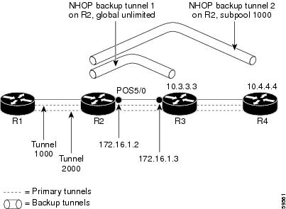
Enabling Fast Reroute for all Tunnels: Example
On router R1, enter interface configuration mode for each tunnel to be protected (Tunnel 1000 and Tunnel 2000). Enable these tunnels to use a backup tunnel in case of a link or node failure along their paths.
Tunnel 1000 will use 10 units of bandwidth from the subpool.
Tunnel 2000 will use five units of bandwidth from the global pool. The "bandwidth protection desired" bit has been set by specifying bw-prot in the tunnel mpls traffic-eng fast-reroute command.
Router(config)# interface Tunnel 1000
Router(config-if)# tunnel mpls traffic-eng fast-reroute
Router(config-if)# tunnel mpls traffic-eng bandwidth sub-pool 10
Router(config)# interface Tunnel2000
Router(config-if)# tunnel mpls traffic-eng fast-reroute bw-prot
Router(config-if)# tunnel mpls traffic-eng bandwidth 5
Creating an NHOP Backup Tunnel: Example
On router R2, create an NHOP backup tunnel to R3. This backup tunnel should avoid using the link 172.1.1.2.
Router(config)# ip explicit-path name avoid-protected-link
Router(cfg-ip-expl-path)# exclude-address 172.1.1.2
Explicit Path name avoid-protected-link:
____1: exclude-address 172.1.1.2
Router(cfg-ip_expl-path)# end
Router(config)# interface Tunnel 1
Router(config-if)# ip unnumbered loopback0
Router(config-if)# tunnel destination 10.3.3.3
Router(config-if)# tunnel mode mpls traffic-eng
Router(config-if)# tunnel mpls traffic-eng path-option 10 explicit avoid-protected-link
Creating an NNHOP Backup Tunnel: Example
On router R2, create an NNHOP backup tunnel to R4. This backup tunnel should avoid R3.
Router(config)# ip explicit-path name avoid-protected-node
Router(cfg-ip-expl-path)# exclude-address 10.3.3.3
Explicit Path name avoid-protected-node:
____1: exclude-address 10.3.3.3
Router(cfg-ip_expl-path)# end
Router(config)# interface Tunnel 2
Router(config-if)# ip unnumbered loopback0
Router(config-if)# tunnel destination 10.4.4.4
Router(config-if)# tunnel mode mpls traffic-eng
Router(config-if)# tunnel mpls traffic-eng path-option 10 explicit avoid-protected-node
Assigning Backup Tunnels to a Protected Interface: Example
On router R2, associate both backup tunnels with interface POS 5/0:
Router(config)# interface POS 5/0
Router(config-if)# mpls traffic-eng backup-path tunnel 1
Router(config-if)# mpls traffic-eng backup-path tunnel 2
Associating Backup Bandwidth and Pool Type with Backup Tunnels: Example
Backup tunnel 1 is to be used only by LSPs that take their bandwidth from the global pool. It does not provide bandwidth protection. Backup tunnel 2 is to be used only by LSPs that take their bandwidth from the subpool. Backup tunnel 2 provides bandwidth protection for up to 1000 units.
Router(config)# interface Tunnel 1
Router(config-if)# tunnel mpls traffic-eng backup-bw global-pool Unlimited
Router(config)# interface Tunnel 2
Router(config-if)# tunnel mpls traffic-eng backup-bw sub-pool 1000
Configuring Backup Bandwidth Protection: Example
In the following example, backup bandwidth protection is configured:
Note ![]() This global configuration is required only to change the backup protection preemption algorithm from minimize the number of LSPs that are demoted to minimize the amount of bandwidth that is wasted.
This global configuration is required only to change the backup protection preemption algorithm from minimize the number of LSPs that are demoted to minimize the amount of bandwidth that is wasted.
Router(config-if)# tunnel mpls traffic-eng fast-reroute bw-protect
Router(config)# mpls traffic-eng fast-reroute backup-prot-preemption optimize-bw
Configuring an Interface for Fast Link and Node Failure Detection: Example
In the following example, pos ais-shut is configured:
Router(config)# interface pos 0/0
Router(config-if)# pos ais-shut
In the following example, report lrdi is configured on OS interfaces:
Router(config)# interface pos 0/0
Router(config-if)# pos report lrdi
Configuring RSVP Hello and POS Signals: Example
Hello must be configured both globally on the router and on the specific interface on which you need FRR protection. To configure Hello, use the following configuration commands:
•![]() ip rsvp signalling hello (configuration)—Enables Hello globally on the router.
ip rsvp signalling hello (configuration)—Enables Hello globally on the router.
•![]() ip rsvp signalling hello (interface)—Enables Hello on an interface where you need FRR protection.
ip rsvp signalling hello (interface)—Enables Hello on an interface where you need FRR protection.
The following configuration commands are optional:
•![]() ip rsvp signalling hello dscp—Sets the differentiated services code point (DSCP) value that is in the IP header of the Hello message.
ip rsvp signalling hello dscp—Sets the differentiated services code point (DSCP) value that is in the IP header of the Hello message.
•![]() ip rsvp signalling hello refresh misses—Specifies how many acknowledgments a node can miss in a row before the node considers that communication with its neighbor is down.
ip rsvp signalling hello refresh misses—Specifies how many acknowledgments a node can miss in a row before the node considers that communication with its neighbor is down.
•![]() ip rsvp signalling hello refresh interval—Configures the Hello request interval.
ip rsvp signalling hello refresh interval—Configures the Hello request interval.
•![]() ip rsvp signalling hello statistics—Enables Hello statistics on the router.
ip rsvp signalling hello statistics—Enables Hello statistics on the router.
For configuration examples, see the Hello command descriptions in the "Command Reference" section of MPLS Traffic Engineering (TE): Link and Node Protection, with RSVP Hellos Support, Release 12.0(24)S.
To configure POS signaling for detecting FRR failures, enter the pos report all command or enter the following commands to request individual reports:
pos ais-shut
pos report rdool
pos report lais
pos report lrdi
pos report pais
pos report prdi
pos report sd-ber
Additional References
Related Documents
|
|
|
|---|---|
IS-IS |
Cisco IOS IP Routing Protocols Command Reference |
Link protection |
|
Shared risk link groups |
MPLS Traffic Engineering: Shared Risk Link Groups |
FRR protection of TE LSPs from SRLG failure |
|
MPLS traffic engineering commands |
|
Configuration of MPLS TE tunnels |
|
OSPF |
Cisco IOS IP Routing Protocols Command Reference |
RSVP |
Standards
|
|
|
|---|---|
draft-ietf-mpls-rsvp-lsp-fastreroute-04.txt |
MIBs
RFCs
|
|
|
|---|---|
draft-ietf-mpls-rsvp-lsp-fastreroute-06.txt |
Technical Assistance
Command Reference
The following commands are introduced or modified in the feature or features documented in this module. For information about these commands, see the Cisco IOS Multiprotocol Label Switching Command Reference at http://www.cisco.com/en/US/docs/ios/mpls/command/reference/mp_book.html. For information about all Cisco IOS commands, use the Command Lookup Tool at http://tools.cisco.com/Support/CLILookup or the Cisco IOS Master Command List, All Releases, at http://www.cisco.com/en/US/docs/ios/mcl/allreleasemcl/all_book.html.
•![]() clear ip rsvp hello instance counters
clear ip rsvp hello instance counters
•![]() clear ip rsvp hello instance statistics
clear ip rsvp hello instance statistics
•![]() clear ip rsvp hello statistics
clear ip rsvp hello statistics
•![]() debug ip rsvp hello
debug ip rsvp hello
•![]() ip rsvp signalling hello (configuration)
ip rsvp signalling hello (configuration)
•![]() ip rsvp signalling hello (interface)
ip rsvp signalling hello (interface)
•![]() ip rsvp signalling hello dscp
ip rsvp signalling hello dscp
•![]() ip rsvp signalling hello refresh interval
ip rsvp signalling hello refresh interval
•![]() ip rsvp signalling hello refresh misses
ip rsvp signalling hello refresh misses
•![]() ip rsvp signalling hello statistics
ip rsvp signalling hello statistics
•![]() mpls traffic-eng backup-path tunnel
mpls traffic-eng backup-path tunnel
•![]() mpls traffic-eng fast-reroute backup-prot-preemption
mpls traffic-eng fast-reroute backup-prot-preemption
•![]() mpls traffic-eng fast-reroute timers
mpls traffic-eng fast-reroute timers
•![]() show ip rsvp fast bw-protect
show ip rsvp fast bw-protect
•![]() show ip rsvp fast detail
show ip rsvp fast detail
•![]() show ip rsvp hello
show ip rsvp hello
•![]() show ip rsvp hello instance detail
show ip rsvp hello instance detail
•![]() show ip rsvp hello instance summary
show ip rsvp hello instance summary
•![]() show ip rsvp hello statistics
show ip rsvp hello statistics
•![]() show ip rsvp interface detail
show ip rsvp interface detail
•![]() show ip rsvp request
show ip rsvp request
•![]() show ip rsvp reservation
show ip rsvp reservation
•![]() show ip rsvp sender
show ip rsvp sender
•![]() show mpls traffic tunnel backup
show mpls traffic tunnel backup
•![]() show mpls traffic-eng fast-reroute database
show mpls traffic-eng fast-reroute database
•![]() show mpls traffic-eng tunnels
show mpls traffic-eng tunnels
•![]() show mpls traffic-eng tunnels summary
show mpls traffic-eng tunnels summary
•![]() tunnel mpls traffic-eng backup-bw
tunnel mpls traffic-eng backup-bw
•![]() tunnel mpls traffic-eng fast-reroute
tunnel mpls traffic-eng fast-reroute
Feature Information for MPLS Traffic Engineering—Fast Reroute Link and Node Protection
Table 3 lists the release history for this feature.
Not all commands may be available in your Cisco IOS software release. For release information about a specific command, see the command reference documentation.
Use Cisco Feature Navigator to find information about platform support and software image support. Cisco Feature Navigator enables you to determine which Cisco IOS and Catalyst OS software images support a specific software release, feature set, or platform. To access Cisco Feature Navigator, go to http://www.cisco.com/go/cfn. An account on Cisco.com is not required.
Note ![]() Table 3 lists only the Cisco IOS software release that introduced support for a given feature in a given Cisco IOS software release train. Unless noted otherwise, subsequent releases of that Cisco IOS software release train also support that feature.
Table 3 lists only the Cisco IOS software release that introduced support for a given feature in a given Cisco IOS software release train. Unless noted otherwise, subsequent releases of that Cisco IOS software release train also support that feature.
Glossary
backup bandwidth—The usage of NHOP and NNHOP backup tunnels to provide bandwidth protection for rerouted LSPs.
backup tunnel—An MPLS TE tunnel used to protect other (primary) tunnels' traffic when a link or node failure occurs.
bandwidth—The available traffic capacity of a link.
Cisco Express Forwarding—A means for accelerating the forwarding of packets within a router, by storing route lookup.
enterprise network—A large and diverse network connecting most major points in a company or other organization.
Fast Reroute—Procedures that enable temporary routing around a failed link or node while a new LSP is being established at the headend.
global pool—The total bandwidth allocated to an MPLS traffic engineering link or node.
headend—The router that originates and maintains a given LSP. This is the first router in the LSP's path.
hop—Passage of a data packet between two network nodes (for example, between two routers).
instance—A Hello instance implements the RSVP Hello extensions for a given router interface address and remote IP address. Active Hello instances periodically send Hello Request messages, expecting Hello ACK messages in response. If the expected ACK message is not received, the active Hello instance declares that the neighbor (remote IP address) is unreachable (that is, it is lost). This can cause LSPs crossing this neighbor to be fast rerouted.
interface—A network connection.
Intermediate System-to-Intermediate System—IS-IS. Link-state hierarchical routing protocol that calls for intermediate system (IS) routers to exchange routing information based on a single metric to determine network topology.
link—A point-to-point connection between adjacent nodes. There can be more than one link between adjacent nodes. A link is a network communications channel consisting of a circuit or transmission path and all related equipment between a sender and a receiver. Sometimes referred to as a line or a transmission link.
limited backup bandwidth—Backup tunnels that provide bandwidth protection.
load balancing—A configuration technique that shifts traffic to an alternative link if a certain threshold is exceeded on the primary link. Load balancing is similar to redundancy in that if an event causes traffic to shift directions, alternative equipment must be present in the configuration. In load balancing, the alternative equipment is not necessarily redundant equipment that operates only in the event of a failure.
LSP—label-switched path. A connection between two routers in which MPLS forwards the packets.
merge point—The backup tunnel's tail.
MPLS—Multiprotocol Label Switching. Packet-forwarding technology, used in the network core, that applies data link layer labels to tell switching nodes how to forward data, resulting in faster and more scalable forwarding than network layer routing normally can do.
MPLS global label allocation—There is one label space for all interfaces in the router. For example, label 100 coming in one interface is treated the same as label 100 coming in a different interface.
NHOP—next hop. The next downstream node along an LSP's path.
NHOP backup tunnel—next-hop backup tunnel. Backup tunnel terminating at the LSP's next hop beyond the point of failure, and originating at the hop immediately upstream of the point of failure. It bypasses a failed link, and is used to protect primary LSPs that were using this link before the failure.
NNHOP—next-next hop. The node after the next downstream node along an LSP's path.
NNHOP backup tunnel—next-next-hop backup tunnel. Backup tunnel terminating at the LSP's next-next hop beyond the point of failure, and originating at the hop immediately upstream of the point of failure. It bypasses a failed link or node, and is used to protect primary LSPs that were using this link or node before the failure.
node—Endpoint of a network connection or a junction common to two or more lines in a network. Nodes can be interconnected by links, and serve as control points in the network. Nodes can be processors, controllers, or workstations.
OSPF—Open Shortest Path First. A link-state hierarchical Interior Gateway Protocol routing algorithm, derived from the IS-IS protocol. OSPF features include least-cost routing, multipath routing, and load balancing.
primary LSP—The last LSP originally signaled over the protected interface before the failure. The primary LSP is the LSP before the failure.
primary tunnel—Tunnel whose LSP may be fast rerouted if there is a failure. Backup tunnels cannot be primary tunnels.
promotion—Conditions, such as a new backup tunnel comes up, cause a reevaluation of a backup tunnel that was chosen for an LSP. If the reevaluation is successful, it is called a promotion.
protected interface—An interface that has one or more backup tunnels associated with it.
redundancy—The duplication of devices, services, or connections so that, in the event of a failure, the redundant devices, services, or connections can perform the work of those that failed.
RSVP—Resource Reservation Protocol. A protocol used for signaling requests (setting up reservations) for Internet services by a customer before that customer is permitted to transmit data over that portion of the network.
scalability—An indicator showing how quickly some measure of resource usage increases as a network gets larger.
SRLG—shared risk link group. Sets of links that are likely to go down together.
state—Information that a router must maintain about each LSP. The information is used for rerouting tunnels.
sub-pool—The more restrictive bandwidth in an MPLS traffic engineering link or node. The subpool is a portion of the link or node's overall global pool bandwidth.
tailend—The router upon which an LSP is terminated. This is the last router in the LSP's path.
topology—The physical arrangement of network nodes and media within an enterprise networking structure.
tunnel—Secure communications path between two peers, such as two routers.
unlimited backup bandwidth—Backup tunnels that provide no bandwidth (best-effort) protection (that is, they provide best-effort protection).
 Feedback