-
- MPLS Traffic Engineering - LSP Attributes
- MPLS Traffic Engineering (TE) - Autotunnel Primary and Backup
- MPLS Traffic Engineering - AutoTunnel Mesh Groups
- MPLS Traffic Engineering - Verbatim Path Support
- MPLS Traffic Engineering - RSVP Hello State Timer
- MPLS Traffic Engineering Forwarding Adjacency
- MPLS Traffic Engineering (TE) - Class-based Tunnel Selection
- MPLS Traffic Engineering - Interarea Tunnels
- MPLS TE - Bundled Interface Support
- MPLS Traffic Engineering�Automatic Bandwidth Adjustment for TE Tunnels
- MPLS Point-to-Multipoint Traffic Engineering
- MPLS Traffic Engineering�Tunnel Source
-
- MPLS Traffic Engineering - Inter-AS TE
- MPLS Traffic Engineering - Shared Risk Link Groups
- MPLS Traffic Engineering (TE) - Autotunnel Primary and Backup
- MPLS Traffic Engineering (TE) - Path Protection
- MPLS Traffic Engineering (TE) - Fast Reroute (FRR) Link and Node Protection
- MPLS TE: Link and Node Protection, with RSVP Hellos Support (with Fast Tunnel Interface Down Detection)
- MPLS Traffic Engineering: BFD-triggered Fast Reroute (FRR)
-
- MPLS MTU Command Changes
- AToM Static Pseudowire Provisioning
- MPLS Pseudowire Status Signaling
- L2VPN Interworking
- L2VPN Pseudowire Redundancy
- L2VPN Pseudowire Switching
- VPLS Autodiscovery: BGP Based
- H-VPLS N-PE Redundancy for QinQ and MPLS Access
- L2VPN Multisegment Pseudowires
- QOS Policy Support on L2VPN ATM PVPs
- L2VPN: Pseudowire Preferential Forwarding
-
- Configuring MPLS Layer 3 VPNs
- MPLS VPN Half-Duplex VRF
- MPLS VPN�Show Running VRF
- MPLS VPN�VRF CLI for IPv4 and IPv6 VPNs
- MPLS VPN--BGP Local Convergence
- MPLS VPN�Route Target Rewrite
- MPLS VPN�Per VRF Label
- MPLS VPN 6VPE per VRF Label
- MPLS Multi-VRF (VRF Lite) Support
- BGP Best External
- BGP PIC Edge for IP and MPLS-VPN
- MPLS VPN - L3VPN over GRE
- Dynamic Layer-3 VPNs with Multipoint GRE Tunnels
- MPLS VPN over mGRE
-
- MPLS LSP Ping/Traceroute for LDP/TE, and LSP Ping for VCCV
- MPLS EM�MPLS LSP Multipath Tree Trace
- Pseudowire Emulation Edge-to-Edge MIBs for Ethernet, Frame Relay, and ATM Services
- MPLS Enhancements to Interfaces MIB
- MPLS Label Distribution Protocol MIB Version 8 Upgrade
- MPLS EM�MPLS LDP MIB - RFC 3815
- MPLS Label Switching Router MIB
- MPLS EM�MPLS LSR MIB - RFC 3813
- MPLS Traffic Engineering MIB
- MPLS Traffic Engineering - Fast Reroute MIB
- MPLS EM - TE MIB RFC 3812
- MPLS VPN�MIB Support
- MPLS EM - MPLS VPN MIB RFC4382 Upgrade
-
- MPLS High Availability: Overview
- MPLS High Availability: Command Changes
- MPLS LDP Graceful Restart
- NSF/SSO - MPLS LDP and LDP Graceful Restart
- NSF/SSO: MPLS VPN
- AToM Graceful Restart
- NSF/SSO�Any Transport over MPLS and AToM Graceful Restart
- NSF/SSO - MPLS TE and RSVP Graceful Restart
- ISSU MPLS Clients
- NSF/SSO/ISSU Support for VPLS
- NSF/SSO and ISSU - MPLS VPN 6VPE and 6PE
Cisco IOS Multiprotocol Label Switching Configuration Guide, Release 12.2SR
Bias-Free Language
The documentation set for this product strives to use bias-free language. For the purposes of this documentation set, bias-free is defined as language that does not imply discrimination based on age, disability, gender, racial identity, ethnic identity, sexual orientation, socioeconomic status, and intersectionality. Exceptions may be present in the documentation due to language that is hardcoded in the user interfaces of the product software, language used based on RFP documentation, or language that is used by a referenced third-party product. Learn more about how Cisco is using Inclusive Language.
- Updated:
- February 12, 2008
Chapter: MPLS EM—MPLS LSR MIB - RFC 3813
- Contents
- Prerequisites for MPLS EM—MPLS LSR MIB - RFC 3813
- Restrictions for MPLS EM—MPLS LSR MIB - RFC 3813
- Information About MPLS EM—MPLS LSR MIB - RFC 3813
- MPLS-LSR-STD-MIB Benefits
- Label Switching Information Managed by the MPLS-LSR-STD-MIB
- MPLS-LSR-STD-MIB Elements
- Brief Description of MPLS-LSR-STD-MIB Tables
- MPLS LSR Information Available Through the MPLS-LSR-STD-MIB
- MPLS Interface Table (mplsInterfaceTable)
- MPLS Interface Performance Table (mplsInterfacePerfTable)
- MPLS In-Segment Table (mplsInSegmentTable)
- MPLS In-Segment Performance Table (mplsInSegmentPerfTable)
- MPLS Out-Segment Table (mplsOutSegmentTable)
- MPLS Out-Segment Performance Table (mplsOutSegmentPerfTable)
- MPLS Cross-Connect Table (mplsXCTable)
- MPLS Label Stack Table (mplsLabelStackTable)
- MPLS In-Segment Map Table (mplsInSegmentMapTable)
- Information from MPLS-LSR-STD-MIB Scalar Objects
- MPLS-LSR-STD-MIB Indexing—Linking Table Elements
- Interface Configuration Table and Interface MIB Links
- MPLS-LSR-STD-MIB Structure
- CLI Commands and the MPLS-LSR-MIB
- VPN Aware LSR MIB
- Major Differences Between the MPLS-LSR-STD-MIB and the MPLS-LSR-MIB
MPLS EM—MPLS LSR MIB - RFC 3813
The MPLS LSR MIB- RFC 3813 (MPLS-LSR-STD-MIB) allows you to use the Simple Network Management Protocol (SNMP) to remotely monitor a label switch router (LSR) that is using the Multiprotocol Label Switching (MPLS) technology.
This document describes the MPLS-LSR-STD-MIB. The document also describes the major differences between the MPLS-LSR-STD-MIB and draft Version 5 of the MPLS-LSR-MIB.
The MPLS EM—MPLS LSR MIB - RFC 3813 feature introduces the MPLS-LSR-STD-MIB, which is an upgrade from draft Version 5 of the MPLS-LSR-MIB to an implementation of the Multiprotocol Label Switching (MPLS) Label Switching Router (LSR) Management Information Base (MIB), RFC 3813. This feature also introduces the VPN Aware LSR MIB feature that enables the MPLS-LSR-STD-MIB to get VPN context information.
Cisco IOS MPLS Embedded Management (EM) is a set of standards and value-added services that facilitate the deployment, operation, administration, and management of MPLS-based networks in line with the fault, configuration, accounting, performance, and security (FCAPS) model.
Finding Feature Information in This Module
Your Cisco IOS software release may not support all of the features documented in this module. For the latest feature information and caveats, see the release notes for your platform and software release. To reach links to specific feature documentation in this module and to see a list of the releases in which each feature is supported, use the "Feature Information for MPLS EM—MPLS LSR MIB - RFC 3813" section.
Finding Support Information for Platforms and Cisco IOS and Catalyst OS Software Images
Use Cisco Feature Navigator to find information about platform support and Cisco IOS and Catalyst OS software image support. To access Cisco Feature Navigator, go to http://www.cisco.com/go/cfn. An account on Cisco.com is not required.
Contents
•![]() Prerequisites for MPLS EM—MPLS LSR MIB - RFC 3813
Prerequisites for MPLS EM—MPLS LSR MIB - RFC 3813
•![]() Information About MPLS EM—MPLS LSR MIB - RFC 3813
Information About MPLS EM—MPLS LSR MIB - RFC 3813
•![]() How to Configure SNMP for the MPLS EM—MPLS LSR MIB - RFC 3813
How to Configure SNMP for the MPLS EM—MPLS LSR MIB - RFC 3813
•![]() Configuration Examples for the MPLS EM—MPLS LSR MIB - RFC 3813
Configuration Examples for the MPLS EM—MPLS LSR MIB - RFC 3813
•![]() Feature Information for MPLS EM—MPLS LSR MIB - RFC 3813
Feature Information for MPLS EM—MPLS LSR MIB - RFC 3813
•![]() Feature Information for MPLS EM—MPLS LSR MIB - RFC 3813
Feature Information for MPLS EM—MPLS LSR MIB - RFC 3813
Prerequisites for MPLS EM—MPLS LSR MIB - RFC 3813
The MPLS-LSR-STD-MIB requires the following:
•![]() SNMP installed and enabled on the LSR
SNMP installed and enabled on the LSR
•![]() MPLS enabled on the LSR
MPLS enabled on the LSR
•![]() MPLS Forwarding Infrastructure (MFI)
MPLS Forwarding Infrastructure (MFI)
Restrictions for MPLS EM—MPLS LSR MIB - RFC 3813
•![]() The implementation of the MPLS-LSR-STD-MIB (RFC 3815) for Cisco IOS Releases 12.2(33)SRB and 12.2(33)SB is limited to read-only (RO) permission for MIB objects.
The implementation of the MPLS-LSR-STD-MIB (RFC 3815) for Cisco IOS Releases 12.2(33)SRB and 12.2(33)SB is limited to read-only (RO) permission for MIB objects.
•![]() The following MIB objects are not supported in Cisco IOS Releases 12.2(33)SRB and 12.2(33)SB:
The following MIB objects are not supported in Cisco IOS Releases 12.2(33)SRB and 12.2(33)SB:
–![]() mplsInterfaceTotalBandwidth (MPLS interface table)
mplsInterfaceTotalBandwidth (MPLS interface table)
–![]() mplsInterfaceAvailableBandwidth (MPLS interface table)
mplsInterfaceAvailableBandwidth (MPLS interface table)
–![]() mplsInterfacePerfInLabelLookupFailures (MPLS interface performance table)
mplsInterfacePerfInLabelLookupFailures (MPLS interface performance table)
–![]() mplsInterfacePerfOutFragmentedPkts (MPLS interface performance table)
mplsInterfacePerfOutFragmentedPkts (MPLS interface performance table)
–![]() mplsInSegmentTrafficParamPtr (MPLS in-segment table)
mplsInSegmentTrafficParamPtr (MPLS in-segment table)
–![]() mplsInSegmentPerfDiscards (MPLS in-segment performance table)
mplsInSegmentPerfDiscards (MPLS in-segment performance table)
•![]() The following notifications are not supported:
The following notifications are not supported:
–![]() mplsXCUp
mplsXCUp
–![]() mplsXCDown
mplsXCDown
Information About MPLS EM—MPLS LSR MIB - RFC 3813
Before you configure SNMP and the MPLS-LSR-STD-MIB to remotely manage an MPLS LSR, you should understand the following concepts:
•![]() Label Switching Information Managed by the MPLS-LSR-STD-MIB
Label Switching Information Managed by the MPLS-LSR-STD-MIB
•![]() Brief Description of MPLS-LSR-STD-MIB Tables
Brief Description of MPLS-LSR-STD-MIB Tables
•![]() MPLS LSR Information Available Through the MPLS-LSR-STD-MIB
MPLS LSR Information Available Through the MPLS-LSR-STD-MIB
•![]() Information from MPLS-LSR-STD-MIB Scalar Objects
Information from MPLS-LSR-STD-MIB Scalar Objects
•![]() MPLS-LSR-STD-MIB Indexing—Linking Table Elements
MPLS-LSR-STD-MIB Indexing—Linking Table Elements
•![]() Interface Configuration Table and Interface MIB Links
Interface Configuration Table and Interface MIB Links
•![]() CLI Commands and the MPLS-LSR-MIB
CLI Commands and the MPLS-LSR-MIB
•![]() Major Differences Between the MPLS-LSR-STD-MIB and the MPLS-LSR-MIB
Major Differences Between the MPLS-LSR-STD-MIB and the MPLS-LSR-MIB
MPLS-LSR-STD-MIB Benefits
The benefits described in the following paragraphs are available to you with the MPLS-LSR-STD-MIB.
LSR Problem Troubleshooting
By monitoring the cross-connect entries and the associated incoming and outgoing segments, you can see which labels are installed and how they are being swapped. Use the MPLS-LSR-STD-MIB in place of the show mpls forwarding command-line interface (CLI) command.
LSR Traffic Load Monitoring
By monitoring interface and packet operations on an MPLS LSR, you can identify high- and low-traffic patterns, and traffic distributions.
Improvement of Network Performance
By identifying potentially high-traffic areas, you can set up load sharing to improve network performance.
Verification of LSR Configuration
By comparing results from SNMP get commands and the show mpls forwarding CLI command, you can verify your LSR configuration.
Active Label Switched Paths Monitoring
By monitoring the cross-connect entries and the associated incoming segments and outgoing segments, you can determine the active LSPs.
Label Switching Information Managed by the MPLS-LSR-STD-MIB
The MPLS-LSR-STD-MIB contains managed objects that support the retrieval of label switching information from a router. The MIB is based on RFC 3813. This implementation enables a network administrator to get information on the status, character, and performance of the following:
•![]() MPLS-capable interfaces on the LSR
MPLS-capable interfaces on the LSR
•![]() Incoming MPLS segments (labels) at an LSR and their associated parameters
Incoming MPLS segments (labels) at an LSR and their associated parameters
•![]() Outgoing segments (labels) at an LSR and their associated parameters
Outgoing segments (labels) at an LSR and their associated parameters
In addition, the network administrator can retrieve the status of cross-connect table entries that associate MPLS segments with each other.
Figure 1 shows the association of the cross-connect table with incoming and outgoing segments (labels).
Figure 1 Label Forwarding with the Cross-Connect Table
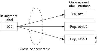

Note ![]() The out-segment table does not display "no label" entries. Labels that are displayed as "POP" are the special MPLS label 3.
The out-segment table does not display "no label" entries. Labels that are displayed as "POP" are the special MPLS label 3.
The notation used in the MPLS-LSR-STD-MIB follows the conventions defined in Abstract System Notation One (ASN.1). ASN.1 defines an Open Systems Interconnection (OSI) language used to describe data types independently from particular computer structures and presentation techniques. Each object in the MIB incorporates a DESCRIPTION field that includes an explanation of the object's meaning and usage, which, together with the other characteristics of the object (SYNTAX, MAX-ACCESS, and INDEX) provides sufficient information for management application development, as well as for documentation and testing.
The MPLS-LSR-STD-MIB represents an ASN.1 notation that represents an idealized MPLS LSR.
A network administrator can access the entries (objects) in the MPLS-LSR-STD-MIB by means of any SNMP-based network management system (NMS). The network administrator can retrieve information in the MPLS-LSR-STD-MIB using standard SNMP get and getnext commands.
Typically, SNMP runs as a low-priority process. The response time for the MPLS-LSR-STD-MIB is expected to be similar to that for other MIBs. The size and structure of the MIB and other MIBs in the system influence response time when you retrieve information from the management database. Traffic through the LSR also affects SNMP performance. The busier the switch is with forwarding activities, the greater the possibility of lower SNMP performance.
MPLS-LSR-STD-MIB Elements
The top-level components of the MPLS-LSR-STD-MIB are:
•![]() Tables and scalars (mplsLsrObjects)
Tables and scalars (mplsLsrObjects)
•![]() Notifications (mplsLsrNotifications)
Notifications (mplsLsrNotifications)
•![]() Conformance (mplsLsrConformance)
Conformance (mplsLsrConformance)
Brief Description of MPLS-LSR-STD-MIB Tables
This section lists and briefly describes of the main and supplementary tables in the MPLS-LSR-STD-MIB.
The Cisco implementation of the MPLS-LSR-STD-MIB supports four main tables:
•![]() MPLS interface table (mplsInterfaceTable)—Contains entries for all MPLS-capable interfaces on the LSR.
MPLS interface table (mplsInterfaceTable)—Contains entries for all MPLS-capable interfaces on the LSR.
•![]() MPLS in-segment table (mplsInSegmentTable)—Contains a description of incoming labels on the LSR.
MPLS in-segment table (mplsInSegmentTable)—Contains a description of incoming labels on the LSR.
•![]() Mpls out-segment table (mplsOutSegmentTable)—Contains a description of outgoing labels on the LSR.
Mpls out-segment table (mplsOutSegmentTable)—Contains a description of outgoing labels on the LSR.
•![]() MPLS cross-connect table (mplsXCTable)—Contains the connections between the in-segments and out-segments on the LSR. A single cross-connect entry is equivalent to a single entry in the Label Forwarding Information Base (LFIB), showing an in-label being switched to an out-label. A cross-connect entry can exist where no corresponding in-segment exists. For example, only the outgoing label exists at the head end of a traffic engineering (TE) tunnel.
MPLS cross-connect table (mplsXCTable)—Contains the connections between the in-segments and out-segments on the LSR. A single cross-connect entry is equivalent to a single entry in the Label Forwarding Information Base (LFIB), showing an in-label being switched to an out-label. A cross-connect entry can exist where no corresponding in-segment exists. For example, only the outgoing label exists at the head end of a traffic engineering (TE) tunnel.
Three tables manage labels, the MPLS in-segment table, the MPLS out-segment table, and the MPLS cross-connect tables.
The MIB contains three supplementary tables to supply performance information:
•![]() MPLS interface performance table (mplsInterfacePerfTable)—Augments the MPLS interface table. Provides objects to measure performance for MPLS-capable interfaces on the LSR.
MPLS interface performance table (mplsInterfacePerfTable)—Augments the MPLS interface table. Provides objects to measure performance for MPLS-capable interfaces on the LSR.
•![]() MPLS in-segment performance table (mplsInSegmentPerfTable)—Augments the MPLS in-segment table. Provides performance information and counters for incoming segments on the LSR.
MPLS in-segment performance table (mplsInSegmentPerfTable)—Augments the MPLS in-segment table. Provides performance information and counters for incoming segments on the LSR.
•![]() MPLS out-segment performance table (mplsOutSegmentPerfTable)—Augments the MPLS out-segment table. Provides performance information and counters for outgoing segments on the LSR.
MPLS out-segment performance table (mplsOutSegmentPerfTable)—Augments the MPLS out-segment table. Provides performance information and counters for outgoing segments on the LSR.
MPLS LSR Information Available Through the MPLS-LSR-STD-MIB
You can use SNMP get and getnext commands to gather label switching information for an MPLS LSR available through the MPLS-LSR-STD-MIB tables. This section describes the MPLS LSR information available from each table:
•![]() MPLS Interface Table (mplsInterfaceTable)
MPLS Interface Table (mplsInterfaceTable)
•![]() MPLS Interface Performance Table (mplsInterfacePerfTable)
MPLS Interface Performance Table (mplsInterfacePerfTable)
•![]() MPLS In-Segment Table (mplsInSegmentTable)
MPLS In-Segment Table (mplsInSegmentTable)
•![]() MPLS In-Segment Performance Table (mplsInSegmentPerfTable)
MPLS In-Segment Performance Table (mplsInSegmentPerfTable)
•![]() MPLS Out-Segment Table (mplsOutSegmentTable)
MPLS Out-Segment Table (mplsOutSegmentTable)
•![]() MPLS Out-Segment Performance Table (mplsOutSegmentPerfTable)
MPLS Out-Segment Performance Table (mplsOutSegmentPerfTable)
•![]() MPLS Cross-Connect Table (mplsXCTable)
MPLS Cross-Connect Table (mplsXCTable)
•![]() MPLS Label Stack Table (mplsLabelStackTable)
MPLS Label Stack Table (mplsLabelStackTable)
•![]() MPLS In-Segment Map Table (mplsInSegmentMapTable)
MPLS In-Segment Map Table (mplsInSegmentMapTable)
MPLS Interface Table (mplsInterfaceTable)
Table 1 lists the MPLS LSR information and associated MIB objects provided by the MPLS interface table (mplsInterfaceTable).
The following MIB objects and associated MPLS LSR information from the MPLS interface table are not supported:
•![]() mplsInterfaceTotalBandwidth—The total usable bandwidth on the interface.
mplsInterfaceTotalBandwidth—The total usable bandwidth on the interface.
•![]() mplsInterfaceAvailableBandwidth—The difference between the total usable bandwidth and the bandwidth in use.
mplsInterfaceAvailableBandwidth—The difference between the total usable bandwidth and the bandwidth in use.
MPLS Interface Performance Table (mplsInterfacePerfTable)
Table 2 lists the MPLS LSR information and associated MIB objects provided by the MPLS interface performance table (mplsInterfacePerfTable).
The following MIB objects and associated MPLS LSR information from the MPLS interface performance table are not supported:
•![]() mplsInterfacePerfInLabelLookupFailures—The number of labeled packets discarded because no cross-connect entries exist.
mplsInterfacePerfInLabelLookupFailures—The number of labeled packets discarded because no cross-connect entries exist.
•![]() mplsInterfacePerfOutFragmentedPkts—The number of outgoing MPLS packets requiring fragmentation for transmission.
mplsInterfacePerfOutFragmentedPkts—The number of outgoing MPLS packets requiring fragmentation for transmission.
MPLS In-Segment Table (mplsInSegmentTable)
Table 3 lists the MPLS LSR information and associated MIB objects provided by the MPLS in-segment table (mplsInSegmentTable).
The following MIB object and associated MPLS LSR information from the MPLS in-segment table is not supported:
•![]() mplsInSegmentTrafficParamPtr—A pointer to a traffic parameter table entry (set to the default 0.0).
mplsInSegmentTrafficParamPtr—A pointer to a traffic parameter table entry (set to the default 0.0).
MPLS In-Segment Performance Table (mplsInSegmentPerfTable)
Table 4 lists the MPLS LSR information and associated MIB objects provided by the MPLS in-segment performance table (mplsInSegmentPerfTable).
The following MIB object and associated MPLS LSR information from the MPLS in-segment performance table is not supported:
•![]() mplsInSegmentPerfDiscards—The number of labeled packets discarded with no errors.
mplsInSegmentPerfDiscards—The number of labeled packets discarded with no errors.
MPLS Out-Segment Table (mplsOutSegmentTable)
Table 5 lists the MPLS LSR information and associated MIB objects provided by the MPLS out-segment table (mplsOutSegmentTable).
The following MIB object and associated MPLS LSR information from the8—A pointer to a traffic parameter table entry (set to the default 0.0).
MPLS Out-Segment Performance Table (mplsOutSegmentPerfTable)
Table 6 lists the MPLS LSR information and associated MIB objects provided by the MPLS out-segment performance table (mplsOutSegmentPerfTable).
The following MIB object and associated MPLS LSR information from the MPLS out-segment performance table is not supported:
•![]() mplsOutSegmentPerfDiscards—The number of packets discarded with no errors.
mplsOutSegmentPerfDiscards—The number of packets discarded with no errors.
MPLS Cross-Connect Table (mplsXCTable)
Table 7 lists the MPLS LSR information and associated MIB objects provided by the MPLS cross-connect table (mplsXCTable).
Note ![]() The administrative status and operational status are always up in the Cisco implementation. Otherwise, these status entries do not appear in the table.
The administrative status and operational status are always up in the Cisco implementation. Otherwise, these status entries do not appear in the table.
MPLS Label Stack Table (mplsLabelStackTable)
Table 8 lists the MPLS LSR information and associated MIB objects provided by the MPLS label stack table (mplsLabelStackTable).
MPLS In-Segment Map Table (mplsInSegmentMapTable)
Table 9 lists the MPLS LSR information and associated MIB objects provided by the MPLS in-segment map table.
Information from MPLS-LSR-STD-MIB Scalar Objects
The MPLS-LSR-STD-MIB supports several scalar objects. In the Cisco implementation of the MIB for Cisco IOS Releases 12.2(33)SRB and 12.2(33(SB), the following scalar objects are hard-coded to the value indicated and are read-only objects. This symbol (" ") indicates an empty string.
•![]() mplsInSegmentIndexNext (" ")—The value for the in-segment index when the LSR creates an entry in the MPLS in-segment table. The " " indicates that this is not implemented because modifications to this table are not allowed.
mplsInSegmentIndexNext (" ")—The value for the in-segment index when the LSR creates an entry in the MPLS in-segment table. The " " indicates that this is not implemented because modifications to this table are not allowed.
•![]() mplsOutSegmentIndexNext (" ")—The value for the out-segment index when an LSR creates a new entry in the MPLS out-segment table. The " " indicates that this is not implemented because modifications to this table are not allowed.
mplsOutSegmentIndexNext (" ")—The value for the out-segment index when an LSR creates a new entry in the MPLS out-segment table. The " " indicates that this is not implemented because modifications to this table are not allowed.
•![]() mplsXCTIndexNext (" ")—The value for the cross-connect index when an LSR creates an entry in the MPLS cross-connect table. The " " indicates that no unassigned values are available.
mplsXCTIndexNext (" ")—The value for the cross-connect index when an LSR creates an entry in the MPLS cross-connect table. The " " indicates that no unassigned values are available.
•![]() mplsMaxLabelStackDepth (6)—The value for the maximum stack depth.
mplsMaxLabelStackDepth (6)—The value for the maximum stack depth.
•![]() mplsLabelStackIndexNext (" ")—The value for the label stack index when an LSR creates entries in the MPLS label stack table. The " " indicates that no unassigned values are available.
mplsLabelStackIndexNext (" ")—The value for the label stack index when an LSR creates entries in the MPLS label stack table. The " " indicates that no unassigned values are available.
•![]() mplsXCNotificationEnable (false)—Cross-connect notifications are not sent when this value is false.
mplsXCNotificationEnable (false)—Cross-connect notifications are not sent when this value is false.
The following notifications are not supported:
•![]() mplsXCUp
mplsXCUp
•![]() mplsXCDown
mplsXCDown
MPLS-LSR-STD-MIB Indexing—Linking Table Elements
In the MPLS cross-connect table, cross-connect entries associate incoming segments with outgoing segments. The following objects index the cross-connect entry:
•![]() Cross-connect index (mplsXCIndex)—A unique identifier for a group of cross-connect entries in the cross-connect table.
Cross-connect index (mplsXCIndex)—A unique identifier for a group of cross-connect entries in the cross-connect table.
•![]() In-segment index (mplsXCInSegmentIndex)—The value of this object is the same value as for the mplsInSegmentIndex in the in-segment table.
In-segment index (mplsXCInSegmentIndex)—The value of this object is the same value as for the mplsInSegmentIndex in the in-segment table.
The in-segment table (mplsInSegmentTable) is indexed by the incoming label. The mplsInSegmentIndex is a 4-byte octet string containing the local label.
•![]() Out-segment index (mplsXCOutSegmentIndex)—The value of this object is the same value as for the mplsOutSegmentIndex in the out-segment table.
Out-segment index (mplsXCOutSegmentIndex)—The value of this object is the same value as for the mplsOutSegmentIndex in the out-segment table.
The following figure shows the relationship among the indexes of the mplsInSegmentTable, the mplsXCTable, and the mplsOutSegmentTable.
Figure 2 MPLS-LSR-STD-MIB Indexing
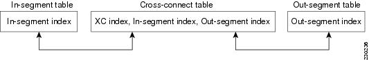
The mplsInSegmentIndex, mplsXCindex, and mplsOutSegmentIndex values are defined as an MplsIndexType, which is a variable-length octet string that can be used to specify an interface index, a physical card or device, or an application ID.
MPLS In-Segment Table Index
The mplsInSegmentIndex is a 4-byte octet string containing the local label.
MPLS Cross-Connect Table Index
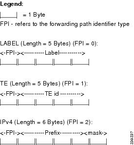
The mplsXCIndex is a variable-length octet string, the size of which depends on the application type that is represented and the amount of information needed to represent the label for that application type. The application type is based on a forwarding path identifier (FPI) type that is supported by the MFI. The Cisco implementation of the MPLS-LSR-STD-MIB for Cisco IOS Release xx.x(x)X supports the following FPI types: LABEL, TE, and IPV4.
Figure 3 shows how the MPLS-LSR-STD-MIB represents the application types for the cross-connect mplsXCIndex object.
Figure 3 MPLS-LSR-STD-MIB Application Type Representation for mplsXCIndex Object
MPLS Out-Segment Table Index
The mplsOutSegmentIndex is a variable-length octet string. The description of this index is identical to that of the mplsXCIndex except the mplsOutSegmentIndex is two bytes longer in length. The last two bytes in the out-segment index contains the MPLS output information (MOI) list index.
Interface Configuration Table and Interface MIB Links
The MPLS interface configuration table lists interfaces that support MPLS technology. An LSR creates an entry dynamically in this table for each MPLS-capable interface. An interface becomes MPLS-capable when MPLS is enabled on that interface. A nonzero index for an entry in this table points to the ifIndex for the corresponding interface entry in the MPLS-layer in the ifTable of the Interfaces Group MIB.
The ifTable contains information on each interface in the network. Its definition of an interface includes any sublayers of the internetwork layer of the interface. MPLS interfaces fit into this definition of an interface. Therefore, each MPLS-enabled interface is represented by an entry in the ifTable.
The interrelation of entries in the ifTable is defined by the interfaces stack group of the Interfaces Group MIB. Figure 4 shows how the stack table might appear for MPLS interfaces. The underlying layer refers to any interface that is defined for MPLS internetworking, for example, ATM, Frame Relay, or Ethernet.
Figure 4 Interface Group MIB Stack Table for MPLS Interfaces
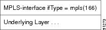
Note ![]() Tunnel interfaces are included in the MPLS list for the current implementation.
Tunnel interfaces are included in the MPLS list for the current implementation.
MPLS-LSR-STD-MIB Structure
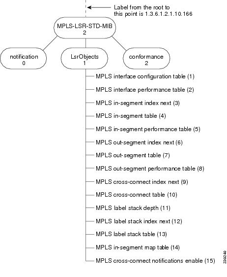
MIB structure is represented by a tree hierarchy. Branches along the tree have short text strings and integers to identify them. Text strings describe object names, and integers allow computer software to encode compact representations of the names.
The MPLS-LSR-STD-MIB falls on the branch of the Internet MIB hierarchy represented by the object identifier 1.3.6.1.2.1.10.166. This branch can also be represented by its object name iso.org.dod.internet.mgmt.mib-2.transmission.mplsStdMIB. The MPLS-LSR-STD-MIB is identified by the object name mplsLsrStdMIB, which is denoted by the number 2. Therefore, objects in the MPLS-LSR-MIB can be identified in either of the following ways:
•![]() The object identifier—1.3.6.1.2.1.10.166.2.[MIB-variable]
The object identifier—1.3.6.1.2.1.10.166.2.[MIB-variable]
•![]() The object name— iso.org.dod.internet.mgmt.mib-2.transmission.mplsStdMIB.mplsLsrStdMIB.[MIB-variable]
The object name— iso.org.dod.internet.mgmt.mib-2.transmission.mplsStdMIB.mplsLsrStdMIB.[MIB-variable]
To display a MIB-variable, you enter an SNMP get command with an object identifier. Object identifiers are defined by the MPLS-LSR-STD-MIB.
Figure 5 shows the position of the MPLS-LSR-STD-MIB in the Internet MIB hierarchy.
Figure 5 MPLS-LSR-STD-MIB in the Internet MIB Hierarchy
CLI Commands and the MPLS-LSR-MIB
The MPLS LFIB is the component of the Cisco MPLS subsystem that contains management information for LSRs. You can access this management information by means of either of the following:
•![]() Using the show mpls forwarding-table CLI command
Using the show mpls forwarding-table CLI command
•![]() Entering SNMP get commands on a network manager
Entering SNMP get commands on a network manager
The following examples show how you can gather LSR management information using both methods.
CLI Command Output
A show mpls forwarding-table CLI command allows you to display label forwarding information for a packet on a specific MPLS LSR:
Router# show mpls forwarding-table
Local Outgoing Prefix Bytes Label Outgoing Next Hop
Label Label or VC or Tunnel Id Switched interface
16 Pop Label IPv4 VRF[V] 1000 aggregate/vpn1
17 Pop Label 10.0.0.3/32 0 PO7/1/0 point2point
18 Pop Label 10.30.1.0/16 0 PO7/1/0 point2point
19 17 10.0.0.1/32 0 PO7/1/0 point2point
20 No Label 10.9.0.0/16[V] 0 GE3/1 10.30.2.2
21 No Label 10.0.0.7/32[V] 128856 GE3/1 10.30.2.2
MPLS-LSR-STD-MIB Output
SNMP commands on MIB objects also allow you to display the label forwarding information for a specific MPLS LSR.
You can do a walk-through of the MIB by running a command such as getmany -v2c public mplsLsrStdMIB on a network manager where getmany does repeated SNMP getnext operations to retrieve the contents of the MPLS-LSR-STD-MIB. Figure 6 shows index information for the mplsXCOperStatus MPLS-LSR-STD-MIB object and how to read the information in the MIB output that follows.
Figure 6 Index Information for the mplsXCOperStatus MPLS-LSR-STD-MIB Object
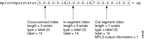
mplsXCOperStatus.5.0.0.0.0.0.4.0.0.0.0.7.0.0.0.0.0.0.1 = up
mplsXCOperStatus.5.0.0.0.0.1.4.0.0.0.1.1.0 = up
mplsXCOperStatus.5.0.0.0.0.2.4.0.0.0.2.7.0.0.0.0.2.0.1 = up
mplsXCOperStatus.5.0.0.0.0.3.4.0.0.0.3.1.0 = up
mplsXCOperStatus.5.0.0.0.0.16.4.0.0.0.16.7.0.0.0.0.16.0.1 = up
mplsXCOperStatus.5.0.0.0.0.17.4.0.0.0.17.7.0.0.0.0.17.0.1 = up
mplsXCOperStatus.5.0.0.0.0.18.4.0.0.0.18.7.0.0.0.0.18.0.1 = up
mplsXCOperStatus.5.0.0.0.0.19.4.0.0.0.19.7.0.0.0.0.19.0.1 = up
mplsXCOperStatus.5.0.0.0.0.20.4.0.0.0.20.1.0 = up
mplsXCOperStatus.5.0.0.0.0.21.4.0.0.0.21.1.0 = up
mplsXCOperStatus.6.2.10.0.0.3.32.1.0.8.2.10.0.0.3.32.0.1 = up
mplsXCOperStatus.6.2.10.30.0.16.1.0.8.2.30.1.0.0.16.0.1 = up
You can continue to scan the output of the getmany command for the following MIB objects from the MPLS out-segment table:
•![]() Out-segment's top label objects (mplsOutSegmentTopLabel)
Out-segment's top label objects (mplsOutSegmentTopLabel)
mplsOutSegmentTopLabel.7.0.0.0.0.0.0.1 = 3
mplsOutSegmentTopLabel.7.0.0.0.0.2.0.1 = 3
mplsOutSegmentTopLabel.7.0.0.0.0.16.0.1 = 3
mplsOutSegmentTopLabel.7.0.0.0.0.17.0.1 = 3
mplsOutSegmentTopLabel.7.0.0.0.0.18.0.1 = 3
mplsOutSegmentTopLabel.7.0.0.0.0.19.0.1 = 17
mplsOutSegmentTopLabel.8.2.10.0.0.1.32.0.1 = 17
mplsOutSegmentTopLabel.8.2.10.0.0.3.32.0.1 = 3
mplsOutSegmentTopLabel.8.2.10.30.0.16.0.1 = 3
•![]() Out-segment's interface (mplsOutSegmentIInterface)
Out-segment's interface (mplsOutSegmentIInterface)
mplsOutSegmentInterface.7.0.0.0.0.0.0.1 = 0
mplsOutSegmentInterface.7.0.0.0.0.2.0.1 = 0
mplsOutSegmentInterface.7.0.0.0.0.16.0.1 = 0
mplsOutSegmentInterface.7.0.0.0.0.17.0.1 = 55
mplsOutSegmentInterface.7.0.0.0.0.18.0.1 = 55
mplsOutSegmentInterface.7.0.0.0.0.19.0.1 = 55
mplsOutSegmentInterface.8.2.10.0.0.1.32.0.1 = 55
mplsOutSegmentInterface.8.2.10.0.0.3.32.0.1 = 55
mplsOutSegmentInterface.8.2.10.30.0.16.0.1 = 55
For more information on how to read the indexing for MPLS-LSR-STD-MIB objects, see Figure 2 and the "MPLS-LSR-STD-MIB Indexing—Linking Table Elements" section.
VPN Aware LSR MIB
Cisco IOS Releases 12.2(33)SRB and 12.2(33)SB include the VPN Aware LSR MIB feature that enables the MPLS-LSR-STD-MIB to get VPN context information. This feature adds support for different contexts for different MPLS VPNs. Users of the MIB can display per-VPN entries in the MPLS-LSR-STD-MIB tables. The VPN Aware LSR MIB feature does not change the syntax of the MPLS-LSR-STD-MIB. It changes the number and types of entries within the tables.
The MPLS-LSR-STD-MIB can show information about only one context at a time. You can specify either a global context or an MPLS VPN context using an SMNP security name. The security name must match the SNMP community name when an SNMP request is performed on a MIB entry.
SNMP Contexts
SNMP contexts provide VPN users with a secure way of accessing MIB data. When a VPN is associated with a context, that VPN's specific MIB data exists in that context. Associating a VPN with a context enables service providers to manage networks with multiple VPNs. Creating and associating a context with a VPN enables a provider to prevent the users of one VPN from accessing information about users of other VPNs on the same networking device.
VPN-aware SNMP requires that SNMP manager and agent entities operating in a VPN environment agree on mapping between the SNMP security name and the VPN name. This mapping is created by you using different contexts for the SNMP data of different VPNs, which is accomplished through the configuration of the SNMP View-based Access Control Model MIB (SNMP-VACM-MIB). The SNMP-VACM-MIB is configured with views so that a user on a VPN with a security name is allowed access to the restricted object space within the context of only that VPN.
SNMP request messages undergo three phases of security and access control before a response message is sent back with the object values within a VPN context:
•![]() The first security phase is authentication of the username. During this phase, the user is authorized for SNMP access.
The first security phase is authentication of the username. During this phase, the user is authorized for SNMP access.
•![]() The second phase is access control. During this phase, the user is authorized for SNMP access to the group objects in the requested SNMP context.
The second phase is access control. During this phase, the user is authorized for SNMP access to the group objects in the requested SNMP context.
•![]() In the third phase, the user can access a particular instance of a table entry. With this third phase, complete retrieval can be based on the SNMP context name.
In the third phase, the user can access a particular instance of a table entry. With this third phase, complete retrieval can be based on the SNMP context name.
IP access lists can be configured and associated with SNMP community strings. This feature enables you to configure an association between VRF instances and SNMP community strings. When a VRF instance is associated with an SNMP community string, SNMP processes requests coming in for a particular community string only if they are received from the configured VRF. If the community string contained in the incoming packet has no VRF associated with it, it is processed only if it came in through a non-VRF interface.
Major Differences Between the MPLS-LSR-STD-MIB and the MPLS-LSR-MIB
The MPLS-LSR-STD-MIB based on RFC 3813 provides the same basic functionality as the MPLS-LSR-MIB based on Version 05 of the IETF MPLS-LSR-MIB. They both provides an interface for managing label switching through the use of SNMP.
After the implementation of the MPLS-LSR-STD-MIB (RFC 3813) in Cisco IOS Releases 12.2(33)SRB and 12.2(33)SRB, the MPLS-LSR-MIB will exist for a period of time before support is completely removed. This gives you the chance to migrate to the MPLS-LSR-STD-MIB. Both MIBs can coexist in the same image because the MPLS-LSR-STD-MIB and the MPLS-LSR-MIB have different root object identifiers (OIDs).
The following sections contain information about the major differences between the MPLS-LSR-STD-MIB and the MPLS-LSR-MIB:
•![]() MPLS-LSR-MIB and the MPLS-LSR-STD-MIB Scalar Object Differences
MPLS-LSR-MIB and the MPLS-LSR-STD-MIB Scalar Object Differences
•![]() MPLS-LSR-MIB and the MPLS-LSR-STD-MIB Table Object Differences
MPLS-LSR-MIB and the MPLS-LSR-STD-MIB Table Object Differences
•![]() MPLS-LSR-MIB and MPLS-LSR-STD-MIB Notification Differences
MPLS-LSR-MIB and MPLS-LSR-STD-MIB Notification Differences
•![]() MPLS-LSR-MIB and MPLS-LSR-STD-MIB Indexing Differences
MPLS-LSR-MIB and MPLS-LSR-STD-MIB Indexing Differences
MPLS-LSR-MIB and the MPLS-LSR-STD-MIB Scalar Object Differences
Table 10 shows the major difference between the MPLS-LSR-MIB objects and the MPLS-LSR-STD-MIB objects for each scalar object.
MPLS-LSR-MIB and the MPLS-LSR-STD-MIB Table Object Differences
The following tables show the major differences between the MPLS-LSR-MIB and the MPLS-LSR-STD-MIB for each table.
MPLS Interface Table (mplsInterfaceTable) Differences
Table 11 shows the difference between MPLS-LSR-MIB and MPLS-LSR-STD-MIB objects for the MPLS interface table (mplsInterfaceTable), formerly called the MPLS interface configuration table (mplsInterfaceConfTable).
MPLS Interface Performance Table (mplsInterfacePerfTable) Differences
Table 12 shows the major difference between MPLS-LSR-MIB and MPLS-LSR-STD-MIB objects for the MPLS interface performance table (mplsInterfacePerfTable).
MPLS In-Segment Table (mplsInSegmentTable) Differences
Table 13 shows the major difference between MPLS-LSR-MIB and MPLS-LSR-STD-MIB objects for the MPLS in-segment table (mplsInSegmentTable).
MPLS In-Segment Performance Table (mplsInSegmentPerfTable) Differences
Table 14 shows the major difference between MPLS-LSR-MIB and MPLS-LSR-STD-MIB objects for the MPLS in-segment performance table (mplsInSegmentPerfTable).
MPLS Out-Segment Table (mplsOutSegmentTable) Differences
Table 15 shows the major difference between MPLS-LSR-MIB and MPLS-LSR-STD-MIB objects for the MPLS out-segment table (mplsOutSegmentTable).
MPLS Out-Segment Performance Table (mplsOutSegmentPerfTable) Differences
Table 16 shows the major difference between MPLS-LSR-MIB and MPLS-LSR-STD-MIB objects for the MPLS out-segment performance table (mplsOutSegmentPerfTable).
MPLS Cross-Connect Table (mplsXCTable) Differences
Table 17 shows the major difference between MPLS-LSR-MIB and MPLS-LSR-STD-MIB objects for the MPLS cross-connect table (mplsXCTable).
MPLS Label Stack Table (mplsLabelStackTable) Differences
Table 18 shows the major difference between MPLS-LSR-MIB and MPLS-LSR-STD-MIB objects for the MPLS label stack table (mplslLabelStackTable).
MPLS In-Segment Map Table (mplsInSegmentMapTable) Differences
Table 19 shows the major difference between MPLS-LSR-MIB and MPLS-LSR-STD-MIB objects for the MPLS in-segment map table (mplsInSegmentMapTable). The MPLS in-segment map table is a new table introduced with the MPLS-LSR-STD-MIB.
MPLS Traffic Parameters Table (mplsTrafficParamTable) Differences
The MPLS traffic parameters table was not supported in Cisco IOS implementation of MPLS-LSR-MIB. It has been removed from the MPLS-LSR-STD-MIB.
MPLS-LSR-MIB and MPLS-LSR-STD-MIB Notification Differences
Table 20 shows the difference between MPLS-LSR-MIB and MPLS-LSR-STD-MIB notifications.
The following notifications were not supported for MPLS-LSR-MIB and are not supported for the MPLS-LSR-STD-MIB in Cisco IOS Releases 12.2(33)SRB and 12.3(33)SB):
•![]() mplsXCUp
mplsXCUp
•![]() mplsXCDown
mplsXCDown
Note ![]() For scalability reasons, none of the notifications were implemented in the Cisco IOS software from the MPLS-LSR-MIB. For the same reason, the notifications from the MPLS-LSR-STD-MIB are not implemented in Cisco IOS Releases 12.2(33)SRB and 12.2(33)SB.
For scalability reasons, none of the notifications were implemented in the Cisco IOS software from the MPLS-LSR-MIB. For the same reason, the notifications from the MPLS-LSR-STD-MIB are not implemented in Cisco IOS Releases 12.2(33)SRB and 12.2(33)SB.
MPLS-LSR-MIB and MPLS-LSR-STD-MIB Indexing Differences
One of the major differences between the MPLS-LSR-MIB and the MPLS-LSR-STD-MIB is the indexing used for the three main tables that manage labels for the MPLS LSR in the MPLS-LSR-MIB and the MPLS-LSR-STD-MIB: the MPLS in-segment table (mplsInSegmentTable), the MPLS cross-connect table (mplsXCTable), and the MPLS out-segment table (mplsOutSegmentTable).
All entries in each table are uniquely identified by one or more indexes. The indexes determine the order in which entries are displayed in a MIB walk.
Table 21 compares indexing characteristics of the draft Version 05 MPLS-LSR-MIB implementation with indexing characteristics of the MPLS-LSR-STD-MIB (RFC 3813) implementation.
For more information about the relationship between the indexes for the MPLS-LSR-STD-MIB implementation, see the "MPLS-LSR-STD-MIB Indexing—Linking Table Elements" section.
How to Configure SNMP for the MPLS EM—MPLS LSR MIB - RFC 3813
This section contains tasks to configure the MPLS EM—MPLS LSR MIB (RFC 3813) feature.
The SNMP agent for the MPLS-LSR-STD-MIB is disabled by default and must be enabled for you to use SNMP to monitor and manage the MPLS LSRs on your network. Perform these task to enable the SNMP Agent and verify that it is enabled:
•![]() Enabling the SNMP Agent (required)
Enabling the SNMP Agent (required)
•![]() Verifying That the SNMP Agent Is Enabled (optional)
Verifying That the SNMP Agent Is Enabled (optional)
Perform the following task to configure a VPN context for the MPLS-LSR-STD-MIB:
•![]() Configuring a VPN-Aware LSR MIB (optional)
Configuring a VPN-Aware LSR MIB (optional)
Prerequisites
The MPLS-LSR-STD-MIB requires the following:
•![]() SNMP installed and enabled on the LSR
SNMP installed and enabled on the LSR
•![]() MPLS enabled on the LSR
MPLS enabled on the LSR
•![]() MFI
MFI
Enabling the SNMP Agent
To enable the SNMP agent, perform the following task.
The SNMP agent for the MPLS-LSR-STD-MIB is disabled by default.
SUMMARY STEPS
1. ![]() enable
enable
2. ![]() show running-config
show running-config
3. ![]() configure terminal
configure terminal
4. ![]() snmp-server community string [view view-name] [ro | rw] [ipv6 nacl] [access-list-number]
snmp-server community string [view view-name] [ro | rw] [ipv6 nacl] [access-list-number]
5. ![]() end
end
6. ![]() save running-config startup-config
save running-config startup-config
DETAILED STEPS
Verifying That the SNMP Agent Is Enabled
To verify that the SNMP agent is enabled, perform the following task.
SUMMARY STEPS
1. ![]() telnet device-ip-address
telnet device-ip-address
2. ![]() enable
enable
3. ![]() show running-config
show running-config
4. ![]() exit
exit
DETAILED STEPS
Step 1 ![]() telnet device-ip-address
telnet device-ip-address
Use this command to access the router through a Telnet session. For example:
Prompt> telnet 10.15.230.20
where 10.15.20.20 represents the IP address of the target device.
Step 2 ![]() enable
enable
Use this command to enable privileged EXEC mode. Enter your password, if prompted. For example:
Router> enable
Router#
Step 3 ![]() show running-config
show running-config
Use this command to display the running configuration. Look for SNMP information. For example:
Router# show running-config
.
.
.
snmp-server community public RO
If you see any "snmp-server" statements, SNMP has been enabled on the router.
Step 4 ![]() exit
exit
Use this command to exit privileged EXEC mode. For example:
Router# exit
Router>
Configuring a VPN-Aware LSR MIB
To configure a VPN-aware LSR MIB, perform the following tasks:
•![]() Configuring SNMP Support for a VPN (required)
Configuring SNMP Support for a VPN (required)
•![]() Configuring an SNMP Context for a VPN (required)
Configuring an SNMP Context for a VPN (required)
•![]() Configuring a VPN-Aware SNMP Context for SNMPv1 or SNMPv2 (required)
Configuring a VPN-Aware SNMP Context for SNMPv1 or SNMPv2 (required)
Configuring SNMP Support for a VPN
To configure SNMP support for a VPN (or a remote VPN), perform the following task. SNMP support for VPNs allows users of the MPLS-LSR-STD-MIB to display per-VPN entries in the MPLS-LSR-STD-MIB tables.
SUMMARY STEPS
1. ![]() enable
enable
2. ![]() configure terminal
configure terminal
3. ![]() snmp-server engineID remote {ipv4-address | ipv6-address} [udp-port udp-port-number]
snmp-server engineID remote {ipv4-address | ipv6-address} [udp-port udp-port-number]
[vrf vrf-name] engineid-string
4. ![]() end
end
DETAILED STEPS
What to Do Next
Proceed to the ""Configuring an SNMP Context for a VPN" section.
Configuring an SNMP Context for a VPN
To configure an SNMP context for a VPN, perform the following task. This sets up a unique SNMP context for a VPN that allows you to access the per-VPN entries in the VRF table.
SNMP Context
SNMP contexts provide VPN users with a secure way of accessing MIB data. When a VPN is associated with a context, that VPN's specific MIB data exists in that context. Associating a VPN with a context enables service providers to manage networks with multiple VPNs. Creating and associating a context with a VPN enables a provider to prevent the users of one VPN from accessing information about users of other VPNs on the same networking device.
VPN Route Distinguishers
A route distinguisher (RD) creates routing and forwarding tables for a VPN. Cisco IOS software adds the RD to the beginning of the customer's IPv4 prefixes to change them into globally unique VPN-IPv4 prefixes.
Either the RD is an autonomous system number (ASN)-relative RD, in which case it is composed of an autonomous system number and an arbitrary number, or it is an IP-address-relative RD, in which case it is composed of an IP address and an arbitrary number. You can enter an RD in either of these formats:
•![]() 16-bit ASN: your 32-bit number, for example, 101:3.
16-bit ASN: your 32-bit number, for example, 101:3.
•![]() 32-bit IP address: your 16-bit number, for example, 192.168.122.15:1.
32-bit IP address: your 16-bit number, for example, 192.168.122.15:1.
SUMMARY STEPS
1. ![]() enable
enable
2. ![]() configure terminal
configure terminal
3. ![]() snmp-server context context-name
snmp-server context context-name
4. ![]() ip vrf vrf-name
ip vrf vrf-name
5. ![]() rd route-distinguisher
rd route-distinguisher
6. ![]() context context-name
context context-name
7. ![]() route-target {import | export | both} route-target-ext-community
route-target {import | export | both}
route-target-ext-community
8. ![]() end
end
DETAILED STEPS
What to Do Next
Proceed to the "Configuring a VPN-Aware SNMP Context for SNMPv1 or SNMPv2" section.
Configuring a VPN-Aware SNMP Context for SNMPv1 or SNMPv2
To configure a VPN-aware SNMP context for SNMPv1 or SNMPv2, perform the following task. This allows you to access per-VPN entries in the MPLS-LSR-STD-MIB tables using SNMPv1 or SNMPv2.
SNMPv1 or SNMPv2 Security
SNMPv1 and SNMPv2 are not as secure as SNMPv3. SNMP Versions 1 and 2 use plain text communities and do not perform the authentication or security checks that SNMP Version 3 performs.
To configure the VPN Aware LSR MIB feature when using SNMP Version 1 or SNMP Version 2, you need to associate a community name with a VPN. This association causes SNMP to process requests coming in for a particular community string only if they come in from the configured VRF. If the community string contained in the incoming packet does not have an associated VRF, the packet is processed only if it came in through a non-VRF interface. This process prevents users outside the VPN from using a clear text community string to query the VPN data. However, this is not as secure as using SNMPv3.
SUMMARY STEPS
1. ![]() enable
enable
2. ![]() configure terminal
configure terminal
3. ![]() snmp-server user username group-name [remote host [udp-port port]] {v1 | v2c | v3 [encrypted]
snmp-server user username group-name [remote host [udp-port port]] {v1 | v2c | v3 [encrypted]
[auth {md5 | sha} auth-password]} [access access-list]
4. ![]() snmp-server group group-name {v1 | v2c | v3 {auth | noauth | priv}} [context context-name]
snmp-server group group-name {v1 | v2c | v3 {auth | noauth | priv}} [context context-name]
[read readview] [write writeview] [notify notifyview] [access access-list]
5. ![]() snmp-server view view-name oid-tree {included | excluded}
snmp-server view view-name oid-tree {included | excluded}
6. ![]() snmp mib community-map community-name [context context-name] [engineid engine-id]
snmp mib community-map community-name [context context-name] [engineid engine-id]
[security-name security-name] target-list vpn-list-name
7. ![]() snmp mib target list vpn-list-name {vrf vrf-name | host ip-address}
snmp mib target list vpn-list-name {vrf vrf-name | host ip-address}
8. ![]() end
end
DETAILED STEPS
Configuration Examples for the MPLS EM—MPLS LSR MIB - RFC 3813
This section contains the following configuration examples for the MPLS EM—MPLS LSR MIB - RFC 3813 feature:
•![]() Enabling the SNMP Agent: Examples
Enabling the SNMP Agent: Examples
•![]() Configuring a VPN-Aware LSR MIB: Example
Configuring a VPN-Aware LSR MIB: Example
Enabling the SNMP Agent: Examples
The following example shows how to enable an SNMP agent.
Router# configure terminal
Router(config)# snmp-server community
In the following example, SNMPv1 and SNMPv2C are enabled. The configuration permits any SNMP manager to access all objects with read-only permissions using the community string public.
Router(config)# snmp-server community public
In the following example, read-only access is allowed for all objects to members of access list 4 that specify the comaccess community string. No other SNMP managers have access to any objects.
Router(config)# snmp-server community comaccess ro 4
Configuring a VPN-Aware LSR MIB: Example
This section contains the following examples for configuring a VPN-aware LSR MIB:
•![]() Configuring SNMP Support for a VPN: Example
Configuring SNMP Support for a VPN: Example
•![]() Configuring an SNMP Context for a VPN: Example
Configuring an SNMP Context for a VPN: Example
•![]() Configuring a VPN-Aware SNMP Context for SNMPv1 or SNMPv2: Example
Configuring a VPN-Aware SNMP Context for SNMPv1 or SNMPv2: Example
Configuring SNMP Support for a VPN: Example
The following example shows how to configure SNMP support for a VPN:
configure terminal
!
snmp-server engineID remote 172.16.20.3 vrf vrf customer1 80000009030000B064EFE100
end
Configuring an SNMP Context for a VPN: Example
The following example shows how to configure an SNMP context for a VPN. In this example, the VPN vrf1 is associated with the SNMP context context1.
configure terminal
!
snmp-server context context-vpn1
ip vrf customer1
rd 100:1
context context-vpn1
route-target export 100:1
end
Configuring a VPN-Aware SNMP Context for SNMPv1 or SNMPv2: Example
The following configuration example shows how to configure a VPN-aware SNMP context for the MPLS LSR MIB with SNMPv1 or SNMPv2:
snmp-server context context-vpn1
ip vrf customer1
rd 100:1
context context-vpn1
route-target export 100:1
route-target import 100:1
!
!
interface Ethernet1/0
ip vrf forwarding customer1
ip address 10.99.99.100 255.0.0.0
mpls label protocol ldp
mpls ip
!
!
interface Serial3/0
ip vrf forwarding customer1
ip address 10.60.1.1 255.0.0.0
mpls label protocol ldp
mpls ip
serial restart-delay 0
!
ip access-list standard context-vpn1
!
snmp-server group group-vpn1 v2c context context-vpn1 read view-vpn1 notify
*tv.00000000.00040000.00000000.0 access context-vpn1
!
snmp-server view view-vpn1 iso included
!
snmp-server community public RW
snmp-server community vrfcomm-vpn1 RW1
!
snmp-server user vrfcomm-vpn1 vrfcomm-vpn1 v1
snmp-server user vrfcomm-vpn1 group-vpn1 v2c
!
snmp mib community-map vrfcomm-vpn1 context context-vpn1 target-list targ-vpn1
!
snmp mib target list targ-vpn1 host 0.0.0.0
snmp mib target list targ-vpn1 vrf customer1
!
Additional References
The following sections provide references related to the MPLS EM—MPLS LSR MIB - RFC 3813 feature.
Related Documents
Standards
|
|
|
|---|---|
No new or modified standards are supported by this feature, and support for existing standards has not been modified by this feature. |
— |
MIBs
|
|
|
|---|---|
• • |
To locate and download MIBs for selected platforms, Cisco IOS releases, and feature sets, use Cisco MIB Locator found at the following URL: |
RFCs
Technical Assistance
Feature Information for MPLS EM—MPLS LSR MIB - RFC 3813
Table 22 lists the release history for this feature.
Not all commands may be available in your Cisco IOS software release. For release information about a specific command, see the command reference documentation.
Use Cisco Feature Navigator to find information about platform support and software image support. Cisco Feature Navigator enables you to determine which Cisco IOS and Catalyst OS software images support a specific software release, feature set, or platform. To access Cisco Feature Navigator, go to http://www.cisco.com/go/cfn. An account on Cisco.com is not required.
Note ![]() Table 22 lists only the Cisco IOS software release that introduced support for a given feature in a given Cisco IOS software release. Unless noted otherwise, subsequent releases of that Cisco IOS software release also support that feature.
Table 22 lists only the Cisco IOS software release that introduced support for a given feature in a given Cisco IOS software release. Unless noted otherwise, subsequent releases of that Cisco IOS software release also support that feature.
|
|
|
|
|---|---|---|
MPLS EM—MPLS LSR MIB - RFC 3813 |
12.2(33)SRB |
The MPLS LSR MIB- RFC 3813 (MPLS-LSR-STD-MIB) allows you to use the Simple Network Management Protocol (SNMP) to remotely monitor a label switch router (LSR) that is using the Multiprotocol Label Switching (MPLS) technology. This document describes the MPLS-LSR-STD-MIB. The document also describes the major differences between the MPLS-LSR-STD-MIB and draft Version 5 of the MPLS-LSR-MIB. The MPLS EM—MPLS LSR MIB - RFC 3813 feature introduces the MPLS-LSR-STD-MIB, which is an upgrade from draft Version 5 of the MPLS-LSR-MIB to an implementation of the Multiprotocol Label Switching (MPLS) Label Switching Router (LSR) Management Information Base (MIB), RFC 3813. This feature also introduces the VPN Aware LSR MIB feature that enables the MPLS-LSR-STD-MIB to get VPN context information. Cisco IOS MPLS Embedded Management (EM) is a set of standards and value-added services that facilitate the deployment, operation, administration, and management of MPLS-based networks in line with the fault, configuration, accounting, performance, and security (FCAPS) model. In 12.2(33)SRB, this feature was introduced. In 12.2(33)SB, this feature was integrated into a Cisco IOS 12.2SB release. |
The following sections provide information about this feature: • • • • • • • • • No commands were introduced or modified for this feature. |
Glossary
cross-connect (XC)—An association of in-segments and incoming MPLS interfaces to out-segments and outgoing MPLS interfaces.
FPI—forwarding path identifier. An identifier required to locate MPLS forwarding information for a FEC. Examples of types of FPIs supported by the MPLS Forwarding Infrastructure (MFI) are IPv4, IPv6, LABEL, SSS, and TE.
IETF—Internet Engineering Task Force. A task force (consisting of more that 80 working groups) that is developing standards for the Internet and the IP suite of protocols.
inSegment—A label on an incoming packet that is used to determine the forwarding of the packet.
label—A short, fixed-length identifier that is used to determine the forwarding of a packet.
label switching—A term used to describe the forwarding of IP (or other network layer) packets using a label swapping algorithm based on network layer routing algorithms. The forwarding of these packets uses the exact match algorithm and rewrites the label.
LDP—Label Distribution Protocol. A standard protocol between MPLS-enabled routers that is used for the negotiation of the labels (addresses) used to forward packets.
LFIB—Label Forwarding Information Base. A data structure and way of managing forwarding in which destinations and incoming labels are associated with outgoing interfaces and labels.
LSP—label switched path. A sequence of hops in which a packet travels from one router to another router by means of label switching mechanisms. A label-switched path can be established dynamically, based on normal routing mechanisms, or through configuration.
LSR—label switching router. A device that forwards MPLS packets based on the value of a fixed-length label encapsulated in each packet.
MFI—MPLS Forwarding Infrastructure. In the Cisco MPLS subsystem, the data structure for storing information about incoming and outgoing labels and associated equivalent packets suitable for labeling.
MIB—Management Information Base. Database of network management information that is used and maintained by a network management protocol such as SNMP. The value of a MIB object can be changed or retrieved by means of SNMP commands, usually through a network management system. MIB objects are organized in a tree structure that includes public (standard) and private (proprietary) branches.
MOI—MPLS output information. The MOI includes the next hop, outgoing interface, and outgoing label.
MPLS—Multiprotocol Label Switching. MPLS is a method for forwarding packets (frames) through a network. It enables routers at the edge of a network to apply labels to packets (frames). ATM switches or existing routers in the network core can switch packets according to the labels with minimal lookup overhead.
MPLS interface—An interface on which MPLS traffic is enabled.
NMS—Network Management Station. A device (usually a workstation) that performs SNMP queries to the SNMP agent of a managed device in order to retrieve or modify information.
notification request—Message sent by an SNMP agent to a network management station, console, or terminal, indicating that a significant event occurred. SNMP notification requests are more reliable than traps, because a notification request from an SNMP agent requires that the SNMP manager acknowledge receipt of the notification request. The manager replies with an SNMP response protocol data unit (PDU). If the manager does not receive a notification message from an SNMP agent, it does not send a response. If the sender (SNMP agent) never receives a response, the notification request can be sent again. Thus, a notification request is more likely than a trap to reach its intended destination.
outSegment—A label on an outgoing packet.
SNMP—Simple Network Management Protocol. Management protocol used almost exclusively in TCP/IP networks. SNMP provides a means for monitoring and controlling network devices, and for managing configurations, statistics collection, performance, and security.
trap—Message sent by an SNMP agent to a network management station, console, or terminal, indicating that a significant event occurred. Traps are less reliable than notification requests, because the receiver does not send an acknowledgment when it receives a trap. The sender cannot determine if the trap was received.
 Feedback