-
- MPLS Traffic Engineering - LSP Attributes
- MPLS Traffic Engineering (TE) - Autotunnel Primary and Backup
- MPLS Traffic Engineering - AutoTunnel Mesh Groups
- MPLS Traffic Engineering - Verbatim Path Support
- MPLS Traffic Engineering - RSVP Hello State Timer
- MPLS Traffic Engineering Forwarding Adjacency
- MPLS Traffic Engineering (TE) - Class-based Tunnel Selection
- MPLS Traffic Engineering - Interarea Tunnels
- MPLS TE - Bundled Interface Support
- MPLS Traffic Engineering�Automatic Bandwidth Adjustment for TE Tunnels
- MPLS Point-to-Multipoint Traffic Engineering
- MPLS Traffic Engineering�Tunnel Source
-
- MPLS Traffic Engineering - Inter-AS TE
- MPLS Traffic Engineering - Shared Risk Link Groups
- MPLS Traffic Engineering (TE) - Autotunnel Primary and Backup
- MPLS Traffic Engineering (TE) - Path Protection
- MPLS Traffic Engineering (TE) - Fast Reroute (FRR) Link and Node Protection
- MPLS TE: Link and Node Protection, with RSVP Hellos Support (with Fast Tunnel Interface Down Detection)
- MPLS Traffic Engineering: BFD-triggered Fast Reroute (FRR)
-
- MPLS MTU Command Changes
- AToM Static Pseudowire Provisioning
- MPLS Pseudowire Status Signaling
- L2VPN Interworking
- L2VPN Pseudowire Redundancy
- L2VPN Pseudowire Switching
- VPLS Autodiscovery: BGP Based
- H-VPLS N-PE Redundancy for QinQ and MPLS Access
- L2VPN Multisegment Pseudowires
- QOS Policy Support on L2VPN ATM PVPs
- L2VPN: Pseudowire Preferential Forwarding
-
- Configuring MPLS Layer 3 VPNs
- MPLS VPN Half-Duplex VRF
- MPLS VPN�Show Running VRF
- MPLS VPN�VRF CLI for IPv4 and IPv6 VPNs
- MPLS VPN--BGP Local Convergence
- MPLS VPN�Route Target Rewrite
- MPLS VPN�Per VRF Label
- MPLS VPN 6VPE per VRF Label
- MPLS Multi-VRF (VRF Lite) Support
- BGP Best External
- BGP PIC Edge for IP and MPLS-VPN
- MPLS VPN - L3VPN over GRE
- Dynamic Layer-3 VPNs with Multipoint GRE Tunnels
- MPLS VPN over mGRE
-
- MPLS LSP Ping/Traceroute for LDP/TE, and LSP Ping for VCCV
- MPLS EM�MPLS LSP Multipath Tree Trace
- Pseudowire Emulation Edge-to-Edge MIBs for Ethernet, Frame Relay, and ATM Services
- MPLS Enhancements to Interfaces MIB
- MPLS Label Distribution Protocol MIB Version 8 Upgrade
- MPLS EM�MPLS LDP MIB - RFC 3815
- MPLS Label Switching Router MIB
- MPLS EM�MPLS LSR MIB - RFC 3813
- MPLS Traffic Engineering MIB
- MPLS Traffic Engineering - Fast Reroute MIB
- MPLS EM - TE MIB RFC 3812
- MPLS VPN�MIB Support
- MPLS EM - MPLS VPN MIB RFC4382 Upgrade
-
- MPLS High Availability: Overview
- MPLS High Availability: Command Changes
- MPLS LDP Graceful Restart
- NSF/SSO - MPLS LDP and LDP Graceful Restart
- NSF/SSO: MPLS VPN
- AToM Graceful Restart
- NSF/SSO�Any Transport over MPLS and AToM Graceful Restart
- NSF/SSO - MPLS TE and RSVP Graceful Restart
- ISSU MPLS Clients
- NSF/SSO/ISSU Support for VPLS
- NSF/SSO and ISSU - MPLS VPN 6VPE and 6PE
Cisco IOS Multiprotocol Label Switching Configuration Guide, Release 12.2SR
Bias-Free Language
The documentation set for this product strives to use bias-free language. For the purposes of this documentation set, bias-free is defined as language that does not imply discrimination based on age, disability, gender, racial identity, ethnic identity, sexual orientation, socioeconomic status, and intersectionality. Exceptions may be present in the documentation due to language that is hardcoded in the user interfaces of the product software, language used based on RFP documentation, or language that is used by a referenced third-party product. Learn more about how Cisco is using Inclusive Language.
- Updated:
- September 6, 2011
Chapter: MPLS VPN - Inter-AS Option AB
- Finding Feature Information
- Contents
- Prerequisites for MPLS VPN—Inter-AS Option AB
- Restrictions for MPLS VPN—Inter-AS Option AB
- Information About MPLS VPN—Inter-AS Option AB
- MPLS VPN—Inter-AS Option AB Introduction
- Benefits of MPLS VPN—Inter-AS Option AB
- Option B Style Peering with Shared Link Forwarding
- MPLS VPN—Inter-AS Option AB Route Distribution and Packet Forwarding in Non-CSC Networks
- MPLS VPN—Inter-AS Option AB Route Distribution and Packet Forwarding for CSC
- MPLS VPN—Inter-AS Option AB+ Shared Link Forwarding in Non-CSC Networks
MPLS VPN—Inter-AS Option AB
The MPLS VPN—Inter-AS Option AB feature combines the best functionality of an Inter-AS Option (10) A and Inter-AS Option (10) B network to allow a Multiprotocol Label Switching (MPLS) Virtual Private Network (VPN) service provider to interconnect different autonomous systems to provide VPN services. These networks are defined in RFC 4364 section 10 "Multi-AS Backbones," subsections a and b, respectively.
When different autonomous systems are interconnected in an MPLS VPN—Inter-AS Option AB configuration, the entire network configuration is scaled and simplified, and maintains IP quality of service (QoS) functions between Autonomous System Boundary Router (ASBR) peers.
In an Inter-AS Option A network, ASBR peers are connected by multiple subinterfaces with at least one interface VPN that spans the two autonomous systems. These ASBRs associate each subinterface with a VPN routing and forwarding (VRF) instance and a Border Gateway Protocol (BGP) session to signal unlabeled IP prefixes. As a result, traffic between the back-to-back VRFs is IP. In this scenario, the VPNs are isolated from each other, and because the traffic is IP, QoS mechanisms that operate on IP traffic can be applied to achieve customer Service Level Agreements (SLAs). The downside of this configuration is that one BGP session is needed for each subinterface (and at least one subinterface for each VPN), which causes scalability concerns as this network grows.
In an Inter-AS Option B network, ASBR peers are connected by one or more subinterfaces that are enabled to receive MPLS traffic. A Multiprotocol Border Gateway Protocol (MP-BGP) session is used to distribute labeled VPN prefixes between the ASBR. As a result, the traffic that flows between them is labeled. The downside of this configuration is that, because the traffic is MPLS, QoS mechanisms that can be applied only to IP traffic cannot be applied and the VRFs cannot be isolated.
Finding Feature Information
Your software release may not support all the features documented in this module. For the latest feature information and caveats, see the release notes for your platform and software release. To find information about the features documented in this module, and to see a list of the releases in which each feature is supported, see the "Feature Information for MPLS VPN—Inter-AS Option AB" section.
Use Cisco Feature Navigator to find information about platform support and Cisco software image support. To access Cisco Feature Navigator, go to http://www.cisco.com/go/cfn. An account on Cisco.com is not required.
Contents
•![]() Prerequisites for MPLS VPN—Inter-AS Option AB
Prerequisites for MPLS VPN—Inter-AS Option AB
•![]() Restrictions for MPLS VPN—Inter-AS Option AB
Restrictions for MPLS VPN—Inter-AS Option AB
•![]() Information About MPLS VPN—Inter-AS Option AB
Information About MPLS VPN—Inter-AS Option AB
•![]() How to Configure Inter-AS Option AB
How to Configure Inter-AS Option AB
•![]() Configuration Examples for MPLS VPN—Inter-AS Option AB
Configuration Examples for MPLS VPN—Inter-AS Option AB
•![]() Feature Information for MPLS VPN—Inter-AS Option AB
Feature Information for MPLS VPN—Inter-AS Option AB
Prerequisites for MPLS VPN—Inter-AS Option AB
Follow the appropriate configuration tasks outlined in the following documents:
•![]() Configuring MPLS Layer 3 VPNs
Configuring MPLS Layer 3 VPNs
•![]() MPLS VPN Inter-AS with ASBRs Exchanging VPN-IPv4 Addresses
MPLS VPN Inter-AS with ASBRs Exchanging VPN-IPv4 Addresses
•![]() MPLS VPN Inter-AS with ASBRs Exchanging IPv4 Routes and MPLS Labels
MPLS VPN Inter-AS with ASBRs Exchanging IPv4 Routes and MPLS Labels
Before configuring the MPLS VPN—Inter-AS Option AB feature, perform these tasks:
•![]() Enable Cisco Express Forwarding, which is required for the MPLS VPN routing and forwarding operation.
Enable Cisco Express Forwarding, which is required for the MPLS VPN routing and forwarding operation.
•![]() Identify the VPNs for the MPLS VPN—Inter-AS Option AB network and configure the VRFs to which these VPNs belong. These VRFs are used for Inter-AS Option AB connections on the ASBR interface.
Identify the VPNs for the MPLS VPN—Inter-AS Option AB network and configure the VRFs to which these VPNs belong. These VRFs are used for Inter-AS Option AB connections on the ASBR interface.
Restrictions for MPLS VPN—Inter-AS Option AB
This feature has these restrictions:
•![]() The In Service Software Upgrade (ISSU) feature can be configured only on the active Route Processor (RP) if the standby RP supports this feature. The ISSU feature can be configured if both the active and standby RP support this feature.
The In Service Software Upgrade (ISSU) feature can be configured only on the active Route Processor (RP) if the standby RP supports this feature. The ISSU feature can be configured if both the active and standby RP support this feature.
•![]() Carrier Supporting Carrier (CSC) MPLS load-balancing on ASBR Option AB VRF interfaces is not supported.
Carrier Supporting Carrier (CSC) MPLS load-balancing on ASBR Option AB VRF interfaces is not supported.
•![]() VPNv6 is not supported.
VPNv6 is not supported.
Information About MPLS VPN—Inter-AS Option AB
•![]() MPLS VPN—Inter-AS Option AB Introduction
MPLS VPN—Inter-AS Option AB Introduction
•![]() Benefits of MPLS VPN—Inter-AS Option AB
Benefits of MPLS VPN—Inter-AS Option AB
•![]() Option B Style Peering with Shared Link Forwarding
Option B Style Peering with Shared Link Forwarding
•![]() MPLS VPN—Inter-AS Option AB Route Distribution and Packet Forwarding in Non-CSC Networks
MPLS VPN—Inter-AS Option AB Route Distribution and Packet Forwarding in Non-CSC Networks
•![]() MPLS VPN—Inter-AS Option AB Route Distribution and Packet Forwarding for CSC
MPLS VPN—Inter-AS Option AB Route Distribution and Packet Forwarding for CSC
•![]() MPLS VPN—Inter-AS Option AB+ Shared Link Forwarding in Non-CSC Networks
MPLS VPN—Inter-AS Option AB+ Shared Link Forwarding in Non-CSC Networks
MPLS VPN—Inter-AS Option AB Introduction
MPLS VPN service providers need to interconnect different autonomous systems to provide service for multiple VPN customers. The MPLS VPN—Inter-AS Option AB feature allows the different autonomous systems to interconnect by using a single MP-BGP session in the global routing table to carry control plane traffic. This MP-BGP session signals VPN prefixes between two ASBRs for each VRF instance. The data plane traffic is on a VRF interface. This traffic can either be IP or MPLS.

Note ![]() Inter-AS connections can be configured between ASBRs that either have or do not have connections between different providers.
Inter-AS connections can be configured between ASBRs that either have or do not have connections between different providers.
Benefits of MPLS VPN—Inter-AS Option AB
The MPLS VPN—Inter-AS Option AB feature provides the following benefits for service providers:
•![]() Network configuration can be simplified because only one BGP session is configured for each VRF on the ASBR.
Network configuration can be simplified because only one BGP session is configured for each VRF on the ASBR.
•![]() One BGP session reduces CPU utilization.
One BGP session reduces CPU utilization.
•![]() Networks can be scaled because a single MP-BGP session, which is enabled globally on the router, reduces the number of sessions required by multiple VPNs, while continuing to keep VPNs isolated and secured from each other.
Networks can be scaled because a single MP-BGP session, which is enabled globally on the router, reduces the number of sessions required by multiple VPNs, while continuing to keep VPNs isolated and secured from each other.
•![]() IP QoS functions between ASBR peers are maintained for customer SLAs.
IP QoS functions between ASBR peers are maintained for customer SLAs.
•![]() Dataplane traffic is isolated on a per-VRF basis for security purposes.
Dataplane traffic is isolated on a per-VRF basis for security purposes.
Option B Style Peering with Shared Link Forwarding
An enhancement to Inter-AS Option AB is the MPLS VPN—Inter-AS Option AB+ feature. This feature addresses the scalability concerns of MPLS VPN—Inter-AS Option A by using a single BGP session in the global routing table to signal VPN prefixes (as described in Inter-AS Option B).
The key difference between Option AB+ and Option B is in the route distribution between ASBRs. In Option AB+, at the ASBR, the route that is imported into the VRF (with the route distinguisher and route targets of the VRF) is distributed to the neighboring ASBR. In Option B, the original pre-import route (with the original RD and RTs) is distributed to the neighboring ASBR and not the imported route.
With Option AB+, the PE and ASBRs deploy MPLS forwarding over a global interface, similar to what is done in Option B, and the signaling is handled by a single MP-eBGP VPNv4 session. The provider edge and ASBRs thus use regular Option B style peering between them. They receive MPLS-VPN traffic over the shared link and forward the traffic as per an IP lookup in the VRF routing table. However, the traffic is MPLS encapsulated, like it is in Option B.
MPLS VPN—Inter-AS Option AB Route Distribution and Packet Forwarding in Non-CSC Networks
The following sections describe MPLS VPN—Inter-AS Option AB operation:
Note ![]() All imported routes are accomplished by configuring the appropriate route targets (RTs).
All imported routes are accomplished by configuring the appropriate route targets (RTs).
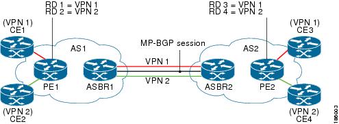
The following attributes describe the topology of the sample MPLS VPN—Inter-AS Option AB network shown in Figure 1:
•![]() Customer edge 1 (CE1) and CE3 belong to VPN 1.
Customer edge 1 (CE1) and CE3 belong to VPN 1.
•![]() CE2 and CE 4 belong to VPN 2.
CE2 and CE 4 belong to VPN 2.
•![]() Provider edge 1 (PE1) uses route distinguisher 1 (RD 1) for VPN 1 (VRF 1) and RD 2 for VPN 2 (VRF 2).
Provider edge 1 (PE1) uses route distinguisher 1 (RD 1) for VPN 1 (VRF 1) and RD 2 for VPN 2 (VRF 2).
•![]() PE2 uses RD 3 for VPN 1 (VRF 1) and RD 4 for VPN 2 (VRF 2).
PE2 uses RD 3 for VPN 1 (VRF 1) and RD 4 for VPN 2 (VRF 2).
•![]() ASBR1 has VRF 1 provisioned with RD 5 and VRF 2 provisioned with RD 6.
ASBR1 has VRF 1 provisioned with RD 5 and VRF 2 provisioned with RD 6.
•![]() ASBR2 has VRF 1 provisioned with RD 7 and VRF 2 provisioned and RD 8.
ASBR2 has VRF 1 provisioned with RD 7 and VRF 2 provisioned and RD 8.
•![]() ASBR1 and ASBR2 have three links between them:
ASBR1 and ASBR2 have three links between them:
–![]() VRF 1
VRF 1
–![]() VRF 2
VRF 2
–![]() MP-BGP session
MP-BGP session
Note ![]() The VRFs configured on the ASBRs are called Option AB VRFs. The eBGP peers on the ASBRs are called Option AB Peers.
The VRFs configured on the ASBRs are called Option AB VRFs. The eBGP peers on the ASBRs are called Option AB Peers.
Figure 1 MPLS VPN Inter-AS Option AB Topology
Route Distribution for VPN 1
A route distinguisher (RD) is an identifier attached to a route that identifies which VPN belongs to each route. Each routing instance must have a unique RD autonomous system associated with it. The RD is used to place a boundary around a VPN so that the same IP address prefixes can be used in different VPNs without having these IP address prefixes overlap.
Note ![]() An RD statement is required if the instance type is a VRF.
An RD statement is required if the instance type is a VRF.
The following process describes the route distribution process for VPN 1 in Figure 1. Prefix "N" is used in this process to indicate the IP address of a VPN.
1. ![]() CE1 advertises the prefix N to PE1.
CE1 advertises the prefix N to PE1.
2. ![]() PE1 advertises a VPN prefix RD 1:N to ASBR1 through MP internal BGP (iBGP).
PE1 advertises a VPN prefix RD 1:N to ASBR1 through MP internal BGP (iBGP).
3. ![]() ASBR1 imports the prefix into VPN 1 and creates a prefix RD 5:N.
ASBR1 imports the prefix into VPN 1 and creates a prefix RD 5:N.
4. ![]() ASBR1 advertises the imported prefix RD 5:N to ASBR2. ASBR1 sets itself as the next hop for prefix RD 5:N and allocates a local label that is signaled with this prefix.
ASBR1 advertises the imported prefix RD 5:N to ASBR2. ASBR1 sets itself as the next hop for prefix RD 5:N and allocates a local label that is signaled with this prefix.
5. ![]() ASBR1 advertises the route with the export RT configured on the VRF rather than the originally received RTs. By default, ASBR1 does not advertise the source prefix RD 1:N to ASBR2. This advertisement is suppressed because the prefix is being imported into an Option AB VRF.
ASBR1 advertises the route with the export RT configured on the VRF rather than the originally received RTs. By default, ASBR1 does not advertise the source prefix RD 1:N to ASBR2. This advertisement is suppressed because the prefix is being imported into an Option AB VRF.
Note ![]() In an Option 10B connection, the source prefix can be advertised to another ASBR on which ASBR1 has an Option 10B connection. An ASBR with an Option 10B connection maintains all VPNv4 routes in its BGP table.
In an Option 10B connection, the source prefix can be advertised to another ASBR on which ASBR1 has an Option 10B connection. An ASBR with an Option 10B connection maintains all VPNv4 routes in its BGP table.
6. ![]() ASBR2 receives the prefix RD 5:N and imports it into VPN 1 as RD 7:N.
ASBR2 receives the prefix RD 5:N and imports it into VPN 1 as RD 7:N.
7. ![]() ASBR2 advertises the route with the export RT configured on the VRF rather than the originally received RTs.
ASBR2 advertises the route with the export RT configured on the VRF rather than the originally received RTs.
8. ![]() While importing the prefix, ASBR2 sets the next hop of RD 7:N to the ASBR1 interface IP address in VRF 1. The next hop table ID is also set to VRF 1. When installing the MPLS forwarding entry for RD 7:N, by default ASBR2 does not install the outgoing label in the forwarding process. This enables the traffic between the ASBRs to be IP.
While importing the prefix, ASBR2 sets the next hop of RD 7:N to the ASBR1 interface IP address in VRF 1. The next hop table ID is also set to VRF 1. When installing the MPLS forwarding entry for RD 7:N, by default ASBR2 does not install the outgoing label in the forwarding process. This enables the traffic between the ASBRs to be IP.
9. ![]() ASBR2 advertises the imported prefix RD 7:N to PE2. It sets itself as the next hop for this prefix and also allocates a local label that is signaled with the prefix. By default, ASBR2 does not advertise the source prefix RD 5:N to PE2. This advertisement is suppressed because the prefix is being imported into an Option AB VRF.
ASBR2 advertises the imported prefix RD 7:N to PE2. It sets itself as the next hop for this prefix and also allocates a local label that is signaled with the prefix. By default, ASBR2 does not advertise the source prefix RD 5:N to PE2. This advertisement is suppressed because the prefix is being imported into an Option AB VRF.
10. ![]() PE2 imports the RD 7:N into VRF 1 as RD 3:N.
PE2 imports the RD 7:N into VRF 1 as RD 3:N.
Packet Forwarding for VPN 1
The following packet forwarding process works the same as it does in an Option A scenario. The ASBR acts like the PE by terminating the VPN and then forwards its traffic as standard IP packets with no VPN label to the next PE, which in turn repeats the VPN process. Each PE router, therefore, treats the adjacent PE router as a CE router, and the standard Layer 3 MPLS VPN mechanisms are used for route redistribution with each autonomous system; that is, the PEs use external BGP (eBGP) to distribute unlabeled IPv4 addresses to each other.
Note ![]() Prefix "N" is used in this process to indicate the IP address of a VPN.
Prefix "N" is used in this process to indicate the IP address of a VPN.
1. ![]() CE3 sends a packet destined for N to PE2.
CE3 sends a packet destined for N to PE2.
2. ![]() PE2 encapsulates the packet with the VPN label allocated by ASBR2 and the Interior Gateway Protocol (IGP) label needed to tunnel the packet to ASBR2.
PE2 encapsulates the packet with the VPN label allocated by ASBR2 and the Interior Gateway Protocol (IGP) label needed to tunnel the packet to ASBR2.
3. ![]() The packet arrives on ASBR2 with the VPN label. ASBR2 removes the VPN label and sends the packet as IP to ASBR1 on the VRF 1 interface.
The packet arrives on ASBR2 with the VPN label. ASBR2 removes the VPN label and sends the packet as IP to ASBR1 on the VRF 1 interface.
4. ![]() The IP packet arrives at ASBR1 on the VRF 1 interface. ASBR1 then encapsulates the packet with the VPN label allocated by PE1 and the IGP label needed to tunnel the packet to PE1.
The IP packet arrives at ASBR1 on the VRF 1 interface. ASBR1 then encapsulates the packet with the VPN label allocated by PE1 and the IGP label needed to tunnel the packet to PE1.
5. ![]() The packet arrives on PE1 with the VPN label. PE1 disposes the VPN label and forwards the IP packet to CE1.
The packet arrives on PE1 with the VPN label. PE1 disposes the VPN label and forwards the IP packet to CE1.
Route Distribution for VPN 2
The following information describes the route distribution process for VPN 2 in Figure 1:
1. ![]() CE2 advertises prefix N to PE1, where N is the VPN IP address.
CE2 advertises prefix N to PE1, where N is the VPN IP address.
2. ![]() PE1 advertises a VPN prefix RD 2:N to ASBR1 through MP-iBGP.
PE1 advertises a VPN prefix RD 2:N to ASBR1 through MP-iBGP.
3. ![]() ASBR1 imports the prefix into VPN 2 and creates a prefix RD 6:N.
ASBR1 imports the prefix into VPN 2 and creates a prefix RD 6:N.
4. ![]() ASBR1 advertises the imported prefix RD 6:N to ASBR2. It sets itself as the next hop for this prefix and also allocates a local label that is signaled with the prefix. By default, ASBR1 does not advertise the source prefix RD 2:N to ASBR2. This advertisement is suppressed as the prefix is being imported into an Option AB VRF.
ASBR1 advertises the imported prefix RD 6:N to ASBR2. It sets itself as the next hop for this prefix and also allocates a local label that is signaled with the prefix. By default, ASBR1 does not advertise the source prefix RD 2:N to ASBR2. This advertisement is suppressed as the prefix is being imported into an Option AB VRF.
Note ![]() In the case of an Option 10B connection, the source prefix can be advertised to another ASBR on which ASBR1 has an Option 10B connection. An ASBR with an Option 10B connection maintains all VPNv4 routes in its BGP table.
In the case of an Option 10B connection, the source prefix can be advertised to another ASBR on which ASBR1 has an Option 10B connection. An ASBR with an Option 10B connection maintains all VPNv4 routes in its BGP table.
5. ![]() ASBR2 receives the prefix RD 6:N and imports it into VPN 2 as RD 8:N.
ASBR2 receives the prefix RD 6:N and imports it into VPN 2 as RD 8:N.
6. ![]() While importing the prefix, ASBR2 sets the next hop of RD 8:N to ASBR1s interface address in VRF 2. The next hop table ID is also set to that of VRF 2. While installing the MPLS forwarding entry for RD 8:N, by default ASBR2 does not install the outgoing label in the forwarding process. This enables traffic between the ASBRs to be IP.
While importing the prefix, ASBR2 sets the next hop of RD 8:N to ASBR1s interface address in VRF 2. The next hop table ID is also set to that of VRF 2. While installing the MPLS forwarding entry for RD 8:N, by default ASBR2 does not install the outgoing label in the forwarding process. This enables traffic between the ASBRs to be IP.
7. ![]() ASBR2 advertises the imported prefix RD 8:N to PE2. It sets itself as the next hop for this prefix and also allocates a local label that is signaled with the prefix. By default, ASBR2 does not advertise the source prefix RD 6:N to PE2. This advertisement is suppressed because the prefix is being imported into an Option AB VRF.
ASBR2 advertises the imported prefix RD 8:N to PE2. It sets itself as the next hop for this prefix and also allocates a local label that is signaled with the prefix. By default, ASBR2 does not advertise the source prefix RD 6:N to PE2. This advertisement is suppressed because the prefix is being imported into an Option AB VRF.
8. ![]() PE2 imports the RD 8:N into VRF 2 as RD 4:N.
PE2 imports the RD 8:N into VRF 2 as RD 4:N.
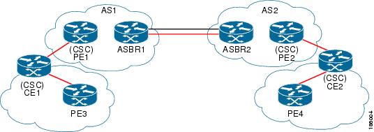
MPLS VPN—Inter-AS Option AB Route Distribution and Packet Forwarding for CSC
The following sections describe MPLS VPN—Inter-AS Option AB operation for a CSC scenario for VPN 1. These sections are similar to those found in "MPLS VPN—Inter-AS Option AB Route Distribution and Packet Forwarding in Non-CSC Networks" section for VPN 1, except for the method in which MPLS labels are handled between the two ASBRs.
Note ![]() VPN 2 is not shown or discussed in this section.
VPN 2 is not shown or discussed in this section.
Figure 2 shows how VPN 1 provides VPN service to a small customer carrier that in turn provides a VPN service to its customer. This configuration implies that VPN 1 is used to provide a label switched path (LSP) between the PE (PE 3 and PE 4) loopback interfaces of the small customer carrier.
Figure 2 MPLS VPN Inter-AS Option AB CSC Topology
Note ![]() The RD, RT, VRF, and Link provisioning in this section is the same as in the "MPLS VPN—Inter-AS Option AB Route Distribution and Packet Forwarding in Non-CSC Networks" section example for VPN 1.
The RD, RT, VRF, and Link provisioning in this section is the same as in the "MPLS VPN—Inter-AS Option AB Route Distribution and Packet Forwarding in Non-CSC Networks" section example for VPN 1.
Route Distribution for VPN 1
The following information describe the route distribution process for VPN 1 in Figure 1. Prefix "N" is used in these steps to indicate the IP address of a VPN.
1. ![]() CE1 advertises PE 3 loopback N to PE1.
CE1 advertises PE 3 loopback N to PE1.
2. ![]() PE1 advertises a VPN prefix RD 1:N to ASBR1 through MP-iBGP.
PE1 advertises a VPN prefix RD 1:N to ASBR1 through MP-iBGP.
3. ![]() ASBR1 imports the prefix into VPN 1 and creates a prefix RD 5:N.
ASBR1 imports the prefix into VPN 1 and creates a prefix RD 5:N.
4. ![]() ASBR1 advertises the imported prefix RD 5:N to ASBR2. It sets itself as the next hop for this prefix and also allocates a local label that is signaled with the prefix.
ASBR1 advertises the imported prefix RD 5:N to ASBR2. It sets itself as the next hop for this prefix and also allocates a local label that is signaled with the prefix.
5. ![]() ASBR1 advertises the route with the export RT configured on the VRF rather than the originally received RTs. By default, ASBR1 does not advertise the source prefix RD 1:N to ASBR2. This advertisement is suppressed as the prefix is being imported into an Option AB VRF.
ASBR1 advertises the route with the export RT configured on the VRF rather than the originally received RTs. By default, ASBR1 does not advertise the source prefix RD 1:N to ASBR2. This advertisement is suppressed as the prefix is being imported into an Option AB VRF.
Note ![]() In an Option 10B connection, the source prefix can be advertised to another ASBR on which ASBR1 has an Option 10B connection. An ASBR with an Option 10B connection maintains all VPNv4 routes in its BGP table.
In an Option 10B connection, the source prefix can be advertised to another ASBR on which ASBR1 has an Option 10B connection. An ASBR with an Option 10B connection maintains all VPNv4 routes in its BGP table.
6. ![]() ASBR2 receives the prefix RD 5:N and imports it into VPN 1 as RD 7:N.
ASBR2 receives the prefix RD 5:N and imports it into VPN 1 as RD 7:N.
7. ![]() ASBR2 advertises the route with the export RT configured on the VRF rather than the originally received RTs.
ASBR2 advertises the route with the export RT configured on the VRF rather than the originally received RTs.
8. ![]() While importing the prefix, ASBR2 sets the next hop of RD 7:N to the ASBR1 interface address in VRF 1. The next hop table ID is also set to that of VRF 1.
While importing the prefix, ASBR2 sets the next hop of RD 7:N to the ASBR1 interface address in VRF 1. The next hop table ID is also set to that of VRF 1.
Note ![]() In a CSC scenario, an outgoing MPLS label can be installed in forwarding by making a configuration change. See the "How to Configure Inter-AS Option AB" section.
In a CSC scenario, an outgoing MPLS label can be installed in forwarding by making a configuration change. See the "How to Configure Inter-AS Option AB" section.
9. ![]() While installing the MPLS forwarding entry for RD 7:N, ASBR2 installs the outgoing label during the forwarding process, which enables the traffic between the ASBRs to be MPLS traffic.
While installing the MPLS forwarding entry for RD 7:N, ASBR2 installs the outgoing label during the forwarding process, which enables the traffic between the ASBRs to be MPLS traffic.
10. ![]() ASBR2 advertises the imported prefix RD 7:N to PE2. It sets itself as the next hop for this prefix and also allocates a local label that is signaled with the prefix. By default, ASBR2 does not advertise the source prefix RD 5:N to PE2. This advertisement is suppressed as the prefix is being imported into an Option AB VRF.
ASBR2 advertises the imported prefix RD 7:N to PE2. It sets itself as the next hop for this prefix and also allocates a local label that is signaled with the prefix. By default, ASBR2 does not advertise the source prefix RD 5:N to PE2. This advertisement is suppressed as the prefix is being imported into an Option AB VRF.
11. ![]() PE2 imports the RD 7:N into VRF 1 as RD 3:N.
PE2 imports the RD 7:N into VRF 1 as RD 3:N.
Packet Forwarding for VPN 1
The packet forwarding process shown below works the same as it does in an Option A scenario. See the "MPLS VPN—Inter-AS Option AB Route Distribution and Packet Forwarding in Non-CSC Networks" section for more information about Option A.
1. ![]() PE 4 sends an MPLS packet destined for N to CE2.
PE 4 sends an MPLS packet destined for N to CE2.
2. ![]() CE2 swaps the MPLS label and sends a packet destined for N to PE2.
CE2 swaps the MPLS label and sends a packet destined for N to PE2.
3. ![]() PE2 encapsulates the packet with the VPN label allocated by ASBR2 and the IGP label needed to tunnel the packet to ASBR2.
PE2 encapsulates the packet with the VPN label allocated by ASBR2 and the IGP label needed to tunnel the packet to ASBR2.
4. ![]() The packet arrives on ASBR2 with the VPN label. ASBR2 swaps the received VPN label with the outgoing label received from ASBR1 and sends the MPLS packet on to the VRF 1 interface.
The packet arrives on ASBR2 with the VPN label. ASBR2 swaps the received VPN label with the outgoing label received from ASBR1 and sends the MPLS packet on to the VRF 1 interface.
5. ![]() The MPLS packet arrives at ASBR1 on the VRF 1 interface. ASBR1 then swaps the received MPLS label with a label stack consisting of the VPN label allocated by PE1 and the IGP label needed to tunnel the packet to PE1.
The MPLS packet arrives at ASBR1 on the VRF 1 interface. ASBR1 then swaps the received MPLS label with a label stack consisting of the VPN label allocated by PE1 and the IGP label needed to tunnel the packet to PE1.
6. ![]() The packet arrives on PE1 with the VPN label. PE1 disposes the VPN label and forwards the MPLS packet to CE1. CE1 in turn swaps the label and forwards the labeled packet to PE 3.
The packet arrives on PE1 with the VPN label. PE1 disposes the VPN label and forwards the MPLS packet to CE1. CE1 in turn swaps the label and forwards the labeled packet to PE 3.
MPLS VPN—Inter-AS Option AB+ Shared Link Forwarding in Non-CSC Networks
The following sections describe MPLS VPN—Inter-AS Option AB+ shared link forwarding in a non-CSC network:
Note ![]() All imported routes are accomplished by configuring the appropriate route targets (RTs).
All imported routes are accomplished by configuring the appropriate route targets (RTs).
The following attributes describe the sample network topology shown in Figure 1:
•![]() Customer edge 1 (CE1) and CE3 belong to VPN 1.
Customer edge 1 (CE1) and CE3 belong to VPN 1.
•![]() CE2 and CE 4 belong to VPN 2.
CE2 and CE 4 belong to VPN 2.
•![]() Provider edge 1 (PE1) uses route distinguisher 1 (RD 1) for VPN 1 (VRF 1) and RD 2 for VPN 2 (VRF 2).
Provider edge 1 (PE1) uses route distinguisher 1 (RD 1) for VPN 1 (VRF 1) and RD 2 for VPN 2 (VRF 2).
•![]() PE2 uses RD 3 for VPN 1 (VRF 1) and RD 4 for VPN 2 (VRF 2).
PE2 uses RD 3 for VPN 1 (VRF 1) and RD 4 for VPN 2 (VRF 2).
•![]() ASBR1 has VRF 1 provisioned with RD 5 and VRF 2 provisioned with RD 6.
ASBR1 has VRF 1 provisioned with RD 5 and VRF 2 provisioned with RD 6.
•![]() ASBR2 has VRF 1 provisioned with RD 7 and VRF 2 provisioned and RD 8.
ASBR2 has VRF 1 provisioned with RD 7 and VRF 2 provisioned and RD 8.
•![]() ASBR1 and ASBR2 have three links between them:
ASBR1 and ASBR2 have three links between them:
–![]() VRF 1
VRF 1
–![]() VRF 2
VRF 2
–![]() MP-BGP session
MP-BGP session
Note ![]() The VRFs configured on the ASBRs are called Option AB+ VRFs. The eBGP peers on the ASBRs are called Option AB+ Peers.
The VRFs configured on the ASBRs are called Option AB+ VRFs. The eBGP peers on the ASBRs are called Option AB+ Peers.
Route Distribution for VPN 1
The following process describes the route distribution process for VPN 1 in Figure 1. Prefix "N" is used in this process to indicate the IP address of a VPN.
1. ![]() CE1 advertises the prefix N to PE1.
CE1 advertises the prefix N to PE1.
2. ![]() PE1 advertises a VPN prefix RD 1:N to ASBR1 through MP internal BGP (iBGP).
PE1 advertises a VPN prefix RD 1:N to ASBR1 through MP internal BGP (iBGP).
3. ![]() ASBR1 imports the prefix into VPN 1 and creates a prefix RD 5:N.
ASBR1 imports the prefix into VPN 1 and creates a prefix RD 5:N.
4. ![]() ASBR1 advertises the imported prefix RD 5:N to ASBR2. ASBR1 sets itself as the next hop for prefix RD 5:N and allocates a local label that is signaled with this prefix.
ASBR1 advertises the imported prefix RD 5:N to ASBR2. ASBR1 sets itself as the next hop for prefix RD 5:N and allocates a local label that is signaled with this prefix.
5. ![]() By default, ASBR1 does not advertise the source prefix RD 1:N to ASBR2. This advertisement is suppressed because the prefix is being imported into an Option AB+ VRF.
By default, ASBR1 does not advertise the source prefix RD 1:N to ASBR2. This advertisement is suppressed because the prefix is being imported into an Option AB+ VRF.
Note ![]() In an Option 10B connection, the source prefix can be advertised to another ASBR on which ASBR1 has an Option 10B connection. An ASBR with an Option 10B connection maintains all VPNv4 routes in its BGP table.
In an Option 10B connection, the source prefix can be advertised to another ASBR on which ASBR1 has an Option 10B connection. An ASBR with an Option 10B connection maintains all VPNv4 routes in its BGP table.
6. ![]() ASBR2 receives the prefix RD 5:N and imports it into VPN 1 as RD 7:N.
ASBR2 receives the prefix RD 5:N and imports it into VPN 1 as RD 7:N.
7. ![]() While importing the prefix, ASBR2 retains the next hop of RD7:N as received in the BGP update from ASBR2. This is the address of ASBR1 shared interface address in the global table. The next hop tableid is also left unchanged and corresponds to that of the global table.
While importing the prefix, ASBR2 retains the next hop of RD7:N as received in the BGP update from ASBR2. This is the address of ASBR1 shared interface address in the global table. The next hop tableid is also left unchanged and corresponds to that of the global table.
8. ![]() When installing the MPLS forwarding entry for RD 7:N, ASBR2 installs the outgoing label in the forwarding process. This enables the traffic between the ASBRs to be IP.
When installing the MPLS forwarding entry for RD 7:N, ASBR2 installs the outgoing label in the forwarding process. This enables the traffic between the ASBRs to be IP.
9. ![]() ASBR2 advertises the imported prefix RD 7:N to PE2. It sets itself as the next hop for this prefix and also allocates a local label that is signaled with the prefix.
ASBR2 advertises the imported prefix RD 7:N to PE2. It sets itself as the next hop for this prefix and also allocates a local label that is signaled with the prefix.
10. ![]() By default, ASBR2 does not advertise the source prefix RD 5:N to PE2. This advertisement is suppressed because the prefix is being imported into an Option AB+ VRF.
By default, ASBR2 does not advertise the source prefix RD 5:N to PE2. This advertisement is suppressed because the prefix is being imported into an Option AB+ VRF.
11. ![]() PE2 imports the RD 7:N into VRF 1 as RD 3:N.
PE2 imports the RD 7:N into VRF 1 as RD 3:N.
Packet Forwarding for VPN 1
The following packet forwarding process works the same as it does in an Option B scenario.
1. ![]() CE3 sends a packet destined for N to PE2.
CE3 sends a packet destined for N to PE2.
2. ![]() PE2 encapsulates the packet with the VPN label allocated by ASBR2 and the IGP label needed to tunnel the packet to ASBR2.
PE2 encapsulates the packet with the VPN label allocated by ASBR2 and the IGP label needed to tunnel the packet to ASBR2.
3. ![]() The packet arrives on ASBR2 with the VPN label. ASBR2 swaps the received VPN label with the outgoing label received from ASBR1 and sends the MPLS packet on the global shared link interface.
The packet arrives on ASBR2 with the VPN label. ASBR2 swaps the received VPN label with the outgoing label received from ASBR1 and sends the MPLS packet on the global shared link interface.
4. ![]() The MPLS packet arrives at ASBR1 on the global shared link interface. ASBR1 then swaps the received MPLS label with a label stack consisting of the VPN label allocated by PE1 and the IGP label needed to tunnel the packet to PE1.
The MPLS packet arrives at ASBR1 on the global shared link interface. ASBR1 then swaps the received MPLS label with a label stack consisting of the VPN label allocated by PE1 and the IGP label needed to tunnel the packet to PE1.
5. ![]() The packet arrives on PE1 with the VPN label. PE1 removes the VPN label and forwards the IP packet to CE1.
The packet arrives on PE1 with the VPN label. PE1 removes the VPN label and forwards the IP packet to CE1.
How to Configure Inter-AS Option AB
The following sections describe how to configure the Inter-AS Option AB feature on an ASBR for either an MPLS VPN or an MPLS VPN that supports CSC:
•![]() Configuring an Inter-AS Option AB Connection (required)
Configuring an Inter-AS Option AB Connection (required)
•![]() Changing an Inter-AS Option A Deployment to an Option AB Deployment (optional)
Changing an Inter-AS Option A Deployment to an Option AB Deployment (optional)
Configuring an Inter-AS Option AB Connection
The following sections are required and describe how to configure an Inter-AS Option AB connection on an ASBR.
If Inter-AS Option AB is already deployed in your network and you want to do Option B style peering for some prefixes (that is, implement Inter-AS Option AB+), configure the inter-as-hybrid global command as described in the "Configuring the Routing Policy for VPNs that Need Inter-AS Connections" section.
•![]() Configuring the VRFs on the ASBR Interface for Each VPN Customer
Configuring the VRFs on the ASBR Interface for Each VPN Customer
•![]() Configuring the MP-BGP Session Between ASBR Peers
Configuring the MP-BGP Session Between ASBR Peers
•![]() Configuring the Routing Policy for VPNs that Need Inter-AS Connections
Configuring the Routing Policy for VPNs that Need Inter-AS Connections
Note ![]() See the Configuring MPLS Layer 3 VPNs feature module for more information on configuring PE and CE routers in an MPLS VPN.
See the Configuring MPLS Layer 3 VPNs feature module for more information on configuring PE and CE routers in an MPLS VPN.
Configuring the VRFs on the ASBR Interface for Each VPN Customer
Use the following steps to configure the VRFs on the ASBR interface for each VPN customer so that these VPNs have connectivity over the MPLS VPN—Inter-AS Option AB network.
Note ![]() The mpls bgp forwarding command is used only on the ASBR interface for VRFs that support CSC.
The mpls bgp forwarding command is used only on the ASBR interface for VRFs that support CSC.
Use all of the steps in the following procedure to configure additional VRFs that need to be configured on the ASBR interface and the VRFs that need to be configured on the peer ASBR interface.
SUMMARY STEPS
1. ![]() enable
enable
2. ![]() configure terminal
configure terminal
3. ![]() interface type number
interface type number
4. ![]() ip vrf forwarding vrf-name
ip vrf forwarding vrf-name
5. ![]() mpls bgp forwarding
mpls bgp forwarding
6. ![]() end
end
DETAILED STEPS
Configuring the MP-BGP Session Between ASBR Peers
BGP propagates reachability information for VPN-IPv4 prefixes among PE routers by means of the BGP multiprotocol extensions (see RFC 2283, Multiprotocol Extensions for BGP-4), which define support for address families other than IPv4. Using the extensions ensures that the routes for a given VPN are learned only by other members of that VPN, enabling members of the VPN to communicate with each other.
Follow the steps in this section to configure the MP-BGP session on the ASBR.
Use all of the steps in the following procedure to configure the MP BGP session on the peer ASBR.
SUMMARY STEPS
1. ![]() enable
enable
2. ![]() configure terminal
configure terminal
3. ![]() router bgp as-number
router bgp as-number
4. ![]() neighbor {ip-address | peer-group-name} remote-as as-number
neighbor {ip-address | peer-group-name} remote-as as-number
5. ![]() address-family vpnv4 [unicast]
address-family vpnv4 [unicast]
6. ![]() neighbor {ip-address | peer-group-name} activate
neighbor {ip-address | peer-group-name} activate
7. ![]() neighbor {ip-address | peer-group-name} inter-as-hybrid
neighbor {ip-address | peer-group-name} inter-as-hybrid
8. ![]() exit-address-family
exit-address-family
9. ![]() end
end
DETAILED STEPS
Configuring the Routing Policy for VPNs that Need Inter-AS Connections
Use the steps in this section to configure VRFs for the VPNs that need Inter-AS connections between ASBR peers, by configuring the appropriate routing policy and Option AB configuration.
Use the steps in the following procedure to configure additional VPNs that need Inter-AS Option AB connectivity on this ASBR and the peer ASBR.
SUMMARY STEPS
1. ![]() enable
enable
2. ![]() configure terminal
configure terminal
3. ![]() vrf definition vrf-name
vrf definition vrf-name
4. ![]() rd route-distinguisher
rd route-distinguisher
5. ![]() address-family ipv4
address-family ipv4
6. ![]() route-target {import | export | both} route-target-ext-community
route-target {import | export | both}
route-target-ext-community
7. ![]() For Inter-AS Option AB+, go to Step 10+; otherwise, go to Step 8.
For Inter-AS Option AB+, go to Step 10+; otherwise, go to Step 8.
8. ![]() inter-as-hybrid [csc]
inter-as-hybrid [csc]
9. ![]() inter-as-hybrid [csc] [next-hop ip-address]
inter-as-hybrid [csc] [next-hop ip-address]
10. ![]() inter-as-hybrid [next-hop ip-address] global
inter-as-hybrid [next-hop ip-address] global
11. ![]() end
end
DETAILED STEPS
Changing an Inter-AS Option A Deployment to an Option AB Deployment
In an Option A deployment, the VRF instances are back-to-back between the ASBR routers and there is direct connectivity between PE routers of different autonomous systems. The PE routers are attached by multiple physical or logical interfaces, each of which is associated with a given VPN (through a VRF instance).
In the Option AB deployment, the different autonomous systems interconnect by using a single MP-BGP session in the global routing table to carry control plane traffic.
Use the following steps to change an MPLS VPN Inter-AS Option A deployment to an Option AB deployment.
1. ![]() Configure the MP-BGP session on the ASBR. BGP multiprotocol extensions are used to define support for address families other than IPv4 so that the routes for a given VPN are learned only by other members of that VPN, enabling members of the VPN to communicate with each other. See the "Configuring the MP-BGP Session Between ASBR Peers" section for detailed configuration information.
Configure the MP-BGP session on the ASBR. BGP multiprotocol extensions are used to define support for address families other than IPv4 so that the routes for a given VPN are learned only by other members of that VPN, enabling members of the VPN to communicate with each other. See the "Configuring the MP-BGP Session Between ASBR Peers" section for detailed configuration information.
2. ![]() Identify the VRFs that need an upgrade from Option A and configure them for Option AB by using the inter-as-hybrid command. See the "Configuring the Routing Policy for VPNs that Need Inter-AS Connections" section for detailed configuration information.
Identify the VRFs that need an upgrade from Option A and configure them for Option AB by using the inter-as-hybrid command. See the "Configuring the Routing Policy for VPNs that Need Inter-AS Connections" section for detailed configuration information.
3. ![]() Use the following steps in this section to remove the configuration for the eBGP (peer ASBR) neighbor.
Use the following steps in this section to remove the configuration for the eBGP (peer ASBR) neighbor.
4. ![]() Repeat all the steps in the following procedure to remove the configuration for additional eBGP (peer ASBR) neighbors.
Repeat all the steps in the following procedure to remove the configuration for additional eBGP (peer ASBR) neighbors.
SUMMARY STEPS
1. ![]() enable
enable
2. ![]() configure terminal
configure terminal
3. ![]() router bgp as-number
router bgp as-number
4. ![]() address-family ipv4 vrf vrf-name
address-family ipv4 vrf vrf-name
5. ![]() no neighbor {ip-address | peer-group-name}
no neighbor {ip-address | peer-group-name}
6. ![]() exit-address-family
exit-address-family
7. ![]() end
end
DETAILED STEPS
Configuration Examples for MPLS VPN—Inter-AS Option AB
The following sections describe standard and CSC MPLS VPN configurations between two ASBR peers that use the Inter-AS AB feature:
•![]() Examples: Inter-AS AB Network Configuration
Examples: Inter-AS AB Network Configuration
•![]() Examples: Inter-AS AB CSC Configuration
Examples: Inter-AS AB CSC Configuration
Examples: Inter-AS AB Network Configuration
The following examples show the configuration of an Inter-AS Option AB network that uses nonoverlapping IP addresses:
Example: CE1
!
ip cef distributed
!
interface lo0
ip address 192.168.13.13 255.255.255.255
no shutdown
!
interface et4/0
ip address 192.168.36.1 255.255.255.0
no shutdown
!
router ospf 300
nsf enforce global
redistribute connected subnets
auto-cost reference-bandwidth 1000
passive-interface et4/0
network 192.168.13.13 0.0.0.0 area 300
!
router bgp 300
bgp graceful-restart restart-time 120
bgp graceful-restart stalepath-time 360
bgp graceful-restart
no synchronization
neighbor 192.168.36.2 remote-as 100
neighbor 192.168.36.2 advertisement-interval 5
address-family ipv4 no auto-summary
redistribute connected
neighbor 192.168.36.2 activate
Example: CE2
!
ip cef distributed
!
interface lo0
ip address 192.168.14.14 255.255.255.255
no shutdown
!
interface et1/6
ip address 192.168.37.1 255.255.255.0
no ipv6 address
no shutdown
!
router ospf 400
nsf enforce global
redistribute connected subnets
auto-cost reference-bandwidth 1000
passive-interface et1/6
network 192.168.14.14 0.0.0.0 area 400
!
router bgp 400
bgp graceful-restart restart-time 120
bgp graceful-restart stalepath-time 360
bgp graceful-restart
no synchronization
neighbor 192.168.0.2 remote-as 100
neighbor 192.168.0.2 advertisement-interval 5
address-family ipv4 no auto-summary
redistribute connected
neighbor 192.168.0.2 activate
!
Example: PE1
!
ip cef distributed
!
ip vrf vpn1
rd 100:1
route-target import 100:1
route-target import 200:1
route-target export 100:1
!
ip vrf vpn2
rd 100:2
route-target import 100:2
route-target import 200:2
route-target export 100:2
!
mpls ldp router-id lo0 force
mpls ldp graceful-restart
mpls ip
mpls ip propagate-ttl
mpls ldp advertise-labels
mpls label protocol ldp
!
interface lo0
ip address 192.168.17.17 255.255.255.255
no shutdown
!
interface gi3/1
ip vrf forwarding vpn1
ip address 192.168.36.2 255.255.255.0
no shutdown
!
interface gi3/8
mpls ip
mpls label protocol ldp
ip address 192.168.31.2 255.255.255.0
!
interface gi3/10
mpls ip
mpls label protocol ldp
ip address 192.168.40.1 255.255.255.0
no shutdown
!
interface gi3/13
ip vrf forwarding vpn2
ip address 192.168.0.2 255.0.0.0
no shutdown
!
router ospf 100
nsf enforce global
redistribute connected subnets
auto-cost reference-bandwidth 1000
passive-interface gi3/1
passive-interface gi3/13
network 192.168.0.0 0.0.255.255 area 10
network 192.168.17.17 0.0.0.0 area 100
network 192.168.0.0 0.0.255.255 area 100
!
router bgp 100
bgp graceful-restart restart-time 120
bgp graceful-restart stalepath-time 360
bgp graceful-restart
no bgp default ipv4-unicast
no synchronization
neighbor 192.168.19.19 remote-as 100
neighbor 192.168.19.19 update-source Loopback0
address-family ipv4 vrf vpn1
no auto-summary
redistribute connected
neighbor 192.168.36.1 remote-as 300
neighbor 192.168.36.1 activate
neighbor 192.168.36.1 advertisement-interval 5
address-family ipv4 vrf vpn2 no auto-summary
redistribute connected
neighbor 192.168.37.1 remote-as 400
neighbor 192.168.37.1 activate
neighbor 192.168.37.1 advertisement-interval 5
address-family vpnv4
bgp scan-time import 5
neighbor 192.168.19.19 activate
neighbor 192.168.19.19 send-community extended
!
Example: Route Reflector 1
!
ip cef distributed
mpls ldp router-id lo0 force
mpls ldp graceful-restart
mpls ip
mpls ip propagate-ttl
mpls ldp advertise-labels
mpls ip
mpls label protocol ldp
!
interface lo0
ip address 192.168.19.19 255.255.255.255
no shutdown
!
interface gi3/3
mpls ip
mpls label protocol ldp
ip address 192.168.40.2 255.255.255.0
no shutdown
!
router ospf 100
nsf enforce global
redistribute connected subnets
auto-cost reference-bandwidth 1000
network 192.168.19.19 0.0.0.0 area 100
network 192.168.0.0 0.0.255.255 area 100 !
router bgp 100
bgp graceful-restart restart-time 120
bgp graceful-restart stalepath-time 360
bgp graceful-restart
neighbor 192.168.11.11 remote-as 100
neighbor 192.168.11.11 update-source Loopback0
neighbor 192.168.17.17 remote-as 100
neighbor 192.168.17.17 update-source Loopback0
neighbor 192.168.11.11 route-reflector-client
address-family ipv4
no neighbor 192.168.17.17 activate
neighbor 192.168.11.11 route-reflector-client
address-family vpnv4
bgp scan-time import 5
neighbor 192.168.11.11 activate
neighbor 192.168.11.11 send-community extended
neighbor 192.168.17.17 activate
neighbor 192.168.17.17 send-community extended
neighbor 192.168.11.11 route-reflector-client
neighbor 192.168.17.17 route-reflector-client
!
Example: ASBR1
!
ip cef distributed
!
ip vrf vpn1
rd 100:1
route-target import 100:1
route-target import 200:1
route-target export 100:1
inter-as-hybrid next-hop 192.168.32.2
exit
ip vrf vpn2
rd 100:2
route-target import 100:2
route-target import 200:2
route-target export 100:2
inter-as-hybrid next-hop 192.168.33.2
exit
mpls ldp router-id lo0 force
mpls ldp graceful-restart
mpls ip
mpls ip propagate-ttl
mpls ldp advertise-labels
mpls ip
mpls label protocol ldp
interface lo0
ip address 192.168.11.11 255.255.255.255
no ipv6 address
ip route-cache distributed
ip route-cache cef distributed
no shutdown
interface gi3/8
mpls ip
mpls label protocol ldp
ip address 192.168.13.1 255.255.255.0
no ipv6 address
ip route-cache distributed
ip route-cache cef distributed
no shutdown
interface gi3/10
ip vrf forwarding vpn1
ip address 192.168.32.1 255.255.255.0
no ipv6 address
ip route-cache distributed
ip route-cache cef distributed
no shutdown
interface gi3/11
ip vrf forwarding vpn2
ip address 192.168.33.1 255.255.255.0
no ipv6 address
ip route-cache distributed
ip route-cache cef distributed
no shutdown
interface gi3/46
ip address 192.168.34.1 255.255.255.0
no ipv6 address
ip route-cache distributed
ip route-cache cef distributed
no shutdown
router ospf 100
nsf enforce global
redistribute connected subnets
auto-cost reference-bandwidth 1000
passive-interface gi3/10
passive-interface gi3/11
passive-interface gi3/46
network 192.168.0.0 0.0.255.255 area 100
network 192.168.11.11 0.0.0.0 area 100
router bgp 100
bgp graceful-restart restart-time 120
bgp graceful-restart stalepath-time 360
bgp graceful-restart
no synchronization
no bgp default route-target filter
bgp router-id 192.168.11.11
neighbor 192.168.34.2 remote-as 200
neighbor 192.168.34.2 advertisement-interval 5
neighbor 192.168.19.19 remote-as 100
neighbor 192.168.19.19 update-source Loopback0
address-family ipv4
no auto-summary
address-family ipv4 vrf vpn1
no auto-summary
address-family ipv4 vrf vpn2
no auto-summary
address-family vpnv4
bgp scan-time import 5
neighbor 192.168.34.2 activate
neighbor 192.168.34.2 send-community both
neighbor 192.168.34.2 inter-as-hybrid
neighbor 192.168.19.19 activate
neighbor 192.168.19.19 send-community extended !
ip route vrf vpn1 192.168.12.12 255.255.255.255 gi3/10 192.168.32.2
ip route vrf vpn2 192.168.12.12 255.255.255.255 gi3/11 192.168.33.2
!
Example: ASBR 3
!
ip cef distributed
!
ip vrf vpn1
rd 200:1
route-target import 100:1
route-target import 200:1
route-target export 200:1
inter-as-hybrid next-hop 192.168.32.1
!
ip vrf vpn2
rd 200:2
route-target import 100:2
route-target import 200:2
route-target export 200:2
inter-as-hybrid next-hop 192.168.33.1
!
mpls ldp router-id lo0 force
mpls ldp graceful-restart
mpls ip
mpls ip propagate-ttl
mpls ldp advertise-labels
mpls label protocol ldp
!
interface lo0
ip address 192.168.12.12 255.255.255.255
no shutdown
!
interface po2/1/0
mpls ip
mpls label protocol ldp
ip address 192.168.35.1 255.255.255.0
crc 16
clock source internal
no shutdown
!
interface gi3/10
ip vrf forwarding vpn1
ip address 192.168.32.2 255.255.255.0
no shutdown
!
interface gi3/11
ip vrf forwarding vpn2
ip address 192.168.33.2 255.255.255.0
no shutdown
!
interface gi3/45
ip address 192.168.34.2 255.255.255.0
no shutdown
!
router ospf 200
nsf enforce global
redistribute connected subnets
auto-cost reference-bandwidth 1000
passive-interface gi3/10
passive-interface gi3/11
passive-interface gi3/45
network 192.168.0.0 0.0.255.255 area 200 network 192.168.12.12 0.0.0.0 area 200
router bgp 200
bgp graceful-restart restart-time 120
bgp graceful-restart stalepath-time 360
bgp graceful-restart
no synchronization
no bgp default route-target filter
bgp router-id 192.168.12.12
neighbor 192.168.34.1 remote-as 100
neighbor 192.168.34.1 advertisement-interval 5
neighbor 192.168.20.20 remote-as 200
neighbor 192.168.20.20 update-source Loopback0
address-family ipv4
no auto-summary
address-family ipv4 vrf vpn1
no auto-summary
address-family ipv4 vrf vpn2
no auto-summary
address-family vpnv4
bgp scan-time import 5
neighbor 192.168.34.1 activate
neighbor 192.168.34.1 send-community both
neighbor 192.168.34.1 inter-as-hybrid
neighbor 192.168.20.20 activate
neighbor 192.168.20.20 send-community extended !
ip route vrf vpn1 192.168.11.11 255.255.255.255 gi3/10 192.168.32.1
ip route vrf vpn2 192.168.11.11 255.255.255.255 gi3/11 192.168.33.1
!
Example: PE2
!
ip cef distributed
!
ip vrf vpn1
rd 200:1
route-target import 100:1
route-target import 200:1
route-target export 200:1
!
ip vrf vpn2
rd 200:2
route-target import 100:2
route-target import 200:2
route-target export 200:2
!
mpls ldp router-id lo0 force
mpls ldp graceful-restart
mpls ip
mpls ip propagate-ttl
mpls ldp advertise-labels
mpls label protocol ldp
!
interface lo0
ip address 192.168.18.18 255.255.255.255
no shutdown
!
interface po1/0/0
mpls ip
mpls label protocol ldp
ip address 192.168.35.2 255.255.255.0
crc 16
clock source internal
no shutdown
!
interface gi3/2
ip vrf forwarding vpn1
ip address 192.168.38.2 255.255.255.0
no shutdown
!
interface gi3/8
mpls ip
mpls label protocol ldp
ip address 192.168.4.1 255.255.255.0
no shutdown
!
interface gi3/10
ip vrf forwarding vpn2
ip address 192.168.39.2 255.255.255.0
no shutdown
!
router ospf 200
nsf enforce global
redistribute connected subnets
auto-cost reference-bandwidth 1000
passive-interface gi3/10
passive-interface gi3/2
network 192.168.0.0 0.0.255.255 area 200
network 192.168.18.18 0.0.0.0 area 200
network 192.168.0.0 0.0.255.255 area 200 !
router bgp 200
bgp graceful-restart restart-time 120
bgp graceful-restart stalepath-time 360
bgp graceful-restart
no bgp default ipv4-unicast
no synchronization
neighbor 192.168.20.20 remote-as 200
neighbor 192.168.20.20 update-source Loopback0
address-family ipv4 vrf vpn1
no auto-summary
redistribute connected
neighbor 192.168.38.1 remote-as 500
neighbor 192.168.38.1 activate
neighbor 192.168.38.1 advertisement-interval 5
address-family ipv4 vrf vpn2
no auto-summary
redistribute connected
neighbor 192.168.9.1 remote-as 600
neighbor 192.168.9.1 activate
neighbor 192.168.9.1 advertisement-interval 5
address-family vpnv4
bgp scan-time import 5
neighbor 192.168.20.20 activate
neighbor 192.168.20.20 send-community extended
!
Example: CE3
!
ip cef distributed
!
interface lo0
ip address 192.168.15.15 255.255.255.255
no shutdown
!
interface gi0/2
ip address 192.168.38.1 255.255.255.0
no shutdown
!
router ospf 500
nsf enforce global
redistribute connected subnets
auto-cost reference-bandwidth 1000
passive-interface gi0/2
network 192.168.15.15 0.0.0.0 area 500
!
router bgp 500
bgp graceful-restart restart-time 120
bgp graceful-restart stalepath-time 360
bgp graceful-restart
no synchronization
neighbor 192.168.38.2 remote-as 200
neighbor 192.168.38.2 advertisement-interval 5
address-family ipv4
no auto-summary
redistribute connected
neighbor 192.168.38.2 activate
!
Example: CE4
!
ip cef distributed
!
interface lo0
ip address 192.168.16.16 255.255.255.255
no shutdown
!
interface et6/2
ip address 192.168.9.1 255.255.255.0
no shutdown
!
router ospf 600
nsf enforce global
redistribute connected subnets
auto-cost reference-bandwidth 1000
passive-interface et6/2
network 192.168.16.16 0.0.0.0 area 600
!
router bgp 600
bgp graceful-restart restart-time 120
bgp graceful-restart stalepath-time 360
bgp graceful-restart
no synchronization
neighbor 192.168.39.2 remote-as 200
neighbor 192.168.39.2 advertisement-interval 5
address-family ipv4 no auto-summary
redistribute connected
neighbor 192.168.39.2 activate
!
Examples: Inter-AS AB CSC Configuration
The following examples show the configuration of an Inter-AS )ption AB network with CSC:
Example: CE1
!
ip cef distributed
!
interface Loopback0
ip address 192.168.20.20 255.255.255.255
!
interface Ethernet3/3
ip address 192.168.41.2 255.255.255.0
!
!
router bgp 500
bgp router-id 192.168.20.20
bgp log-neighbor-changes
bgp graceful-restart restart-time 120
bgp graceful-restart stalepath-time 360
bgp graceful-restart
neighbor 192.168.4.1 remote-as 300
!
address-family ipv4
redistribute connected
neighbor 192.168.4.1 activate
neighbor 192.168.4.1 advertisement-interval 5
no auto-summary
no synchronization
exit-address-family
!
Example: CE2
!
ip cef distributed
!
interface Loopback0
ip address 192.168.21.21 255.255.255.255
!
interface Ethernet0/0/7
ip address 192.168.42.2 255.255.255.0
!
router bgp 600
bgp log-neighbor-changes
bgp graceful-restart restart-time 120
bgp graceful-restart stalepath-time 360
bgp graceful-restart neighbor 192.168.42.1 remote-as 400
!
address-family ipv4
redistribute connected
neighbor 192.168.42.1 activate
neighbor 192.168.42.1 advertisement-interval 5
no auto-summary
no synchronization
exit-address-family
!
Example: CE3
!
ip cef distributed
!
interface Loopback0
ip address 192.168.22.22 255.255.255.255
!
interface Ethernet6/2
ip address 192.168.43.2 255.255.255.0
!
router bgp 500
bgp log-neighbor-changes
bgp graceful-restart restart-time 120
bgp graceful-restart stalepath-time 360
bgp graceful-restart neighbor 192.168.43.1 remote-as 300
!
address-family ipv4
redistribute connected
neighbor 192.168.43.1 activate
neighbor 192.168.43.1 advertisement-interval 5
no auto-summary
no synchronization
exit-address-family
!
Example: CE4
!
ip cef distributed
!
interface Loopback0
ip address 192.168.23.23 255.255.255.255
!
!
interface Ethernet0/0/7
ip address 192.168.44.2 255.255.255.0
!
router bgp 600
bgp router-id 192.168.23.23
bgp log-neighbor-changes
bgp graceful-restart restart-time 120
bgp graceful-restart stalepath-time 360
bgp graceful-restart
neighbor 192.168.44.1 remote-as 400
!
address-family ipv4
redistribute connected
neighbor 192.168.44.1 activate
neighbor 192.168.44.1 advertisement-interval 5
no auto-summary
no synchronization
exit-address-family
!
Example: PE1
!
ip cef distributed
!
ip vrf vpn3
rd 300:3
route-target export 300:3
route-target import 300:3
!
mpls ldp graceful-restart
!
mpls label protocol ldp
!
mpls ip
!
interface Loopback0
ip address 192.168.192.10 255.255.255.255
!
interface Ethernet3/1
ip vrf forwarding vpn3
ip address 192.168.4.1 255.255.255.0
!
interface Ethernet5/3
ip address 192.168.3.1 255.255.255.0
mpls label protocol ldp
mpls ip
!
!
router ospf 300
log-adjacency-changes
auto-cost reference-bandwidth 1000
redistribute connected subnets
network 192.168.192.10 0.0.0.0 area 300
network 192.168.0.0 0.0.255.255 area 300
!
router bgp 300
no bgp default ipv4-unicast
bgp log-neighbor-changes
bgp graceful-restart restart-time 120
bgp graceful-restart stalepath-time 360
bgp graceful-restart
neighbor 192.168.19.19 remote-as 300
neighbor 192.168.19.19 update-source Loopback0
!
address-family vpnv4
neighbor 192.168.19.19 activate
neighbor 192.168.19.19 send-community extended
bgp scan-time import 5
exit-address-family
!
address-family ipv4 vrf vpn3
redistribute connected
neighbor 192.168.41.2 remote-as 500
neighbor 192.168.41.2 activate
neighbor 192.168.41.2 as-override
neighbor 192.168.41.2 advertisement-interval 5
no auto-summary
no synchronization
exit-address-family
!
Example: CSC-CE1
!
ip cef distributed
!
mpls ldp graceful-restart
mpls label protocol ldp
!
mpls ip
!
interface Loopback0
ip address 192.168.11.11 255.255.255.255
!
!
interface Ethernet3/4
ip address 192.168.30.2 255.255.255.0
mpls label protocol ldp
mpls ip
!
router ospf 300
log-adjacency-changes
auto-cost reference-bandwidth 1000
redistribute connected subnets
redistribute bgp 300 metric 3 subnets
passive-interface FastEthernet1/0
network 192.168.11.11 0.0.0.0 area 300
network 192.168.0.0 0.0.255.255 area 300
distance ospf intra-area 19 inter-area 19
!
router bgp 300
bgp router-id 192.168.11.11
no bgp default ipv4-unicast
bgp log-neighbor-changes
bgp graceful-restart restart-time 120
bgp graceful-restart stalepath-time 360
bgp graceful-restart
neighbor 192.168.13.1 remote-as 100
!
address-family ipv4
redistribute ospf 300 metric 4 match internal external 1 external 2
neighbor 192.168.13.1 activate
neighbor 192.168.13.1 send-label
no auto-summary
no synchronization
exit-address-family
!
Example: CSC-PE1
!
ip vrf vpn1
rd 100:1
route-target export 100:1
route-target import 100:1
route-target import 100:5
route-target import 200:1
!
ip vrf vpn2
rd 100:2
route-target export 100:2
route-target import 100:2
route-target import 100:6
route-target import 200:2
!
mpls ldp graceful-restart
mpls label protocol ldp
!
mpls ip
!
interface Loopback0
ip address 192.168.12.12 255.255.255.255
!
!
interface FastEthernet4/0/0
ip address 192.168.34.1 255.255.255.0
mpls label protocol ldp
mpls ip
!
interface FastEthernet4/0/1
ip vrf forwarding vpn1
ip address 192.168.13.1 255.255.255.0
mpls bgp forwarding
!
!
interface FastEthernet4/1/0
ip vrf forwarding vpn2
ip address 192.168.33.1 255.255.255.0
mpls bgp forwarding
!
router ospf 100
log-adjacency-changes
auto-cost reference-bandwidth 1000
nsf enforce global
redistribute connected subnets
network 192.168.12.12 0.0.0.0 area 100
network 192.168.0.0 0.0.255.255 area 100
!
router bgp 100
bgp router-id 192.168.12.12
no bgp default ipv4-unicast
bgp log-neighbor-changes
bgp graceful-restart restart-time 120
bgp graceful-restart stalepath-time 360
bgp graceful-restart
neighbor 192.168.15.15 remote-as 100
neighbor 192.168.15.15 update-source Loopback0
!
address-family vpnv4
neighbor 192.168.15.15 activate
neighbor 192.168.15.15 send-community extended
bgp scan-time import 5
exit-address-family
!
address-family ipv4 vrf vpn2
neighbor 192.168.33.2 remote-as 400
neighbor 192.168.33.2 update-source FastEthernet4/1/0
neighbor 192.168.33.2 activate
neighbor 192.168.33.2 as-override
neighbor 192.168.33.2 advertisement-interval 5
neighbor 192.168.33.2 send-label
no auto-summary
no synchronization
exit-address-family
!
address-family ipv4 vrf vpn1
neighbor 192.168.31.2 remote-as 300
neighbor 192.168.31.2 update-source FastEthernet4/0/1
neighbor 192.168.31.2 activate
neighbor 192.168.31.2 as-override
neighbor 192.168.31.2 advertisement-interval 5
neighbor 192.168.31.2 send-label
no auto-summary
no synchronization
exit-address-family
!
Example: PE 2
ip cef distributed
!
ip vrf vpn4
rd 400:4
route-target export 400:4
route-target import 400:4
!
!
mpls ldp graceful-restart
mpls label protocol ldp
!
mpls ip
!
interface Loopback0
ip address 192.168.13.13 255.255.255.255
!
!
interface Ethernet4/1/2
ip vrf forwarding vpn4
ip address 192.168.42.1 255.255.255.0
!
!
interface Ethernet4/1/6
ip address 192.168.32.1 255.255.255.0
mpls label protocol ldp
mpls ip
!
!
router ospf 400
log-adjacency-changes
auto-cost reference-bandwidth 1000
nsf enforce global
redistribute connected subnets
network 192.168.13.13 0.0.0.0 area 400
network 192.168.0.0 0.0.255.255 area 400
!
router bgp 400
bgp router-id 192.168.13.13
no bgp default ipv4-unicast
bgp log-neighbor-changes
bgp graceful-restart restart-time 120
bgp graceful-restart stalepath-time 360
bgp graceful-restart
neighbor 192.168.25.25 remote-as 400
neighbor 192.168.25.25 update-source Loopback0
!
address-family vpnv4
neighbor 192.168.25.25 activate
neighbor 192.168.25.25 send-community extended
bgp scan-time import 5
exit-address-family
!
address-family ipv4 vrf vpn4
redistribute connected
neighbor 192.168.42.2 remote-as 600
neighbor 192.168.42.2 activate
neighbor 192.168.42.2 as-override
neighbor 192.168.42.2 advertisement-interval 5
no auto-summary
no synchronization
exit-address-family
!
Example: CSC-CE2
!
ip cef distributed
!
mpls ldp graceful-restart
mpls label protocol ldp
!
mpls ip
interface Loopback0
ip address 192.168.14.14 255.255.255.255
!
!
interface GigabitEthernet8/16
ip address 192.168.33.2 255.255.255.0
mpls bgp forwarding
!
!
interface GigabitEthernet8/24
ip address 192.168.32.2 255.255.255.0
mpls label protocol ldp
mpls ip
!
!
router ospf 400
log-adjacency-changes
auto-cost reference-bandwidth 1000
nsf enforce global
redistribute connected subnets
redistribute bgp 400 metric 3 subnets
passive-interface GigabitEthernet8/16
network 192.168.14.14 0.0.0.0 area 400
network 192.168.0.0 0.0.255.255 area 400
distance ospf intra-area 19 inter-area 19
!
router bgp 400
bgp router-id 192.168.14.14
no bgp default ipv4-unicast
bgp log-neighbor-changes
bgp graceful-restart restart-time 120
bgp graceful-restart stalepath-time 360
bgp graceful-restart
neighbor 192.168.33.1 remote-as 100
!
address-family ipv4
no synchronization
redistribute connected
redistribute ospf 400 metric 4 match internal external 1 external 2
neighbor 192.168.33.1 activate
neighbor 192.168.33.1 advertisement-interval 5
neighbor 192.168.33.1 send-label
no auto-summary
exit-address-family
!
Example: ASBR1
!
ip vrf vpn5
rd 100:5
route-target export 100:5
route-target import 100:5
route-target import 100:1
route-target import 200:5
inter-as-hybrid csc next-hop 192.168.35.2
!
ip vrf vpn6
rd 100:6
route-target export 100:6
route-target import 100:6
route-target import 100:2
route-target import 200:6
inter-as-hybrid csc next-hop 192.168.36.2
!
mpls ldp graceful-restart
mpls label protocol ldp
!
!
interface Loopback0
ip address 192.168.15.15 255.255.255.255
!
interface GigabitEthernet2/3
ip vrf forwarding vpn5
ip address 192.168.35.1 255.255.255.0
mpls bgp forwarding
!
interface GigabitEthernet2/4
ip vrf forwarding vpn6
ip address 192.168.36.1 255.255.255.0
mpls bgp forwarding
!
!
interface GigabitEthernet2/5
ip address 192.168.34.2 255.255.255.0
mpls label protocol ldp
mpls ip
!
!
interface GigabitEthernet2/16
ip address 192.168.37.1 255.255.255.0
mpls bgp forwarding
!
!
router ospf 100
log-adjacency-changes
auto-cost reference-bandwidth 1000
nsf enforce global
redistribute connected subnets
network 192.168.15.15 0.0.0.0 area 100
network 192.168.0.0 0.0.255.255 area 100
!
router bgp 100
bgp router-id 192.168.15.15
no bgp default ipv4-unicast
no bgp default route-target filter
bgp log-neighbor-changes
bgp graceful-restart restart-time 120
bgp graceful-restart stalepath-time 360
bgp graceful-restart
neighbor 192.168.12.12 remote-as 100
neighbor 192.168.12.12 update-source Loopback0
neighbor 192.168.0.2 remote-as 200
neighbor 192.168.0.2 disable-connected-check
!
address-family ipv4
no synchronization
no auto-summary
exit-address-family
!
address-family vpnv4
neighbor 192.168.12.12 activate
neighbor 192.168.12.12 send-community extended
neighbor 192.168.0.2 activate
neighbor 192.168.0.2 send-community extended
neighbor 192.168.0.2 inter-as-hybrid
exit-address-family
!
address-family ipv4 vrf vpn5
no synchronization
exit-address-family
!
address-family ipv4 vrf vpn6
no synchronization
exit-address-family
!
ip route 192.168.16.16 255.255.255.255 GigabitEthernet2/16 192.168.0.2
ip route vrf vpn5 192.168.16.16 255.255.255.255 GigabitEthernet2/3 192.168.35.2
ip route vrf vpn6 192.168.16.16 255.255.255.255 GigabitEthernet2/4 192.168.36.2
!
ip vrf vpn5
rd 200:5
route-target export 200:5
route-target import 200:5
route-target import 200:1
route-target import 100:1
route-target import 100:5
inter-as-hybrid csc next-hop 192.168.35.1
!
ip vrf vpn6
rd 200:6
route-target export 200:6
route-target import 200:6
route-target import 200:2
route-target import 100:2
route-target import 100:6
inter-as-hybrid csc next-hop 192.168.36.1
!
mpls ldp graceful-restart
mpls label protocol ldp
!
!
interface Loopback0
ip address 192.168.16.16 255.255.255.255
!
!
interface GigabitEthernet3/1
ip vrf forwarding vpn5
ip address 192.168.35.2 255.255.255.0
mpls bgp forwarding
!
interface GigabitEthernet3/2
ip vrf forwarding vpn6
ip address 192.168.36.2 255.255.255.0
mpls bgp forwarding
! !
interface GigabitEthernet3/14
ip address 192.168.0.2 255.0.0.0
mpls bgp forwarding
!
interface GigabitEthernet3/15
ip address 192.168.38.2 255.255.255.0
mpls label protocol ldp
mpls ip
!
router ospf 200
log-adjacency-changes
auto-cost reference-bandwidth 1000
nsf enforce global
redistribute connected subnets
network 192.168.16.16 0.0.0.0 area 200
network 192.168.0.0 0.0.255.255 area 200
!
router bgp 200
bgp router-id 192.168.16.16
no bgp default ipv4-unicast
no bgp default route-target filter
bgp log-neighbor-changes
bgp graceful-restart restart-time 120
bgp graceful-restart stalepath-time 360
bgp graceful-restart
neighbor 192.168.17.17 remote-as 200
neighbor 192.168.17.17 update-source Loopback0
neighbor 192.168.37.1 remote-as 100
neighbor 192.168.37.1 disable-connected-check
!
address-family ipv4
no synchronization
no auto-summary
exit-address-family
!
address-family vpnv4
neighbor 192.168.17.17 activate
neighbor 192.168.17.17 send-community extended
neighbor 192.168.37.1 activate
neighbor 192.168.37.1 send-community extended
neighbor 192.168.37.1 inter-as-hybrid
exit-address-family
!
address-family ipv4 vrf vpn5
no synchronization
exit-address-family
!
address-family ipv4 vrf vpn6
no synchronization
exit-address-family
!
ip route 192.168.15.15 255.255.255.255 GigabitEthernet3/14 192.168.37.1
ip route vrf vpn5 192.168.15.15 255.255.255.255 GigabitEthernet3/1 192.168.35.1
ip route vrf vpn6 192.168.15.15 255.255.255.255 GigabitEthernet3/2 192.168.36.1
!
Example: CSC-PE 3
ip vrf vpn1
rd 200:1
route-target export 200:1
route-target import 200:1
route-target import 200:5
route-target import 100:1
!
ip vrf vpn2
rd 200:2
route-target export 200:2
route-target import 200:2
route-target import 200:6
route-target import 100:2
!
mpls ldp graceful-restart
mpls label protocol ldp
!
mpls ip
!
interface Loopback0
ip address 192.168.17.17 255.255.255.255
!
interface FastEthernet4/0/2
ip vrf forwarding vpn2
ip address 192.168.5.1 255.255.255.0
mpls bgp forwarding
!
!
interface FastEthernet4/0/4
ip vrf forwarding vpn1
ip address 192.168.9.1 255.255.255.0
mpls bgp forwarding
!
!
interface FastEthernet4/0/7
ip address 192.168.38.1 255.255.255.0
mpls label protocol ldp
mpls ip
!
router ospf 200
log-adjacency-changes
auto-cost reference-bandwidth 1000
nsf enforce global
redistribute connected subnets
network 192.168.17.17 0.0.0.0 area 200
network 192.168.0.0 0.0.255.255 area 200
!
router bgp 200
bgp router-id 192.168.17.17
no bgp default ipv4-unicast
bgp log-neighbor-changes
bgp graceful-restart restart-time 120
bgp graceful-restart stalepath-time 360
bgp graceful-restart
neighbor 192.168.16.16 remote-as 200
neighbor 192.168.16.16 update-source Loopback0
!
address-family vpnv4
neighbor 192.168.16.16 activate
neighbor 192.168.16.16 send-community extended
bgp scan-time import 5
exit-address-family
!
address-family ipv4 vrf vpn2
neighbor 192.168.55.0 remote-as 400
neighbor 192.168.55.0 update-source FastEthernet4/0/2
neighbor 192.168.55.0 activate
neighbor 192.168.55.0 as-override
neighbor 192.168.55.0 advertisement-interval 5
neighbor 192.168.55.0 send-label
no auto-summary
no synchronization
exit-address-family
!
address-family ipv4 vrf vpn1
neighbor 192.168.39.2 remote-as 300
neighbor 192.168.39.2 update-source FastEthernet4/0/4
neighbor 192.168.39.2 activate
neighbor 192.168.39.2 as-override
neighbor 192.168.39.2 advertisement-interval 5
neighbor 192.168.39.2 send-label
no auto-summary
no synchronization
exit-address-family
!
Example: CSC-CE3
!
interface Loopback0
ip address 192.168.18.18 255.255.255.255
!
!
interface Ethernet3/3
ip address 192.168.40.2 255.255.255.0
mpls label protocol ldp
mpls ip
!
!
interface FastEthernet5/0
ip address 192.168.39.2 255.255.255.0
mpls bgp forwarding
!
!
router ospf 300
log-adjacency-changes
auto-cost reference-bandwidth 1000
redistribute connected subnets
redistribute bgp 300 metric 3 subnets
network 192.168.18.18 0.0.0.0 area 300
network 192.168.0.0 0.0.255.255 area 300
distance ospf intra-area 19 inter-area 19
!
router bgp 300
bgp log-neighbor-changes
bgp graceful-restart restart-time 120
bgp graceful-restart stalepath-time 360
bgp graceful-restart
neighbor 192.168.9.1 remote-as 200
!
address-family ipv4
redistribute connected
redistribute ospf 300 metric 4 match internal external 1 external 2
neighbor 192.168.9.1 activate
neighbor 192.168.9.1 advertisement-interval 5
neighbor 192.168.9.1 send-label
no auto-summary
no synchronization
exit-address-family
!
Example: CSC-CE 4
!
ip cef distributed
!
mpls ldp graceful-restart
mpls label protocol ldp
!
mpls ip
!
interface Loopback0
ip address 192.168.24.24 255.255.255.255
!
!
interface FastEthernet1/1
ip address 192.168.55.0 255.255.255.0
mpls bgp forwarding
!
!
interface Ethernet3/5
ip address 192.168.56.2 255.255.255.0
mpls label protocol ldp
mpls ip
!
!
router ospf 400
log-adjacency-changes
auto-cost reference-bandwidth 1000
redistribute connected subnets
redistribute bgp 400 metric 3 subnets
network 192.168.24.24 0.0.0.0 area 400
network 192.168.0.0 0.0.255.255 area 400
!
router bgp 400
bgp log-neighbor-changes
neighbor 192.168.5.1 remote-as 200
!
address-family ipv4
redistribute connected
redistribute ospf 400 metric 4 match internal external 1 external 2
neighbor 192.168.5.1 activate
neighbor 192.168.5.1 advertisement-interval 5
neighbor 192.168.5.1 send-label
no auto-summary
no synchronization
exit-address-family
Example: PE 3
!
ip cef distributed
!
ip vrf vpn3
rd 300:3
route-target export 300:3
route-target import 300:3
mpls ip
!
!
mpls ldp graceful-restart
mpls label protocol ldp
!
!
interface Loopback0
ip address 192.168.19.19 255.255.255.255
!
!
interface Ethernet5/1/1
ip vrf forwarding vpn3
ip address 192.168.43.1 255.255.255.0
!
!
interface Ethernet5/1/4
ip address 192.168.40.1 255.255.255.0
mpls label protocol ldp
mpls ip
!
!
router ospf 300
log-adjacency-changes
auto-cost reference-bandwidth 1000
nsf enforce global
redistribute connected subnets
network 192.168.19.19 0.0.0.0 area 300
network 192.168.0.0 0.0.255.255 area 300
network 192.168.0.0 0.0.255.255 area 300
!
router bgp 300
bgp router-id 192.168.19.19
bgp log-neighbor-changes
bgp graceful-restart restart-time 120
bgp graceful-restart stalepath-time 360
bgp graceful-restart
neighbor 192.168.192.10 remote-as 300
neighbor 192.168.192.10 update-source Loopback0
!
address-family ipv4
no neighbor 192.168.192.10 activate
no auto-summary
no synchronization
exit-address-family
!
address-family vpnv4
neighbor 192.168.192.10 activate
neighbor 192.168.192.10 send-community extended
bgp scan-time import 5
exit-address-family
!
address-family ipv4 vrf vpn3
neighbor 192.168.43.2 remote-as 500
neighbor 192.168.43.2 activate
neighbor 192.168.43.2 as-override
neighbor 192.168.43.2 advertisement-interval 5
no auto-summary
no synchronization
exit-address-family
Example: PE 4
!
ip cef distributed
!
ip vrf vpn4
rd 400:4
route-target export 400:4
route-target import 400:4
!
mpls ldp graceful-restart
mpls ldp protocol ldp
!
mpls ip
!
interface Loopback0
ip address 192.168.25.25 255.255.255.255
!
!
interface Ethernet5/0/4
ip address 192.168.56.1 255.255.255.0
mpls label protocol ldp
mpls ip
!
!
interface Ethernet5/0/7
ip vrf forwarding vpn4
ip address 192.168.44.1 255.255.255.0
!
!
router ospf 400
log-adjacency-changes
auto-cost reference-bandwidth 1000
nsf enforce global
redistribute connected subnets
network 192.168.25.25 0.0.0.0 area 400
network 192.168.0.0 0.0.255.255 area 400
!
router bgp 400
bgp router-id 192.168.25.25
bgp log-neighbor-changes
bgp graceful-restart restart-time 120
bgp graceful-restart stalepath-time 360
bgp graceful-restart
neighbor 192.168.13.13 remote-as 400
neighbor 192.168.13.13 ebgp-multihop 7
neighbor 192.168.13.13 update-source Loopback0
!
address-family ipv4
no neighbor 192.168.13.13 activate
no auto-summary
no synchronization
exit-address-family
!
address-family vpnv4
neighbor 192.168.13.13 activate
neighbor 192.168.13.13 send-community extended
bgp scan-time import 5
exit-address-family
!
address-family ipv4 vrf vpn4
neighbor 192.168.44.2 remote-as 600
neighbor 192.168.44.2 activate
neighbor 192.168.44.2 as-override
neighbor 192.168.44.2 advertisement-interval 5
no auto-summary
no synchronization
exit-address-family
!
Additional References
Related Documents
|
|
|
|---|---|
Cisco IOS commands |
|
MPLS commands |
|
MPLS VPNs |
|
MPLS VPN interautonomous systems |
• • |
Standards
|
|
|
|---|---|
No new or modified standards are supported by this feature, and support for existing standards has not been modified by this feature. |
— |
MIBs
RFCs
|
|
|
|---|---|
RFC 2283 |
Multiprotocol Extensions for BGP-4 |
RFC 4364 |
BGP/MPLS IP Virtual Private Networks |
Technical Assistance
Feature Information for MPLS VPN—Inter-AS Option AB
Table 1 lists the features in this module and provides links to specific configuration information.
Use Cisco Feature Navigator to find information about platform support and software image support. Cisco Feature Navigator enables you to determine which software images support a specific software release, feature set, or platform. To access Cisco Feature Navigator, go to http://www.cisco.com/go/cfn. An account on Cisco.com is not required.
Note ![]() Table 1 lists only the software release that introduced support for a given feature in a given software release train. Unless noted otherwise, subsequent releases of that software release train also support that feature.
Table 1 lists only the software release that introduced support for a given feature in a given software release train. Unless noted otherwise, subsequent releases of that software release train also support that feature.
Glossary
autonomous system—A collection of networks under a common administration sharing a common routing strategy.
BGP—Border Gateway Protocol. An interdomain routing protocol that exchanges network reachability information with other BGP systems (which may be within the same autonomous system or between multiple autonomous systems).
CE router—customer edge router. A router that is part of a customer network and that interfaces to a provider edge (PE) router. CE routers do not recognize associated MPLS VPNs.
CSC—Carrier Supporting Carrier. A hierarchical VPN model that allows small service providers, or customer carriers, to interconnect their IP or MPLS networks over an MPLS backbone. This eliminates the need for customer carriers to build and maintain their own MPLS backbone.
eBGP—external Border Gateway Protocol. A BGP between routers located within different autonomous systems. When two routers, located in different autonomous systems, are more than one hop away from one another, the eBGP session between the two routers is considered a multihop BGP.
iBGP—internal Border Gateway Protocol. A BGP between routers within the same autonomous system.
IGP—Interior Gateway Protocol. Internet protocol used to exchange routing information within a single autonomous system. Examples of common Internet IGP protocols include IGRP, OSPF, IS-IS, and RIP.
IP—Internet Protocol. Network layer protocol in the TCP/IP stack offering a connectionless internetwork service. IP provides features for addressing, type-of-service specification, fragmentation and reassembly, and security. Defined in RFC 791.
LFIB—Label Forwarding Information Base. Data structure used in MPLS to hold information about incoming and outgoing labels and associated Forwarding Equivalence Class (FEC) packets.
MP-BGP—Multiprotocol BGP.
MPLS—Multiprotocol Label Switching. The name of the IETF working group responsible for label switching, and the name of the label switching approach it has standardized.
NLRI—Network Layer Reachability Information. The BGP sends routing update messages containing NLRI to describe a route and how to get there. In this context, an NLRI is a prefix. A BGP update message carries one or more NLRI prefixes and the attributes of a route for the NLRI prefixes; the route attributes include a BGP next hop gateway address and extended community values.
NSF—Nonstop forwarding enables routers to continuously forward IP packets following a Route Processor takeover or switchover to another Route Processor. NSF maintains and updates Layer 3 routing and forwarding information in the backup Route Processor to ensure that IP packets and routing protocol information are forwarded continuously during the switchover and route convergence process.
PE router—provider edge router. A router that is part of a service provider's network. It is connected to a customer edge (CE) router. All MPLS VPN processing occurs in the PE router.
QoS—quality of service. Measure of performance for a transmission system that indicates its transmission quality and service availability.
RD—route distinguisher. An 8-byte value that is concatenated with an IPv4 prefix to create a unique VPN-IPv4 prefix.
RT—route target. Extended community attribute used to identify the VRF routing table into which a prefix is imported.
SLA—Service Level Agreement given to VPN subscribers.
VPN—Virtual Private Network. A secure MPLS-based network that shares resources on one or more physical networks (typically implemented by one or more service providers). A VPN contains geographically dispersed sites that can communicate securely over a shared backbone network.
VRF—VPN routing and forwarding instance. Routing information that defines a VPN site that is attached to a PE router. A VRF consists of an IP routing table, a derived forwarding table, a set of interfaces that use the forwarding table, and a set of rules and routing protocols that determine what goes into the forwarding table.
 Feedback