
Table Of Contents
Cisco IOS Optimized Edge Routing Overview
Information About Optimized Edge Routing
OER and the Enterprise Network
Network Components Managed by OER
Feature Information for Optimized Edge Routing Overview
Cisco IOS Optimized Edge Routing Overview
First Published: January 29, 2007Last Updated: February 28, 2007Optimized Edge Routing (OER) provides automatic route optimization and load distribution for multiple connections between networks. OER is an integrated Cisco IOS solution that allows you to monitor IP traffic flows and then define policies and rules based on traffic class performance, link load distribution, link bandwidth monetary cost, and traffic type. OER provides active and passive monitoring systems, dynamic failure detection, and automatic path correction. Deploying OER enables intelligent load distribution and optimal route selection in an enterprise network.
Finding Feature Information in This Module
Your Cisco IOS software release may not support all of the features documented in this module. To reach links to specific feature documentation in this module and to see a list of the releases in which each feature is supported, use the "Feature Information for Optimized Edge Routing Overview" section.
Finding Support Information for Platforms and Cisco IOS and Catalyst OS Software Images
Use Cisco Feature Navigator to find information about platform support and Cisco IOS and Catalyst OS software image support. To access Cisco Feature Navigator, go to http://www.cisco.com/go/cfn. An account on Cisco.com is not required.
Contents
•
Information About Optimized Edge Routing
•
Information About Optimized Edge Routing
To configure OER, you should understand the following concepts:
•
OER Overview
OER was developed to identify and control network performance issues that traditional IP routing cannot address. In traditional IP routing, each peer device communicates its view of reachability to a prefix destination with some concept of a cost related to reaching the metric. The best path route to a prefix destination is usually determined using the least cost metric, and this route is entered into the routing information base (RIB) for the device. As a result, any route introduced into the RIB is treated as the best path to control traffic destined for the prefix destination. The cost metric is configured to reflect a statically engineered view of the network, for example, the cost metric is a reflection of either a user preference for a path or a preference for a higher bandwidth interface (inferred from the type of interface). The cost metric does not reflect the state of the network or the state of the performance of traffic traveling on that network at that time. Traditional IP routed networks are therefore adaptive to physical state changes in the network (for example, interfaces going down) but not to performance changes (degradation or improvement) in the network. Occasionally, degradation in traffic can be inferred from either the degradation in performance of the routing device or the loss of session connectivity, but these traffic degradation symptoms are not a direct measure of the performance of the traffic and cannot be used to influence decisions about best-path routing.
To address performance issues for traffic within a network, OER manages traffic classes. Traffic classes are defined as subsets of the traffic on the network, and a subset may represent the traffic associated with an application, for example. The performance of each traffic class is measured and compared against configured or default metrics defined in an OER policy. OER monitors the traffic class performance and selects the best entrance or exit for the traffic class. If the subsequent traffic class performance does not conform to the policy, OER selects another entrance or exit for the traffic class.
OER Network Performance Loop
Every traditional routing protocol creates a feedback loop among devices to create a routing topology. OER infrastructure includes a performance routing protocol that is communicated in a client-server messaging mode. The routing protocol employed by OER runs between a network controller called a master controller and performance-aware devices called border routers. This performance routing protocol creates a network performance loop in which the network profiles which traffic classes have to be optimized, measures and monitors the performance metrics of the identified traffic classes, applies policies to the traffic classes, and routes the identified traffic classes based on the best performance path. Figure 1 shows the five OER phases: profile, measure, apply policy, control, and verify.
Figure 1 OER Network Performance Loop
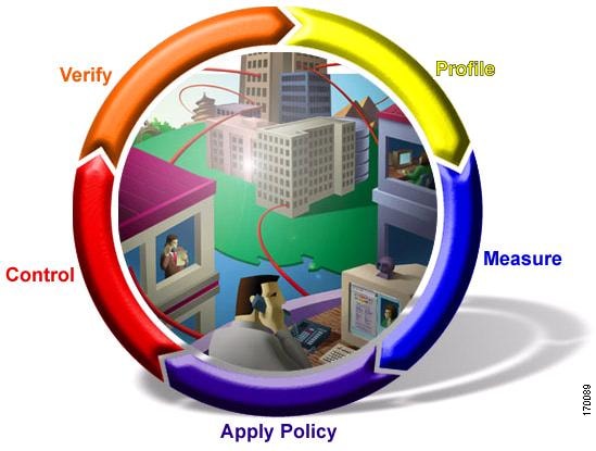
To introduce OER in your network you should understand and implement the following five OER phases:
The OER performance loop starts with the profile phase followed by the measure, apply policy, control, and verify phases. The flow continues after the verify phase back to the profile phase to update the traffic classes and cycle through the process.
OER Profile Phase
In medium to large networks there are hundreds of thousands of routes in the RIB to which a device is trying to route traffic. Because performance routing is a means of preferring some traffic over another, a subset of the total routes in the RIB has to be selected to optimize for performance routing. In the OER profile phase this selection of the subset of total traffic flowing through a device or a network is accomplished in a combination of ways:
•
•
OER Measure Phase
After you have profiled a group of traffic classes that are to be performance routed, the network has to measure the performance metrics of these individual traffic classes. There are two mechanisms—passive monitoring and active monitoring—to measure performance metrics, and one or both could be deployed in the network to accomplish this task. Monitoring is the act of measuring at periodic intervals.
Passive monitoring is the act of measuring the performance metrics of the traffic flow as the flow is traversing the device in the data path. Passive monitoring cannot be employed for measuring performance metrics for some traffic classes, and there are some hardware or software limitations.
Active monitoring consists of generating synthetic traffic to emulate the traffic class that is being monitored. The synthetic traffic is measured instead of the actual traffic class. Then the results of the synthetic traffic monitoring are applied to performance route the traffic class represented by the synthetic traffic.
You can also deploy both passive and active monitoring modes in an automated flow. The passive monitoring phase may detect traffic class performance that does not conform to an OER policy, and then active monitoring can be applied to that traffic class to find the best alternate performance path, if available. For more details about OER policies, see the "OER Apply Policy Phase" section.
OER Apply Policy Phase
After collecting the performance metrics of the class of traffic that you want to optimize, OER compares the results with a set of configured low and high thresholds for each metric. When a metric, and consequently a policy, goes out of bounds, it is an Out-of-Policy (OOP) event. The results are compared on a relative basis—a deviation from the observed mean—or on a threshold basis—the lower or upper bounds of a value—or a combination of both.
There are two types of policies that can be defined in OER: traffic class policies and link policies. Traffic class policies are defined for prefixes or for applications. Link policies are defined for exit or entrance links at the network edge. Both types of OER policies define the criteria for determining an OOP event. The policies are applied on a global basis in which a set of policies is applied to all traffic classes, or on a more targeted basis in which a set of policies is applied to a selected (filtered) list of traffic classes.
With multiple policies, many performance metric parameters, and different ways of assigning these policies to traffic classes, a method of resolving policy conflicts was created. The default arbitration method uses a default priority level given to each performance metric variable and each policy. You can configure different priority levels that overrides the default arbitration for all policies, or a selected set of policies.
OER Control Phase
In the OER control phase (also called the enforce phase) of the performance loop, the traffic is controlled to enhance the network performance time. The technique used to control the traffic depends on the class of traffic. For traffic classes that are defined using a prefix only, the prefix reachability information used in traditional routing can be manipulated. Protocols such as Border Gateway Protocol (BGP) or RIP are used to announce or remove the prefix reachability information by introducing or deleting a route and its appropriate cost metrics.
For traffic classes that are defined by an application in which a prefix and additional packet matching criteria are specified, OER cannot employ traditional routing protocols because routing protocols communicate the reachability of the prefix only. For these application traffic classes, OER uses two control methods: device specific and network specific.
The device specific control method is achieved using interaction with policy-based routing (PBR).
The network specific control method is achieved in two ways:
•
•
OER Verify Phase
During the OER control phase if a traffic class is OOP, then OER introduces controls to influence (optimize) the flow of the traffic for the traffic class that is OOP. A static route and a BGP route are examples of controls introduced by OER into the network. After the controls are introduced, OER will verify that the optimized traffic is flowing through the preferred exit or entrance links at the network edge. If the traffic class remains OOP, OER will drop the controls that were introduced to optimize the traffic for the OOP traffic class and cycle through the network performance loop.
OER and the Enterprise Network
Enterprise networks use multiple Internet Service Provider (ISP) or WAN connections at the network edge for reliability and load distribution. Existing reliability mechanisms depend on link state or route removal on the border router to select the best exit link for a prefix or set of prefixes. Multiple connections protect enterprise networks from catastrophic failures but do not protect the network from brownouts, or soft failures, that occur because of network congestion. Existing mechanisms can respond to catastrophic failures at the first indication of a problem. However, blackouts and brownouts can go undetected and often require the network operator to take action to resolve the problem. When a packet is transmitted between external networks (nationally or globally), the packet spends the vast majority of its life cycle on the WAN segments of the network. Optimizing WAN route selection in the enterprise network provides the end-user with the greatest performance improvement, even better than LAN speed improvements in the local network.
Although many of the examples used to describe OER deployment show ISPs as the network with which the edge devices communicate, there are other solutions. The network edge can be defined as any logical separation in a network: can be another part of the network such as a data center network within the same location, as well as WAN and ISP connections. The network, or part of the network, connected to the original network edge devices must have a separate autonomous system number when communicating using BGP.
OER is implemented in Cisco IOS software as an integrated part of Cisco core routing functionality. Deploying OER enables intelligent network traffic load distribution and dynamic failure detection for data paths at the network edge. While other routing mechanisms can provide both load distribution and failure mitigation, only OER can make routing adjustments based on criteria other than static routing metrics, such as response time, packet loss, path availability, and traffic load distribution. Deploying OER allows you to optimize network performance and link load utilization while minimizing bandwidth costs and reducing operational expenses.
The following two sections give an overview of a typical deployment of OER and the network components managed by OER:
•
Typical Deployment of OER
Figure 2 shows a typical OER-managed enterprise network of a content provider. The enterprise network has three exit interfaces that are used to deliver content to customer access networks. The content provider has a separate service level agreement (SLA) with a different ISP for each exit link. The customer access network has two edge routers that connect to the Internet. Traffic is carried between the enterprise network and the customer access network over six service provider (SP) networks.
Figure 2 A Typical OER Deployment
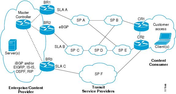
OER monitors and controls outbound traffic on the three border routers (BRs). In Cisco IOS Release 12.4(9)T, the ability to monitor and control inbound traffic was introduced. OER measures the packet response time and path availability from the egress interfaces on BR1, BR2 and BR3. Changes to exit link performance on the border routers are detected on a per-prefix basis. If the performance of a prefix falls below default or user-defined policy parameters, routing is altered locally in the enterprise network to optimize performance and to route around failure conditions that occur outside of the enterprise network. For example, an interface failure or network misconfiguration in the SP D network can cause outbound traffic that is carried over the BR2 exit interface to become congested or fail to reach the customer access network. Traditional routing mechanisms cannot anticipate or resolve these types of problems without intervention by the network operator. OER can detect failure conditions and automatically alter routing inside of the network to compensate.
Network Components Managed by OER
OER is configured on Cisco routers using Cisco IOS command-line interface (CLI) configurations. An OER deployment has two primary components, a master controller and one or more border routers. The master controller is the intelligent decision maker, while the border routers are enterprise edge routers with exit interfaces that are either used to access the Internet or used as WAN exit links.
OER Master Controller
The master controller is a single router that coordinates all OER functions within an OER-managed network. A Cisco router can be configured to run a standalone master controller process or can also be configured to perform other functions, such as routing or running a border router process. The master controller maintains communication and authenticates the sessions with the border routers. The master controller monitors outbound traffic flows using active or passive monitoring and then applies default or user-defined policies to alter routing to optimize prefixes and exit links. OER administration and control is centralized on the master controller, which makes all policy decisions and controls the border routers.
OER Border Router
The border router is an enterprise edge router with one or more exit links to an ISP or other participating network. The border router is where all policy decisions and changes to routing in the network are enforced. The border router participates in prefix monitoring and route optimization by reporting prefix and exit link measurements to the master controller and then by enforcing policy changes received from the master controller. The border router enforces policy changes by injecting a preferred route to alter routing in the network. The border router is deployed on the edge of the network, so the border router must be in the forwarding path. A border router process can be enabled on the same router as a master controller process.
OER-Managed Network Interfaces
An OER-managed network must have at least two egress interfaces that can carry outbound traffic and can be configured as external interfaces. These interfaces should connect to an ISP or WAN link (Frame-Relay, ATM) at the network edge. The router must also have one interface (reachable by the internal network) that can be configured as an internal interface for passive monitoring. There are three interface configurations required to deploy OER: external interfaces, internal interfaces, and local interfaces.
For more details about the master controller, border routers, and interfaces used by OER, see the "Setting Up OER Network Components" module.
Where to Go Next
If this is the first time you have read this document and you are ready to implement OER in your network, proceed to the "Setting Up OER Network Components" module. If you have set up your OER components, you should read through the other modules in the following order:
•
•
•
•
After you understand the various OER phases, review the OER solutions modules that are listed under "Related Documents" section.
Additional References
The following sections provide references related to Cisco IOS Optimized Edge Routing Overview.
Related Documents
Location of OER features
OER solution module: voice traffic optimization using OER active probes.
OER solution module: configuring VPN IPsec/GRE tunnel interfaces as OER-managed exit links.
"Configuring VPN IPsec/GRE Tunnel Interfaces As OER-Managed Exit Links" module
Cisco OER commands: complete command syntax, command mode, command history, defaults, usage guidelines and examples
•
•
OER CPU and memory performance test information
Cisco Optimized Edge Routing CPU and Memory Performance Tests
IP SLAs
Cisco IOS IP SLAs Configuration Guide, Release 12.4
Technical Assistance
Feature Information for Optimized Edge Routing Overview
Table 1 lists the features in this module and provides links to specific configuration information. Only features that were introduced or modified in Cisco IOS Releases 12.3(8)T, 12.2(33)SRB, or a later release appear in the table.
For information on a feature in this technology that is not documented here, see the "Cisco IOS Optimized Edge Routing Features Roadmap."
Not all commands may be available in your Cisco IOS software release. For release information about a specific command, see the command reference documentation.
Use Cisco Feature Navigator to find information about platform support and software image support. Cisco Feature Navigator enables you to determine which Cisco IOS and Catalyst OS software images support a specific software release, feature set, or platform. To access Cisco Feature Navigator, go to http://www.cisco.com/go/cfn. An account on Cisco.com is not required.

Note

Any Internet Protocol (IP) addresses used in this document are not intended to be actual addresses. Any examples, command display output, and figures included in the document are shown for illustrative purposes only. Any use of actual IP addresses in illustrative content is unintentional and coincidental.
© 2007 Cisco Systems, Inc. All rights reserved.