Cisco Nexus 9000 Clock Management
Available Languages
Bias-Free Language
The documentation set for this product strives to use bias-free language. For the purposes of this documentation set, bias-free is defined as language that does not imply discrimination based on age, disability, gender, racial identity, ethnic identity, sexual orientation, socioeconomic status, and intersectionality. Exceptions may be present in the documentation due to language that is hardcoded in the user interfaces of the product software, language used based on RFP documentation, or language that is used by a referenced third-party product. Learn more about how Cisco is using Inclusive Language.
- US/Canada 800-553-2447
- Worldwide Support Phone Numbers
- All Tools
 Feedback
 Feedback
 Legal Information
This document describes the working of Network Time Protocol (NTP), Precision Time Protocol (PTP), and Synchronous Ethernet (SyncE) with concepts, sample configurations, and troubleshooting scenarios for Cisco Nexus 9000 switches.
A clock for us is a wall clock or a wristwatch; but for networking devices, it is a periodic signal of alternate 0’s and 1’s which is used to sample the data bits. Just like the seconds hand in a clock has an angular movement to represent a second, a pair of 0 and 1 represents T (time period [T=1/frequency]). To generate this clock, network devices use a crystal oscillator which has a ±100 ppm (parts per million) error. For example, a clock with the frequency of 250 MHz and 100 ppm will have a frequency range of 249.975 MHz to 250.025 MHz in generating the clock signal. So, ideally, the clock is not completely periodic but is sufficient for the requirement of sampling the data signals out of the interfaces. All networks benefit from time synchronization. For more information, see Computer Network Time Synchronization.
Even if there is no strict time synchronization requirement for production applications running on a network, event correlation and root cause analysis is greatly improved by precise synchronization of network devices.
Types of Network Clock Synchronization
Frequency Synchronization
Frequency synchronization refers to the coordination of clock rates (the speed at which clocks tick) across different systems/components to ensure they operate at the same frequency. This concept is vital in various fields, including telecommunications, computer networks, and digital audio & video broadcasting, where different devices need to work together seamlessly.
Imagine two clocks ticking at different rates. Over time, these discrepancies can lead to significant drifts in the time reported by the two clocks. In systems that rely on precise timing, such as data transfer or signal processing, this can cause serious problems. Frequency synchronization ensures that all clocks in a system are ticking at the same rate, preventing such issues.
Phase synchronization is a fundamental concept in the field of physics and signal processing. It refers to the adjustment of the phase of an oscillating signal, such as a wave or a cycle, so that they align or synchronize with each other.
In a system of two or more interacting oscillators, phase synchronization occurs when the difference in their phases remains constant over time, even though their individual frequencies may not necessarily be the same. This means that the oscillators are effectively "dancing" in step with each other.
Time synchronization is the practice of coordinating clocks in a computer network to the same time. It's crucial for many aspects of system administration, data integrity, security, and digital forensics. Here are some of the principles of time synchronization:
● Coordinated Universal Time (UTC): This is the standard time reference used in time synchronization. It's critical that all devices in a network sync to UTC to ensure consistency across the system.
● Stratum Levels: Stratum levels indicate the distance from the reference clock. A stratum 0 device is a highly accurate timekeeping device such as an atomic clock. A stratum 1 device is a computer that receives time signals directly from a stratum 0 device, and so on. The stratum level impacts the accuracy of the time synchronization. Conversely, a stratum 16 clock is not synchronized and free-runs without an accurate time source.
● Clock Quality / Accuracy: This value is used to select the best source between PTP clocks dynamically, selecting the clock with greatest accuracy. Higher accuracy means the best source of real-time state.
● Precision: This refers to the accuracy of the time synchronization. More precise time synchronization requires more resources but can be necessary for certain applications.
● Synchronization Frequency: This refers to the amount of variance in time corrections, synchronization between clocks. More precise time synchronization requires more resources but can be necessary for certain applications. Precise time may not be accurate real-time, for instance if no external GPS clock source is available.
● Local Clocks: Every device in a network has a local clock that needs to be synchronized. This local clock can drift due to various factors, such as temperature changes or hardware limitations, so regular synchronization is necessary.
● Clocks Locked: A state where the system's clock is synchronized with an external reference clock, ensuring coordinated data processing and transfer. Typically, this is achieved using Phase-Locked Loop (PLL) or Delay Locked Loop (DLL) circuitry.
● Clock Recovery: The process of extracting timing information from a data stream, allowing the timing of the data in the stream to be accurately determined without separate clock information.
● Residence Time: End-to-end time to forward a synchronization frame through a device.
● Round Trip Time (RTT): This value is divided in half to assume latency in each direction.
Principles of Network Time Protocol
The Network Time Protocol (NTP) is a protocol used to synchronize the clocks of computers over an IP network. NTP was developed to solve the problem of multiple computers working together and needing to have synchronized time.
● Stratum Levels: NTP operates in a hierarchical manner, with multiple layers or "strata" of servers. At the top of the hierarchy (Stratum 0) are reference clocks, such as atomic clocks or GPS clocks, which provide the most accurate time. Stratum 1 servers are directly connected to Stratum 0 devices and are the next level of the hierarchy. They provide time to lower-stratum servers (Stratum 2, Stratum 3, etc.) and clients. The hierarchy allows the network to handle large numbers of clients while reducing the load on the Stratum 1 servers.
● Time Synchronization: NTP synchronizes time by exchanging time-stamped messages between the client and server. The client sends a message to the server, the server replies with a time-stamped message, and the client adjusts its clock based on the timestamps received.
● Clock Selection Algorithm: NTP uses a complex set of algorithms to determine the best and most reliable time source to use. It considers factors like network latency, jitter, and the stratum level of the servers.
● Clock Discipline Algorithm: This algorithm slowly adjusts the client's clock to avoid abrupt changes in time. It can adjust both the frequency and the offset (the difference between the local time and the server's time) of the clock.
● Fault Tolerance and Redundancy: NTP clients can be configured to synchronize with multiple servers. If one server becomes unreachable or is found to be unreliable, the client can switch to another server. This provides robustness and reliability in the time synchronization.
● Security: NTP includes some security features, like authentication, to prevent malicious attacks that could alter the time synchronization.
● Accuracy: NTP can achieve very high accuracy, often within a few milliseconds on the public Internet and even better in local area networks. NTP accuracy can be up to 50 milliseconds when residence time is high, which is not acceptable for high-performance applications such as video distribution or financial applications.
● UTC and Leap Seconds: NTP uses Coordinated Universal Time (UTC) as its time reference and has mechanisms to handle leap seconds (extra seconds added to UTC to keep it in sync with solar time).
Note: It is important to remember, the NTP protocol uses UDP/IP transport but does not support hardware assistance (hardware clock) to offset end-device delays including residence time. As a result, NTP is only accurate to a few milliseconds time synchronization (best case) and incapable of frequency or phase synchronization. Excessive variation in the one-way delay time negatively impacts synchronization accuracy.
NTP associations
● Peer Association: A device can either synchronize to another device or allow another device to synchronize to it.
● Server Association: A device synchronizes to a server. A server association presumes the association is to a lower stratum (more precise) clock.
NTP Clock Synchronization Algorithm
A typical NTP client regularly polls one or more NTP servers. The client must compute its time offset and round-trip delay. The time offset is passed through filters and analysis ("mitigation"). Outliers are discarded and an estimate of time offset is derived from the best three remaining candidates. The clock frequency is then adjusted to reduce the offset over time using so called "discipline" to prevent abrupt changes.
Accurate synchronization is achieved when both the incoming and outgoing routes between the client and the server have symmetrical delay. If the routes do not have a common delay, a systematic bias exists of half the difference between the forward and backward travel times.
NTP Access Restriction and Security
There have been several CVEs announced pertaining to NTP historically. NTP best practice is to ensure NX-OS is up to date with the latest security fixes, deploy NTP access-groups and/or NTP Authentication to protect NTP from malicious actors.
Please note that these are only a few of the recent CVEs and the list is not exhaustive. For a more exhaustive list based on your platform and software version, see the Cisco Security Adviser.
● CVE-2020-13817: In ntpd in NTP before 4.2.8p15 and 4.3.x before 4.3.101, an authenticated attacker can cause a NULL pointer dereference in ntpd, resulting in Denial of Service.
● CVE-2020-11868: In ntpd in NTP before 4.2.8p15 and 4.3.x before 4.3.101, a missing return statement in the receive() function can cause an authenticated peer to receive a response that was intended for another peer.
● CVE-2020-13857: In ntpd in NTP before 4.2.8p15 and 4.3.x before 4.3.101, a packet with a zero-origin timestamp and nonzero xmt (transmit) timestamp will bypass a test for a "valid" timestamp pair.
● CVE-2020-13858: In ntpd in NTP before 4.2.8p15 and 4.3.x before 4.3.101, a packet with a zero-origin timestamp and zero xmt (transmit) timestamp can cause a NULL pointer dereference, leading to Denial of Service.
Please reference the NTP configuration guide for more details.
configure terminal
ntp server 192.168.10.14 use-vrf management
ntp server 192.168.10.15 use-vrf management
rtp-arch07-sgbgw# show ntp peer-status
Total peers : 2
* - selected for sync, + - peer mode(active),
- - peer mode(passive), = - polled in client mode
remote local st poll reach delay vrf
--------------------------------------------------------------------------------------------
*192.168.10.15 0.0.0.0 1 64 377 0.00046 management
=192.168.10.14 0.0.0.0 1 64 377 0.00047 management
configure terminal
ntp source-interface mgmt0
ntp master 1
n9k-1# show ntp peer-status
Total peers : 1
* - selected for sync, + - peer mode(active),
- - peer mode(passive), = - polled in client mode
remote local st poll reach delay vrf
--------------------------------------------------------------------------------------------
*127.127.1.0 10.1.1.100 1 64 377 0.00000
Access groups will prevent the control-plane from communicating with unapproved NTP peer devices.
configure terminal
ip access-list approved-peers
10 permit ip 10.10.1.0/24 any
ntp access-group peer approved-peers
ntp access-group match-all
Authentication ensures approved peers are not spoofed.
configure terminal
ntp authenticate
ntp authentication-key 1 md5 iksgsr 7
n9k-1# show ntp authentication-status
Authentication enabled.
Principles of Precision Time Protocol
Precision Time Protocol (PTP) is an industry-standard protocol used to synchronize clocks in a computer network to a high degree of accuracy and precision. It is defined by the IEEE 1588-2008 standard.
The basic principle of PTP is to have one or more master clocks, which are the candidate reference time sources, and one or more slave clocks, which synchronize their time to the master. The selected master sends synchronization messages containing its current time to the slaves, and the slaves adjust their clocks based on the synchronization information from the elected master.
However, simply sending the master's time to the slaves doesn't guarantee precise synchronization due to inherent delay in network transmission of sync messages. This delay needs to be accounted for to achieve precise synchronization.
PTP uses a delay request-response mechanism where the slave sends a delay request to the master, the master responds with a delay response, and the slave measures the time it took for the round-trip. This round-trip delay is then used to correct the time received in the sync messages from the master.
In this way, PTP can synchronize clocks across a network with a precision of nanoseconds which is critical in many industries such as telecommunications, broadcasting, utilities and more. The exact precision and performance can vary based on the specific PTP profile used as well as the quality of the network and the clocks themselves. This mechanism along with the underlying hardware support allows PTP to hold much more precise time synchronization than NTP. With dedicated hardware support, PTP enabled can accurately measure the residence time between a PTP frame leaving the CPU and leaving the outgoing network interface.
The primary goal of PTP is to isolate the link delay and residence time for each hop in the network to understand a precise round-trip time and thus correction factor to synchronize a local clock to the elected grandmaster.
Main Principles of the PTP Protocol
● Precision: PTP is designed to provide very high precision clock synchronization. It can achieve sub-microsecond accuracy in local area networks under ideal conditions, which is more precise than NTP.
● PTP Domain: Defines a set of PTP enabled devices that will synchronize clocks from the elected grandmaster clock.
● Master-Slave Architecture: PTP operates in a master-slave architecture. The master clock sends synchronization messages to the slave clocks, which adjust their time based on these messages.
● Sync Message: Used by master to start a clock synchronization session with each slave.
● Delay Request-Delay Response Mechanism: To calculate the network delay, the slave clock sends a Delay_Request message to the master. The master responds with a Delay_Response message that contains the receipt time of the Delay_Request. This allows the slave to calculate the round-trip delay and adjust its clock accordingly.
● Best Master Clock Algorithm (BMCA): PTP uses the Best Master Clock Algorithm to automatically select the best master clock from a group of clocks. The BMCA considers factors such as clock accuracy and network path delay when selecting the best master clock.
● Timestamping: PTP uses hardware timestamping (when supported by the network hardware) to improve the precision of the time synchronization. The timestamp is applied when the packet is sent or received at the network interface, which reduces the impact of software and system delays.
● Profiles: PTP includes support for different "profiles" that adapt the protocol for different use cases. For example, the default profile is suitable for general-purpose networks, while other profiles are designed for specific industries or applications.
● Support for Synchronization of Time and Frequency: Unlike NTP, which only synchronizes time, PTP can also synchronize frequency, which is important in some applications.
Note: Nexus 9000 switches generally support PTP transport over UDP/IP while PTP over Ethernet is supported only on Cisco Nexus N9K-C9332D-H2R, N9K-C93400LD-H1, N9K-C9408, 93180YC-FX3 and N9K-C93180YC-FX3S platforms. PTP supports multicast as well as unicast communication with the configuration of unicast mode being optional. See the PTP Transport Options section below for more details.
PTP uses multicast destination IP address 224.0.1.129 as per IEEE 1588 standards for communication between devices. For the source IP address, it uses the user-configurable global IP address under the PTP domain. PTP multicast mode is only supported on physical interfaces for L2 or L3 interfaces. PTP multicast uses the Internetwork Control Block range.
For multicast PTP transport, use the PTP source address configuration rather than the local interface IP.
n9k-1 (config)# ptp source 10.10.10.20
Specifies the VLAN tag for the interface where PTP is being enabled. You can only enable PTP on one VLAN on an interface. In this example, VLAN 100 is selected.
n9k-1 (config-if)# ptp vlan 100
In unicast transport mode, PTP uses configurable unicast source and destination IP addresses that can be configured under an interface. Unicast mode is only supported on physical L3 interfaces. Although only physical interfaces are supported the source IP address can be derived from a logical interface assigned IP address (SVI or Loopback).
n9k-1(config-if)# ptp ucast-source 10.10.10.30
In both, the unicast and the multicast modes, PTP uses UDP ports, 319 for event messages and 320 for general messages communication between devices. By default, PTP running in unicast mode requires manual role assignment.
PTP unicast configuration is supported only under physical interface for L2 or L3 transport paths. However, PTP is supported with virtual interfaces such as Port-channel, SVI, and tunnel only when configured on associated physical interfaces. When PTP unicast is configured on L2/L3 Port-Channel members, the unicast source IP configuration is derived from the PTP VLAN SVI primary IP or L3 Port-Channel primary IP respectively.
N9k-1
interface Ethernet1/10
ptp
ptp transmission unicast
ptp role master
ptp slave 10.99.99.2
ptp ucast-source 10.99.99.1
ip address 10.99.99.1/24
N9k-2
interface Ethernet1/10
ptp
ptp transmission unicast
ptp role slave
ptp master 10.99.99.1
ptp ucast-source 10.99.99.2
ip address 10.99.99.2/24
Ethernet/L2 encapsulation mode is only supported using ITU PTP Profile. L2 transport mode (PTP over Ethernet) is not compatible with PTP over IP peers without translation. Only Nexus 9000 platforms which support ITU profile are capable of translation between PTP over Ethernet and traditional PTP over IP.
Note: Cisco Nexus N9K-C9332D-H2R, N9K-C93400LD-H1, N9K-C9408, 93180YC-FX3 and N9K-C93180YC-FX3S platforms support ITU profile SyncE/PTP.
A PTP enabled interface will transition between the following states according to the PTP interface state machine:
● Initialization: A PTP port is initializing when it first comes up and is in transient state
● Faulty: Indicates a protocol fault condition. A port in this state will not send PTP messages other than Management messages.
● Disabled: PTP disabled on the port. A port in this state will not send PTP messages other than Management messages.
● Listening: The PTP protocol is waiting for Announce Receipt Timeout to expire.
● Pre-Master: This is the same as Master state except that it shall not transmit any PTP related messages except for Pdelay_Req, Pdelay_Resp, Pdelay_Resp_Follow_Up, Signaling, or management messages that are a required response to a message received from the applicable management mechanism.
● Master: Port is providing time synchronization for downstream Slave. All PTP ports on the elected grandmaster switch that are up in steady state, are in Master state.
● Passive: In this state port will not transmit messages itself and will not respond to messages other than the PTP management messages. However, it will process all incoming Announce messages according to the rules of the BMCA. Redundant paths toward the grandmaster clock will be in a passive state.
● Uncalibrated: One or more PTP Ports in the Master state have been detected in the domain. The appropriate PTP Port in the Master state has been selected, and the local PTP Port is preparing to perform clock adjustments with respect to the selected PTP Port in the Master state.
● Slave: The Port is receiving time synchronization for the upstream Master. The PTP port is performing clock adjustments with respect to the selected PTP port in the Master state. It shall transmit any PTP message required by the protocol for the Slave state or any required response to a message received from the applicable management mechanism.
PTP messages are categorized into two separate categories, Event and General messages. Not all message types are required for PTP operation.
● Sync: Sent by the Master to distribute the time of day and start the synchronization session.
● Delay_Req: Sent by the Slave to the Master for end-to-end delay measurement (request-response delay mechanism).
● Pdelay_Req: Sent by link node A for peer-to-peer delay measurement (Not supported in NX-OS).
● Pdelay_Resp: Sent by link node B for peer-to-peer delay measurement (Not supported in NX-OS).
● Follow_Up: Sent by two-step clock Master following the sync message.
● Delay_Resp: Sent by primary for end-to-end delay measurement.
● Pdelay_Resp_FollowUp: Sent by link node B for peer-to-peer delay measurement (Not supported in NX-OS).
● Announce: Sent by the primary to establish a synchronization hierarchy. The Best Primary Clock Algorithm decides the best primary clock based on the clock properties in the announce message.
● Management: Sent by the management node to the clock for updating and querying the PTP datasets maintained by the clock. Management messages are optional depending on which PTP endpoint features are used.
● Signaling: Sent between peers for indication such as the unicast negotiation.
PTP Grandmaster Clock Election
A PTP Domain defines the scope of synchronization for the elected grandmaster clock (GM). The BMCA (Best Master Clock Algorithm) defines how a grandmaster clock is elected within the PTP domain. Below are the default parameters for BMCA as defined in IEEE 1588. Modification of these parameters may exist while running specific non-default PTP profiles.
● Default domain ID is 0
● All PTP nodes are synchronized to the elected grandmaster clock via a tree hierarchy
● Grandmaster clock identifier is derived from the device MAC Address
● After 3x Announce timeout will cause BMCA to re-run
● Announce Message caries BMCA parameters:
◦ Priority 1 (0-255) lower is better.
◦ Clock Accuracy (Set by Device) – Example: Locked on GPS, Class 6.
◦ Priority 2 (0-255) lower is better.
◦ MAC address of device (Tie Breaker).
In a Precision Time Protocol (PTP) system, nodes may have different roles to ensure accurate and synchronized time distribution across the network, these are the PTP roles:
● Grandmaster Clock (GMC): This is the primary reference clock in a PTP network. It generates the precise time that all other clocks in the system sync to. If a network has multiple grandmaster clocks, the one with the highest quality (based on factors like stability, accuracy, and priority settings) becomes the active grandmaster.
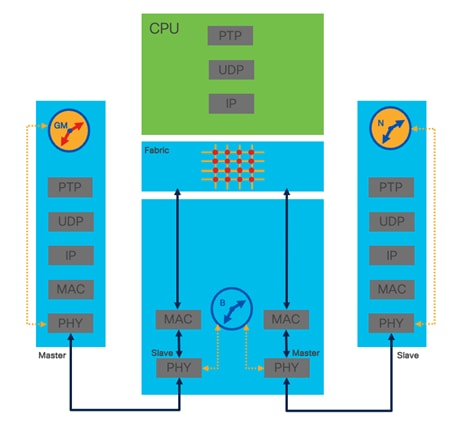
● Boundary Clock (BC): A boundary clock has both master and slave functionalities. It acts as a slave clock to its upstream master clock and as a master to its downstream clocks. This helps in reducing the number of sessions the grandmaster must maintain and can improve timing accuracy in larger networks. Boundary clocks can reduce the Delay_Request handling load on upstream master clocks, including grandmaster clock.
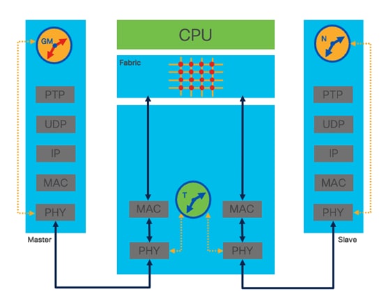
● Transparent Clock (TC): This type of clock measures the time a PTP event message takes to pass through the device and corrects the timestamp in the message to improve timing accuracy. Nexus 9000 switches do not support the transparent clock role.
● Ordinary Clock (OC): An ordinary clock has only a single PTP port. In a PTP system, an ordinary clock could be either a master or a slave device.
PTP clock roles are central in distributing precise time across the network. Nexus 9000 series switches support both PTP master and slave port roles. The PTP topology is computed using the elected grandmaster clock at the root of the PTP domain. Each subsequent PTP peer is represented by a Master/Slave relationship depending on its locality from the currently elected grandmaster. Slave ports recover a clock signal from master ports closer to the grandmaster clock.
Transparent clocks update their internal clocks based on PTP sync messages passing through the device without peering in the PTP control-plane. Transparent clocks can also update the Correction Factor (CF) field as Sync messages traverse the transparent switch.
The goal of transparent clock synchronization is to update residence time along the PTP session path without participating in the PTP peer control-plane explicitly.
Nexus 9000 Series switches run exclusively as boundary clocks. Switches, or other network devices, in the PTP path that do not participate in PTP will provide unaccounted sources of delay and jitter reducing the accuracy of the downstream clocks. Additionally, a larger number of boundary clocks in series, like any device, will lead to a tolerance “stack-up” effect where the small precision loss of each clock becomes additive across the PTP domain.
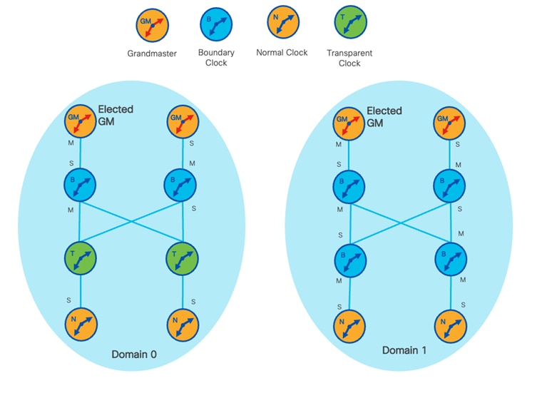
In the examples below we can see both normal and boundary elected grandmaster clocks distributing PTP messaging across the domain. Additionally, below are two separate PTP domains. In domain 0 the grandmaster clock is a normal clock (edge) and a switch in transparent operation is carrying the PTP sessions between the grandmaster and downstream boundary clocks.
Boundary Clock
Transparent Clock
Typical PTP Deployment - Comparison Boundary vs Transparent Clocks
PTP One-Step vs Two-Step PTP on Cisco Nexus Switches
Precision Time Protocol (PTP), defined in IEEE 1588, operates in the following two modes:
● One-step mode: In this mode, the master clock sends a single message (Sync) to the slave clock, which includes the precise time of transmission stamped by the hardware. The slave clock then uses this timestamp to adjust its own clock. This mode is simpler and faster because it only requires one message to be sent. However, it needs the master clock to be capable of generating the precise timestamp at the time of transmission.
● Two-step mode: In this mode, the master clock sends two separate messages. First, it sends a Sync message without a timestamp. Then, it follows up with a Follow_Up message that contains the precise timestamp. The master clock hardware can observe the sync message residence time and update precise timing using the Follow_Up. The two-step mode can increase the accuracy of time synchronization because the timestamp is generated after the Sync message is sent.
Note: The decision between one-step and two-step mode depends on the capability of the master clock, the participating slave clocks.
In two-step mode, the process is divided into the following two parts:
● Sync Message: The master clock sends a Sync message to the slave clocks. This message contains a sequence ID but does not contain the precise timestamp when the message was transmitted. Instead, it's used to indicate the beginning of a time interval.
● Follow_Up Message: After the Sync message, the master clock sends a Follow_Up message. This message contains the precise timestamp of when the Sync message was transmitted.
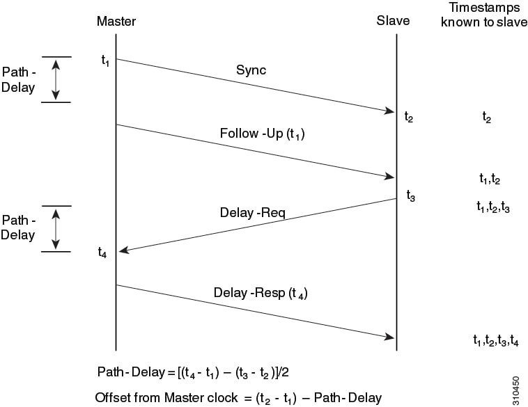
The advantage of this two-step mode is to enhance the precision of the timestamp exchange while simplifying the implementation. By splitting the process into two messages, PTP allows the master clock to take its time to precisely determine the timestamp for the Sync message. This is particularly useful in systems where generating the precise timestamp may take longer than the time it takes to send the message. All else being equal, two-step mode may reduce effective PTP port scale due to increased messaging overhead.
Nexus 9000 Cloud Scale based switches support offloaded two-step operation by default when enabled on Master ports facing downstream ordinary clocks. Cloud Scale supports one-step operation only on slave port and thus master/slave peering between Nexus Cloud Scale devices and upstream boundary or grandmaster clocks.
Nexus -R and -RX platforms support one-step mode when offloaded to the line card context. When a one-step operation is configured, offload is automatically enabled. Also note, that Ethanalyzer visibility into PTP messages is lost when offloaded to the line card CPU context. By default, a two-step operation is enabled on Master and Slave ports.
ptp offload
ptp clock-operation one-step
In summary, there is a performance tradeoff between message rate effective PTP port scale. One-step operation along with PTP timer values are two major factors impacting PTP scale and overall performance. However, in most cases a specific platform is required to run in either one-step or two-step operation, so message rates (timers) are the most effective lever to control messaging rate at scale.
Additionally, most external grandmaster clock implementations allow for either one-step or two-step operation and can be configured accordingly.
PTP profiles define a specific configuration of the PTP protocol that are designed for specific applications. They define a set of features and options to meet the precise timing requirements of a specific use case.
The standard PTP profile, also known as IEEE 1588, allows for many options with respect to messaging, transport protocol, network topology, etc. PTP profiles narrow down these options, providing a more specified and restricted version of the standard that is optimized for a certain type of application.
For example, the default PTP profile is intended for general purpose applications, while telecom profiles (ITU-T G.8275.1/2) are for telecommunication networks.
Each PTP profile includes specifications for parameters like clock accuracy, sync frequency, delay request-response mechanism, time source, and network protocols to be used. This allows for the precise synchronization of clocks in a network of devices, which is crucial in many industries such as telecommunications, power distribution, broadcasting, and more.
NX-OS supports default 1588, AES67, SMPTE 2059-2 and ITU profiles. They all have different ranges of sync and delay request intervals. For information on the default profile, refer to IEEE 1588. For more information on AES67 and SMPTE 2059-2, refer to the respective specifications.
Deploying an ITU profile comes with some specific caveats.
● The allowed domain number range for G.8275.1 profile is between 24 and 43. The default is 24. The allowed domain number range for G.8275.2 profile is between 44 and 63. Default is 44.
● ITU profiles implement an Alternate BMCA (Best Master Clock Algorithm) for grandmaster clock selection.
n9k-1(config)# ptp profile ?
8275-1 PTP telecom profile matching 8275.1
8275-2 PTP telecom profile matching 8275.2
default Default profile
PTP timers are described in terms of Log Mean Interval or the time in seconds until the next update interval. This approach allows users to interact with PTP enabled device in terms of integer values which equate to fractions of a second in operation of the PTP protocol stack. By reducing the LMI updates are sent more frequently thus reducing the local clock drifts from the grandmaster.
●  = 0.0625s or 16 packets per second
●  = 0.125s or 8 packets per second
●  = .25s or 4 packets per second
●  = .5s or 2 packets per second
●  = 32s or 1 packet in 32 seconds
●  = 64s or 1 packet in 64 seconds
Sync Interval Timer
| Option |
Range |
Default |
| aes67-2015 |
–4 to 5 log seconds |
-3 |
| smpte-2059-2 |
–4 to 5 log seconds |
-3 |
| Without the aes67-2015 or smpte-2059-2 option |
–1 to 6 log seconds (where –1 = 2 frames every second) |
● -2 log seconds
● -3 log seconds for Cisco Nexus 3232C, 3264Q, and 9500 platform switches
|
PTP and Port-Channels on Nexus Switches
Cisco Nexus switches do not support PTP configuration on port-channel logical interfaces however PTP can be configured on one or more member interfaces for redundancy. Whether configured for L2 or L3, port-channel members participating in PTP will use the configured PTP source, not the L3 port-channel IP address or SVI IP address carried by an L2 port-channel. On the slave side of the PTP peering a single link in the bundle will be in Slave state while the rest will remain Passive.
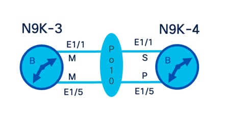
n9k-3# show ptp clock | grep Source
PTP Source IPv4 Address : 172.0.0.3
PTP Source IPv6 Address : 0::
n9k-3# show run interface ethernet 1/1, ethernet 1/5
!Command: show running-config interface Ethernet1/1, Ethernet1/5
!Running configuration last done at: Tue May 14 19:49:38 2024
!Time: Tue May 14 20:58:12 2024
version 10.5(1) Bios:version 01.10
interface Ethernet1/1
ptp
mtu 9216
channel-group 10 mode active
no shutdown
interface Ethernet1/5
ptp
mtu 9216
channel-group 10 mode active
no shutdown
n9k-3# show port-channel summary
Flags: D - Down P - Up in port-channel (members)
I - Individual H - Hot-standby (LACP only)
s - Suspended r - Module-removed
b - BFD Session Wait
S - Switched R - Routed
U - Up (port-channel)
p - Up in delay-lacp mode (member)
M - Not in use. Min-links not met
--------------------------------------------------------------------------------
Group Port- Type Protocol Member Ports
Channel
--------------------------------------------------------------------------------
10 Po10(SU) Eth LACP Eth1/1(P) Eth1/5(P)
n9k-3# show ptp brief
PTP port status
--------------------------------------------
Port State
------------------------------- ------------
Eth1/1 Master
Eth1/5 Master
n9k-3# run bash
bash-4.4$ sudo tcpdump -i Eth1-1 "udp"
tcpdump: verbose output suppressed, use -v or -vv for full protocol decode
listening on Eth1-1, link-type EN10MB (Ethernet), capture size 262144 bytes
18:23:52.527014 IP 172.0.0.3.319 > 224.0.1.129.319: UDP, length 44
18:23:52.777320 IP 172.0.0.3.319 > 224.0.1.129.319: UDP, length 44
18:23:53.027943 IP 172.0.0.3.319 > 224.0.1.129.319: UDP, length 44
18:23:53.183710 IP 172.0.0.3.320 > 224.0.1.129.320: UDP, length 64
18:23:53.278244 IP 172.0.0.3.319 > 224.0.1.129.319: UDP, length 44
18:23:53.529142 IP 172.0.0.3.319 > 224.0.1.129.319: UDP, length 44
n9k-4# show ptp clock | grep Source
PTP Source IPv4 Address : 172.0.0.4
PTP Source IPv6 Address : 0::
n9k-4# show run interface ethernet 1/1, ethernet 1/5
!Command: show running-config interface Ethernet1/1, Ethernet1/5
!Running configuration last done at: Wed May 15 18:14:05 2024
!Time: Wed May 15 19:25:31 2024
version 10.5(1) Bios:version 01.10
interface Ethernet1/1
ptp
mtu 9216
channel-group 10 mode active
no shutdown
interface Ethernet1/5
ptp
mtu 9216
channel-group 10 mode active
no shutdown
n9k-4# show port-channel summary
Flags: D - Down P - Up in port-channel (members)
I - Individual H - Hot-standby (LACP only)
s - Suspended r - Module-removed
b - BFD Session Wait
S - Switched R - Routed
U - Up (port-channel)
p - Up in delay-lacp mode (member)
M - Not in use. Min-links not met
--------------------------------------------------------------------------------
Group Port- Type Protocol Member Ports
Channel
--------------------------------------------------------------------------------
10 Po10(SU) Eth LACP Eth1/1(P) Eth1/5(P)
n9k-4# show ptp brief
PTP port status
--------------------------------------------
Port State
------------------------------- ------------
Eth1/1 Slave
Eth1/5 Passive
PTP Boundary Clock & Generalized PTP Configuration
By default, Cisco Nexus switches operate in boundary-clock mode.
n9k-2(config)# ptp device-type ?
boundary-clock Boundary-clock
generalized-ptp Generalized PTP
Generalized precision time protocol (PTP) is an IEEE 802.1AS standard that provides a mechanism to synchronize the clocks of the bridges and end-point devices in a network. Generalized PTP defines the mechanism to elect the grandmaster clock (using the Best Master Clock Algorithm [BMCA]) among the time-aware bridges and the talker and listener.
PTP and GPS/GNSS on Nexus 9000
Beginning with Cisco NX-OS Release 10.3(2)F, the GPS input is supported only on the Cisco Nexus 93180YC-FX3 switch with the following limitations.
The GNSS receiver is designed to operate on the GPS, Galileo, GLONASS, BeiDou and QZSS L1 frequencies 1551MHz to 1614MHz, standard position service, and Coarse Acquisition code. When connected to an external GNSS antenna, the receiver contains all the circuitry necessary to automatically acquire GNSS satellite signals, track up to 32 GNSS satellites, and compute location, speed, heading, and time. It provides an accurate one pulse-per-second (PPS) and stable 10-MHz frequency output for internal system use.
clock protocol gnss
gnss-receiver sync 1/2
frequency synchronization
selection input
wait-to-restore 0
no shutdown
Cisco Nexus 9000 Switches as a PTP Grandmaster Clock
Nexus 9000 series switches can simultaneously operate as a Boundary Clock and a Grandmaster clock. A high-precision oscillator is required to operate as a stable grandmaster clock. Nexus 9000 93180YC-FX3 or N9K-C93180YC-FX3S hardware is capable of both the boundary clock function and high precision oscillator for stable grandmaster clock operation.
Starting in 10.3(2)F, the ordinary clock grandmaster is available only for Cisco Nexus N9K-C93180YC-FX3 or N9K-C93180YC-FX3S platform.
ptp device-type [generalized-ptp | boundary-clock | ordinary-clock-grandmaster]
Operating a Nexus 9000 switch as an ordinary grandmaster clock will ensure PTP ports are in the master role, or else a role mismatch is detected.
This feature allows BMCA to select roles dynamically as follows, rather than assigning static roles:
· Use the ptp peer
· Port remains in a Listening state until the Peer IP is reachable when it transitions to the Master state.
· Announce packets are sent as soon as the peer is reachable.
· Based on Announce packet (using BMCA), the Role will be decided. Port state transitions accordingly.
Isolating a PTP Nexus 9000 Boundary Clock
An NX-OS PTP boundary clock can be configured to isolate downstream clocks.
PTP Role Enforcement in Multicast Transport Mode
NX-OS allows users to force PTP port role master per PTP interface while configured for multicast transport mode. This can be helpful in preventing a PTP port from transitioning into an undesired state and thus deriving synchronization from an inferior source. Use role enforcement when connecting Nexus switches to untrusted PTP edge devices or mitigating inadvertent role transition corner cases. Specifically unreliable PTP domain edge Boundary Clocks can be configured for static role assignment to harden the PTP domain.
n9k-3# show run interface e1/1
!Command: show running-config interface Ethernet1/1
!Running configuration last done at: Thu May 16 20:07:35 2024
!Time: Thu May 16 20:07:56 2024
version 10.5(1) Bios:version 01.10
interface Ethernet1/1
ptp
ptp role master
switchport
switchport mode trunk
channel-group 10 mode active
no shutdown
Disabling PTP Management Message Propagation
Management messages can be disabled using the following command. By enabling the PTP feature and disabling management messages, they will be consumed by software and not forwarded to downstream PTP slave devices.
switch(config)# no ptp management
As Management Messages are optional, given deployment specifics, there may be reasons to prevent erroneous or unwanted managed queries within the PTP domain. These unwanted PTP Management Messages can consume hardware CoPP policer thresholds causing inadvertent PTP drops and high correction oscillations.
Some customers may want to block PTP management messages using hardware user defined ACLs. By blocking in the hardware path, these messages will be dropped prior to CoPP accounting. PTP management ACLs require user defined ACL qualifier carved in hardware forwarding. Additionally, be advised that fixed UDF packet-start offset will change depending on ingress interface encapsulation, such as dot1q tagging.
udf ptp-management packet-start 42 1
hardware access-list tcam region ing-racl 1024
hardware access-list tcam region ing-racl qualify udf ptp-management
ip access-list PTP_MANAGEMENT_BLOCK
statistics per-entry
100 remark deny ptp management packets from all sources
101 deny ip any 224.0.1.129/32 udf ptp-management 0xd 0xff
200 remark permit any other PTP messages and ICMP echo
201 permit ip any 224.0.1.129/32
202 permit ip any 224.0.0.107/32
203 permit icmp any any echo
204 permit icmp any any echo-reply
ip access-list PTP_MANAGEMENT_GM_ONLY
statistics per-entry
10 remark allow ptp management packets from master clocks
11 permit ip 10.10.252.2/32 224.0.1.129/32 udf ptp-management 0xd 0xff
12 permit ip 10.10.252.10/32 224.0.1.129/32 udf ptp-management 0xd 0xff
13 permit ip 10.10.254.2/32 224.0.1.129/32 udf ptp-management 0xd 0xff
14 permit ip 10.10.254.10/32 224.0.1.129/32 udf ptp-management 0xd 0xff
100 remark deny management packets from all other sources
101 deny ip any 224.0.1.129/32 udf ptp-management 0xd 0xff
200 remark permit any other ptp messages and ICMP echo
201 permit ip any 224.0.1.129/32
202 permit ip any 224.0.0.107/32
203 permit icmp any any echo
204 permit icmp any any echo-reply
Multicast Environment Stability
When PTP is deployed using multicast transport the stability of the PTP domain is dependent on the underlying multicast routing for reachability. Ensure all switches within the PTP domain have the PTP feature enabled for proper handling of Internetwork Control Block addresses assigned to PTP. If PTP is disabled on a transit Nexus device in the PTP domain, point-to-point PTP messages will be flooded to indirectly connected PTP devices causing disruption to the PTP domain.
Tuning Control-Plane Policing for PTP Scale
Control-Plane Policing (CoPP) is a feature on Cisco Nexus switches that allows users to limit and control the traffic rate of certain protocols processing on the CPU, including PTP.
The default PTP policer (280 kbps) is not sufficient for large scale PTP domain scale. Depending on the number of PTP speakers, one-step vs two-step operation, and other factors such as PTP profile, CoPP will require tuning for PTP to operate nominally.
Consult the PTP supported scale for your platform and NX-OS version to understand the maximum verified scale. In a typical 64 ports PTP switch configuration, with a ‘-3’ update interval, a two-step operation (8 x 4, including 8 management) will average 2304 packets per second. At a typical 80 bytes per frame with 20% overhead, ~1769 kbps.
Monitor the CoPP System class and verify drops are not occurring; generally one of the first steps in validating PTP domain stability.
Default Strict CoPP Policy for PTP contained class:
ip access-list copp-system-p-acl-ptp
permit udp any 224.0.1.129/32 eq 319
permit udp any 224.0.1.129/32 eq 320
mac access-list copp-system-p-acl-ptp-l2
permit any any 0x88f7
ip access-list copp-system-p-acl-ptp-uc
permit udp any any eq 319
permit udp any any eq 320
ipv6 access-list copp-system-p-acl-ptpv6
permit udp any ff02::181/128 eq 319
permit udp any ff02::181/128 eq 320
ipv6 access-list copp-system-p-acl-ptpv6-uc
permit udp any any eq 319
permit udp any any eq 320
class-map type control-plane match-any copp-system-p-class-redirect
match access-group name copp-system-p-acl-ptp
match access-group name copp-system-p-acl-ptpv6
match access-group name copp-system-p-acl-ptp-l2
match access-group name copp-system-p-acl-ptp-uc
match access-group name copp-system-p-acl-ptpv6-uc
class copp-system-p-class-redirect
set cos 1
police cir 280 kbps bc 32000 bytes conform transmit violate drop
The NX-OS guide to tune CoPP on Nexus 9000
Note: Remember, CoPP should be configured according to your specific network requirements and the above is just a general guide. If you're not sure about the correct settings, you should contact support for assistance.
Starting in NX-OS 10.5(1)F the default CoPP policy has been increased to accommodate larger PTP scale. This does not eliminate the need for CoPP tuning under all circumstances but reduces the need in many typical PTP deployments.
class-map type control-plane match-any copp-system-p-class-redirect
match access-group name copp-system-p-acl-ptp
match access-group name copp-system-p-acl-ptp-l2
match access-group name copp-system-p-acl-ptp-uc
class copp-system-p-class-redirect
set cos 1
police cir 1800 kbps bc 32000 bytes conform transmit violate drop
When operating a Nexus switch in high PTP client scale mode CoPP should be tuned accordingly, as well as disabling PTP debugs. The following command allows 64 peers per supported ToR and 64 peers per line card on the supported EoR chassis. Consult the PTP scale supported for your platform and NX-OS version to understand the maximum verified scale. This feature is to be used only in specific deployment scenarios where higher scaling of PTP multicast secondary devices is required even though the ability to debug is very limited.
ptp enhanced-client-scale
To achieve the lowest correction jitter, ensure the PTP slave port does not share a hardware MAC instance with downstream devices. Additionally, enable no more than two PTP master ports per hardware MAC. This is not a requirement per full-scale SMPTE or ITU profiles, however, can be used to further optimize correction jitter performance.
The hardware MAC for ports on any given switch can be checked using the following command:
In this example on C93360YC-FX2, the following highlighted ports share MAC instance 24:
show interface hardware-mappings
n9k-fx2# show interface hardware-mappings
Legends:
SMod - Source Mod. 0 is N/A
Unit - Unit on which port resides. N/A for port channels
HPort - Hardware Port Number or Hardware Trunk Id:
HName - Hardware port name. None means N/A
FPort - Fabric facing port number. 255 means N/A
NPort - Front panel port number
VPort - Virtual Port Number. -1 means N/A
Slice - Slice Number. N/A for BCM systems
SPort - Port Number wrt Slice. N/A for BCM systems
SrcId - Source Id Number. N/A for BCM systems
MacIdx - Mac index. N/A for BCM systems
MacSubPort - Mac sub port. N/A for BCM systems
Ifg - Interface Group
InFPort - Internal Front port number.
---------------------------------------------------------------------------------------------------------------------------------------------
Name Ifindex Smod Unit HPort FPort NPort VPort SliceSPort SrcId MacId MacSP VIF Block BlkSrcID
--------------------------------------------------------------------------------------------
Eth1/1 1a000000 1 0 99 255 0 -1 1 27 54 24 6 1 0 54
Eth1/2 1a000200 1 0 98 255 4 -1 1 26 52 24 4 5 0 52
Eth1/3 1a000400 1 0 102 255 8 -1 1 30 60 25 4 9 0 60
Eth1/4 1a000600 1 0 103 255 12 -1 1 31 62 25 6 13 0 62
Eth1/5 1a000800 1 0 106 255 16 -1 1 34 68 26 4 17 0 68
Eth1/6 1a000a00 1 0 107 255 20 -1 1 35 70 26 6 21 0 70
Eth1/7 1a000c00 1 0 110 255 24 -1 1 38 76 27 4 25 1 4
Eth1/8 1a000e00 1 0 111 255 28 -1 1 39 78 27 6 29 1 6
Eth1/9 1a001000 1 0 115 255 32 -1 1 43 86 28 6 33 1 14
Eth1/10 1a001200 1 0 114 255 36 -1 1 42 84 28 4 37 1 12 Eth1/11 1a001400 1 0 119 255 40 -1 1 47 94 29 6 41 1 22
Eth1/12 1a001600 1 0 118 255 44 -1 1 46 92 29 4 45 1 20
Eth1/13 1a001800 1 0 122 255 48 -1 1 50 100 30 4 49 1 28
Eth1/14 1a001a00 1 0 123 255 52 -1 1 51 102 30 6 53 1 30
Eth1/15 1a001c00 1 0 126 255 56 -1 1 54 108 31 4 57 1 36
Eth1/16 1a001e00 1 0 127 255 60 -1 1 55 110 31 6 61 1 38
Eth1/17 1a002000 1 0 130 255 64 -1 1 58 116 32 4 65 1 44
Eth1/18 1a002200 1 0 131 255 68 -1 1 59 118 32 6 69 1 46
Eth1/19 1a002400 1 0 134 255 72 -1 1 62 124 33 4 73 1 52
Eth1/20 1a002600 1 0 135 255 76 -1 1 63 126 33 6 77 1 54
Eth1/21 1a002800 1 0 138 255 80 -1 1 66 132 34 4 81 1 60
Eth1/22 1a002a00 1 0 139 255 84 -1 1 67 134 34 6 85 1 62
Eth1/23 1a002c00 1 0 142 255 88 -1 1 70 140 35 4 89 1 68
Eth1/24 1a002e00 1 0 143 255 92 -1 1 71 142 35 6 93 1 70
Eth1/25 1a003000 1 0 71 255 96 -1 0 71 142 17 6 97 1 70
Eth1/26 1a003200 1 0 70 255 100 -1 0 70 140 17 4 101 1 68
Eth1/27 1a003400 1 0 67 255 104 -1 0 67 134 16 6 105 1 62
Eth1/28 1a003600 1 0 66 255 108 -1 0 66 132 16 4 109 1 60
Eth1/29 1a003800 1 0 63 255 112 -1 0 63 126 15 6 113 1 54
Eth1/30 1a003a00 1 0 62 255 116 -1 0 62 124 15 4 117 1 52
Eth1/31 1a003c00 1 0 58 255 120 -1 0 58 116 14 4 121 1 44
Eth1/32 1a003e00 1 0 59 255 124 -1 0 59 118 14 6 125 1 46
Eth1/33 1a004000 1 0 54 255 128 -1 0 54 108 13 4 129 1 36
Eth1/34 1a004200 1 0 55 255 132 -1 0 55 110 13 6 133 1 38
Eth1/35 1a004400 1 0 50 255 136 -1 0 50 100 12 4 137 1 28
Eth1/36 1a004600 1 0 51 255 140 -1 0 51 102 12 6 141 1 30
Eth1/37 1a004800 1 0 47 255 144 -1 0 47 94 11 6 145 1 22
Eth1/38 1a004a00 1 0 46 255 148 -1 0 46 92 11 4 149 1 20
Eth1/39 1a004c00 1 0 42 255 152 -1 0 42 84 10 4 153 1 12
Eth1/40 1a004e00 1 0 43 255 156 -1 0 43 86 10 6 157 1 14
Eth1/41 1a005000 1 0 39 255 160 -1 0 39 78 9 6 161 1 6
Eth1/42 1a005200 1 0 38 255 164 -1 0 38 76 9 4 165 1 4
Eth1/43 1a005400 1 0 35 255 168 -1 0 35 70 8 6 169 0 70
Eth1/44 1a005600 1 0 34 255 172 -1 0 34 68 8 4 173 0 68
Eth1/45 1a005800 1 0 31 255 176 -1 0 31 62 7 6 177 0 62
Eth1/46 1a005a00 1 0 30 255 180 -1 0 30 60 7 4 181 0 60
Eth1/47 1a005c00 1 0 27 255 184 -1 0 27 54 6 6 185 0 54
n9k-1(config)# ptp scale-on-1g
This feature enables PTP timestamping in the Forwarding ASIC’s MAC block vs default PHY for specific supported platforms. For 93108TC-FX3P, up to 25 1G PTP interfaces are supported without enabling enhanced scale 1G scale. Once enhanced 1G scale mode is configured, interface PTP timestamping will be performed on the forwarding engine ASIC for 1G ports allowing full downlink port scale at 1G.
PTP Boundary Clock Reload Events
In a stable PTP network, after any PTP node reloads, the local PTP clock will be synced to its Parent (GM). During this process a local PTP node may have significant correction while correcting its local clock. Transiently it may propagate erratic time to downstream PTP devices. This can cause excessive corrections for all downstream nodes until the reloaded devices synchronizes its own clock.
Starting in 10.4(4) and 10.5(1) Nexus 9000 boundary clocks support a new feature that provides a hold-down time to allow the local clock to synchronize before distributing time to downstream devices. The command ptp time distribution-hold can be used to hold-down PTP time propagation to downstream devices until a time or correction threshold limit is achieved, thus mitigating a ripple effect of correction events during a boundary clock reload.
syntax [no] ptp time distribution-hold [ correction-threshold <corr_limit> ] [ delay-threshold <max_delay_time> ]
keyword distribution-hold "Hold the time distribution"
keyword correction-threshold "Hold the time distribution till the correction settles down to a specified threshold"
integer <corr_limit> "Absolute Correction threshold value in nanoseconds" 1 100000
keyword delay-threshold "Set the maximum time limit for to hold the time-distribution"
PTP Grandmaster Switchover Events
Multiple candidate grandmaster clocks can exist in each PTP domain but only one is selected as the elected grandmaster clock. During a grandmaster election, either during initial setup or grandmaster failover events from link failures or device failures, there is a period where individual device’s clock must “free-run” and can drift. This can cause a transient loss in clock precision throughout the PTP domain.
An optimization can be designed to allow fallback to high precision “feeder” switches during the period during grandmaster elections. These feeder switches, such as Nexus 93180YC-FX3, contain high precision oscillators, just like elected grandmaster clocks. This will reduce transient jitter during re-election events.
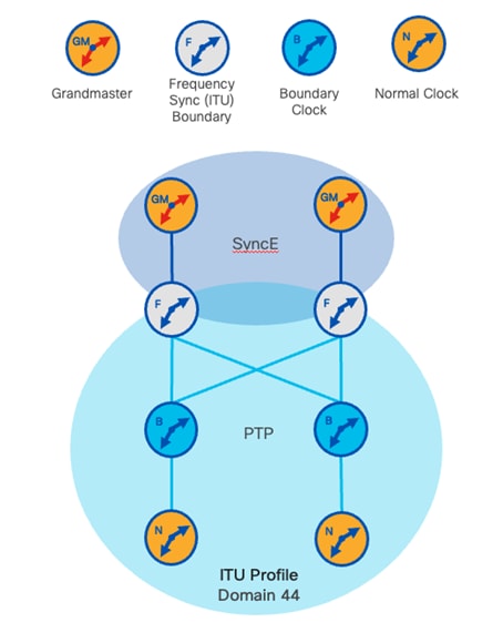
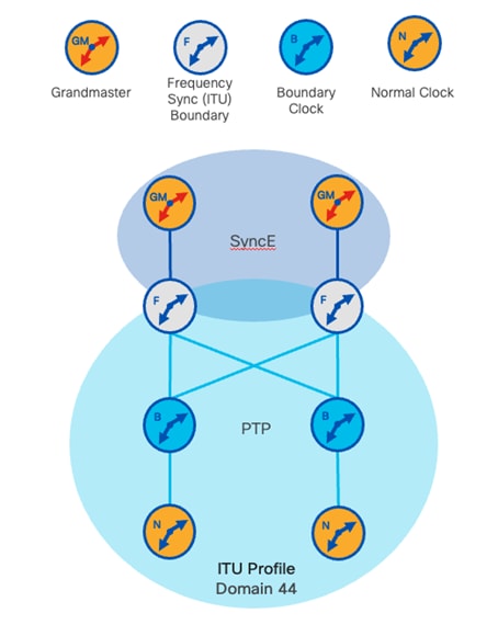
Only Cisco Nexus N9K-C9332D-H2R, N9K-C93400LD-H1, N9K-C9408, 93180YC-FX3, N9K-C93180YC-FX3S platform switches using ITU profile can take advantage of high precision DPLL oscillators. These grandmaster clock quality oscillators can maintain high stability while free running during grandmaster convergence events. Additionally, frequency synchronization capable switches can translate between SyncE and PTP over IP. This requires PTP to operate using the ITU profile along with the associated requirements, such as ITU profile valid domain IDs.
n9k-1# show run fsync_mgr
!Command: show running-config fsync_mgr
!Running configuration last done at: Fri Jun 7 20:03:40 2024
!Time: Wed Jun 12 18:09:43 2024
version 10.5(1) Bios:version 01.10
feature frequency-synchronization
n9k-1# show frequency synchronization clock-interface detail
Clock interface Internal0 (Up)
Assigned as input for selection
Input:
Default QL: None
Effective QL: Opt-I/SEC, Priority: 255
Supports frequency
Next selection points:System Clock (T0) Selector, IEEE 1588 Clock Selector,
Note: Starting in NX-OS 10.5(2), N9K-C93180YC-FX3 and N9K-C93180YC-FX3S switches using SMPTE profile can act as a high quality “feeder” PTP switch capable of maintaining high PTP clock precision during grandmaster switchover events. Due to additional improvements in DPLL management it is suggested to run NX-OS 10.5(7), 10.6(4) or later, on N9K-C93180YC-FX3 and N9K-C93180YC-FX3S switches, when configured for SMPTE or ITU profiles.
Synchronous Ethernet (SyncE) is a method for distributing a clock signal through an Ethernet network. The goal of SyncE is to enable Ethernet networks to carry synchronized clock signals which are necessary for time-sensitive applications like voice and video services.
The principle of SyncE is based on the traditional Ethernet physical layer but it adds a clock signal into the Ethernet scheme. In other words, SyncE extends the functionality of Ethernet by adding the ability to deliver a clock signal from one end of the network to the other thus emulating clocking distribution in a legacy TDM network.
The clock source sends its timing information to the Ethernet equipment, which then embeds the clock signal into the Ethernet data stream. This clock signal is then propagated throughout the network, allowing all the devices on the network to synchronize their clocks to the same reference clock.
This synchronization is crucial for many applications, particularly in telecommunications and networking, where precise timing is required across multiple devices. It ensures that data packets are transmitted and received at the correct times, reducing jitter, and improving the quality of service. It's important to note that SyncE only provides frequency synchronization, not time-of-day synchronization. For full time and phase synchronization, SyncE is often used in combination with PTP.
Starting in NX-OS 9.3(5) on Nexus 93180YC-FX3 or N9K-C93180YC-FX3S a PTP/SyncE hybrid solution is available to provide an end-to-end synchronization solution.
Profile Default: mode { hybrid | non-hybrid | none }
Example:
switch(config-ptp-profile)#
switch(config)# mode hybrid
Configures the PTP operational mode for the switch:
hybrid: The SyncE source acts as the PTP source.
default: The local/1588 clock acts as the PTP source.
· This command is automatically configured when the ptp profile command is set. The configuration value cannot be changed.
· The only mode that the 8275-2 profile supports is non-hybrid.
· The profile default mode is hybrid.
Relationship between PTP and SyncE
PTP (IEEE 1588) is a protocol used to synchronize clocks throughout a computer network to a high degree of accuracy and precision. PTP can provide sub-microsecond synchronization, making it suitable for applications that require very precise timing. However, PTP distributes time-of-day information, but not a continuous synchronization signal.
SyncE, on the other hand, is an Ethernet-based synchronization standard. It provides a method for transmitting a continuous synchronization signal over the physical layer of the Ethernet network. SyncE can provide frequency synchronization, but not time-of-day or phase synchronization.
PTP and SyncE is that they can work together to provide comprehensive time and frequency synchronization in a network.
While PTP is used for phase and time-of-day synchronization. The combination of SyncE and PTP can provide the accurate and reliable synchronization needed for many time-sensitive applications.
In this combined model, SyncE helps to stabilize the frequency of the local oscillator of the network devices, reducing the amount of phase variation that PTP must compensate for, resulting in better overall synchronization performance.
SyncE operation of PTP over Ethernet cannot interop with PTP over IP, unicast, or multicast mode, without conversion. A Nexus 93180YC-FX3 or N9K-C93180YC-FX3S can operate as both PTP over Ethernet and PTP over IP modes and translate between PTP transport methods.
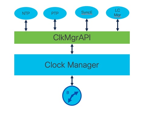
Multiple clock synchronization protocols along with multiple hardware clocks can exist on a single Nexus switch. The Clock Manager software component is designed to abstract hardware clocks from individual synchronization protocols to allow multiple protocols to coexist at once. Clocks are resources that need to be shared across different processes and across different VDCs. Thus, we require an arbitrator that chooses just one time synchronization protocol instance at a given time whose inputs should be used to control the various clocks in the system. In the case where no time synchronization protocol instance is running, we still perform intra-chassis synchronization and syntonization so that latency measurement protocols can get accurate results.
Users configure the “clock controller” responsible for synchronizing clocks across the system. For instance, you may want PTP to be the clock controller while running NTP to distribute clocking across your network environment.
Specify the desired clock protocol to be primary on Nexus 9000
n9k-1(config)# clock protocol ?
none None (clock can be set manually)
ntp Network Time Protocol (NTP)
ptp Precision Time Protocol (PTP)
n9k-1# show clock
03:31:25.149 UTC Thu Feb 08 2024
Time source is NTP
N9k-1# clock protocol ntp
N9k-1# show system internal clk_mgr info all
Global info:
Clock Protocol : NTP
Next Clock Protocol : NTP
VDC ID for Clock Protocol : 1
Next VDC ID for Clock Protocol : 1
PTP capable LC slots :
Reference port / Slave i/f :
PTP freq adjustment (test) : Enabled
Reference port / Slave i/f (FSM) :
Reference port / Slave i/f if_index : 0x0
Previous Reference port / Slave i/f :
Reference port / Slave i/f Card ID : 0
ERSPAN granularity : 0 (100 MS)
PTP UTC Offset : 0
N9k-2# clock protocol ptp
N9k-2# show system internal clk_mgr info all
Global info:
Clock Protocol : PTP
Next Clock Protocol : PTP
VDC ID for Clock Protocol : 1
Next VDC ID for Clock Protocol : 1
PTP capable LC slots :
Reference port / Slave i/f :
PTP freq adjustment (test) : Enabled
Reference port / Slave i/f (FSM) :
Reference port / Slave i/f if_index : 0x0
Previous Reference port / Slave i/f :
Reference port / Slave i/f Card ID : 0
ERSPAN granularity : 0 (100 MS)
PTP UTC Offset : 0
Generally, enabling NTP and PTP simultaneously is not recommended on Nexus 9000 switches. If a user wants to run PTP, configure clock protocol ptp. If a user runs NTP, configure clock protocol ntp. In more recent NX-OS releases, this limitation was relaxed to allow a Nexus 9000 switch to operate as a “low grade” grandmaster clock for specific applications. In this case external time is derived from NTP, while PTP is used to synchronize devices within the PTP domain. This eliminates the need for an external GPS or 10-Mhz clock source when this is not required. See the PTP as grandmaster section below. The expectation is that NTP is disciplining the local clock for PTP GM functionality rather than running NTP and PTP in a “ships in the night” configuration.
When PTP clock source (i.e Master) connectivity is disconnected, it's difficult for slaves (acting as master for other downstream slaves in the network) to synchronize time. To overcome this problem, system clock time can be fed to PTP slave for it to propagate/sync to its slaves. See the next section for more details.
Additionally, when a GNSS source is configured for PTP grandmaster configuration, the clock protocol should be set to GNSS.
clock protocol gnss
Nexus 9000 Switches as PTP Grandmaster with Cisco NDFC
The PTP disciplined hardware clock is either disciplined by GM or “freerun” off the internal oscillator. Nexus switches are not meant to be grandmasters besides C93180YC-FX3 or N9K-C93180YC-FX3S platforms operating in ITU profile thus enabling their DPPL high precision oscillators.
However, for use with DCNM/ND Flow Telemetry Analytics, Nexus 9000 switches can be operated as grandmaster clocks “low grade” and configured to synchronize its hardware clock via NTP disciplined system clock. In such deployments Cisco Nexus 9000 hardware clocks, which would typically be synchronized by an external PTP grandmaster, can now be synchronized by the internal system clock periodically. This allows PTP deployment in NDFC requirements to not require an external grandmaster clock to support the Flow Telemetry feature. Please also refer to the NX-OS Clock Manager selection below for more details on NTP/PTP interoperation.
Starting in NX-OS 9.3(10) and 10.2(3) NTP synchronization and PTP coexistence is supported using a new command to periodically update internal clocks. This command allows NTP synchronized system clock RTC (Realtime Clock) to update the PTP synchronized hardware clock.
n9k-1(config)# ptp clock periodic-update interval
The default system time synchronization is every 60 seconds, the Interval is configurable in seconds format, 0 seconds to 3600 seconds. This command is ignored when any of the switch port is configured as PTP a slave. Increasing the update frequency interval of these updates may lead to more jitter and churn in the PTP domain. Changes to the default value should be tested and modified with care.
Note: An FX3 switch configured for grandmaster role must be positioned external to an NDFC controlled fabric topology. In other words, FX3 switches running as grandmaster role cannot be deployed as spine, leaf or border gateway within the fabric.
PTP clocks must support IGMP per IEEE 1588. Here is a list of NX-OS behaviors regarding PTP and IGMP:
PTP clocks may try to join 224.0.1.129 via IGMP Report if enabled by default
· PTP enabled switches running as Boundary Clocks don’t require IGMP/PIM to forward PTP
o Boundary Clock: PTP punted to software, forwarded based on PTP s/w state (hop-by-hop)
o Transparent Clock: PTP state snooped forwarded without IGMP/PIM state
· IGMP/PIM state between PTP Ordinary clocks and PTP Boundary clock edge
o Used to complete PTP connectivity if client must traverse non-PTP enabled networks
o Can lead to very slow PTP convergence and large corrections
o Consider NTPv4 in a mixed PTP support and not-supported environment
· PTP Ordinary clocks running IGMP and connected via PTP configured NX-OS interfaces
o *.G formed via IGMP Report on 224.0.1.129 (Internetwork Control Block)
o No S,G state formed on ingress boundary clock, 224.0.1.129 traffic (Intercepted by PTP)
o *.G state for 224.0.0.107 is blocked (Local Network Control Block)
o If ptp forward-version1 is configured, an S,G is formed for IGMP PTPv1 (See below section for behavior)
o Non-PTP traffic using 224.0.0.107 will also create S,G state
o Other non-PTP traffic using the group will also generate S,G state
o S,G state is created for traffic using 224.0.1.129 using non-PTP assigned UDP ports
· PTP Ordinary clocks using IGMP and connected via non-PTP configured NX-OS interface:
o *,G and S,G is formed (PTP messages are not punted to PTP client)
o Can lead to PTP messages to be delivered to upstream devices erroneously
§ PTP Domain with unexpected non-PTP configured ports
§ Source we will lead to PIM Registration, S,G and OILs
o Can interfere with PTP domain operations
o IGMP state creation can be blocked via ACL
If an issue is encountered with IGMP and PTP on Nexus switches an ACL can be deployed to block multicast state creation:
· State creation can be blocked for Internetwork Control Block addresses using an IGMP ACL
· IGMP ACLs are attached to the interface at the IGMP software component level to block S,G and *,G state creation.
· PTP messages can no longer be forward via multicast routing
route-map BLOCK_PTP_IGMP deny 10
match ip multicast group 224.0.1.129/32
route-map BLOCK_PTP_IGMP permit 20
interface ethx/y
ip igmp report-policy BLOCK_PTP_IGMP
Whenever troubleshooting a technical issue, the first step of data collection as soon as possible after the incident occurs. Additionally, note the timestamp of the event using the show clock. If a PTP packet capture is required, an independent data-plane capture at the remote end or a tap in the middle is helpful as specific PTP fields are populated by the forwarding ASIC. These fields will not be accurate when captured from the CPU in the Tx path using Ethanalyzer.
If the issue is cyclic or recurring annotate a few example timestamps for later analysis.
show ver > $(SWITCHNAME)_show_ver.txt
show clock > $(SWITCHNAME)_show_clock.txt
show tech ptp > $(SWITCHNAME)_show_tech_ptp.txt
show tech clock > $(SWITCHNAME)_show_tech_clock.txt
show tech detail > $(SWITCHNAME)_show_tech_detail.txt
PTP notifications can increase visibility into a PTP domain including GM transitions, port state transitions, high correction values and other PTP events can help troubleshoot issues. PTP protocol stability is very important to clock stability, as a result notification of PTP state churn can be an important clue in tracking down PTP performance issues.
n9k-1(config)# ptp notification type ?
gm-change Notification for changes in PTP Grand-master
high-correction Corrections which is crossing the threshold value.
parent-change Notification for changes in PTP parent
port-state-change Notification for changes in PTP port state
Troubleshooting High PTP Correction Values
Persistent high correction values indicate instability in PTP clock source or the switch’s ability to synchronize (lock) to elected source. Note that Ethernet is not a lossless transport medium, and therefore infrequent random variances in precision are expected.
Best practice is to define and configure threshold and notification of high correction events. The threshold is driven by the network operating requirements but typically is defined around 450 ns of drift, with a goal to not exceed 500 ns over 7 hops. This will yield a less than <1ms +/- variance in end-to-end drift. However, many networks will operate nominally with less than 750 ns corrections depending on end device sensitivity.
ptp notification type parent-change
ptp notification type gm-change
ptp notification type high-correction interval immediate
ptp notification type port-state-change category all
ptp correction-range 450
ptp correction-range logging
If high PTP correction values are observed, the following steps can be taken to troubleshoot the issue further:
· Collect show tech data listed above.
· Validate PTP port stability working backward toward the elected grandmaster.
· Identify any state changes in the PTP domain, grandmaster elections, PTP parent state changes, etc.
· Ensure PTP messages aren’t dropped or delayed between PTP peers.
o PTP message rates are a tradeoff between message frequency (higher precision) and processing delay/impact at scale.
§ Check PTP CoPP class for drops control-plane protection drops
§ Check high-priority queue for congestion drops (multicast)
§ Check for Rx/Tx message count sync between peers, Sync and Follow-ups
§ Collect data-plane capture of PTP exchange during high correction event (Evaluate PTP message arrival jitter and payload Origin Timestamp and Correction Field jitter)
o Increasing the sync timer reduces messages to help accommodate the PTP scale.
Note: If PTP message drops or message jitter is observed (Step 4 above) consider increasing the PTP sync timer interval, especially at large PTP scale. This should be done only if CoPP drops and data-plane congestion drops have been ruled out.
Nominal corrections should be +/- small values in 10s of nanoseconds indicating a stable PTP environment.
N9K-C93108TC-FX3-2# show ptp corrections
PTP past corrections
Slave Port SUP Time Correction(ns) MeanPath Delay(ns)
---------- --------------------------------------- ---------------- --------------
Eth1/49 Wed Mar 20 14:34:09 2024 201279 36 904
Eth1/49 Wed Mar 20 14:34:09 2024 75637 9 896
Eth1/49 Wed Mar 20 14:34:08 2024 949697 12 897
Eth1/49 Wed Mar 20 14:34:08 2024 823903 14 893
Eth1/49 Wed Mar 20 14:34:08 2024 698107 -50 890
Eth1/49 Wed Mar 20 14:34:08 2024 572409 -16 901
Eth1/49 Wed Mar 20 14:34:08 2024 447251 -33 898
Eth1/49 Wed Mar 20 14:34:08 2024 321642 -20 896
Persistent, bad corrections indicate a large amount of clock drift between the selected PTP master and downstream slave. This usually means instability in the PTP domain clock roles or transport/processing issue with PTP updates.
N9K-C93108TC-FX3-2# show system internal ptp bad-corrections
PTP past corrections
Slave Port SUP Time Correction(ns) MeanPath Delay(ns) MasterTimestamp (sec, nsec) Slave Timestamp (sec, nsec) Sync-SeqID PTPLC ts_corr(ns)
---------- ------------------------------- ------------------ ------------------ ------------------ --------- ------------------ ---------
Eth1/49 Wed Mar 20 14:31:45 2024 78723 244315 902 1710945105 79310402 1710945105 79066989 575 0
Eth1/49 Wed Mar 20 14:31:44 2024 953142 244313 902 1710945104 953778376 1710945104 953534965 574 0
Eth1/49 Wed Mar 20 14:31:44 2024 827437 244333 902 1710945104 828054524 1710945104 827811093 573 0
Validate Upstream Path Toward Grandmaster
Spine-1# show ptp brief
PTP port status
Port State
------------------------------- ------------
Eth2/1 Master
Eth2/2 Disabled
Eth2/3 Disabled
Eth2/4 Disabled
Eth2/5 Slave
Spine-1# show ptp parent
PTP PARENT PROPERTIES
Parent Clock:
Parent Clock Identity: 68:79:09:ff:fe:13:5b:17
Parent Port Number: 193
Observed Parent Offset (log variance): N/A
Observed Parent Clock Phase Change Rate: N/A
Parent IP: 10.2.0.8
Grandmaster Clock:
Grandmaster Clock Identity: 68:79:09:ff:fe:13:5b:17
Grandmaster Clock Quality:
Class: 248
Accuracy: 254
Offset (log variance): 65535
Priority1: 1
Priority2: 1
Spine-1# show ptp clock foreign-masters record
P1=Priority1, P2=Priority2, C=Class, A=Accuracy,
OSLV=Offset-Scaled-Log-Variance, SR=Steps-Removed
GM=Is grandmaster
--------- --------------------- --- ---- ---- --- ------ -----
Interface Clock-ID P1 P2 C A OSLV SR
--------- --------------------- --- ---- ---- --- ------ -----
Eth2/5 68:79:09:ff:fe:13:5b:17 1 1 248 254 65535 0 GM
How to Identify Grandmaster Clock and Verify GM Path Stability
N9k-2# show ptp brief
PTP port status
Port State
------------------------------- ------------
Eth1/1 Slave
Eth1/10 Passive
Eth1/15 Master
Eth1/23 Master
Eth1/30 Master
N9k-2# show ptp parent
PTP PARENT PROPERTIES
Parent Clock:
Parent Clock Identity: 8c:94:61:ff:fe:d0:7c:41
Parent Port Number: 1
Observed Parent Offset (log variance): N/A
Observed Parent Clock Phase Change Rate: N/A
Parent IP: 172.0.0.2
Grandmaster Clock:
Grandmaster Clock Identity: 8c:94:61:ff:fe:d0:7c:41
Grandmaster Clock Quality:
Class: 248
Accuracy: 254
Offset (log variance): 65535
Priority1: 255
Priority2: 255
N9k-2# show ptp clock foreign-masters record
P1=Priority1, P2=Priority2, C=Class, A=Accuracy,
OSLV=Offset-Scaled-Log-Variance, SR=Steps-Removed
GM=Is grandmaster
--------- ------------------ --- ---- ---- --- ----- --------
Interface Clock-ID P1 P2 C A OSLV SR
--------- ------------------- --- ---- ---- --- ----- --------
Eth1/1 8c:94:61:ff:fe:d0:7c:41 255 255 248 254 65535 0 GM
Eth1/10 8c:94:61:ff:fe:d0:7c:41 255 255 248 254 65535 0
N9k-1# show ptp clock
PTP Device Type : boundary-clock
PTP Source IPv4 Address : 172.0.0.2
PTP Source Ipv6 Address : 0::
Clock Identity : 8c:94:61:ff:fe:d0:7c:41
Clock Domain: 0
Slave Clock Operation : Unknown
Master Clock Operation : One-step
Slave-Only Clock Mode : Disabled
Number of PTP ports: 4
Priority1 : 255
Priority2 : 255
Clock Quality:
Class : 248
Accuracy : 254
Offset (log variance) : 65535
Offset From Master : 0
Mean Path Delay : 0
Steps removed : 0
Correction range : 100000
MPD range : 1000000000
Local clock time : Mon May 13 18:28:08 2024
N9k-1# show ptp brief
PTP port status
Port State
------------------------------- ------------
Eth1/1 Master
Eth1/10 Master
Eth1/23 Master
Eth1/30 Master
For a given boundary clock, all upstream PTP clocks in the path of the grandmaster must be stable. Working backward from the switch(es) experiencing high corrections will allow us to isolate the source of instability. Verifying PTP port state stability, counters and potentially captures to look for missing or late messages will finally isolate root cause.
Leveraging PTP Message Counters
PTP counters are a powerful tool to identify and isolate problems within the PTP domain. In a two-step operation, sync and follow-up messages should be increasing at the same rate for a given PTP peer.
In the following example, a pair of N9K-X9636C-RX modules are connected back-to-back in a two-step operation. Here a user can confirm the slave port is processing an equivalent number of Sync and Follow-up messages. This analysis only applies to two-step enabled ports.
A difference in the Sync and Follow-up Rx counters indicate a processing issue that can lead to loss of PTP precision and high correction values.
n9k-1# show ptp brief
PTP port status
--------------------------------------------
Port State
------------------------------- ------------
Eth3/27 Master
n9k-1# show system internal ptp info interface ethernet 3/27 | grep "Peer PTP Clock Mode"
Peer PTP Clock Mode : Two-Step
n9k-1# show ptp counters interface ethernet 3/27
PTP Packet Counters of Interface Eth3/27:
----------------------------------------------------------------
Packet Type TX RX
---------------- -------------------- --------------------
Announce 260186 0
Sync 2075539 0
FollowUp 2075539 0
Delay Request 0 520216
Delay Response 520216 0
PDelay Request 0 0
PDelay Response 0 0
PDelay Followup 0 0
Management 0 0
Signaling 0 0
----------------------------------------------------------------
n9k-2# show ptp brief
PTP port status
--------------------------------------------
Port State
------------------------------- ------------
Eth3/27 Slave
n9k-2# show system internal ptp info interface ethernet 3/27 | grep "Peer PTP Clock Mode"
Peer PTP Clock Mode : Two-Step
n9k-2# show ptp counters interface ethernet 3/27
PTP Packet Counters of Interface Eth3/27:
----------------------------------------------------------------
Packet Type TX RX
---------------- -------------------- --------------------
Announce 0 260200
Sync 0 2075644
FollowUp 0 2075644
Delay Request 520242 0
Delay Response 0 520242
PDelay Request 0 0
PDelay Response 0 0
PDelay Followup 0 0
Management 0 0
Signaling 0 0
----------------------------------------------------------------
Nexus -R platforms in offload operation require the use of offload-counters command:
show system internal ptplc offload-counters all
In this example, offload counters can be used to see what messages are sent and received by the line card offload engine.
n9k-2# show run ptp
!Command: show running-config ptp
!Running configuration last done at: Mon Jun 24 19:07:37 2024
!Time: Mon Jun 24 19:07:44 2024
version 10.3(4a) Bios:version 08.39
feature ptp
ptp offload
ptp clock-operation one-step
ptp source 200.99.3.2
interface Ethernet3/27
ptp
n9k-2# attach module 3
Attaching to module 3 ...
To exit type 'exit', to abort type '$.'
Last login: Mon Jun 24 19:06:26 UTC 2024 from sup27 on pts/1
module-3# show system internal ptplc offload-counters all
PTPLC Offload Packet Counters for 'offloaded' interface 0x1a103400:
---------------------------------------------------------------------------------------
------------------------------------------------------------------------------------------
Packet Type TX RX Punted to SUP
------------------------------------------------------------------------------------------
Announce 0 0 0
Sync 95 0 0
FollowUp 0 0 0
Delay Request 0 24 0
Delay Response 24 0 0
PDelay Request 0 0 0
PDelay Response 0 0 0
PDelay FollowUp 0 0 0
Management 0 0 0
Debugging PTP Messages on a Specific Interface
It may be necessary to analyze a specific PTP peering relationship. Using the port identity field, a user can filter messages for a specific PTP peering. In this case the user is investigating the peering on port Ethernet 1/1.
Also note, this approach will not work if the PTP function is offloaded to the line card. In such cases PTP offload counters can be used to analyze PTP operation. Remote or transparent tap packet captures may be required to accurately capture PTP timestamp information.
N9k-1# show ptp port interface ethernet 1/1
PTP Port Dataset: Eth1/1
Port identity: clock identity: c0:2c:17:ff:fe:a9:8f:47
Port identity: port number: 1
PTP version: 2
Port state: Master
VLAN info: 1
Delay request interval(log mean): 0
Announce receipt time out: 3
Peer mean path delay: 0
Announce interval(log mean): 1
Sync interval(log mean): -2
Delay Mechanism: End to End
Cost: 255
Domain: 0
n9k-1# show ip int br
IP Interface Status for VRF “default”(1)
Interface IP Address Interface Status
Lo0 172.0.0.3 protocol-up/link-up/admin-up
Lo254 10.254.254.1 protocol-up/link-up/admin-up
Eth1/1 10.0.0.1 protocol-up/link-up/admin-up
Eth2/5 10.0.0.9 protocol-up/link-up/admin-up
Eth2/11 192.168.10.2 protocol-up/link-up/admin-up
Eth2/15 10.0.0.5 protocol-up/link-up/admin-up
n9k-1# ethanalyzer local interface inband display-filter “ptp.v2.sourceportid==1” limit-captured-frames 0
Capturing on ‘ps-inb’
1 2024-05-13 17:05:30.270885129 172.0.0.3 ‚Üí 224.0.1.129 PTPv2 86 Sync Message
6 2024-05-13 17:05:30.521790905 172.0.0.3 ‚Üí 224.0.1.129 PTPv2 86 Sync Message
2 10 2024-05-13 17:05:30.772227819 172.0.0.3 ‚Üí 224.0.1.129 PTPv2 86 Sync Message
13 2024-05-13 17:05:31.022611171 172.0.0.3 ‚Üí 224.0.1.129 PTPv2 86 Sync Message
4 19 2024-05-13 17:05:31.273064250 172.0.0.3 ‚Üí 224.0.1.129 PTPv2 86 Sync Message
23 2024-05-13 17:05:31.523509575 172.0.0.3 ‚Üí 224.0.1.129 PTPv2 86 Sync Message
6 27 2024-05-13 17:05:31.773963635 172.0.0.3 ‚Üí 224.0.1.129 PTPv2 86 Sync Message
33 2024-05-13 17:05:32.024823877 172.0.0.3 ‚Üí 224.0.1.129 PTPv2 86 Sync Message
35 2024-05-13 17:05:32.194606508 172.0.0.3 ‚Üí 224.0.1.129 PTPv2 106 Announce Message
10 37 2024-05-13 17:05:32.275682602 172.0.0.3 ‚Üí 224.0.1.129 PTPv2 86 Sync Message
48 2024-05-13 17:05:32.526025993 172.0.0.3 ‚Üí 224.0.1.129 PTPv2 86 Sync Message
12 52 2024-05-13 17:05:32.776255785 172.0.0.3 ‚Üí 224.0.1.129 PTPv2 86 Sync Message
55 2024-05-13 17:05:33.026492201 172.0.0.3 ‚Üí 224.0.1.129 PTPv2 86 Sync Message
14 64 2024-05-13 17:05:33.276967245 172.0.0.3 ‚Üí 224.0.1.129 PTPv2 86 Sync Message
68 2024-05-13 17:05:33.527862064 172.0.0.3 ‚Üí 224.0.1.129 PTPv2 86 Sync Message
84 2024-05-13 17:05:33.778249468 172.0.0.3 ‚Üí 224.0.1.129 PTPv2 86 Sync Message
16 90 2024-05-13 17:05:34.028646607 172.0.0.3 ‚Üí 224.0.1.129 PTPv2 86 Sync Message
92 2024-05-13 17:05:34.195522161 172.0.0.3 ‚Üí 224.0.1.129 PTPv2 106 Announce Message
95 2024-05-13 17:05:34.279074393 172.0.0.3 ‚Üí 224.0.1.129 PTPv2 86 Sync Message
19 99 2024-05-13 17:05:34.529604266 172.0.0.3 ‚Üí 224.0.1.129 PTPv2 86 Sync Message
103 2024-05-13 17:05:34.780062136 172.0.0.3 ‚Üí 224.0.1.129 PTPv2 86 Sync Message
21 107 2024-05-13 17:05:35.031077551 172.0.0.3 ‚Üí 224.0.1.129 PTPv2 86 Sync Message
112 2024-05-13 17:05:35.281954299 172.0.0.3 ‚Üí 224.0.1.129 PTPv2 86 Sync Message
23 117 2024-05-13 17:05:35.532566687 172.0.0.3 ‚Üí 224.0.1.129 PTPv2 86 Sync Message
122 2024-05-13 17:05:35.782903252 172.0.0.3 ‚Üí 224.0.1.129 PTPv2 86 Sync Message
Specialized PTP Data Collection and Troubleshooting
While working with Cisco Services it may be necessary to collect specific PTP logs to assist in troubleshooting PTP or SyncE issues.
Below is a summary of these collection techniques:
A troubleshooting command was developed to help identify and resolve basic configuration and performance issues with the PTP protocol. This tool can be especially useful in isolating configuration mismatches when deploying PTP in static unicast mode.
In the example below, two Nexus 9000 switches are connected via Eth1/1 respectively. The user observes both peers are in the Master state, which is not correct. This troubleshooting command can be run to isolate a configuration problem. In this case the troubleshooting tool isolated a PTP domain mismatch as the root cause.
N9k-1# show ptp brief
PTP port status
--------------------------------------------
Port State
------------------------------- ------------
Eth1/1 Master
n9k-2# show ptp brief
PTP port status
--------------------------------------------
Port State
------------------------------- ------------
Eth1/1 Master
n9k-1# show system internal ptp trouble-shooting interface ethernet 1/1
*-*-*-*-*-*-*-*-*-*-*-*-*-*-*-*-*-*-*-*-*-*-*-*-*-*-*-*-*-*-*-*-*-*-*-*-*-*-*-*-*-*-*-*-*-*
NOTE: This command tries to find out if there is any issue in PTP configuration
or the way PTP is running on this node.
This may not be able to exactly pin-point the issue or the root cause of it
But, at least will give some hints which can be further looked into.
As it analyzes based on internal counters, if the analysis is not appropriate,
you may want to issue 'clear system internal ptp counters' and
re-run this command after 10 seconds.
*-*-*-*-*-*-*-*-*-*-*-*-*-*-*-*-*-*-*-*-*-*-*-*-*-*-*-*-*-*-*-*-*-*-*-*-*-*-*-*-*-*-*-*-*-*
PTP Trouble-shooting Information for Interface 'Eth1/1':
BMC State: PTP_BMC_STATE_MASTER
---------------------------------------------------------------
WARNING: 'MASTER' PTP ports is not sending 'SYNC' packets
WARNING: Domain mismatch - Local PTP domain is '0', but peer PTP domain is '10'
ACTION: Please configure same PTP domain number on both ends.
Otherwise PTP will not work properly.
n9k-2# show run ptp
!Command: show running-config ptp
!Running configuration last done at: Thu Jul 18 04:19:41 2024
!Time: Thu Jul 18 04:28:23 2024
version 10.5(1) Bios:version 01.12
feature ptp
ptp source 172.0.0.2
ptp domain 10
interface Ethernet1/1
ptp
When PTP auto-collect is enabled, a logging snapshot is written to bootflash if a correction threshold limit is detected. The auto-collect mechanism will trigger when high correction values are observed based on high-correction threshold command described below. Auto-collection defaults to 200 ns correction limit and will ignore the first 20 bad correction values on PTP startup.
The goal is to preserve log data for a specific high-correction event in steady state operation. These values can be adjusted using the following test commands and are independent of the high-correction syslog alert function described in the previous section. Although this is a “test” command it is non-disruptive and safe to run in production environments.
n9k-1# test system internal ptp auto-log
B: ptp auto logging is set to TRUE
n9k-1# test system internal ptp auto-log correction-limit 400
B: ptp syslog correction limit: old 200 ns , NEW 400 ns
n9k-1# test system internal ptp auto-log file-max-count 5
B: ptp autolog max count: old 4, NEW 5
n9k-1# no test system internal ptp auto-log file-rollover
B: ptp syslog rollover is set to FALSE
n9k-1# test system internal ptp auto-log file-rollover
B: ptp syslog rollover is set to TRUE
n9k-1# dir | grep ptp
4096 Jul 16 20:07:02 2024 ptp_autolog/
4096 Jun 06 16:20:52 2024 ptp_autolog.1/
4096 Jun 06 17:40:18 2024 ptp_autolog.2/
4096 Jun 06 17:40:41 2024 ptp_autolog.3/
As discussed earlier, some Nexus 9000 platforms implement a high-precision DPLL and associated library to synchronize Time/Frequency/Phase of the internal clock. Such platforms can write a separate servo log to boot flash containing servo algorithm event records. In some specific troubleshooting scenarios, it may be required to collect these Servo logs on request of Cisco Support.
Verify if specific Nexus 9000 switch contains Servo:
n9k-1# show system internal ptp servo version
ZLS30380 Servo Build Information
=====================================
Release Version: 5.4.8
Release Date: Wed Mar 23 2022
Release Time: 11:48:39
Release SW ID: ZLS30380
Build Date: Apr 28 2024
Build Time: 06:03:52
APR version = 20544.8.0 - Patch 0
n9k-1# dir | grep ptp_servo
8769536 Jul 16 22:37:59 2024 ptp_servo_trace.log
Using EEM to Collect Event Logs
Specific event logs, such as Best Master Clock (BMC), can also rollover rapidly. As a result, it may be necessary to trigger log collection using EEM (Embedded Event Manager) automatically. In the below example, EEM is used to match PTP GM clock change log messages, collect specific event messages and save to bootflash. Sometimes events happen quickly; PTP auto-collect logging is required as EEM is too slow to capture events.
event manager environment SWITCH "$(SWITCHNAME)"
event manager environment TIME "$(TIMESTAMP)"
event manager applet ptp-gm-switch
description "Monitors for PTP GM Switchover and collects PTP BMC logs"
event syslog pattern "PTP_GM"
action 1 cli show system internal ptp event-history bmc > $(SWITCH)_sh-system-internal-ptp-event-history-bmc_$(TIME).txt
Jul 16 20:06:49 n9k-1 %PTP-2-PTP_GM_CHANGE: Grandmaster clock has changed from 70:da:48:ff:fe:7f:14:7f to 70:da:48:ff:fe:7e:ef:ef for the PTP protocol
2024 Jul 16 20:06:49 n9k-1 %PTP-2-PTP_STATE_CHANGE: PTP state of interface Eth1/51 is changing from 'PTP_BMC_STATE_MASTER' to 'PTP_BMC_STATE_UNCALIBRATED'
2024 Jul 16 20:07:00 n9k-1 %PTP-2-PTP_STATE_CHANGE: PTP state of interface Eth1/51 is changing from 'PTP_BMC_STATE_UNCALIBRATED' to 'PTP_BMC_STATE_SLAVE'
n9k-1# dir | grep history-bmc
5064102 Jul 16 20:07:02 2024 n9k-1_sh-system-internal-ptp-event-history-bmc_2024-07-16-20.07.02.txt
· PTP for Timing in IP Fabric for Media Guide
· Cisco IP Fabric for Media Design Guide
· https://www.itu.int/rec/T-REC-G.8275.1/en
· https://www.itu.int/rec/T-REC-G.8275.2/en
Please also reference the following document on PTP and SyncE basics with Cisco IOS XR
| Release |
Date |
Descritption |
| 1.0 |
Sep 12 2024 |
Initial release |
| 2.0 |
06 Nov 2026 |
● Updated Unicast Transport Mode section with PTP unicast configuration examples
● Added PTP and IGMP section and updated PTP behavior updates to impacted sections
● Updated PTP troubleshooting section
|
Cisco and the Cisco logo are trademarks or registered trademarks of Cisco and/or its affiliates in the U.S. and other countries. To view a list of Cisco trademarks, go to this URL: https://www.cisco.com/c/en/us/about/legal/trademarks.html. Third-party trademarks mentioned are the property of their respective owners. The use of the word partner does not imply a partnership relationship between Cisco and any other company. (1721R)
Any Internet Protocol (IP) addresses and phone numbers used in this document are not intended to be actual addresses and phone numbers. Any examples, command display output, network topology diagrams, and other figures in the document are shown for illustrative purposes only. Any use of actual IP addresses or phone numbers in illustrative content is unintentional and coincidental.
© 2026 Cisco Systems, Inc. All rights reserved.