Precision Time Protocol for Timing in IP Fabric for Media Guide
Available Languages
Bias-Free Language
The documentation set for this product strives to use bias-free language. For the purposes of this documentation set, bias-free is defined as language that does not imply discrimination based on age, disability, gender, racial identity, ethnic identity, sexual orientation, socioeconomic status, and intersectionality. Exceptions may be present in the documentation due to language that is hardcoded in the user interfaces of the product software, language used based on RFP documentation, or language that is used by a referenced third-party product. Learn more about how Cisco is using Inclusive Language.
This document assumes the reader is familiar with the IP transformation happening in the media and broadcasting industry where live production and other use cases leveraging Serial Digital Interface (SDI) infrastructure are moving to an IP-based infrastructure. The reader must also be familiar with Society of Motion Picture and Television Engineers (SMPTE) 2022-6, 2110 standards as well as have an understanding of Precision Time Protocol (PTP).
In a broadcasting facility it is important for all endpoints such as cameras, video switchers, and audio equipment to be time-synchronized. In a facility leveraging SDI, this is typically done using a primary sync generator, which generates a black burst that is fed to each of these endpoints (Figure 1).
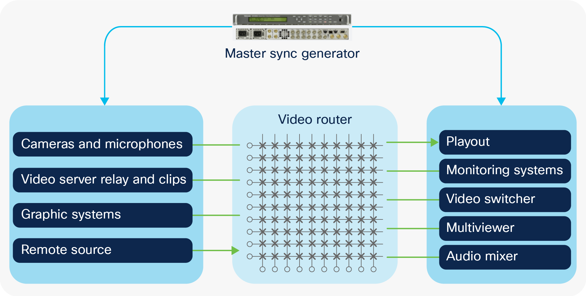
SDI facility leveraging black burst for time sync
With the move from SDI to IP, the need for endpoints to be synchronized is still required. With IP, Precession Time Protocol (PTP) is leveraged to distribute time.
For details on how PTP works on an Ethernet switch, refer to this white paper on IEEE 1588 PTP on the Cisco Nexus® 3100 Platform and 9000 Series Switches.
SMPTE 2059-2 and AES67 are most commonly used profiles in the media industry.
The AES67 PTP profile is based on the AES67 standard typically used by audio devices. It defines a default PTP domain 0 with sync interval -4 to 1 log second, announce interval 0 to 4 log second, announce timeout 2 to 10, and delay request minimum interval -4 to 5 log second.
SMPTE 2059-2 profile is specified by the 2110 standard and is used with devices configured to operate using 2110 for video and audio. It defines a default PTP domain 127 sync interval -8 to -1 log second, announce interval -3 to 1 log second, announce timeout 2 to 10, and delay request minimum interval -4 to 5 log second.
In most facilities equipment is configured to either operate in 2110 mode or use AES67. AES-R16-2016 proposes the PTP settings for interoperability between the existing profiles, as shown in Table 1.
Table 1. Common PTP intervals for Interoperability between IEE1588v2, AES67 and SMPTE 2059-2 profile
| Parameter |
Value |
| Domain |
127 |
| Sync Interval |
-3 (8 per second) |
| Announce Interval |
0 (1 per second) |
| Announce Timeout |
3 |
| Delay Request Minimum Interval |
-3 (8 per second) |
The main PTP clock types include:
● Grandmaster clock (GM). A grandmaster clock is the highest-ranking clock within its PTP domain and is the primary reference source for all other PTP elements.
● Secondary clock. A secondary clock receives the time information from a primary clock by synchronizing itself with the primary clock. It does not redistribute the time to another clock. In the data center, servers are typically PTP secondary clocks.
● Ordinary clock. An ordinary clock is a PTP clock with a single PTP port. It can be a primary clock (grandmaster) or a secondary clock.
● Boundary Clock (BC). A boundary clock is the intermediary device between a PTP grandmaster and its PTP secondary clients. It has multiple PTP ports in a domain and maintains the time scale used in the domain. Different ports on the boundary clock can be primary ports or secondary ports. The boundary clock terminates the PTP flow, recovers the clock and timestamp, and regenerates the PTP flow. A secondary port recovers the clock and primary ports to regenerate the PTP packets.
Transparent Clock (TC). A transparent clock measures the time needed for a PTP event message to transit the device and then compensates for the packet delay.
To be able to scale, the PTP boundary clock is the preferred implementation of PTP in an IP fabric. This distributes the overall load across all the network switches instead of putting all the load on the GM, which can only support a limited number of secondary.
PTP operates in one of three different modes: multicast, mixed, and unicast mode. In multicast mode, all messages between the grandmaster and secondary use multicast. In mixed mode, sync, follow-up, and announce use multicast and the secondary sends delay-request as a unicast message and primary responds with unicast delay-response. In unicast mode, all messages are unicast.
A Cisco® Nexus 9000 Series Switch supports multicast mode, mixed and unicast mode without negotiation. When operating in mixed or unicast mode, the source IP used on the PTP boundary clock must be an interface IP, like a loopback interface. The secondary sending the unicast message must use this IP as the destination IP.
Also, PTP primary can operate in one-step mode or two-step mode. In one-step mode, the time stamp is a part of the sync message, so the primary only sends sync and delay-response and secondary gets the timestamp from sync and use delay-request for offset calculation. In two-step mode the primary sends a sync followed by a follow-up where the timestamp is added. The nexus 9300 and 9200 switches operate as a two-step primary. The Nexus 9500-R can operate as both a one-step and two-step primary, however, we recommend running the Nexus 9500-R as a one-step primary.
Network deployments in a broadcast facility
There are mainly three deployment architectures seen in a broadcast facility, namely, using a single switch where endpoints are connected to the switch (Figure 2), a spine-and-leaf network with all broadcast equipment connected to the leaf (Figure 3), and a hybrid spine-and-leaf network where broadcast equipment is connected to both the spine and leaf (Figure 4).

Single switch
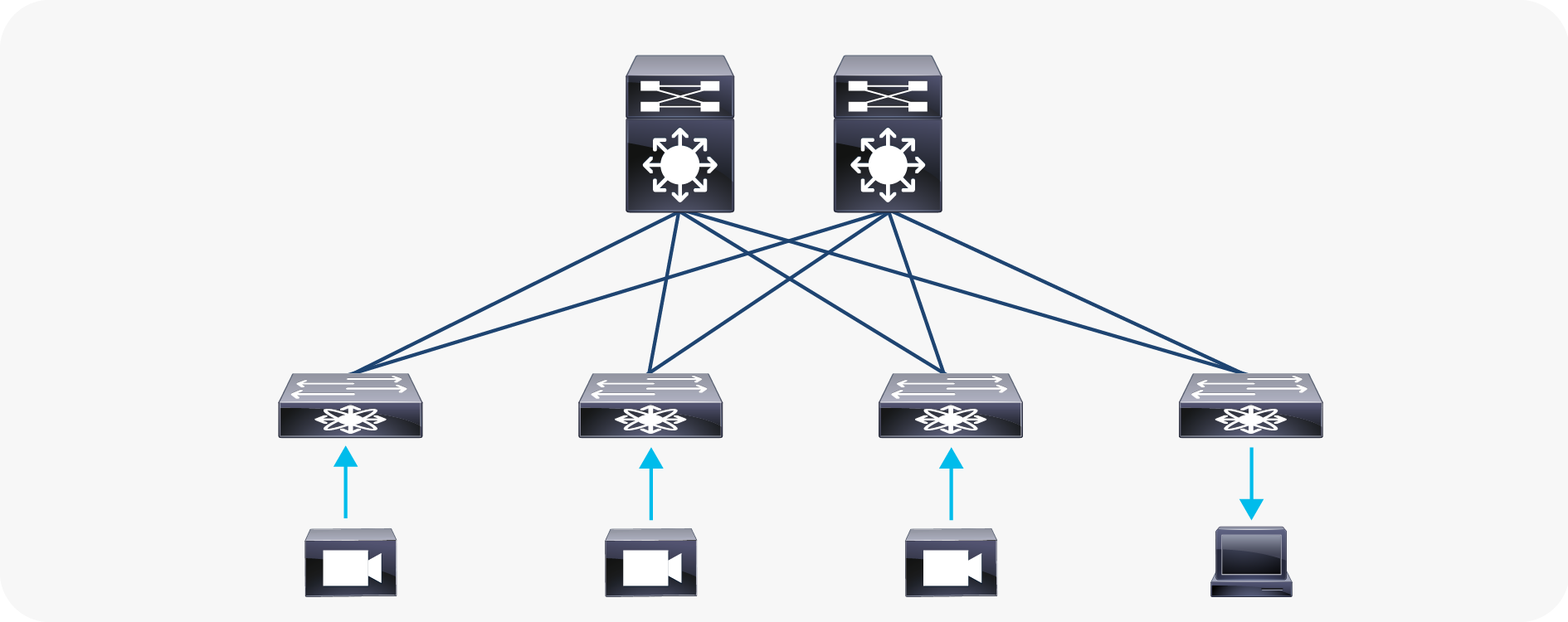
Spine and leaf
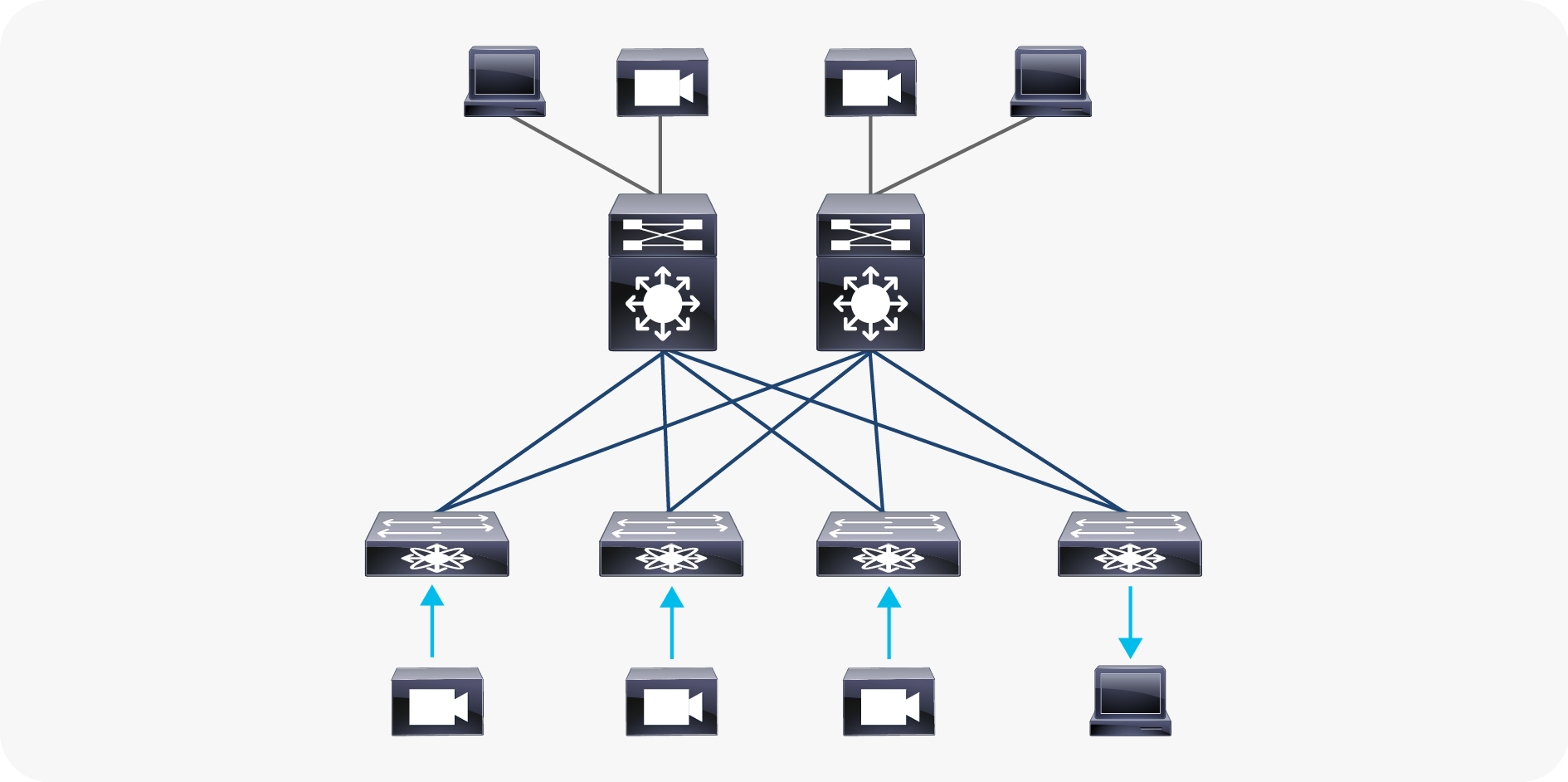
Hybrid spine and leaf
To add redundancy, the endpoints are typically dual-connected to redundant networks (as defined by SMPTE 2022-7), as shown below in figure 5.
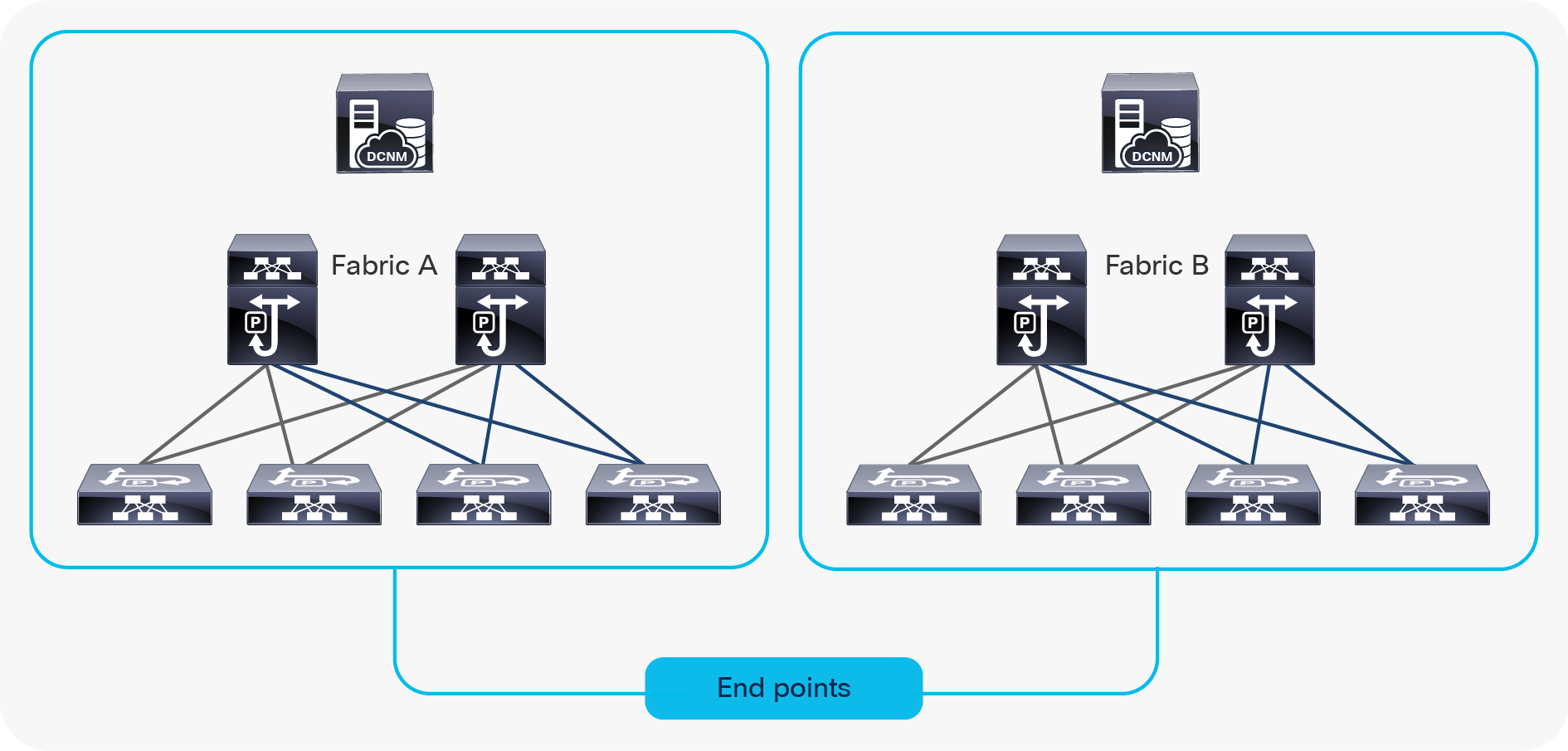
Redundant network
In any type of network deployment architecture, it is recommended to use a pair of PTP grandmaster (GM) clocks for redundancy. Both GM clocks must use the same time source so that they are locked to the same reference. Typically, GPS is utilized as a time source.
In deployments that do not utilize network redundancy, the GM clocks can be directly connected to the network switch. With redundant network deployments, an external PTP feeder switch or a pair of feeder switches can be used as a boundary clock (preferred design). In a scenario where, external feeder switch is not utilized, the two redundant fabrics can be interconnected to distribute PTP. These topologies are described in Figures 6 and 7a through d.
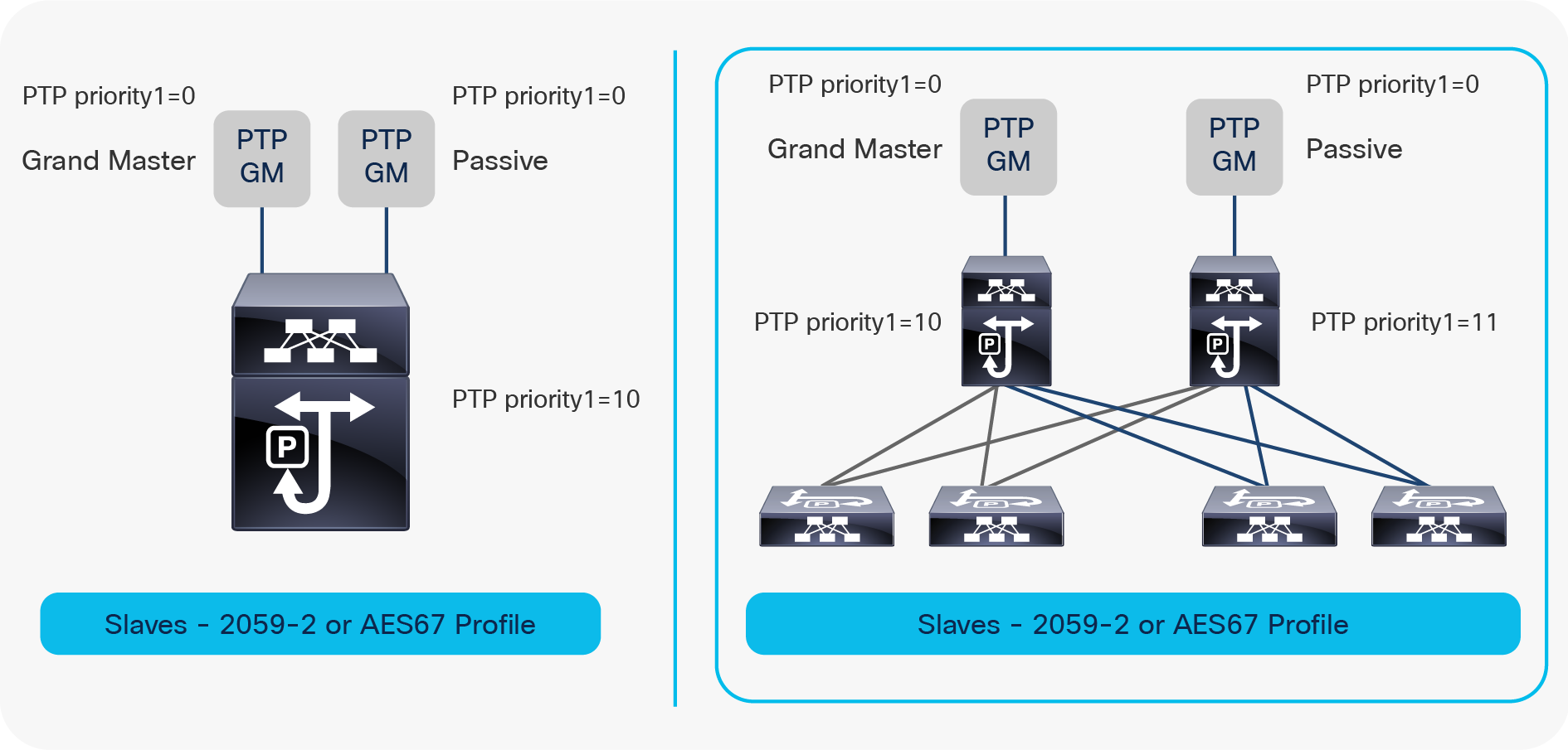
PTP deployment example in non-redundant networks
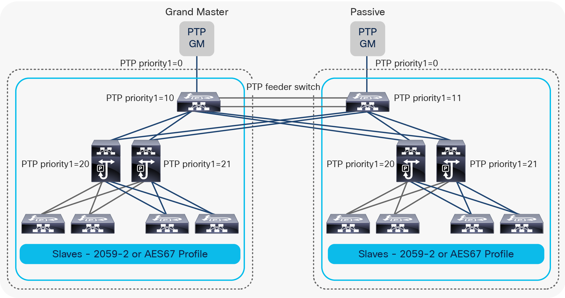
PTP deployment example in redundant network utilizing redundant PTP feeder switch
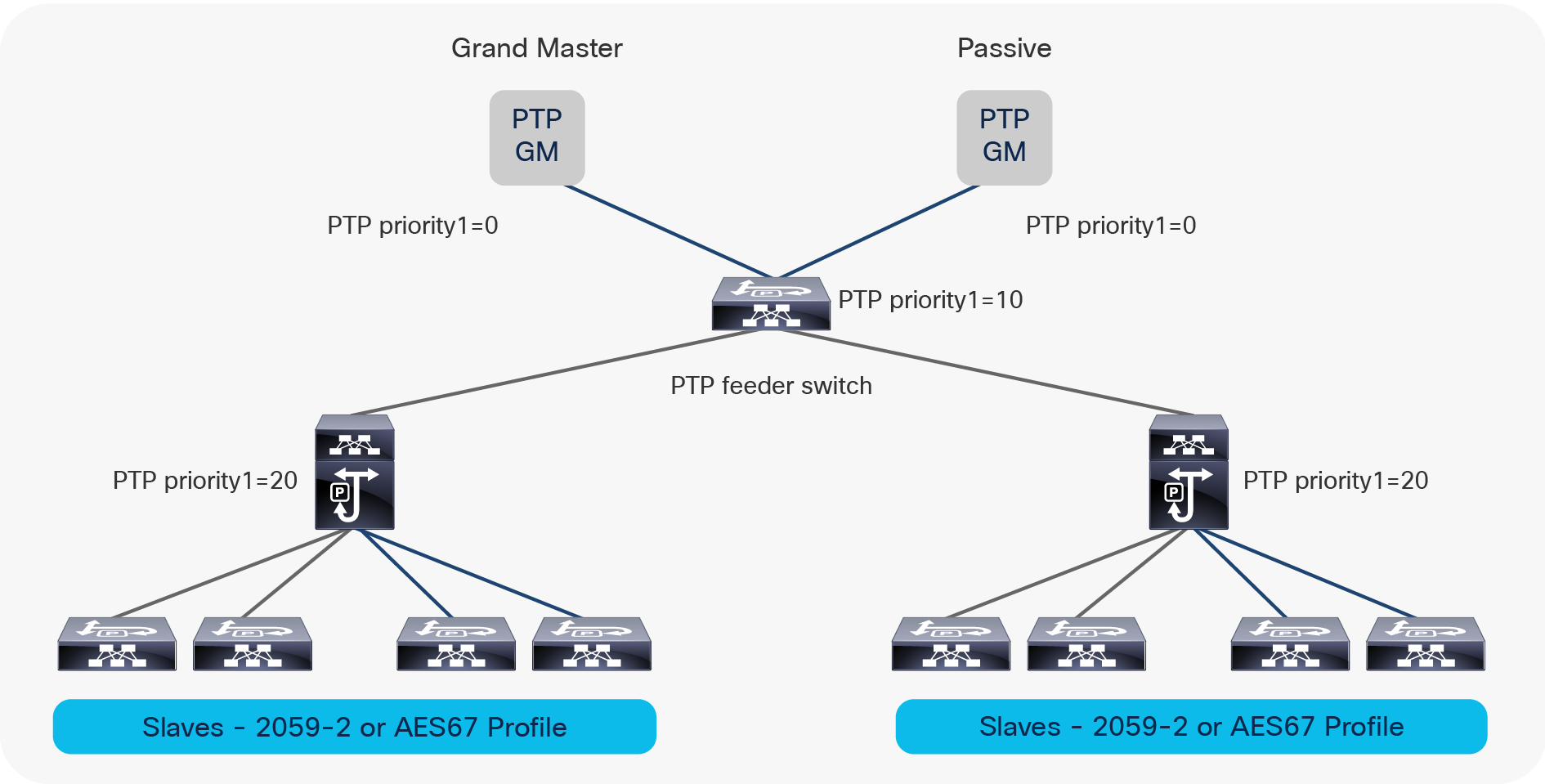
PTP deployment example in redundant network utilizing a single PTP feeder switch
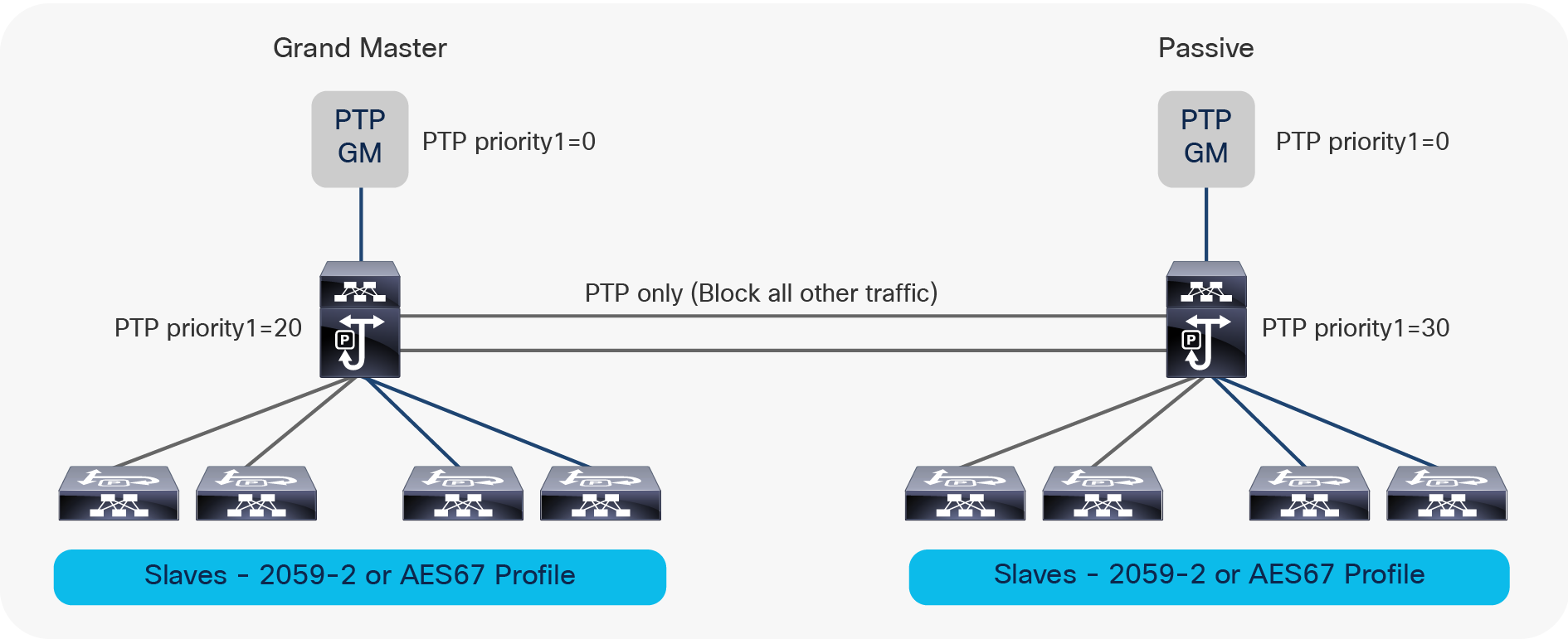
PTP deployment example in redundant network without a PTP feeder switch
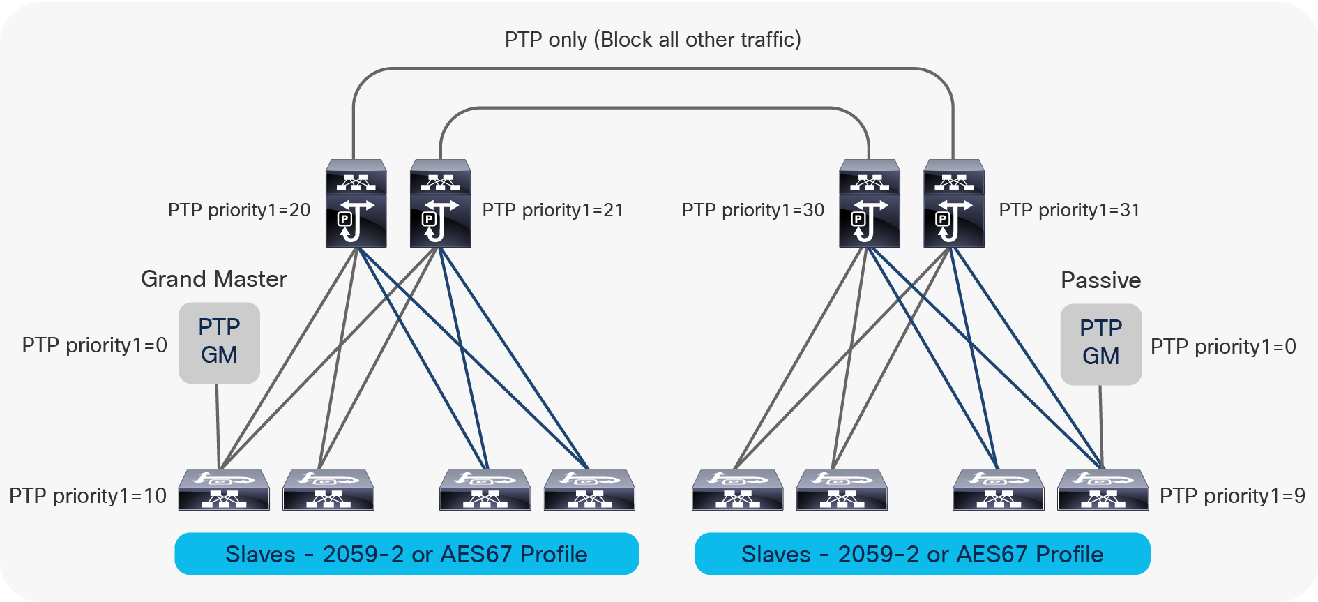
PTP deployment example in redundant network without a PTP feeder switch
It is important to set the PTP priority1 value such that the GM election is deterministic. The GM should be configured with a value of 0, the backup GM with a value of 0 as well.
The next boundary clock layer is configured with a value 10 and so on. This ensures that on a GM failure, Best Master Clock Algorithm (BMCA) election picks the backup GM and on both GMs’ failure, the PTP feeder switch acts as the primary and so on.
It is recommended to configure the links between the GM and the PTP feeder switch and the links between the PTP feeder switch and the fabric switches as layer 3 point-to-point interfaces. The same applies to the direct link between the two fabrics where the links must be configured as point-to-point layer 3 interfaces Also, it is important to ensure that no video or audio traffic traverses the two fabrics via the feeder switches or the direct link. This can be accomplished by not enabling Protocol Independent Multicast (PIM) or unicast routing protocol on the feeder switch or the direct link between the two fabrics. An Access Control List (ACL) can also be used to permit only PTP and block all other traffic on those links.
PTP configuration on the Cisco Nexus 9000 (Cisco NX-OS)
Cisco Nexus 9000 switches support IEEE1588v2, SMPTE2059-2, and AES67 media profiles. Each port can be individually configured with either of the supported profiles.
This allows devices that require either the IEEE1588v2 profile or SMPTE 2059-2/AES67 profile to co-exist on same fabric. It is recommended to use PTP intervals, as described in Table 1. Figure 8 shows an example of a network with 2059-2 and AES67 secondary.
Cisco NX-OS configuration example
feature ptp
ptp domain 127
ptp source 192.168.100.2
clock protocol ptp vdc 1
interface Ethernet1/49
! Interface with SMPTE 2059-2 profile
ptp
ptp delay-request minimum interval smpte-2059-2 -3
ptp announce interval smpte-2059-2 0
ptp sync interval smpte-2059-2 -3
ptp announce timeout smpte-2059-2 3
interface Ethernet1/2
! Interface with SMPTE AES67 profile
ptp
ptp delay-request minimum interval aes67 -3
ptp announce interval aes67 0
ptp sync interval aes67 -2 -3
ptp announce timeout aes67 3
ptp multicast master-only
On the Nexus 9500-R, you need to additionally enable PTP one-step mode and PTP offload. PTP offload enables scale as the PTP process runs on the line card CPU.
ptp offload
ptp clock-mode one-step
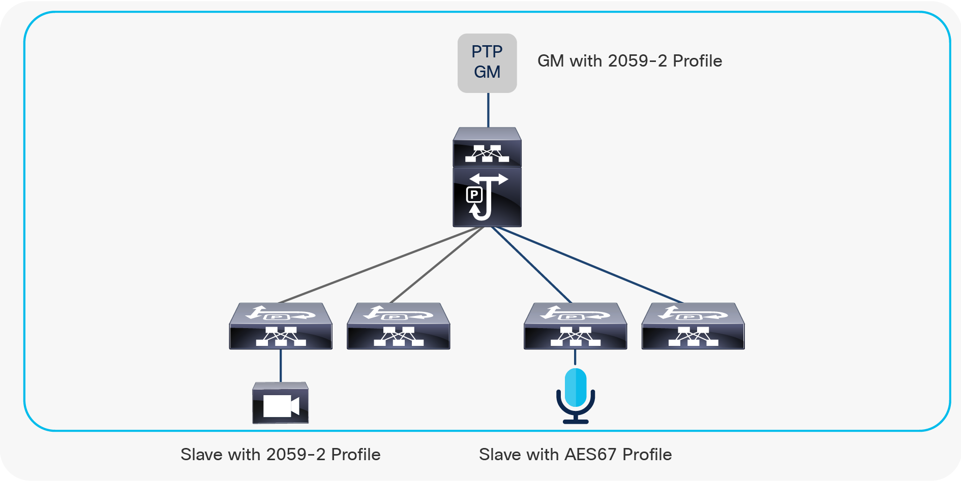
Network with 2059-2 and AES67 secondary
PTP and control plane policing
On the Cisco Nexus 9000 switch, traffic to the control plane is policed to protect it from any misbehaving neighbor. In the default control plane profile, PTP is limited to 280 kbps.
As media profiles have more aggressive intervals compared to the default profile, Control plane policing (COPP) must be adjusted to ensure PTP packets are policed to a slightly higher value. It is recommended to increase it from 280 kbps to 1024 kbps. Steps to increase the policer are shown below:
! Create a copy of the default CoPP profile
N9k# copp copy profile strict prefix pmn
! Modify the class that includes PTP and increase the CIR to 1024 kbps
N9K(config)# policy-map type control-plane pmn-copp-policy-strict
N9K(config-pmap)# class pmn-copp-class-redirect
N9K(config-pmap-c)# police cir 1500 kbps bc 128000 bytes conform transmit violate drop
! Apply the new policy
N9K(config)# control-plane
N9K(config-cp)# service-policy input pmn-copp-policy-strict
This operation can cause disruption of control traffic. Proceed (y/n)? [no] yes
On the 9500-R no changes are necessary for CoPP. The default CoPP policy can be used
PTP with a non-PTP-aware network switch
Occasionally the network transporting PTP may include a non-PTP-aware switch in the path between the GM and the secondary. When this happens, the switch treats PTP like any other data traffic, which could impact PTP accuracy. The network can still be used for PTP delivery by ensuring proper Quality-of-Service (QoS) configuration is in place to prioritize PTP traffic over all other traffic. On the Nexus switch operating in the boundary clock, PTP is automatically prioritized and queued in the control queue (highest priority), hence no additional QoS changes are needed.
Also, it is a good practice to configure secondary to operate in mixed mode instead of multicast mode. With mixed mode, the delay request being unicast is not sent to all other secondary in that segment. If the secondary is configured in multicast mode, the delay request/response messages will unnecessarily be sent to all other secondary in the segment.
Additionally, you may need to add static Internet Group Management Protocol (IGMP) snooping or an IGMP entry to forward PTP traffic (multicast/mixed mode).
Verifying PTP on Nexus 9000 switches (Cisco NX-OS)
Following are some show commands that you can use to verify PTP operation on a Nexus 9000 switch:
N9k# show ptp brief
PTP port status
-----------------------------------
Port State
--------------------- ------------
Eth1/49 Slave – Interface to master
Eth1/50 Master – Interface towards a slave
Eth1/51 Passive – Backup interface towards master
Eth1/52 Master – Interface towards a slave
N9K# show ptp corrections
PTP past corrections
Slave Port SUP Time Correction(ns) MeanPath Delay(ns)
Eth1/49 Mon Mar 4 17:33:31 2019 721865 -32 264
Eth1/49 Mon Mar 4 17:33:31 2019 600765 -92 264
Eth1/49 Mon Mar 4 17:33:31 2019 469997 4 264
Eth1/49 Mon Mar 4 17:33:31 2019 343886 64 260
Eth1/49 Mon Mar 4 17:33:31 2019 223425 -104 252
Eth1/49 Mon Mar 4 17:33:31 2019 91948 80 248
The correction should be under 500ns
N9k# show ptp parent
PTP PARENT PROPERTIES
Parent Clock:
Parent Clock Identity: 00:ea:bd:ff:fe:85:c7:15
Parent Port Number: 132
Observed Parent Offset (log variance): N/A
Observed Parent Clock Phase Change Rate: N/A
Parent IP: 192.168.100.2
Grandmaster Clock:
Grandmaster Clock Identity: 08:00:11:ff:fe:22:8a:7f
Grandmaster Clock Quality:
Class: 248
Accuracy: 49
Offset (log variance): 15652
Priority1: 0
Priority2: 128
N9k#show ptp clock
PTP Device Type : boundary-clock
PTP Device Encapsulation : layer-3
PTP Source IP Address : 192.168.100.12
Clock Identity : 00:3a:9c:ff:fe:54:a0:c7
Clock Domain: 127
Slave Clock Operation : Two-step
Master Clock Operation : Two-step
Slave-Only Clock Mode : Disabled
Number of PTP ports: 4
Priority1 : 255
Priority2 : 255
Clock Quality:
Class : 248
Accuracy : 254
Offset (log variance) : 65535
Offset From Master : 48
Mean Path Delay : 256
Steps removed : 3
Correction range : 1000000
MPD range : 1000000000
Local clock time : Mon Mar 4 17:36:38 2019
Nexus switches that support PTP media profiles
Following is a list of Cisco switches that support the PTP media profiles:
● Cisco Nexus 9200 Series Switches
● Nexus 9300-EX Switch
● Nexus 9300-FX Switch
● Nexus 9300-FX2 Switch
● Nexus 9300-FX3
● Nexus 9300-GX
● Nexus 9300-GX2A and 2B
● Nexus 9364C
● Nexus 9508-R with N9K-X9636C-R, N9K-X9636Q-R, N9K-X9636C-RX
● Nexus 9504-R with N9K-X9636C-R, N9K-X9636Q-R, N9K-X9636C-RX
● Nexus 9508-R2 with N9K-X9724D-R2
PTP and multi-site deployments
In a multi-site deployment, sometimes there is a requirement to extend PTP across sites. If these sites are geographically in the same location, connected over a direct fiber, PTP can be extended (Figure 9). When fabrics are in different geographical locations connected over Wide Area Networks (WAN), care must be taken when extending PTP. Varying latency across a WAN can compromise PTP accuracy as the PTP mean path delay is constantly changing. At times, it is recommended to use different PTP grandmasters in each site and not extend PTP across these sites (see Figure 10).
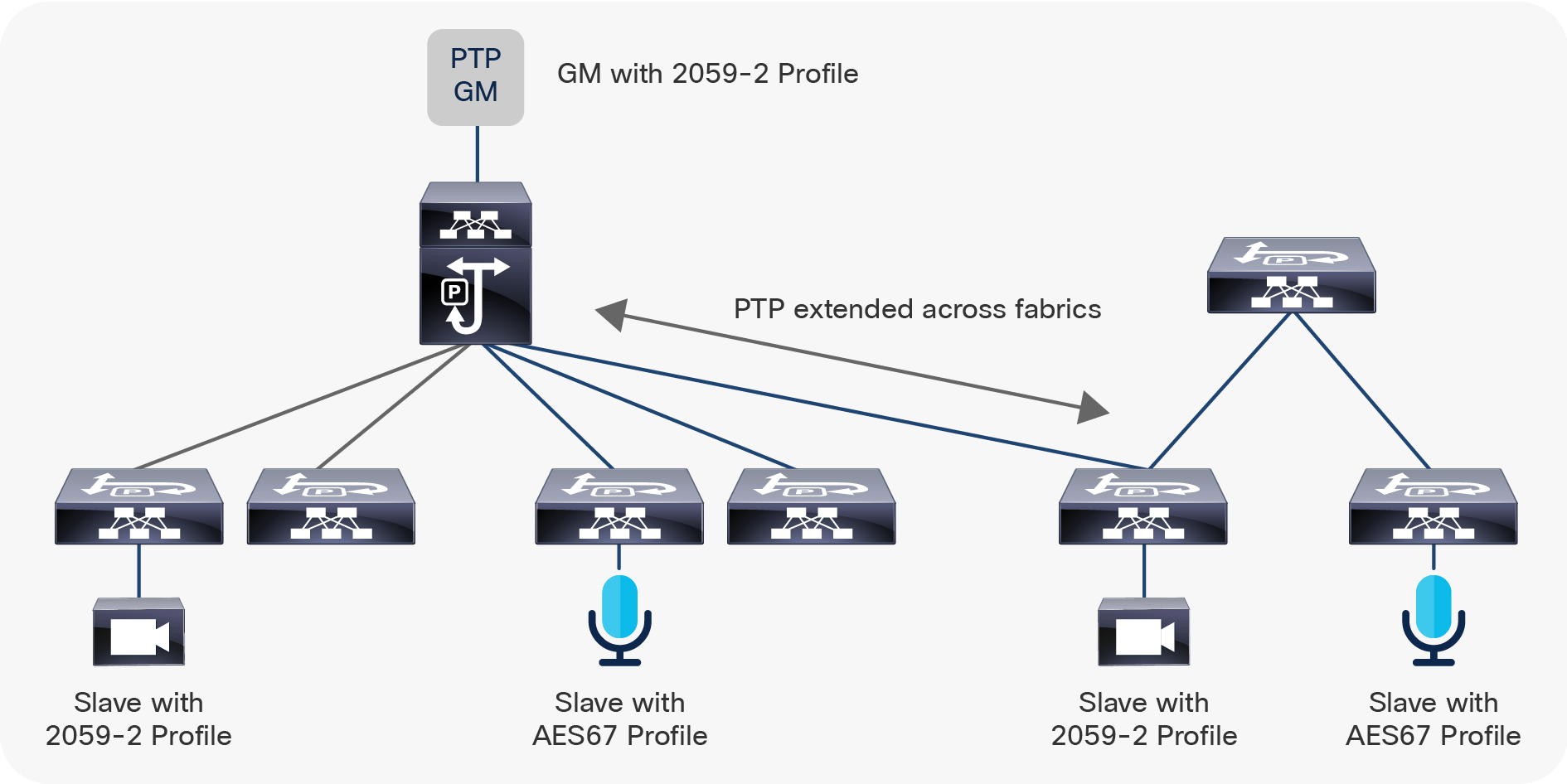
PTP and multi-site deployment
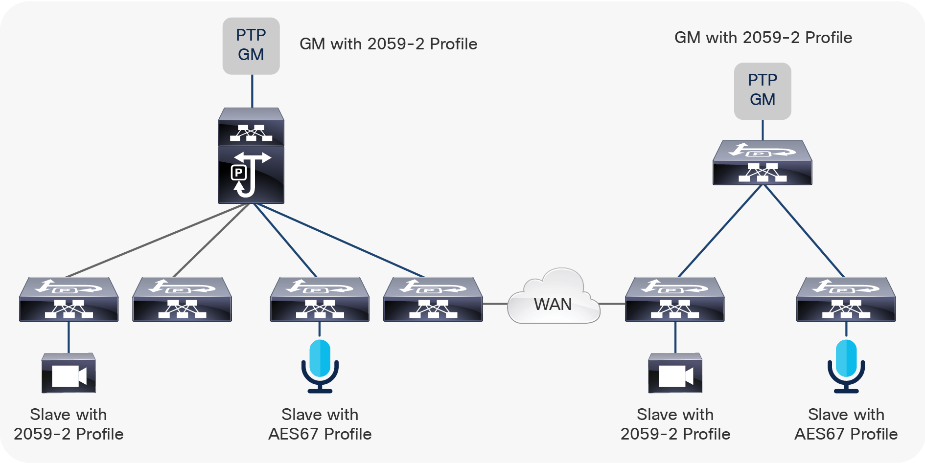
Sites using GMs connected locally without a PTP extension
Following are some of recommended best practices when using PTP:
● Configure the switch to work in boundary-clock mode when supported
● Ensure the number of secondary connected to a switch does not exceed the verified scalability. See the configuration guides on Verified Scale
● Configure the secondary to operate in secondary-only mode (use “ptp multicast master-only” at the CLI)
● Ensure COPP is adjusted to allow PTP to go up to 1024 kbps on 9200 and 9300
● Ensure certified optics and transceivers are used and the mean path delay is low, and most importantly, not varying too much
Troubleshooting PTP on Cisco NX-OS
There are a few basic checks one can do to verify PTP functionality.
(1) Correction and mean path delay
N9K# show ptp corrections
PTP past corrections
Slave Port SUP Time Correction(ns) MeanPath Delay(ns)
Eth1/49 Mon Mar 4 17:33:31 2019 721865 -32 264
Eth1/49 Mon Mar 4 17:33:31 2019 600765 -92 264
Eth1/49 Mon Mar 4 17:33:31 2019 469997 4 264
Eth1/49 Mon Mar 4 17:33:31 2019 343886 64 260
Eth1/49 Mon Mar 4 17:33:31 2019 223425 -104 252
Eth1/49 Mon Mar 4 17:33:31 2019 91948 80 248
The corrections should be under 500 ns, and the mean path delay should be around the same value and not changing constantly.
(2) Counters
N9K# show ptp counters all
PTP Packet Counters of Interface Eth1/1:
----------------------------------------------------------------
Packet Type TX RX
---------------- -------------------- --------------------
Announce 0 613201
Sync 0 4879973
FollowUp 0 4879973
Delay Request 4671478 0
Delay Response 0 4671478
PDelay Request 0 0
PDelay Response 0 0
PDelay Followup 0 0
Management 0 613604
Ensure the boundary clock sends PTP packets as per the configured intervals. In a boundary clock operating in 2-step mode, the sync and follow-up counter should match. The delay request and response counter typically match too. Occasionally, there could be a few packets lost, but they do not impact the overall accuracy. A relatively big difference in the follow-up or delay response counter could indicate loss of PTP packets.
(3) Monitoring COPP
The control plane policer drops will impact PTP performance. Ensure COPP is adjusted to allow PTP to exceed the default policer value. Even with a boundary clock that has multiple secondary, a CIR value of 1024 kbps is sufficient. If drops continue even after increasing COPP to 1024kbps, it is very likely there is a misbehaving endpoint or a misconfigured/misbehaving boundary clock and needs to be further investigated.
Leaf-1 # show policy-map interface control-plane class nbm-copp-class-redirect
Control Plane
Service-policy input: nbm-copp-policy-strict
class-map nbm-copp-class-redirect (match-any)
match access-group name nbm-copp-acl-ptp
match access-group name nbm-copp-acl-ptp-l2
match access-group name nbm-copp-acl-ptp-uc
set cos 1
police cir 1024 kbps , bc 32000 bytes
module 1 :
transmitted 1724750 bytes;
dropped 0 bytes;
(4) Switched Port Analyzer (SPAN) and PTP
Port mirroring is an effective tool to capture PTP packets. As PTP packets are sent and received by the CPU, a CPU span captures all PTP packets. The Cisco Nexus 9000 also supports Rx (ingress SPAN) that can be sent to an external collector. CPU-generated packets, such as PTP generated by the Nexus 9000, will not be seen on Tx SPAN. This is a platform limitation.
monitor session 1
source interface Ethernet1/1 both
destination interface sup-eth0
no shut
ethanalyzer local interface inband limit-captured-frames 0 write bootflash:ptp.pcap
The SPAN capture is saved on bootflash and can be exported for offline analysis.
An example topology involving a Cisco SPG8000A Tektronix grandmaster with a Nexus 9000 switch is shown in Figure 11.
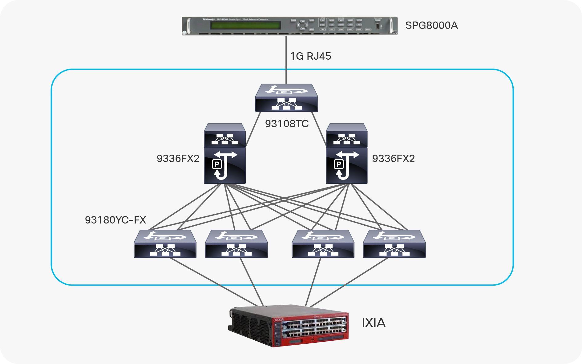
PTP deployment example
The topology involves a Cisco SPG8000A gateway running a SMPTE 2059-2 profile in 2-step multicast mode (Figure 12). All switches are configured to run a boundary clock. The links between the switches are point-to-point layer 3 links.
IXIA has one physical interface connected to each switch and simulates 128 secondary per switch.
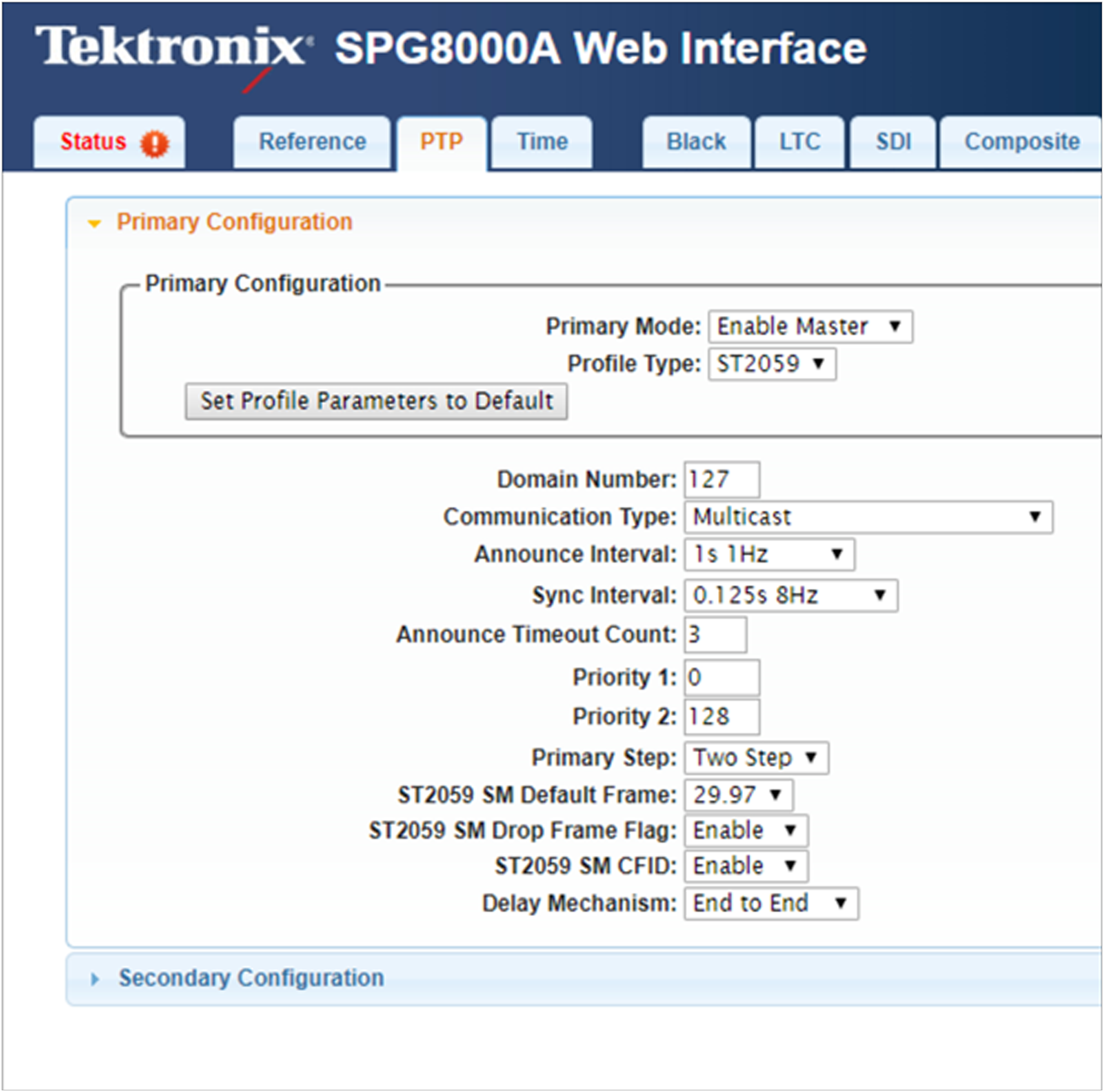
Tektronics setting
Following is the configuration on all PTP-enabled interfaces on the Nexus 9000 boundary clock switches:
feature ptp
ptp domain 127
ptp source 192.168.100.11
ptp correction-range 1000000
interface Ethernet1/49
ptp
ptp delay-request minimum interval smpte-2059-2 -3
ptp announce interval smpte-2059-2 0
ptp sync interval smpte-2059-2 -3
ptp announce timeout smpte-2059-2 3
On the Nexus 9000 switch facing the secondary, configure “ptp multicast master-only” to prevent secondary from taking over the primary role:
interface Ethernet1/1
ptp
ptp delay-request minimum interval smpte-2059-2 -3
ptp announce interval smpte-2059-2 0
ptp sync interval smpte-2059-2 -3
ptp announce timeout smpte-2059-2 3
ptp multicast master-only
Following is the PTP status on the Nexus 93108TC Switch connected to Tektronics:
93108TC # show ptp brief
PTP port status
-----------------------------------
Port State
--------------------- ------------
Eth1/48 Slave >>> To Tektronics GM
Eth1/49 Master >>> To Spine 1
Eth1/50 Master >>> To Spine 2
93108TC # show ptp parent
PTP PARENT PROPERTIES
Parent Clock:
Parent Clock Identity: 08:00:11:ff:fe:22:8a:7f
Parent Port Number: 3
Observed Parent Offset (log variance): N/A
Observed Parent Clock Phase Change Rate: N/A
Parent IP: 172.16.100.1
Grandmaster Clock:
Grandmaster Clock Identity: 08:00:11:ff:fe:22:8a:7f
Grandmaster Clock Quality:
Class: 248
Accuracy: 49
Offset (log variance): 15652
Priority1: 0
Priority2: 128
Following is the PTP status on spine 1:
Spine1# show ptp brief
PTP port status
-----------------------------------
Port State
--------------------- ------------
Eth1/1 Slave >>> To 93108TC
Eth1/33 Master >>> To Leaf switch
Eth1/34 Master >>> To Leaf switch
Eth1/35 Master >>> To Leaf switch
Eth1/36 Master >>> To Leaf switch
Spine1# show ptp parent
PTP PARENT PROPERTIES
Parent Clock:
Parent Clock Identity: e0:0e:da:ff:fe:a8:bf:31
Parent Port Number: 192
Observed Parent Offset (log variance): N/A
Observed Parent Clock Phase Change Rate: N/A
Parent IP: 172.16.100.2
Grandmaster Clock:
Grandmaster Clock Identity: 08:00:11:ff:fe:22:8a:7f
Grandmaster Clock Quality:
Class: 248
Accuracy: 49
Offset (log variance): 15652
Priority1: 0
Priority2: 128
Spine 1 sees Tektronics as the grandmaster.
Spine1# show ptp clock
PTP Device Type : boundary-clock
PTP Device Encapsulation : layer-3
PTP Source IP Address : 192.168.100.2
Clock Identity : 00:ea:bd:ff:fe:85:c7:15
Clock Domain: 127
Slave Clock Operation : Two-step
Master Clock Operation : Two-step
Slave-Only Clock Mode : Disabled
Number of PTP ports: 5
Priority1 : 255
Priority2 : 255
Clock Quality:
Class : 248
Accuracy : 254
Offset (log variance) : 65535
Offset From Master : 64
Mean Path Delay : 240
Steps removed : 2
Correction range : 1000000
MPD range : 1000000000
Local clock time : Mon Mar 11 16:00:06 2019
PTP status on the leaf:
Leaf1# show ptp brief
PTP port status
-----------------------------------
Port State
--------------------- ------------
Eth1/1 Master
Eth1/49 Slave >>> To Spine 1
Eth1/50 Master
Eth1/51 Passive >>> Redundant connection to Spine 1
Eth1/52 Master
Leaf1# show ptp parent
PTP PARENT PROPERTIES
Parent Clock:
Parent Clock Identity: 00:ea:bd:ff:fe:85:c7:15
Parent Port Number: 128
Observed Parent Offset (log variance): N/A
Observed Parent Clock Phase Change Rate: N/A
Parent IP: 192.168.100.2
Grandmaster Clock:
Grandmaster Clock Identity: 08:00:11:ff:fe:22:8a:7f
Grandmaster Clock Quality:
Class: 248
Accuracy: 49
Offset (log variance): 15652
Priority1: 0
Priority2: 128
Leaf1# show ptp clock
PTP Device Type : boundary-clock
PTP Device Encapsulation : layer-3
PTP Source IP Address : 192.168.100.11
Clock Identity : 00:3a:9c:ff:fe:55:be:c7
Clock Domain: 127
Slave Clock Operation : Two-step
Master Clock Operation : Two-step
Slave-Only Clock Mode : Disabled
Number of PTP ports: 5
Priority1 : 255
Priority2 : 255
Clock Quality:
Class : 248
Accuracy : 254
Offset (log variance) : 65535
Offset From Master : 84
Mean Path Delay : 272
Steps removed : 3
Correction range : 1000000
MPD range : 1000000000
Local clock time : Mon Mar 11 16:03:12 2019
Overall, in a period of 48 hours, the peak offset IXIA secondary observed were -158 and 164 ns.
Time synchronization is a requirement for proper functioning of a broadcast facility, and PTP has proven to be an effective mechanism to distribute time in an IP deployment. The Cisco Nexus 9000 Series Switches, with a boundary clock capability, can provide a robust implementation of PTP across the IP fabric.