New and Changed Information
The following table provides an overview of the changes to the organization and content of this guide up to the current release.
|
Release |
Feature or Change Description |
Where Documented |
|---|---|---|
|
9.3(5) |
First release of this document |
Hybrid PTP Platform Overview
Beginning with Cisco NX-OS Release 9.3(5), a hybrid SyncE-PTP topology is supported to achieve the end-to-end network precision frequency required for circuit emulation and cell tower frequency referring.
The following figure shows the topology with the external timing source as the grandmaster clock (T-GM). The T-GM provides the timing source for the Telecom Boundary Clocks (T-BCs).
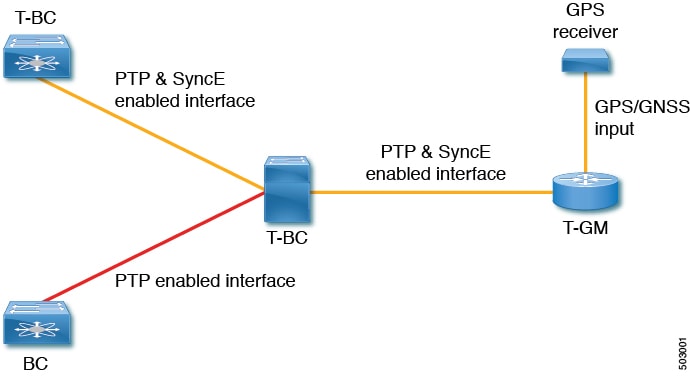
Telecom Grandmaster (T-GM): Provides timing for other network devices and does not synchronize its local clock to other network devices.
Telecom Boundary Clock (T-BC): Synchronizes its local clock to a T-GM or an upstream T-BC clock and provides timing information to downstream T-BC or T-TSC clocks.
Guidelines and Limitations
PTP Telecom Profile Guidelines and Limitations
PTP Telecom Profile has the following guidelines and limitations:
-
PTP Telecom Profile is supported only on the Cisco Nexus N9K-C93180YC-FX3S switch.
-
1 Pulse per Second (1PPS) output is enabled by default. UTC/SMB port is in output mode and hence 1PPS output is enabled.
-
Only PTP class B is supported
-
Only Telecom Boundary Clock (T-BC) is supported
-
Cisco's Telecom Profile G.8273.2 feature is compliant with the ITU-T G.8273.2 : Timing characteristics of telecom boundary clocks and telecom time slave clocks standard with the exception that 1PPS output is not aligned with PTP.
-
TOD output is not supported
 Note |
Time of Day and PTP GM are not supported in Cisco NX-OS Release 9.3(5). |
Frequency Synchronization Guidelines and Limitations
Frequency Synchronization has the following guidelines and limitations:
-
SyncE is supported only on the Cisco Nexus N9K-C93180YC-FX3S switch.
-
SyncE is supported only on physical interfaces.
-
A maximum four ethernet interfaces can be monitored for SyncE selection input at any given instance of time.
-
Each quad port group on the PHY provides one reference clock.
-
Only one Ethernet interface from each quad port group can be configured as a SyncE input (one reference clock for each port group). There is no restriction on SyncE outputs.
-
SyncE must be enabled explicitly on the member interfaces for a port-channel. If a member interface of a port-channel is locked as a SyncE source, the ability to send out DNU on other member interfaces enabled for SyncE is controlled via the global command fsync transmit dnu lag-members .
-
Only G.8275.1 hybrid profile in BC mode is supported.
-
For a list of qualified optics for this release, see the Cisco Optics Compatibility Matrix.
Note |
GPS and GNSS are not supported in Cisco NX-OS Release 9.3(5). |
Configuring PTP Globally
This procedure describes the steps involved to configure PTP telecom profile including the clock and its settings to be consistent with ITU-T Telecom Profiles for Frequency.
Before you begin
The QoS TCAM region Ingress SUP [ingress-sup] must be set to 768 or higher. Follow these steps:
-
Check the TCAM region by using the show hardware access-list tcam region command.
-
If the Ingress SUP region is not set to 768 or higher, then configure the Ingress SUP TCAM region using the command hardware access-list tcam region ing-sup 768 . Copy the running configuration to the startup configuration (copy running-config startup-config ) and reload the switch.
SUMMARY STEPS
- configure terminal
- feature ptp
- ptp profile { 8275-1 | default }
- Profile Default: mode { hybrid | non-hybrid | none }
- exit
- ptp source ip-address
- Profile Default: ptp priority1 value
- Profile Default: ptp priority2 value
- ptp pdelay-req-interval value
- Profile Default: ptp domain value
DETAILED STEPS
| Command or Action | Purpose | |||
|---|---|---|---|---|
| Step 1 |
configure terminal Example: |
Enters global configuration mode. |
||
| Step 2 |
feature ptp Example: |
Enables the global PTP feature. |
||
| Step 3 |
ptp profile { 8275-1 | default } Example: |
Enables a PTP profile and enters the PTP profile configuration mode. For more information about the commands supported through the profile types in this command, see
|
||
| Step 4 |
Profile Default: mode { hybrid | non-hybrid | none } Example: |
Configures the PTP operational mode for the switch: hybrid : The SyncE source acts as the PTP source. default : The local/1588 clock acts as the PTP source.
|
||
| Step 5 |
exit Example: |
Exits the PTP profile configuration mode and returns to the global configuration mode. |
||
| Step 6 |
ptp source ip-address Example: |
Configures the source IPv4 address for all the PTP packets in the multicast PTP mode. |
||
| Step 7 |
Profile Default: ptp priority1 value Example: |
Configures the priority1 value to use when advertising this clock. This value overrides the default criteria (clock quality, clock class, etc.) for best master clock selection. Lower values take precedence.
|
||
| Step 8 |
Profile Default: ptp priority2 value Example: |
Configures the priority2 value to use when advertising this clock. This value overrides the default criteria (clock quality, clock class, etc.) for best master clock selection. Lower values take precedence.
|
||
| Step 9 |
ptp pdelay-req-interval value Example: |
Configures the peer delay request interval. value : Range is from 0 through 5. |
||
| Step 10 |
Profile Default: ptp domain value Example: |
Specifies the PTP clock domain value.
|
Configuring PTP on an Interface
This procedure describes the steps that are involved to configure PTP telecom profile for interfaces.
Note |
Some commands that are described in this procedure are automatically enabled and configured when the ptp profile 8275-1 global command is set. See Configuring PTP Globally for more information. |
Before you begin
This procedure along with configuring frequency synchronization on the interface, constitutes the required interface settings for the "hybrid PTP" platform. For more information regarding the interface frequency synchronization configuration, see .
SUMMARY STEPS
- configure terminal
- interface ethernet slot / port
- [ no ] ptp
- Profile Default: ptp transport ethernet
- Profile Default: ptp transmission multicast
- Profile Default: ptp role dynamic
- (Optional) ptp destination-mac non-forwardable rx-no-match accept
- Profile Default: ptp cost value
- Profile Default: ptp delay-request minimum interval log-seconds
- Profile Default: ptp announce interval log-seconds
- Profile Default: ptp sync interval log-seconds
- (Optional) [no] ptp announce timeout count
- (Optional) [ no ] ptp profile-override
DETAILED STEPS
| Command or Action | Purpose | |||
|---|---|---|---|---|
| Step 1 |
configure terminal Example: |
Enters global configuration mode. |
||
| Step 2 |
interface ethernet slot / port Example: |
Specifies the interface on which you are configuring PTP telecom profile parameters and enters the interface configuration mode. |
||
| Step 3 |
[ no ] ptp Example: |
Enables PTP on the interface. |
||
| Step 4 |
Profile Default: ptp transport ethernet Example: |
Specifies the transport mechanism that is used to send PTP packets. For etnernet , PTP packets are carried only in Eth frame (Eth/ptp).
|
||
| Step 5 |
Profile Default: ptp transmission multicast Example: |
Configures the PTP transmission method that is used by the interface. For multicast , PTP uses multicast destination IP address 224.0.1.129 as per IEEE 1588 standards for communication between devices.
|
||
| Step 6 |
Profile Default: ptp role dynamic Example: |
Configures the PTP role of the interface. For dynamic , the best master clock algorithm (BMCA) assigns the role.
|
||
| Step 7 |
(Optional) ptp destination-mac non-forwardable rx-no-match accept Example: |
(Optional)
Accepts and responds to non-forwardable destination MAC address packets. These destination MAC addresses are used in the PTP messages that are exchanged between the GM clock, PTP-master clock, and PTP-slave clocks. |
||
| Step 8 |
Profile Default: ptp cost value Example: |
Configures the value to be used in the BMCA's selection of the best master clock. If all the parameters mentioned in the standard are the same, then this local priority is used.
|
||
| Step 9 |
Profile Default: ptp delay-request minimum interval log-seconds Example: |
Configures the minimum interval that is allowed between PTP delay messages when the port is in the master state.
|
||
| Step 10 |
Profile Default: ptp announce interval log-seconds Example: |
Configures the interval between PTP announce messages on an interface or the number of PTP intervals before a timeout occurs on an interface.
|
||
| Step 11 |
Profile Default: ptp sync interval log-seconds Example: |
Configures the interval between PTP synchronization messages on an interface.
|
||
| Step 12 |
(Optional) [no] ptp announce timeout count Example: |
(Optional)
Configures the number of PTP intervals before a timeout occurs on an interface. The range for the interval timeout is from 2 to 4 intervals. |
||
| Step 13 |
(Optional) [ no ] ptp profile-override Example: |
(Optional)
Disabled by default, when enabled, allows you to change the following commands in this interface configuration:
|
PTP Profile Defaults
The following table lists the ranges and default values for the commands that are automatically configured when the global command ptp profile is set. You cannot change the range for the affected global commands beyond those allowed by the configured profile. However, in the interface mode, they can be changed if the ptp profile-override command is set.
Note |
For Cisco NX-OS Release 9.3(5), only the Cisco Nexus N9K-C93180YC-FX3S supports either option in this command. |
|
Parameter |
Scope or Configuration Mode |
Default Profile's Supported Range of Values |
Default Profile's Default Value |
8275.1 Profile's Supported Range of Values |
8275.1 Profile's Default Value |
With 'ptp profile-override' Configured on an Interface Supported Range of Values (Default is Based on Configured Profile) |
|---|---|---|---|---|---|---|
|
mode |
global |
none |
none |
hybrid |
hybrid |
no change |
|
domain |
global |
0 to 63 |
0 |
24 to 43 |
24 |
no change |
|
priority1 |
global |
0 to 255 |
255 |
128 |
128 |
no change |
|
priority2 |
global |
0 to 255 |
255 |
0 to 255 |
128 |
no change |
|
cost |
interface |
Not configurable |
Not configurable |
0 to 255 |
128 |
0 to 255 |
|
transport |
interface |
ipv4 |
ipv4 |
ethernet |
ethernet |
ethernet, ipv4 |
|
transmission |
interface |
multicast, unicast |
multicast |
multicast |
multicast |
no change |
|
role |
interface |
dynamic, master, slave |
dynamic |
dynamic |
dynamic |
no change |
|
announce interval |
interface |
0 to 4 0 to 4 with aes67 -3 to 1 with smpte-2059-2 |
1 |
-3 |
-3 |
-3 to 4 0 to 4 with aes67 -3 to 1 with smpte-2059-2 |
|
delay-request minimum interval |
interface |
-1 to 6 -4 to 5 with aes67 -4 to 5 with smpte-2059-2 |
0 |
-4 |
-4 |
-4 to 6 -4 to 5 with aes67 -4 to 5 with smpte-2059-2 |
|
sync interval |
interface |
-3 to 1 -4 to 1 with aes67 -7 to 0 with smpte-2059-2 |
-2 |
-4 |
-4 |
-4 to 1 -4 to 1 with aes67 -7 to 0 with smpte-2059-2 |
Licensing Requirements for Synchronous Ethernet (SyncE)
|
Product |
License Requirement |
|---|---|
|
Cisco NX-OS |
Install the SyncE add-on license. For a complete explanation of the Cisco NX-OS licensing scheme, see the Cisco NX-OS Licensing Guide. |
Enabling Frequency Synchronization
Use this procedure to enable frequency synchronization, set the quality level of the switch, identify the clock ID for ESMC extended TLV, and configure the ESMC peer timeout for software upgrades.
SUMMARY STEPS
- configure terminal
- [ no ] feature frequency-synchronization
- [ no ] fsync quality itu-t option{ 1 | 2 generation { 1 | 2 }
- fsync clock-identity mac-address | no fsync clock-identity
- [ no ] fsync esmc peer receive timeout{ 0 | value}
- [ no ] fsync transmit dnu lag-members
- (Optional) copy running-config startup-config
DETAILED STEPS
| Command or Action | Purpose | |||
|---|---|---|---|---|
| Step 1 |
configure terminal Example: |
Enters global configuration mode. |
||
| Step 2 |
[ no ] feature frequency-synchronization Example: |
Enables frequency synchronization on the switch. |
||
| Step 3 |
[ no ] fsync quality itu-t option{ 1 | 2 generation { 1 | 2 } Example: |
Specifies the quality level for the switch. The default is option 1 .
|
||
| Step 4 |
fsync clock-identity mac-address | no fsync clock-identity Example: |
Specifies the clock ID to be used for Ethernet Synchronization Message Channel (ESMC) extended TLV. If no clock ID is configured, the system uses the default VDC MAC address. |
||
| Step 5 |
[ no ] fsync esmc peer receive timeout{ 0 | value} Example: |
Specifies the ESMC peer receive timeout during ISSU. 0 disables the ESMC peer receive timeout. value is the ESMC receive timeout in seconds. Enter a value from 120 through 600. Default = 120. This command ensures that the ESMC control plane, and thus, selection, is not removed during software upgrade for a period of the value . |
||
| Step 6 |
[ no ] fsync transmit dnu lag-members Example: |
SyncE must be enabled explicitly on the member interfaces for a port-channel. If a member interface of a port-channel is locked as a SyncE source, the ability to send out DNU (Do Not Use) QLs on other member interfaces that are enabled for SyncE is controlled by this command. If enabled and an interface that is driving the clock for the switch is part of a port-channel, then any members of the port-channel will also send out DNU QL if SyncE is enabled on that interface. If disabled, the system drives the QL of the selected source on all interfaces regardless of whether they are in the same port-channel as the interface driving the clock. |
||
| Step 7 |
(Optional) copy running-config startup-config Example: |
(Optional)
Copies the running configuration to the startup configuration. |
Configuring Frequency Synchronization on an Interface
Use this procedure to configure frequency synchronization on a specific interface.
Before you begin
This procedure along with configuring PTP telecom profile on the same interface, constitutes the required interface settings for the "hybrid PTP" platform. For more information about the interface PTP telecom profile configuration, see Configuring PTP on an Interface.
Make sure that you have globally enabled frequency synchronization on the device (global configuration command feature frequency-synchronization ).
SUMMARY STEPS
- configure terminal
- [ no ] interface ethernet slot / port
- [ no ] frequency synchronization
- [no] selection input
- [no] ssm disable
- [ no ] quality { receive | transmit } { exact | highest | lowest } itu-t option ql-option ql
- [no] priority value
- [no] wait-to-restore minutes
DETAILED STEPS
| Command or Action | Purpose | |||
|---|---|---|---|---|
| Step 1 |
configure terminal Example: |
Enters global configuration mode. |
||
| Step 2 |
[ no ] interface ethernet slot / port Example: |
Specifies the interface on which you are enabling frequency synchronization and enters the interface configuration mode. |
||
| Step 3 |
[ no ] frequency synchronization Example: |
Enables frequency synchronization on the interface and enters the interface frequency synchronization configuration mode. The system selects the frequency signal to be used for clocking transmission, but does not enable the use of the interface as an input.
|
||
| Step 4 |
[no] selection input Example: |
Specifies the interface as a timing source to be passed to the selection algorithm. |
||
| Step 5 |
[no] ssm disable Example: |
Disables sending ESMC packets and ignores any received ESMC packets. |
||
| Step 6 |
[ no ] quality { receive | transmit } { exact | highest | lowest } itu-t option ql-option ql Example: |
Adjusts the Quality Level (QL) value that is used in received or transmitted SSMs, before it is used in the selection algorithm. Each timing source has a QL associated with it which provides the accuracy of the clock. This QL information is transmitted across the network via SSMs over the Ethernet Synchronization Messaging Channel (ESMC) so that devices can know the best available source to use for synchronization.
|
||
| Step 7 |
[no] priority value Example: |
Configures the priority of the frequency source on the interface. This priority is used in the clock-selection algorithm to choose between two sources that have the same QL. Values range from 1 (highest priority) to 254 (lowest priority). The default value is 100.
|
||
| Step 8 |
[no] wait-to-restore minutes Example: |
Configures the wait-to-restore time, in minutes, for frequency synchronization on the interface. minutes is the amount of time after the interface initializes before it is used for synchronization. Values range from 0 to 12. The default value is 5.
|
Verifying the Configuration
This section contains example outputs from show commands used to verify the Frequency Synchronization and PTP Telecom Profile configuratrions.
Verifying the Frequency Synchronization Configuration
After performing the frequency synchronization configuration tasks, use this reference to check for configuration errors and verify the configuration.
show frequency synchronization configuration errors
The output of this command displays errors in the frequency synchronization configuration.
The following example shows the mismatch between the global quality itu-t option and the interface quality receive itu-t option :
switch# show frequency synchronization configuration errors

Elysian2(config)# show frequency synchronization configuration errors
Ethernet1/9
    quality receive exact itu-t option 1 PRC
* The QL that is configured is from a different QL option set than is
configured globally.


!Command: show running-config fsync_mgr all
!Running configuration last done at: Mon Feb 10 06:06:15 2020
!Time: Mon Feb 10 06:09:18 2020

version 9.3(5) Bios:version 00.04
feature frequency-synchronization

fsync quality itu-t option 2 generation 1 << must be the same as interface
fsync clock-identity 0
fsync esmc peer receive timeout 120

interface Ethernet1/9
  frequency synchronization
    selection input
    ssm disable
    quality receive exact itu-t option 1 PRC << must be the same as global
    priority 100
    wait-to-restore 0

interface Ethernet1/13
  frequency synchronization
    selection input
    ssm disable
    quality receive exact itu-t option 1 PRC
    priority 110
    wait-to-restore 0
show running-config fsync_mgr all
The output of this command displays the current frequency synchronization configuration on the device.
The following is an example of the output of the show running-config fsync_mgr all command:
switch# show running-config fsync_mgr all

feature frequency-synchronization

fsync quality itu-t option 1
fsync clock-identity 0
fsync esmc peer receive timeout 120

interface Ethernet1/9
  frequency synchronization
    selection input
    ssm disable
    quality receive exact itu-t option 1 PRC
   priority 100
    wait-to-restore 0

interface Ethernet1/13
  frequency synchronization
    selection input
    priority 100
    wait-to-restore 0
show frequency synchronization interface brief
The output of this command displays all interfaces that have frequency synchronization configured. Sources that have been nominated as inputs have ‘S’ in the Flags (Fl) column. Sources that have not been nominated as inputs do not have ‘S’ displayed.
The following is an example of the output of the show frequency synchronization interface brief command:
switch# show frequency synchronization interface brief

Flags:  > - Up                D - Down              S - Assigned for selection
        d - SSM Disabled      x - Peer timed out    i - Init state
        e - SSM Enabled       s - Output squelched
Fl    Interface          QLrcv QLuse Pri QLsnd Output driven by
===== ================== ===== ===== === ===== ========================
>S    Eth1/9             PRC   PRC   100 PRC   Eth1/13
>Sds  Eth1/13            n/a   PRC   100 n/a   Eth1/13
show frequency synchronization interface ethernet
The output of this command displays individual (user-selected) interfaces with associated frequency synchronization information.
The following is an example of the output of the show frequency synchronization interface ethernet slot / port command:
switch# show frequency synchronization interface ethernet 1/9

Inteface State:UP
Assigned as input for Selection
  Wait-to-restore time 0 minute(s)
  SSM Enabled
    Peer Up for 00:07:01, last SSM received 0.307s ago
    Peer has come up 4 times and timed out 1 times
    ESMC SSMs        Total  Information     Event    DNU/DUS
      Sent:           1097         1088         9         83
      Received:        823          816         7        155
  Input:
    Up
    Last received QL: PRC
    Effective QL: PRC, Priority: 100
    Originator clock ID: fffffffffebfa543
    SyncE steps: 1, eSyncE steps: 1
    Not all steps run eSyncE; Chain of extended ESMC data is broken
    Supports frequency
  Output:
    Selected source: Eth1/13
    Selected source QL: PRC
    Effective QL: PRC
    Originator clock ID: fffffffffebfa863
    SyncE steps: 1, eSyncE steps: 1
    Not all steps run eSyncE; Chain of extended ESMC data is broken
  Next selection points:
show frequency synchronization selection (with PTP Profile 8275-1)
The output of this command displays the detailed view of the different selection points within the system.
Note |
This example shows the output when PTP profile 8275-1 is configured. |
The following is an example of the output of the show frequency synchronization selection slot / port command:
switch# show frequency synchronization selection
==============
Selection point: System Clock (T0) Selector (3 inputs, 1 selected)
  Last programmed 18.898s ago, and selection made 8.621s ago
  Next selection points
    Node scoped   :
  Uses frequency selection
  Used for local line interface output
  S  Input                     Last Selection Point         QL  Pri  Status
  == ========================  ========================  =====  ===  ===========
  11 Ethernet1/9               n/a                         PRC   99  Locked
     Ethernet1/13              n/a                         PRC  100  Available
     Internal0[1]              n/a                         SEC  255  Available
==============
Selection point: IEEE 1588 Clock Selector (3 inputs, 1 selected)
  Last programmed 18.898s ago, and selection made 18.626s ago
  Next selection points
    Node scoped   :
  Uses frequency selection
  S  Input                     Last Selection Point         QL  Pri  Status
  == ========================  ========================  =====  ===  ===========
     Ethernet1/9               n/a                         PRC   99  Unmonitored
     Ethernet1/13              n/a                         PRC  100  Unmonitored
  21 Internal0[1]              n/a                         SEC  255  Freerun    <<
show frequency synchronization selection (without PTP Profile 8275-1)
The output of this command displays the detailed view of the different selection points within the system.
Note |
This example shows the output when PTP profile 8275-1 is not configured. |
The following is an example of the output of the show frequency synchronization selection slot / port command:
switch# show frequency synchronization selection==============
Selection point: System Clock (T0) Selector (3 inputs, 1 selected)
  Last programmed 00:03:04 ago, and selection made 00:02:54 ago
  Next selection points
    Node scoped   :
  Uses frequency selection
  Used for local line interface output
  S  Input                     Last Selection Point         QL  Pri  Status
  == ========================  ========================  =====  ===  ===========
  11 Ethernet1/9               n/a                         PRC   99  Locked
     Ethernet1/13              n/a                         PRC  100  Available
     Internal0[1]              n/a                         SEC  255  Available
==============
Selection point: IEEE 1588 Clock Selector (3 inputs, 1 selected)
  Last programmed 00:03:04 ago, and selection made 3.296s ago
  Next selection points
    Node scoped   :
  Uses frequency selection
  S  Input                     Last Selection Point         QL  Pri  Status
  == ========================  ========================  =====  ===  ===========
     Ethernet1/9               n/a                         PRC   99  Unmonitored
     Ethernet1/13              n/a                         PRC  100  Unmonitored
  21 Internal0[1]              n/a                         SEC  255  Holdover   <<
show esmc counters all
The output of this command displays counters for sent and received ESMC SSMs.
The following is an example of the output of the show esmc counters all command:
ESMC Packet Counters of Interface Ethernet1/1:
    ESMC SSMs        Total  Information     Event    DNU/DUS
      Sent:              0            0         0          0
      Received:          0            0         0          0

ESMC Packet Counters of Interface Ethernet1/5:
    ESMC SSMs        Total  Information     Event    DNU/DUS
      Sent:              0            0         0          0
      Received:          0            0         0          0

ESMC Packet Counters of Interface Ethernet1/9:
    ESMC SSMs        Total  Information     Event    DNU/DUS
      Sent:           7685         7683         2          0
      Received:       7688         7682         6         19

----------------------------------------------------------------
show esmc counters interface ethernet
The output of this command displays counters for sent and received ESMC SSMs on a specific interface.
The following is an example of the output of the show esmc counters interface ethernet slot / port command:
ESMC Packet Counters of Interface Ethernet1/9:
    ESMC SSMs        Total  Information     Event    DNU/DUS
      Sent:           7955         7953         2          0
      Received:       7958         7952         6         19

----------------------------------------------------------------
Verifying the PTP Telecom Profile Configuration
After performing the PTP telecom profile configuration tasks, use this reference to verify the configuration.
show running-config ptp all
The output of this command displays global and interface configurations for PTP telecom profile.
The following is an example of the output of the show running-config ptp all command:
switch# show running-config ptp all
!Command: show running-config ptp all
!Running configuration last done at: Fri Feb 21 20:09:55 2020
!Time: Fri Feb 21 21:10:19 2020

version 9.3(5) Bios:version 01.00
feature ptp

ptp profile 8275-1
  mode hybrid
ptp source 0.0.0.0
ptp device-type boundary-clock
ptp priority1 128
ptp priority2 10
ptp pdelay-req-interval 0
no ptp notification type parent-change
no ptp notification type gm-change
no ptp notification type high-correction
no ptp notification type port-state-change
ptp correction-range 100000
no ptp correction-range logging
ptp management
ptp mean-path-delay 1000000000
ptp domain 24
ttag-marker-interval 60


interface Ethernet1/1
  ptp
  no ptp profile-override
  ptp destination-mac non-forwardable rx-no-match accept
  ptp transport ethernet
  ptp transmission multicast
  ptp role dynamic
  ptp cost 128
  ptp delay-request minimum interval -4
  ptp announce interval -3
  ptp sync interval -4
  ptp announce timeout 3

interface Ethernet1/6
  ptp
  no ptp profile-override
  ptp destination-mac non-forwardable rx-no-match accept
  ptp transport ethernet
  ptp transmission multicast
  ptp role dynamic
  ptp cost 128
  ptp delay-request minimum interval -4
  ptp announce interval -3
  ptp sync interval -4
  ptp announce timeout 3

interface Ethernet1/7
  ptp
  no ptp profile-override
  ptp destination-mac non-forwardable rx-no-match accept
  ptp transport ethernet
  ptp transmission multicast
  ptp role dynamic
  ptp cost 128
  ptp delay-request minimum interval -4
  ptp announce interval -3
  ptp sync interval -4
  ptp announce timeout 3

interface Ethernet1/8
  ptp
  no ptp profile-override
  ptp destination-mac non-forwardable rx-no-match accept
  ptp transport ethernet
  ptp transmission multicast
  ptp role dynamic
  ptp cost 128
  ptp delay-request minimum interval -4
  ptp announce interval -3
  ptp sync interval -4
  ptp announce timeout 3
Note |
The output of the show running-config ptp all command displays a complete list of all the PTP configured interfaces. |
show ptp parent
The output of this command displays the properties of a PTP parent.
The following is an example of the output of the show ptp parent command:
switch# show ptp parent
PTP PARENT PROPERTIES

Parent Clock:
Parent Clock Identity: 10:b3:d6:ff:fe:bf:a8:63
Parent Port Number: 0
Observed Parent Offset (log variance): N/A
Observed Parent Clock Phase Change Rate: N/A

Grandmaster Clock:
Grandmaster Clock Identity: 10:b3:d6:ff:fe:bf:a8:63
Grandmaster Clock Quality:
        Class: 248
        Accuracy: 254
        Offset (log variance): 65535
        Priority1: 128
        Priority2: 10
show ptp corrections
The output of this command displays up to the last 2000 correction details for each PTP slave port.
The following is an example of the output of the show ptp corrections command:
switch# show ptp corrections
PTP past corrections
-----------------------------------------------------------------------------------
Slave Port            SUP Time                 Correction(ns)    MeanPath Delay(ns)
----------  -------------------------------  ------------------  ------------------
Eth1/3      Thu Feb 20 22:51:02 2020 861523           4           260
Eth1/3      Thu Feb 20 22:51:02 2020 735961           4           260
Eth1/3      Thu Feb 20 22:51:02 2020 610170           4           268
Eth1/3      Thu Feb 20 22:51:02 2020 483106           0           280
Eth1/3      Thu Feb 20 22:51:02 2020 355745           0           280
Eth1/3      Thu Feb 20 22:51:02 2020 229924          -4           268
Eth1/3      Thu Feb 20 22:51:02 2020 104819          -4           268
Eth1/3      Thu Feb 20 22:51:01 2020 979604           8           272
show ptp clock
The output of this command displays the properties of the local clock, including clock identity.
The following is an example of the output of the show ptp clock command:
switch# show ptp clock
PTP Device Type : boundary-clock
PTP Device Encapsulation : NA
PTP Source IP Address : 0.0.0.0
Clock Identity : 10:b3:d6:ff:fe:bf:a8:63
Clock Domain: 24
Slave Clock Operation : Unknown
Master Clock Operation : Two-step
Slave-Only Clock Mode : Disabled
Number of PTP ports: 35
Priority1 : 128
Priority2 : 10
Clock Quality:
        Class : 248
        Accuracy : 254
        Offset (log variance) : 65535
Offset From Master : 0
Mean Path Delay : 0
Steps removed : 0
Correction range : 100000
MPD range : 1000000000
Local clock time : Wed Feb 26 17:08:34 2020
Hardware frequency correction : NA
PTP Clock state               : Free-Run
show ptp brief
The output of this command displays the PTP clock state for each configred port.
The following is an example of the output of the show ptp brief command:
switch# show ptp brief
PTP port status
-----------------------------------
Port                  State
--------------------- ------------
Eth1/1                Slave
Eth1/6                Disabled
Eth1/7                Disabled
Eth1/8                Disabled
Eth1/10               Master
Eth1/11               Disabled
Eth1/12               Disabled
Eth1/13               Master
Eth1/14               Disabled
Eth1/15               Disabled
Eth1/16               Disabled
Eth1/17               Disabled
Eth1/18               Disabled
Eth1/19               Disabled
Eth1/20               Disabled
Eth1/21               Disabled
Eth1/22               Disabled
Eth1/23               Disabled
Eth1/24               Disabled
Eth1/25               Disabled
Eth1/26               Disabled
Eth1/27               Disabled
Eth1/28               Disabled
Eth1/29               Disabled
Eth1/30               Disabled
Eth1/31               Disabled
Eth1/32               Disabled
Eth1/33               Disabled
Eth1/34               Disabled
Eth1/35               Disabled
Eth1/36               Disabled
Eth1/37               Disabled
Eth1/38               Disabled
Eth1/39               Disabled
Eth1/40               Disabled
show ptp clock foreign-masters record
The output of this command displays the state of foreign masters known to the PTP process. For each foreign master, the output displays the clock identity, basic clock properties, and whether the clock is being used as a grandmaster..
The following is an example of the output of the show ptp clock foreign-master-record command:
switch# show ptp port status
P1=Priority1, P2=Priority2, C=Class, A=Accuracy,
OSLV=Offset-Scaled-Log-Variance, SR=Steps-Removed
GM=Is grandmaster

---------   -----------------------  ---  ----  ----  ---  -----  --------
Interface         Clock-ID           P1   P2    C     A    OSLV   SR
---------   -----------------------  ---  ----  ----  ---  -----  --------

Eth1/1    00:00:00:00:00:00:00:01    128  128   6     33   65535  0    GM
 Feedback