Integrating Layer 4 to Layer 7 Services to Cisco Nexus Hyperfabric
Available Languages
Bias-Free Language
The documentation set for this product strives to use bias-free language. For the purposes of this documentation set, bias-free is defined as language that does not imply discrimination based on age, disability, gender, racial identity, ethnic identity, sexual orientation, socioeconomic status, and intersectionality. Exceptions may be present in the documentation due to language that is hardcoded in the user interfaces of the product software, language used based on RFP documentation, or language that is used by a referenced third-party product. Learn more about how Cisco is using Inclusive Language.
- US/Canada 800-553-2447
- Worldwide Support Phone Numbers
- All Tools
 Feedback
 Feedback
Layer 4 to Layer 7 Services in Cisco Nexus Hyperfabric
Layer 3 Firewall Design with a Firewall as the Gateway
Layer 3 Firewall Design with Fabric as the Gateway
BGP import and export policies
Introduction – This document describes design options for Layer 4 to Layer 7 services connected to a Cisco Nexus Hyperfabric. For general information on Cisco Nexus Hyperfabric, go to: https://www.cisco.com/c/en/us/support/data-center-networking/nexus-hyperfabric/series.html
Layer 4 to Layer 7 Services in Cisco Nexus Hyperfabric
The figures below illustrate examples of Cisco Nexus Hyperfabric topology with Layer 4 to Layer 7 services such as firewalls and load balancers. Although there is no static switch role such as spine and leaf switches in Cisco Nexus Hyperfabric, this document mainly uses spine-leaf topologies.
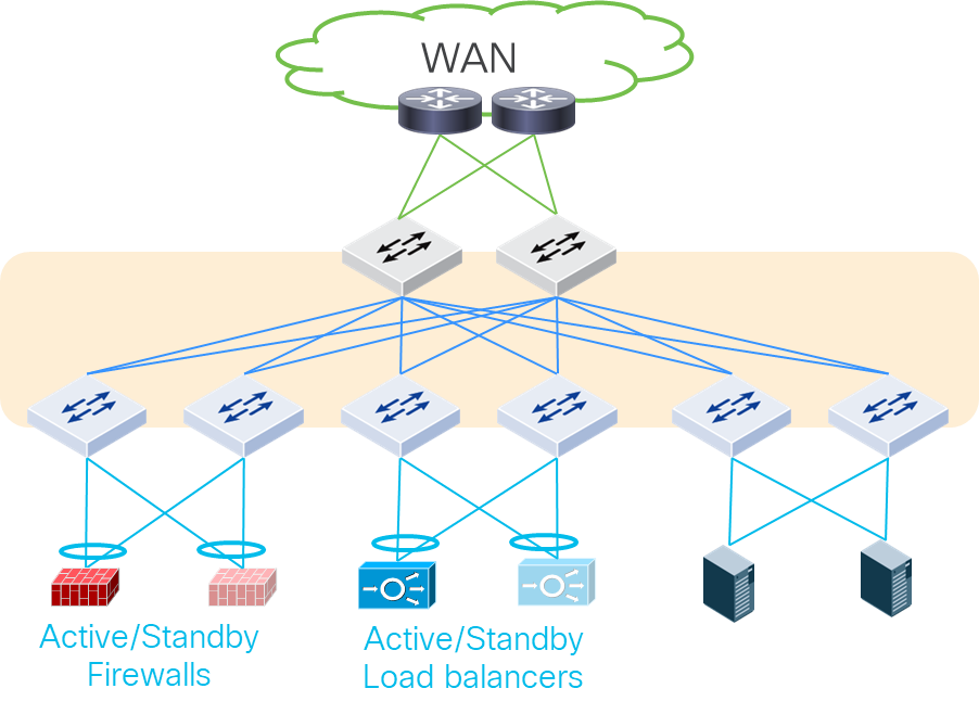
Layer 4 to Layer 7 services in Cisco Nexus Hyperfabric
Cisco Nexus Hyperfabric is a VXLAN EVPN fabric within which you can create Layer 2 and Layer 3 connections to the outside world, including hosts and service devices on any switches. Thus, Layer 4 to Layer 7 services can be connected to any switches in the fabric, although the figure above connects Layer 4 to Layer 7 services only under leaf switches. The figure below shows another example in which perimeter north-south firewalls are connected to spine switches and east-west firewalls are connected to leaf switches.
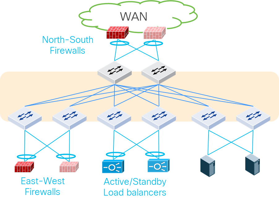
Perimeter Layer 4 to Layer 7 services connected to Cisco Nexus Hyperfabric
Although this document mainly uses a spine-leaf topology with physical firewalls connected to leaf switches, the same design considerations is applicable to other types of topologies and other types of Layer 4 to Layer 7 services such as load balancers and Intrusion Prevention Systems (IPS) regardless of whether they are physical or virtual appliances.
Each Layer 4 to Layer 7 device should be connected to more than one switch for redundancy. For Layer 4 to Layer 7 service appliances and servers that run Layer 4 to Layer 7 service VMs, the use of Layer 2 connectivity with trunking multiple VLANs is a common deployment option.
For Layer 2 connectivity, the common redundancy options are the following:
· Individual links: individual physical links connected to different switches
o Typically called active-standby/active-active bonding/teaming.
o This is the common default behavior on server side.
· Multi-chassis port channel: a logical link to aggregate multiple physical links connected to different switches.
o This is a common option to connect network devices that use SVIs (Switch Virtual Interfaces) and servers.
o Cisco Nexus Hyperfabric supports up to two switches for each port channel using LACP active mode.
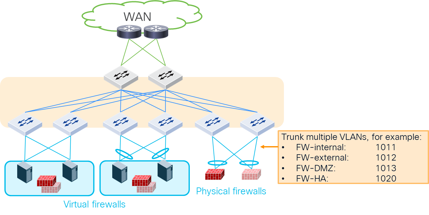
Physical connectivity examples
For details about port channel configurations, see:
The figure below illustrates typical design options for firewall insertion. Cisco Nexus Hyperfabric does not yet support the Policy Based Routing (PBR) capability to insert network service devices for specific traffic, often referred to as service insertion. This implies that it is required to deploy traditional design options (example 1-3 in the figure below) to ensure the required service devices are inserted based on routing or bridging.
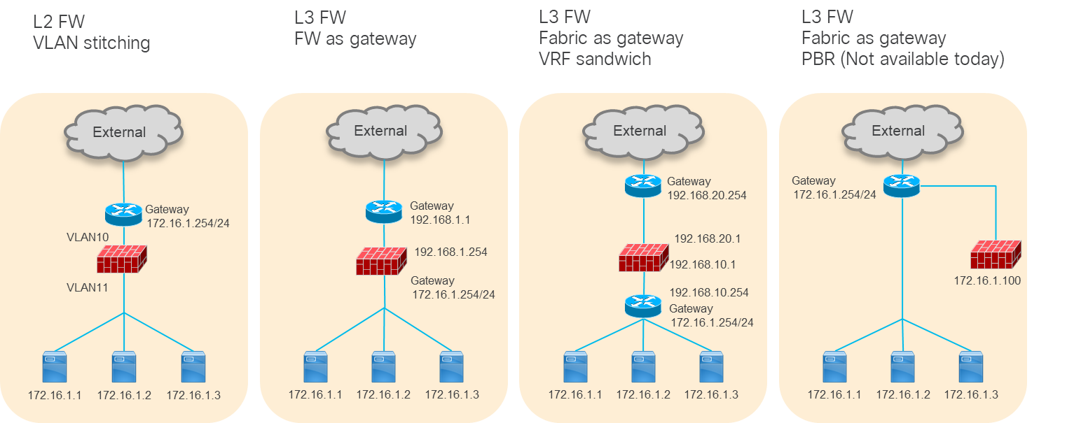
Typical firewall design options (PBR is not yet available on Hyperfabric)
Because the use of a Layer 3 service device is more common, this document will cover the second and third examples: Layer 3 firewall as the gateway and VRF sandwich by using Cisco Nexus Hyperfabric as the gateway.
Layer 3 Firewall Design with a Firewall as the Gateway
The figure below illustrates a logical network design example to insert Layer 3 firewalls between logical networks: VLAN10 and VLAN20. Because the active-standby firewall pair is the gateway, the logical networks don’t have anycast gateway IP addresses, which are also known as SVIs (Switch Virtual Interfaces).
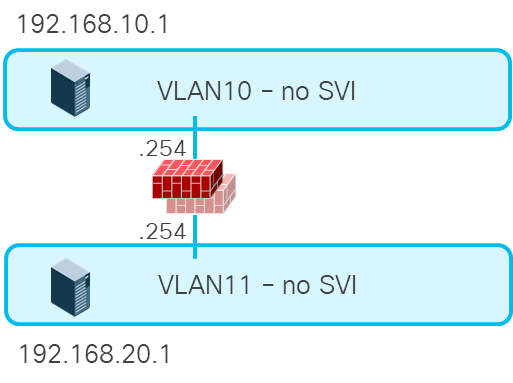
Layer 3 firewall between Layer 2 only logical networks
If the firewall needs to be inserted for all inter-subnet traffic, this design is the right approach. However, this design doesn’t take advantage of anycast gateway capability in the fabric and requires a firewall interface for each logical network. Thus, the use of a fabric as the gateway could be a better approach for other use cases, such as high-performance intra-fabric traffic for compute host to storage communications.
Layer 3 Firewall Design with Fabric as the Gateway
The figure below illustrates a logical network design example to insert perimeter north-south firewalls in Cisco Nexus Hyperfabric. When a server in a VRF instance (Vrf-HF1 in this example) talks to the external network, the firewall is inserted based on routing. One of the firewall logical interfaces (FW-inside in this example) is connected through the logical network with an SVI (VLAN101 in this example). Static route or dynamic routing in Vrf-HF1 needs to be configured accordingly to send traffic to FW-inside.
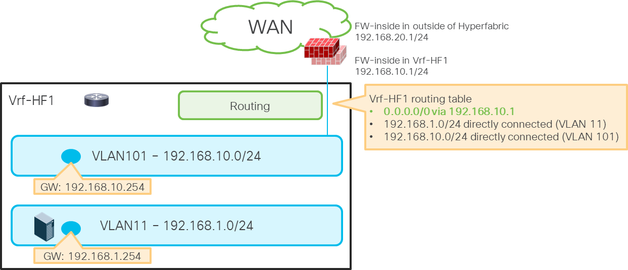
Perimeter firewall insertion
Insert Firewall Between VRF Instances
The figure below illustrates a set of logical networks designed to insert firewalls between the external VRF instance (Vrf-HF1) and the internal VRF instance (Vrf-HF2). When a server in Vrf-HF2 talks to another server or the external network in Vrf-HF1, the firewall is inserted based on routing. Two firewall logical interfaces are connected through logical networks with SVIs (VLAN101 and VLAN102 in this example). Static route or dynamic routing in both VRF instances needs to be configured accordingly to insert the firewalls between VRF instances.
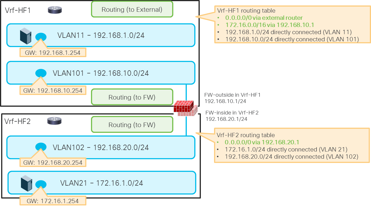
Example: firewall between VRF instances
This section explains the following two routing options that are currently available on Cisco Nexus Hyperfabric:
· Static Route
· Dynamic Routing (BGP)
Both options are available with routing next hops connected through Layer 3 interfaces (routed interfaces and routed sub-interfaces) and Layer 2 interfaces (host interfaces and port channels). This document focuses on design examples with Layer 2 interfaces because the use of Layer 2 interfaces is common for Layer 4 to Layer 7 device connectivity. Although both host interfaces and port channel interfaces are valid options, this section uses a host interface in the illustrations. For the physical connectivity option, see Physical Design Options.
For details on how to configure a static route and BGP on Cisco Nexus Hyperfabric, see Cisco Nexus Hyperfabric – Configure Logical Networks -> Add a static route and Cisco Nexus Hyperfabric – Configure BGP.
The figures below give an example of a static route configuration and its behavior.
Even though the static route configuration doesn’t contain specific switch or interface information, the static route will be programmed on the required switches automatically.
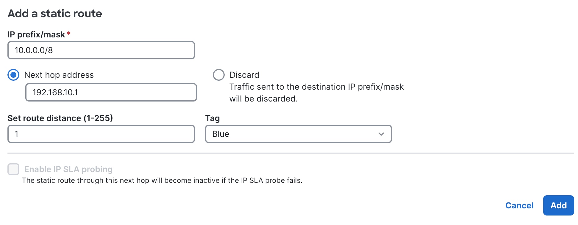
Static route configuration in Cisco Nexus Hyperfabric
When the next hop is connected through a Layer 2 interface using a logical network with an SVI, the switches that have the logical network have the static route entry. Even if the next hop is not directly connected to a switch, the switch can learn the next hop address location through the other switch where the next hop is directly connected.
Static routes in Cisco Nexus Hyperfabric (through a logical network)
The figure below illustrates a traffic flow example. When LF04 receives the traffic destined to 10.0.0.0/8, it will be forwarded to LF01 where the next-hop IP address 192.168.10.1 is observed locally.
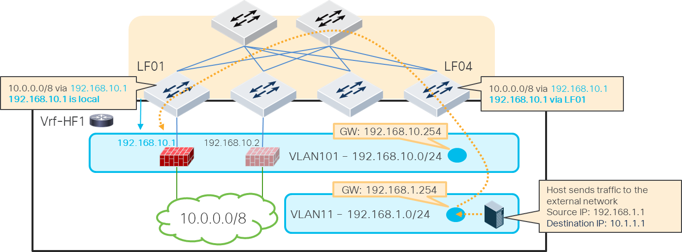
Traffic flow example (FW1 under LF01 is active)
When active-standby switchover happens, the firewall active IP address moves as the new active firewall (previously standby) takes over the active IP address typically by sending GARP. As a result, the location of the static route next hop IP address is changed accordingly as illustrated below.
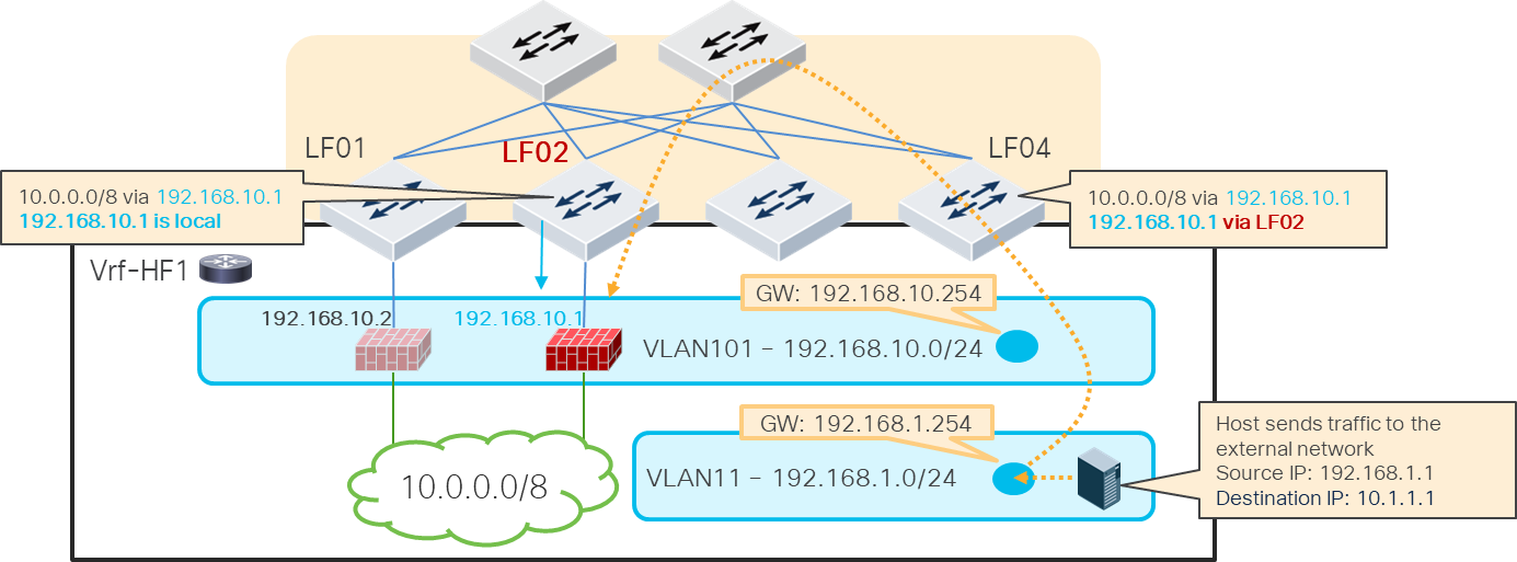
Traffic flow example (FW2 under LF02 becomes active)
The figures below explain a topology and configuration examples for BGP peer through Layer 2 interfaces. BGP peerings are established between the active firewall and loopbacks on the Cisco Hyperfabric switches. Although this example uses spine switches for BGP peerings, any switch in the fabric can be a BGP source.
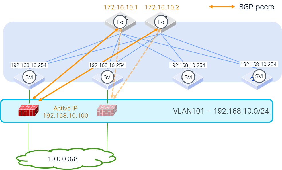
BGP peers from host port (FW1 under LF01 is active)
The figures below illustrate how routes are exchanged. Because spine switches establish the BGP peerings with the active firewall, spine switches learn the external route and redistribute the route within the fabric. The other switches, such as LF04 in this example, learn the external route (10.0.0.0/8 from 192.168.10.100 in this example). Even if the next hop is not directly connected under LF04, LF04 can learn the next hop address location through the other switch where the next hop is directly connected.
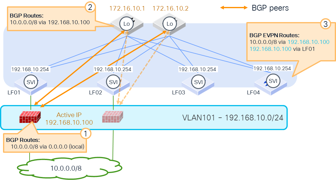
How external routes are learned
The internal subnets such as logical network subnets are advertised through the spine switches in this example. The key point here is that the next-hop IP address of the route is not a spine switch’s IP address. It’s rewritten to the SVI of the logical network where the firewalls are located. In this example, the active firewall learns 192.168.1.0/24 with the next-hop 192.168.10.254, which is reachable as long as the firewall is in the logical network even if the active firewall moves to another location in the fabric.
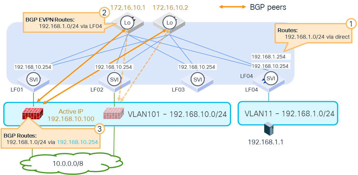
How internal routes are advertised
Because of this behavior, the benefit of this design is that even during active-standby switchover or virtual machine movement, as long as it’s within the same logical network, the BGP peering remains intact and the change of the route is minimized. In this example, although the location of 192.168.10.100 is changed, the BGP peer is still between the loopback addresses of the spine switches and the active firewall.
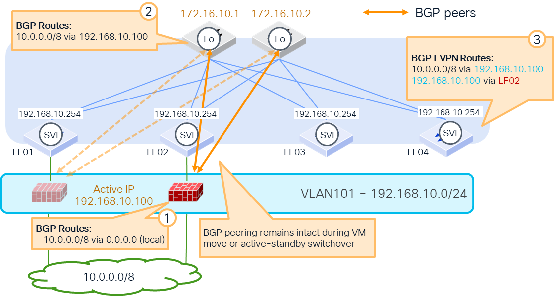
BGP peers from host port (FW2 under LF02 becomes active)
The following items are the prerequisites to establish the BGP peerings between the loopback addresses and the active firewall:
· Cisco Nexus Hyperfabric configuration:
o Logical network with SVI and its VLAN membership configuration, which is where the firewall logical interfaces reside (in this example, VLAN101 with 192.168.10.254)
o Loopback IP addresses on switches (in this example, 172.16.10.1 and 172.16.10.2 on spine switches)
· Firewall configuration: static routes to reach the BGP peers that are the loopback IP addresses on Cisco Nexus Hyperfabric (in this example, static routes 172.16.10.1 and 172.16.10.2 through 192.168.10.254, which is the SVI of the logical network)
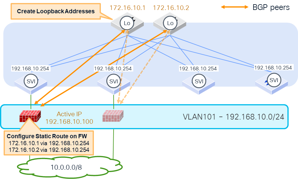
Prerequisites
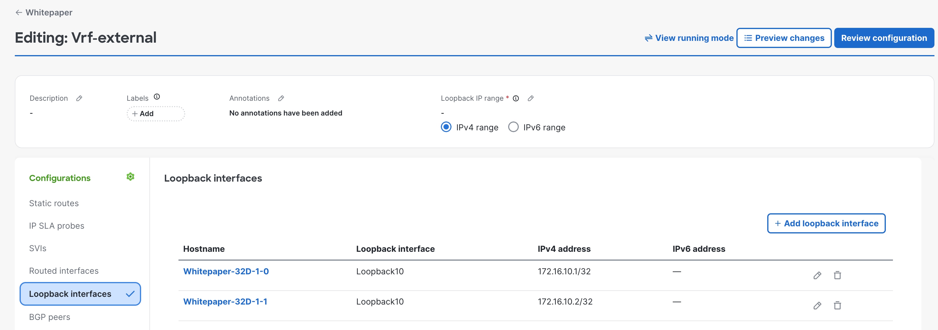
Prerequisite configuration: Create loopback interfaces on the switches
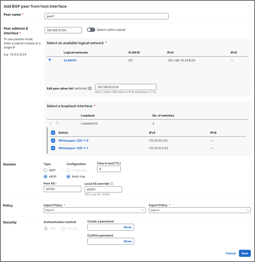
BGP configuration: Configure the BGP peer from the host interface
BGP import and export policies
This section explains a consideration of the default export and import policies.
When the default import and export policies are used, Cisco Nexus Hyperfabric doesn’t advertise routes to external BGP peers if the routes are dynamically learned from an external BGP peer, which is to prevent unintended routing loops. Because of this behavior, you might need to use custom BGP import and export policies in the case of Layer 3 firewall insertion between VRFs using BGP.
The figure below illustrates an example. If the internal subnet in Vrf-HF2, such as 172.16.1.0/24, needs to be reachable from the external network behind Vrf-HF1, 172.16.1.0/24 needs to be advertised to the external network from Vrf-HF1. Because 172.16.1.0/24 in Vrf-HF1 is learned using BGP from the firewall, it’s not advertised to the external router through BGP if the default import and export policies are used.
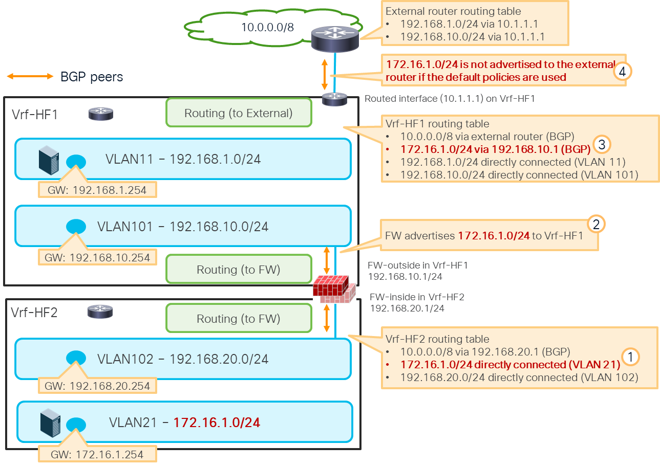
Custom BGP import and export policies are required to advertise an internal subnet learned through the firewall
Another consideration of the default import and export policies is that it doesn’t advertise the default route (0.0.0.0/0 for IPv4 and ::0/0 for IPv6) to the external BGP peer. For details about BGP policies and how to configure, see: