
Cisco Nexus Hyperfabric — Configure Port Channels
Port channels
The port channel is a powerful networking technology used to combine multiple physical Ethernet links into a single logical link. A basic port channel aggregates links from a single switch, while a multi-chassis port channel aggregates multiple physical links across a pair of switches, creating a single logical link.
A multi-chassis port channel creates redundancy for higher availability. You can configure one of the switches as active and the other as passive, then have the passive switch take over for the active switch when necessary.
Each port channel is identified a 10-bit number that is unique to the fabric. Every member link in a port channel is assigned the same identifier. This number is generated automatically, or you can specify the number when you create a port channel.
Guidelines for port channels
- Nexus Hyperfabric supports Link Aggregation Control Protocol (LACP) — active.
- The LACP timer rate is 3 times of 30 seconds.
-
Nexus Hyperfabric supports these port channel topologies:
- Basic port channels, in which all physical links connect one device to another device.
- Multi-chassis port channels, in which physical links across more than one switch are aggregated to connect to another device.
- You can mix and match different supported switch models.
Limitations for port channels
- A port channel's ID must be unique within the fabric.
- All member ports of a port channel must have the same port speed and MTU.
- A port channel supports a maximum of four member ports and spans a maximum of two switches. The switches can be either two leaf switches or two spine switches, but not a spine and a leaf switch.
- A switch may act as a peer in more than one port channel only if the other peer switch is the same for each port channel.
- You cannot mix different port channel pairs on the same switch.
- If you have a Cisco UCS C-series rack server with a virtual interface card (VIC), link layer discovery protocol (LLDP) or link aggregation control protocol (LACP) might not work without enabling the Physical NIC Mode. However, if you enable the Physical NIC Mode, ensure that your server is using a Cisco IMC release that contains the fix for CSCwk79922. For basic information about LLDP and LACP, see the "Terminology" section of the Cisco Nexus Hyperfabric—Getting Started document.
Examples of supported and unsupported port channel topologies
| Supported topologies | |
|---|---|
|
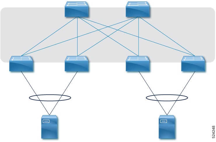
This example shows two port channels:
|
|
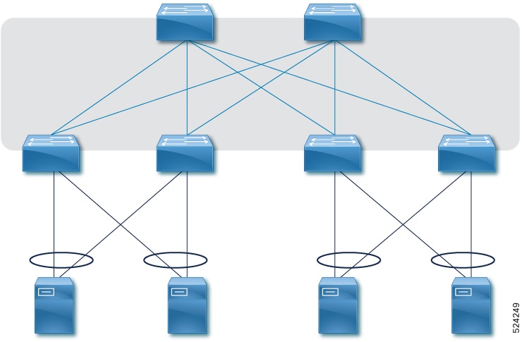
This example shows four port channels:
|
|
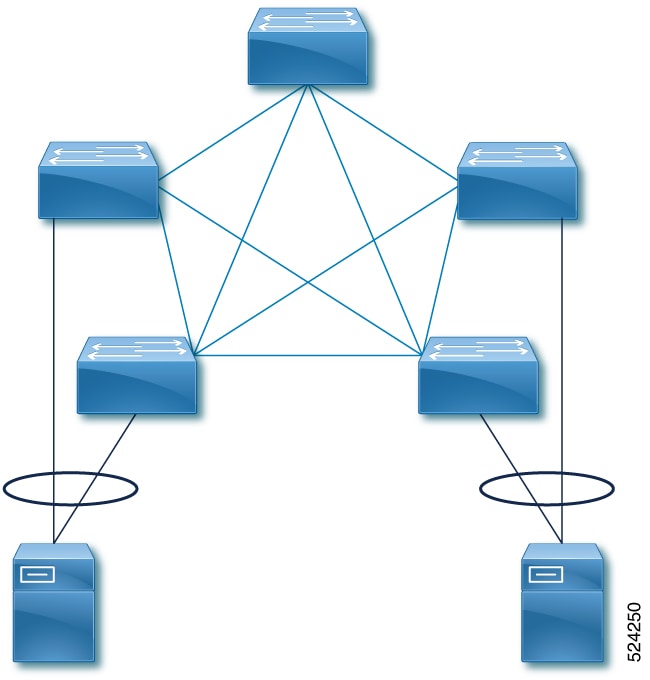
This example shows two port channels:
|
| Unsupported topologies | |
|---|---|
|
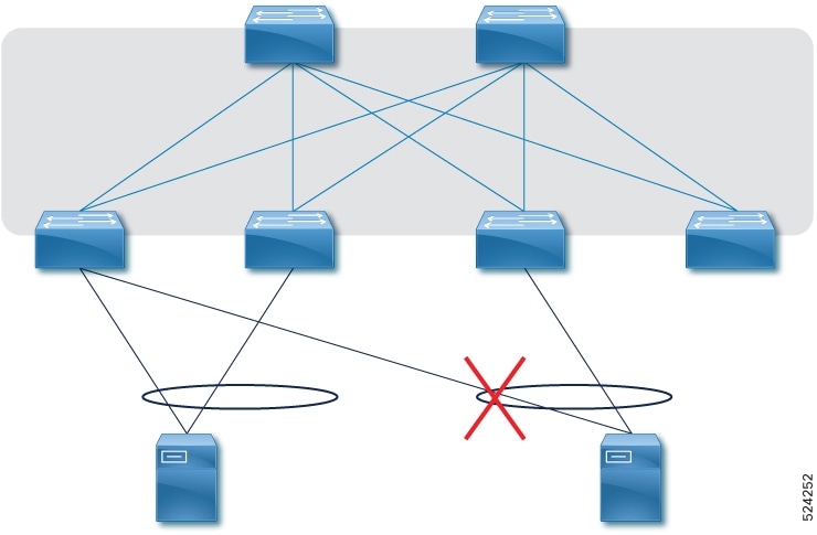
A port channel spans a maximum of two leaf switches. In this example, four leaf switches are aggregated. |
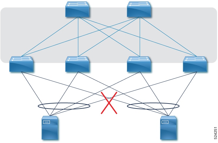
|
A leaf switch may act as a peer in more than one port channel only if the other peer switch is the same for each port channel. In this example, Leaf1 and Leaf2 are aggregated for one port channel, and Leaf1 and Leaf3 are aggregated for another. |
|
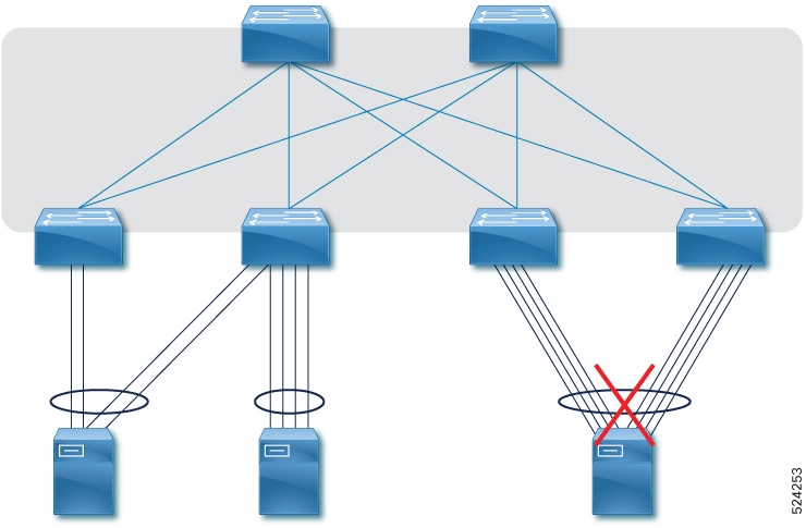
A port channel supports a maximum of four member ports. In this example, the third port channel has eight aggregated ports. |
Configure a port channel
A port must have the Unused role for you to be able to select it as member of a port channel. After you add a port channel, the role of the selected ports changes to Port channel and you cannot change the role in the port configuration page.
If you want to configure spanning tree protocol (STP) for the ports of a port channel, see the Configure logical networks document.
Follow these steps to configure a port channel.
Step 1 | Select Fabrics, then select the desired fabric. |
Step 2 | If the fabric is not in the edit mode, select Switch to edit mode. |
Step 3 | In the Attachments area, select Port channel. A table of existing port channels appears. 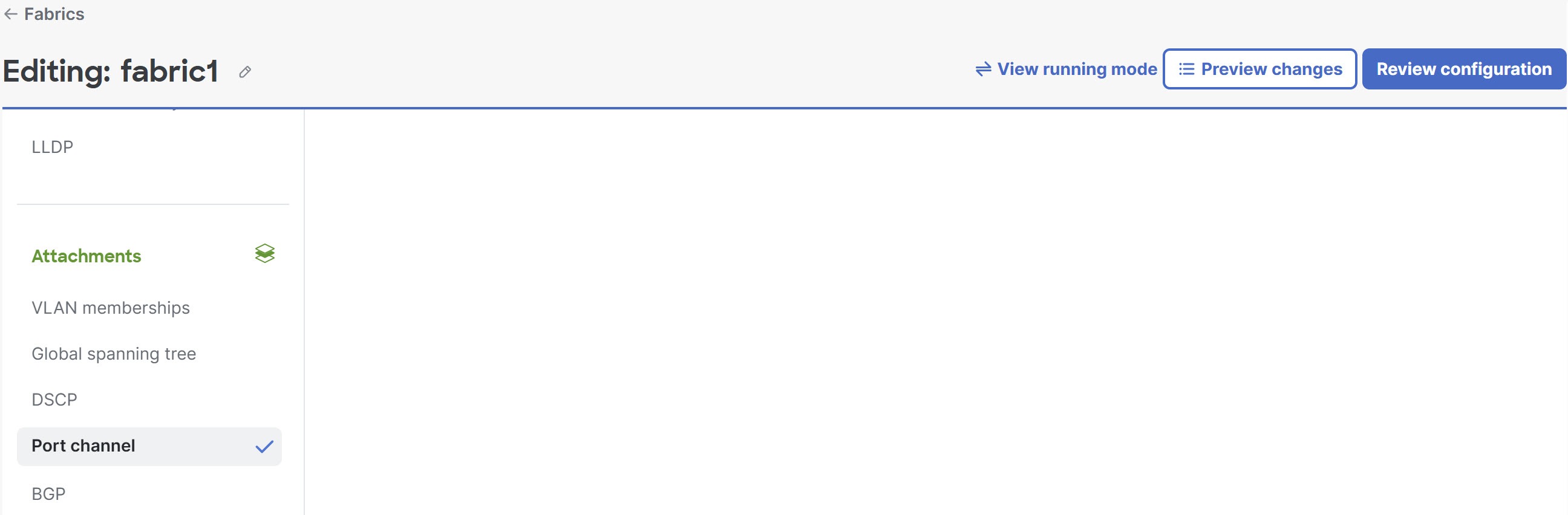
|
Step 4 | Select + Add port channel and follow these substeps. 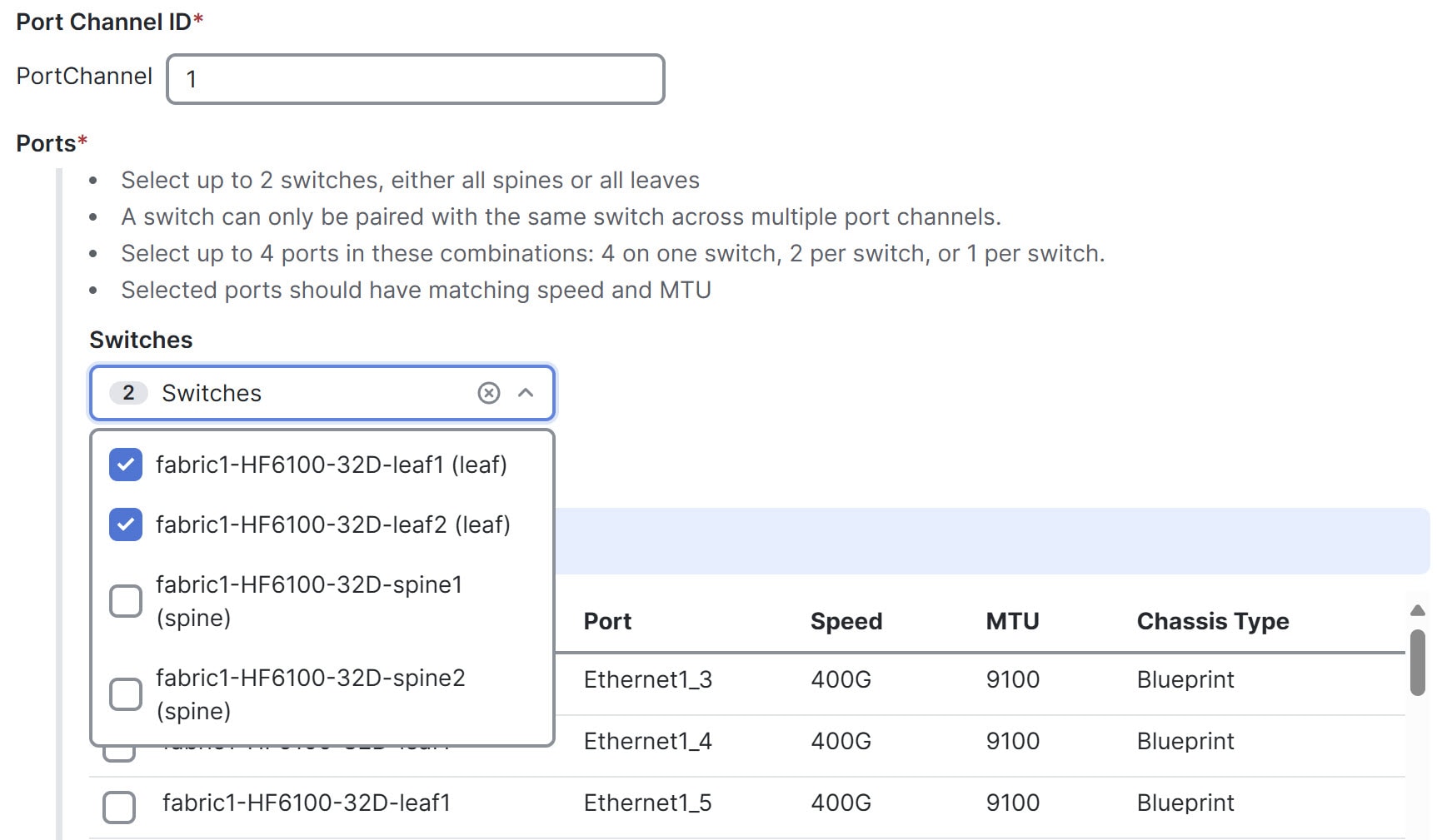
|
Step 5 | Select Save. |
Finish and commit your changes
Your changes are not applied to the fabric until you review, commit, and push them.
 Note
NoteFor a more detailed description of this procedure, see "Workflow for making changes to the fabric" in Cisco Nexus Hyperfabric—Getting Started.
Follow these steps to finish and commit your changes.
Step 1 | Select Review configuration. 
|
Step 2 | Verify your changes in the review list. |
Step 3 | Select Comment and push. |
Step 4 | In the Comment before pushing configuration dialog box, enter the reason for the change. |
Step 5 | Select Push configuration. |
View port channel properties
You can view port channel properties such as member ports, link status, topology, labels, annotations, LACP status, and LACP counters.
Follow these steps to view port channel properties.
Step 1 | Select Fabrics, then select the fabric whose properties you want to view. |
Step 2 | In the Attachments area, select Port channel. A table of existing port channels appears. 
The table shows this information for port channels:
The table shows this information for ports:
|
Step 3 | Expand a port channel to see the related ports and select the name of a port to view information about that port. 
|
Step 4 | While you are viewing the information about a port channel, you can select Edit port channel to edit that port channel. |
Step 5 | Select a port channel's name to view detailed information about that port channel, such as LACP status, link status, and switch status. 
|