
Cisco Nexus Hyperfabric — Configure BGP
Border Gateway Protocol (BGP)
BGP is a dynamic routing protocol used to exchange routing information between different autonomous systems (AS) on the internet. You should configure BGP if your network needs to connect to multiple external networks or support complex, scalable routing. BGP enables automatic route updates and adapts quickly to network changes, making it essential for medium to large networks that require high availability, redundancy, and flexibility.
When BGP peering is established between devices, they share full routing tables initially and then exchange updates only for changed routes. BGP policies allow you to control which routes are advertised or accepted, helping you manage network traffic according to your organization’s needs.
Compared to static routing—which is simple but lacks scalability and requires manual updates—BGP is a robust solution that supports dynamic growth and reliability.
To configure and apply your changes, ensure that you are in edit mode and that you commit your changes.
BGP import and export policies
BGP import and export policies consist of rules and configurations that determine which routing information is selected, advertised, and accepted between BGP peers.
BGP import policy applies to routes received from external BGP peers. BGP export policy applies to routes sent to external BGP peers.
- Default import and export policies are predefined and cannot be changed. The default policy acts as a template that contains specific rules.
-
If you use both default import and export policies, these routes are not advertised to the external peer.
- externally learned routes
- default route
- internal endpoint IP addresses
To view the default import or export policies, navigate to the Fabrics page. In the Attachments area, choose or .
Default import policy
|
Match |
Set |
Action |
|---|---|---|
|
All |
Community 64511:99 |
Permit |
Default export policy
|
Match |
Set |
Action |
|---|---|---|
|
Community 64511:99 |
- |
Deny |
|
Route tag Black |
- |
Deny |
|
IPv4 Prefix 0.0.0.0/0 (Exact) |
- |
Deny |
|
IPv6 Prefix ::/0 (Exact) |
- |
Deny |
|
Community 64510:* |
- |
Permit |
|
IPv4 Prefix 0.0.0.0/0 (Exact or longer) 32 |
- |
Deny |
|
IPv6 Prefix ::/0 (Exact or longer) 128 |
- |
Deny |
|
All All conditions are matched |
- |
Permit |
- When you add a static route, the Discard option in the Add Static Route page, matches Match Route tag Black, Deny rule in the default export policy. See Add a static route.
- Route-tag rules can also match tags configured on Layer 3 logical-network, routed-interface, routed-subinterface, and loopback IP routes.
- The rule Community: 64510:* is used to advertise one or more static routes to an external network.
-
In the default export policy, certain rules prevent advertisement of the default route and internal endpoint IP addresses (host routes) to the external network.
- Match 0.0.0.0/0 (Exact), Deny
- Match ::/0 (Exact), Deny
- Match 0.0.0.0/0 (Exact or longer) 32, Deny
- Match ::/0 (Exact or longer) 128, Deny
- Because the route imported from the external BGP peer has the rule Community: 64511:99 set by the default import policy, the route is not exported to a BGP peer because of the Deny rule in the default export policy.
Use route tags to control BGP route advertisement
A route tag is color-based metadata applied to a static route or to an IP address on a Layer 3 logical network (SVI), routed interface, routed subinterface, or loopback interface. Cisco Nexus Hyperfabric associates the tag with the route as an internal extended community.
In a BGP export policy, use Route-tag as the match type to permit or deny routes with a selected tag. For example, a rule that matches the Blue route tag can advertise all Blue-tagged static, SVI, routed-interface, routed-subinterface, and loopback routes to the selected BGP peer.
Create a BGP import policy
Follow these steps to create a BGP import policy.
Step 1 | Choose Fabrics, then select the fabric you want to configure a BGP import policy for. |
Step 2 | In the Attachments area, choose . |
Step 3 | Select + New policy. 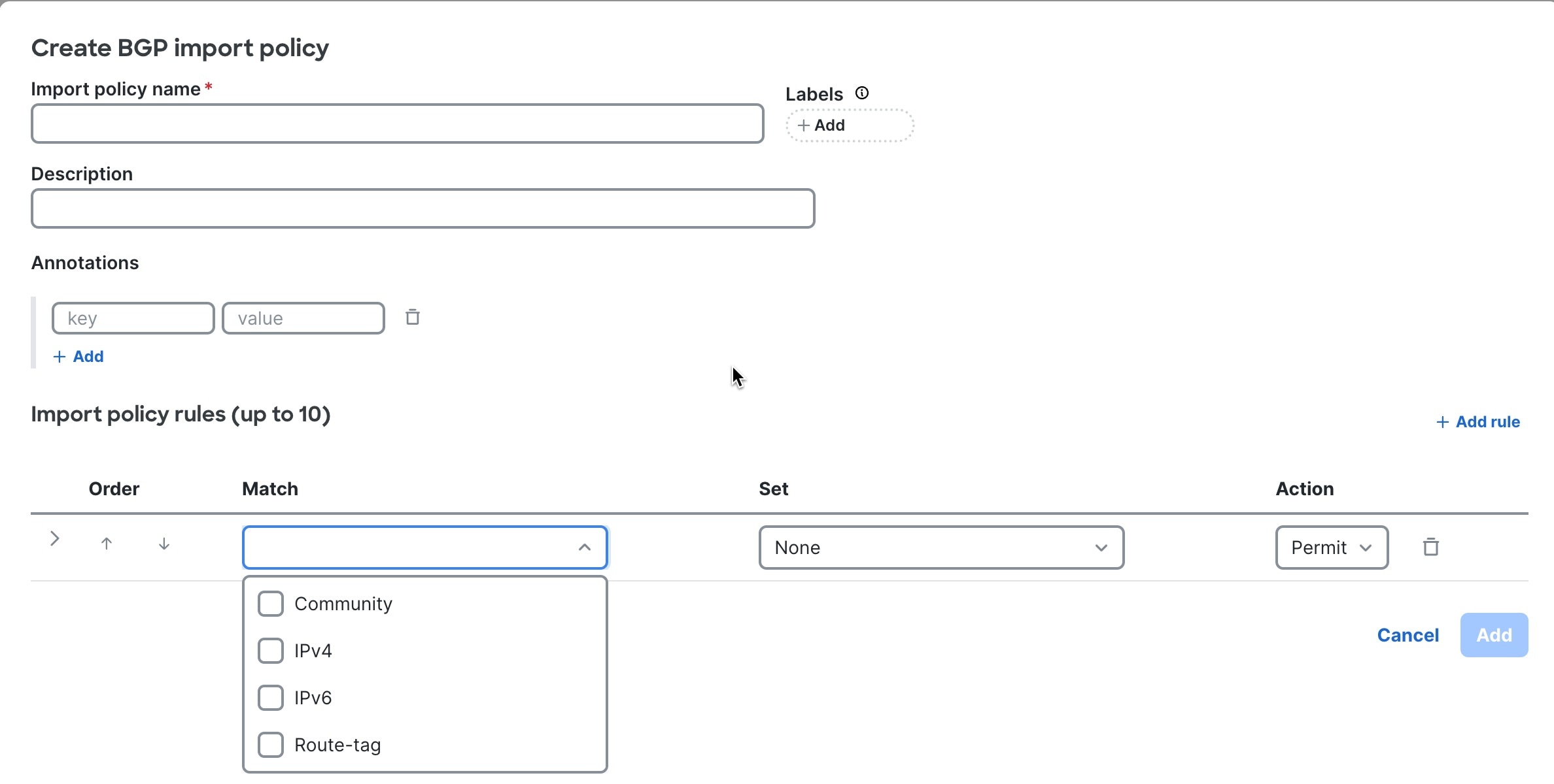 |
Step 4 | Enter BGP import policy details.
|
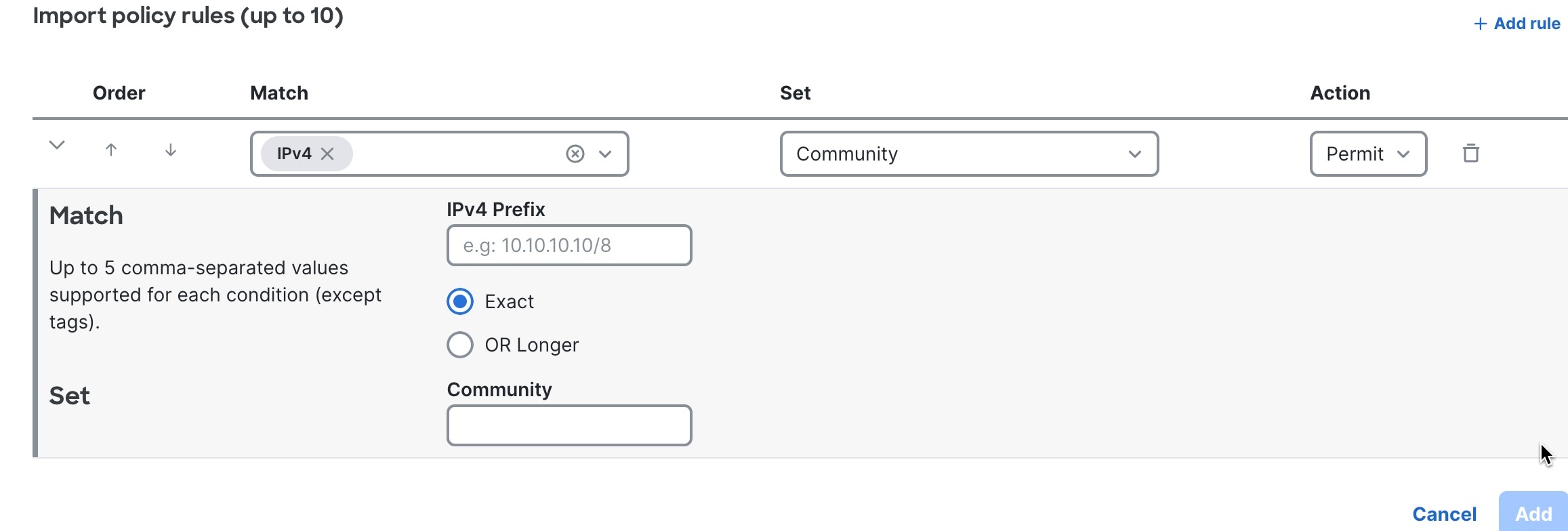
Step 5 | Enter BGP import policy rules.
|
Step 6 | Select Add. |
Create a BGP export policy
Follow these steps to create a BGP export policy.
Step 1 | Choose Fabrics, then select the fabric you want to configure a BGP export policy for. |
Step 2 | In the Attachments area, choose . |
Step 3 | Select + New policy. 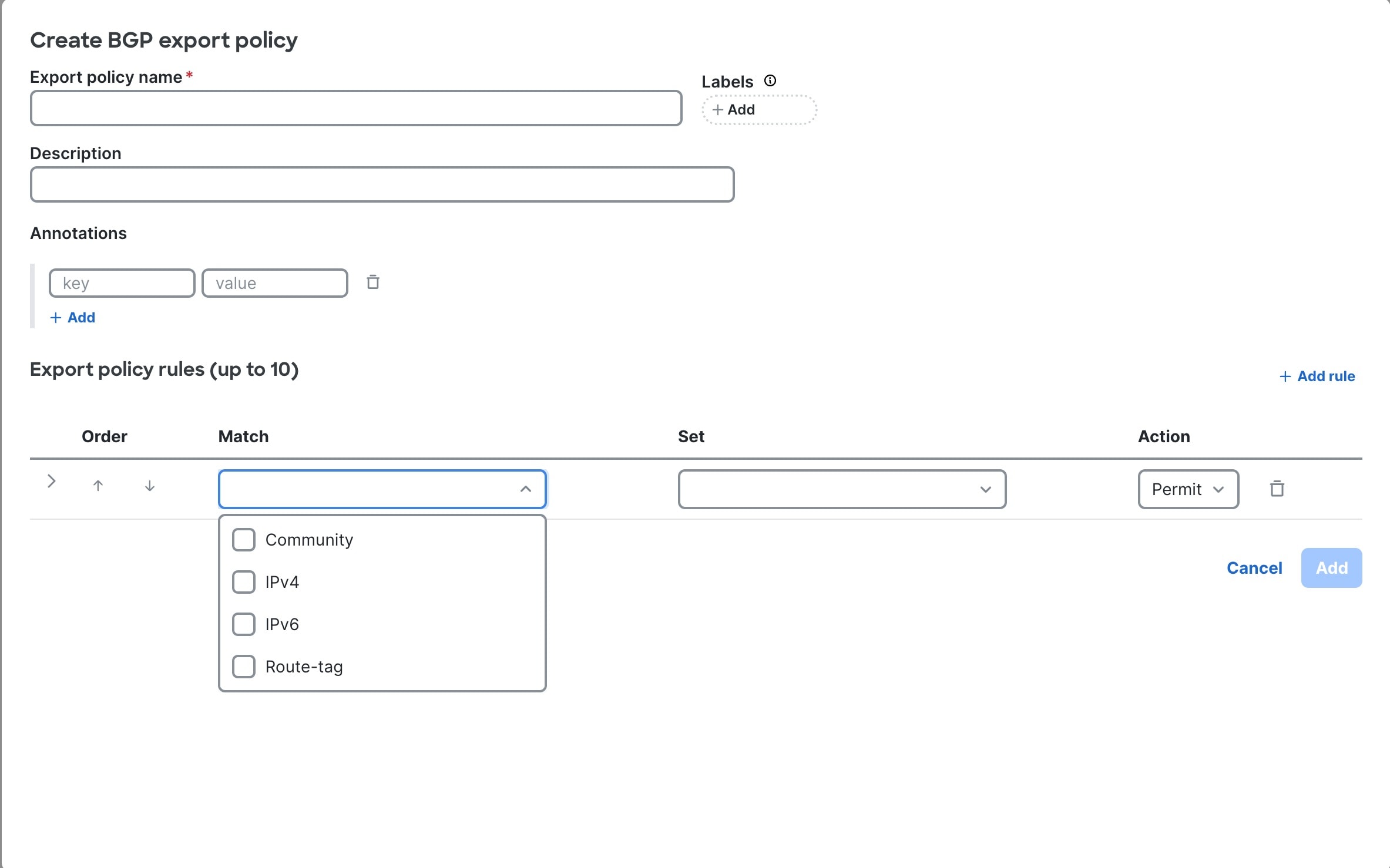
|
Step 4 | Enter BGP export policy details.
|
Step 5 | Enter BGP export policy rules.
|
Step 6 | Select Add. |
BGP peering
Within the Cisco Nexus Hyperfabric, BGP peering can be broadly categorized into two types:
- BGP peering from routed interfaces (northbound peering): This peering type establishes BGP sessions via routed or routed sub-interfaces. It typically connects the network fabric to the external network behind physical devices.
- BGP peering from host interfaces (southbound peering): This peering type establishes BGP sessions between the network fabric and devices within a data center's logical network subnet. This approach commonly uses virtual devices such as virtual routers, virtual firewalls, or containers. It provides greater control and insight into the movement of traffic for individual hosts.
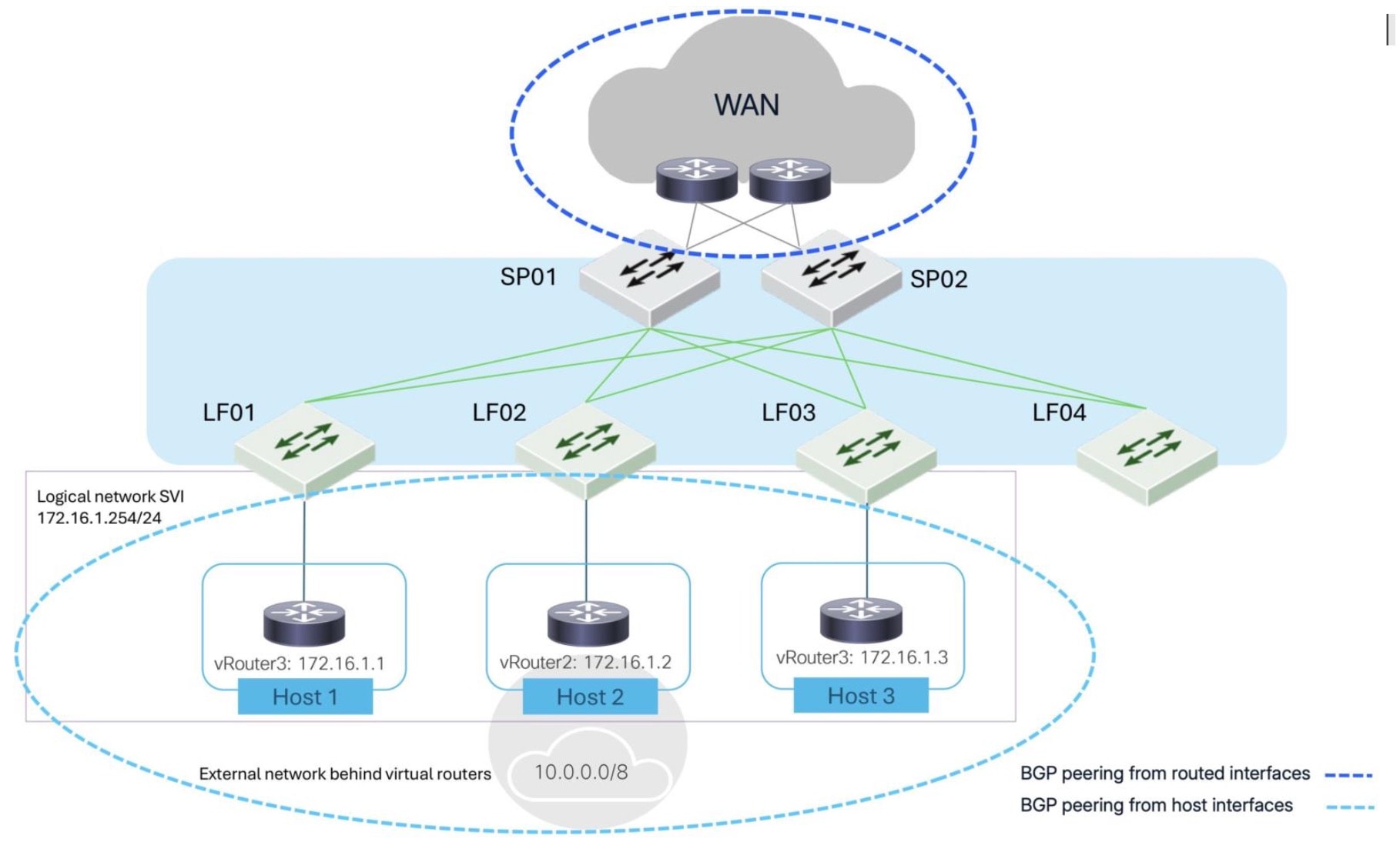
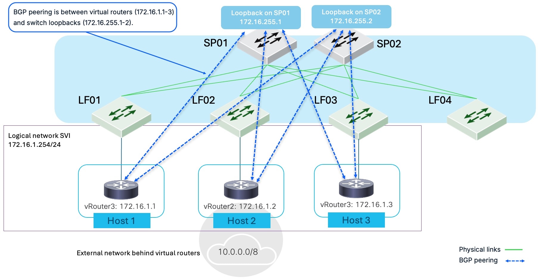
The figure illustrates a network fabric. SP01 and SP02 function as spine switches, providing core connectivity, including to a Wide Area Network (WAN). Leaf switches LF01, LF02, LF03, and LF04 connect to both spines for redundancy and load balancing. Virtual routers (vRouter1, vRouter2, vRouter3), representing Host 1, Host 2, and Host 3, connect to leaf switches LF01, LF02, and LF03.
The figure highlights the two types of BGP peering. "BGP peering from routed interfaces" (dashed blue line) connects the virtual routers to a logical network SVI (172.16.1.254/24) and an external network (10.0.0.0/8). "BGP peering from host interfaces" (dashed light blue line) directly connects the virtual routers to the leaf switches. This configuration demonstrates BGP peering relationships within the fabric and with external networks.
 Note
NoteAlthough the figure shows spines and leaves, either type of BGP peering can occur on devices other than spines or leaves.
Examples of BGP peering from host interfaces
These examples illustrate the concept and resilience of BGP peering from host interfaces.
In this example, multiple virtual routers (vRouter1, vRouter2, vRouter3) on different hosts are within the same logical network. These virtual routers establish BGP peering with the loopback interfaces of the spine switches (SP01 and SP02), which form the core of the network fabric. This demonstrates initial BGP peering from host interfaces that are connected to external devices within a logical network.
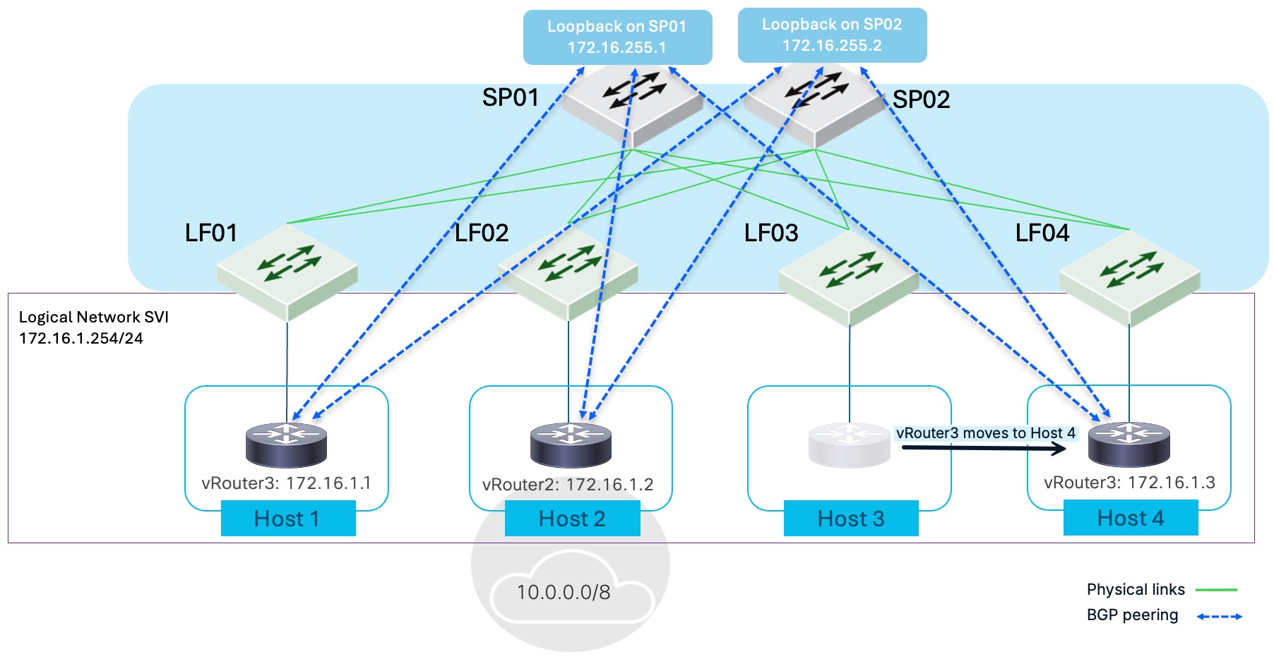
This example highlights a key advantage of this design. It shows vRouter3 migrating from Host 3 to Host 4, a change in its physical location within the fabric. The BGP peering remains unchanged, illustrating the stability and mobility benefits of BGP peering from host interfaces. The BGP sessions remain active and unaffected by the virtual device's physical relocation, ensuring continuous routing and connectivity for its services.
Configure BGP peering from routed interfaces
BGP peering from routed interfaces, often referred to as northbound peering, involves establishing BGP sessions between switches using their routed interfaces. This type of peering connects the fabric to external networks. It is used for getting traffic in and out of the network.
Step 1 | Navigate to the BGP peers area for a specific route table (VRF).
|
Step 2 | Enter the VRF's local autonomous system (AS).
|
Step 3 | Choose . |
Step 4 | For Peer name, enter a name for the new BGP peer. |
Step 5 | Enter BGP peer address and interface details.
|
Step 6 | Enter BGP peering details.
|
Step 7 | In the Policy area, select an Import policy and an Export policy from the drop-down list or keep the defaults. These policies are defined in Create a BGP import policy and Create a BGP export policy. |
Step 8 | (Optional) In the Security area, select an authentication method and enter the credentials. |
Step 9 | Select Save. |
 and enter the VRF local AS.
Configure BGP peering from host interfaces
BGP peering from host interfaces establishes BGP sessions between the fabric and endpoints. This peering type uses loopbacks to maintain stable sessions. It provides granular control and visibility of host-level routing, helping you manage traffic flows and policies at the network edge.
Ensure these configurations exist prior to configuring a BGP peer from host interfaces:
- the VRF where you want to add a BGP peer
- a logical network with a Switch Virtual Interface (SVI) on the VRF
- a loopback interface on a switch to host the BGP session
- ports assigned with the host role, and
- port VLAN membership for the logical network.
Step 1 | Navigate to the BGP peers area for a specific route table (VRF).
|
Step 2 | Enter the VRF's local AS.
|
Step 3 | Choose . |
Step 4 | Enter BGP peering details.
|
Step 5 | Configure the BGP peering session.
|
Step 6 | In the Policy area, select an Import policy and an Export policy from the drop-down list or keep the defaults. These policies are defined in Create a BGP import policy and Create a BGP export policy. |
Step 7 | In the Security area, select an authentication method and enter the credentials. |
Step 8 | Select Save. |
View all BGP sessions and policies in a fabric
You can quickly find BGP peering sessions and policy information details for an entire fabric:
- Peering sessions from routed interfaces (northbound peering): View these details to confirm that routed interfaces are successfully establishing BGP sessions with the fabric, and to verify their associated VLANs and specific switch locations. This view is crucial for ensuring dynamic route learning, confirming route advertisements, and troubleshooting connectivity with external networks.
- Import policies: Use these details to understand and verify which routes are being accepted from BGP neighbors into the fabric's routing tables. This ensures that only desired routes are learned, preventing routing table pollution, enforcing security, and correctly directing incoming traffic.
- Export policies: Use these details to understand and verify which routes the fabric is advertising to its BGP neighbors. This is crucial for controlling what information is shared externally, preventing accidental route leakage, and influencing how traffic is routed back into the fabric.
Step 1 | Choose Fabrics, then select the fabric you want to see BGP peering information for. |
Step 2 | In the Attachments area, choose BGP. |
Step 3 | Select the type of information you want to see. |
View BGP peer details
When you view BGP peer details, you can actively monitor several key aspects of your fabric’s BGP operations:
- Peer details: Check whether each BGP session is established and running smoothly. This allows you to quickly verify connectivity with your BGP peers and troubleshoot any issues with session establishment.
- Received routes: Review the routes your device learns from BGP peers. These routes include important attributes such as AS path, next hop, and local preference. By inspecting these details before import policies are applied, you can make sure your device receives and processes routes from neighbors correctly.
- Advertised routes: Examine the routes your device advertises to its BGP peers. This helps you detect unusual or unauthorized routes. It enables you to spot potential route leaks or hijacks and control which routes your device shares to optimize traffic flow.
By actively reviewing these details, you can validate BGP connectivity, resolve routing issues, and maintain strong, effective routing policies across your fabric.
This procedure describes how to navigate to BGP peer details from the fabric level. To view BGP peers for a specific VRF, in the Logical Network area, choose .
Step 1 | Choose Fabrics, then select the fabric you want to see BGP peering information for. |
Step 2 | In the Attachments area, select BGP. |
Step 3 | In the BGP peers table, select the peer name. |
Step 4 | Select the type of information you want to see: Peer details, Received routes, or Advertised routes. |
Manage BGP peers
Follow these steps to edit or delete a BGP peer.
Step 1 | Navigate to the route table of the BGP peer you want to edit or delete.
|
Step 2 | Depending on how the BGP peer is configured, select from routed interface or from host interface. |
Step 3 | Edit the BGP peer.
|
Step 4 | Delete the BGP peer.
|
Finish and commit your changes
Your changes are not applied to the fabric until you review, commit, and push them.
NoteFor a more detailed description of this procedure, see "Modify a fabric" in Cisco Nexus Hyperfabric—Getting Started.
Follow these steps to finish and commit your changes.
Step 1 | Select Review configuration. 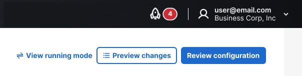
|
Step 2 | Verify your changes in the review list. |
Step 3 | Select Comment and push. |
Step 4 | In the Comment before pushing configuration dialog box, enter the reason for the change. |
Step 5 | Select Push configuration. |
Common troubleshooting scenarios
Q: I have configured a BGP from host interfaces session, but I don't see any BGP state. Why doesn't it show BGP session states if it's not fully established?
A: BGP sessions configured from host interfaces operate in a passive listen-only mode. Therefore, you will only see BGP session states for sessions that are actively established by neighbors initiating the sessions.
Additionally, BGP from host interfaces is designed to scale to large numbers of neighbors, particularly for Container Network Interfaces (CNIs). This passive mode configuration simplifies the BGP setup and makes it easier to maintain within Cisco Nexus Hyperfabric environments.
Q: I have configured a BGP neighbor from a host interface (a virtual firewall). However, I do not see any active connections from the virtual firewall, and the firewall shows its BGP state as IDLE. Why is this happening?
A: Nexus Hyperfabric uses a loopback interface as the BGP interface when configuring BGP from host interfaces. Therefore, if you are running in external BGP (eBGP) mode, you must configure the BGP peer for multi-hop.
If your BGP neighbor is in the IDLE state, it is a good indicator that the BGP peer may be unable to establish a session because the neighbor is not directly connected. By default, eBGP has a hop limit of 1. In this case, you must enable eBGP multi-hop mode on your BGP peer and specify a hop count greater than 1 to allow the session to establish.