Deploying and Verifying Cisco Nexus One Fabric Connectivity and Policy Between ACI and NX-OS Fabrics
Available Languages
Bias-Free Language
The documentation set for this product strives to use bias-free language. For the purposes of this documentation set, bias-free is defined as language that does not imply discrimination based on age, disability, gender, racial identity, ethnic identity, sexual orientation, socioeconomic status, and intersectionality. Exceptions may be present in the documentation due to language that is hardcoded in the user interfaces of the product software, language used based on RFP documentation, or language that is used by a referenced third-party product. Learn more about how Cisco is using Inclusive Language.
- US/Canada 800-553-2447
- Worldwide Support Phone Numbers
- All Tools
 Feedback
 Feedback
What are the benefits of architecture?
High level architecture of the deployment
Hardware and software versions
Example #1 – ACI Fabric to NX-OS Fabric (ND Managed)
Infrastructure Configuration for Underlay and Overlay
Overlay Networking and Use Cases
| Date |
Change |
Location |
| 2026-08-20 |
Initial publication |
This document |
This document will cover in detail the requirements, configuration steps, and verification details for deploying the Cisco Nexus One fabric architecture. The primary goal is to interconnect Cisco ACI Fabrics, and NX-OS fabrics using standards based VXLAN EVPN peering leveraging border gateways. While this document’s primary goal is to use ACI and NX-OS fabrics, it is important to note that you could connect ACI to any standards based VXLAN EVPN fabric deployment. Therefore, the steps outlined in this white paper aim to illustrate how that configuration is deployed independently on each fabric. For seeing how both ACI and NX-OS configuration can be automated centrally from Nexus Dashboard, please see <insert 4.2 whitepaper link when ready>.
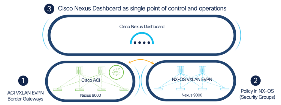
The Cisco Nexus One Fabric architecture is comprised of a few key components:
● Nexus Dashboard. Nexus Dashboard will act as a centralized and normalized control point of all operations over Cisco fabrics interconnected with this architecture regardless of the underlying implementation differences in each fabric. In this paper, we focus on ACI and NX-OS fabrics. In ND release 4.1, and for this example, Nexus Dashboard will not provision the APIC configuration required to build the end-to-end connectivity but will handle the NX-OS configuration. In Nexus Dashboard release 4.2, Nexus Dashboard can be the single control point for all configuration, and operations/telemetry across both fabrics. Examples of this will be coming soon in an updated publication.
● VXLAN EVPN Border Gateway. It enables scalable interconnectivity between multiple VXLAN fabrics that can participate in VXLAN EVPN Multi-Site with Border Gateways based on the IETF draft “draft-sharma-bess-multi-site-evpn-05.
● VXLAN Security Groups. It provides a consistent security enforcement between the fabrics/sites via EVPN Group Policy ID Extended Community based on the IETF draft “draft-lrss-bess-evpn-group-policy-02” and VXLAN Group Policy Option based on the IETF draft “draft-smith-vxlan-group-policy-05”. For end-to-end security enforcement, each fabric should support the same or similar capability within itself as well.
To support this architecture, several features and enhancements were added into the Cisco Data Center networking portfolio to support this:
● Cisco ACI and border gateways. Beginning in ACI release 6.1, an additional leaf role was added: border gateway leaf. This switch role allows the termination of internal ACI networking and policy into standards based VXLAN EVPN. The Nexus One fabric architecture leverages these border gateways to interconnect to other VXLAN EVPN fabrics.
● VXLAN Group Policy Option. This functionality allows Security Group Tags (SGT) to be added into EVPN routes, as well as into the VXLAN header for data plane identity and policy enforcement. For detailed information, please refer to the VXLAN GPO whitepaper.
What are the benefits of architecture?
VXLAN EVPN has always enabled seamless extension of Layer-2 and Layer-3 networks across switches in the same fabric, and across fabrics via VXLAN EVPN Multi-Site. With the ability to interconnect ACI fabrics to other VXLAN EVPN fabrics, especially NX-OS, we now have the ability to apply this architecture in a way that will work regardless of the underlying differences within each site. This unlocks some critical use cases:
● Co-existence of multiple architectures and operating models – It is common for there to be use cases in deploying different data center architectures and operating models. A customer may choose to deploy ACI as their primary datacenter fabric, leveraging deep automation and software defined networking policies. However, that same customer may opt to deploy NX-OS fabrics in another site where a traditional networking approach with CLI and Nexus Dashboard automation might be a better fit. There are also scenarios where mergers and acquisitions of other companies happen where different architectures and deployments were at play. In those cases, it is critical to be able to interconnect them if the business requires it.
● Ease of migration to or from different architectures – With the ability to extend VXLAN EVPN across architectures, it can make migrating to or from an instance of one architecture much simpler. Instead of relying on traditional Layer-2 and Layer-3 extensions, and inheriting the complexity of managing duplicate IP subnet domains, and gateway cutovers, leveraging VXLAN EVPN allows Layer-2 and Layer-3 extension of workloads natively.
● Keep a consistent policy across architectures – Whether you are leveraging the ACI policy model via contracts, or NX-OS EVPNs policy model using Group Policy Option (GPO), these policy tags can co-exist and integrate natively to allow a single policy domain across workloads and across architectures.
High level architecture of the deployment
Traditionally, ACI Multi-site has relied on EVPN and VXLAN extension at the spine layer, with cross site orchestration and policy being centralized within Nexus Dashboard Orchestrator. This is sometimes referred to as “ACI Multi-Site with NDO,” or “NDO Multi-Site.” This is a closed architecture that works well if all interconnected sites are ACI.
Since the VXLAN border gateway on ACI now allows the extension of VXLAN EVPN to any remote fabric type, and the configuration is natively exposed on APIC without NDO, this Nexus One compliant model is referred to as ACI BGW Multi-Site.
In the example provided in this whitepaper, the remote fabric will be a Nexus 9000 fabric running VXLAN EVPN, and also configured from Nexus Dashboard. In the current release, both the APIC and Nexus Dashboard will be configured independently, exposing the workflow for each controller identical to how it would be if the remote fabric(s) was a non cisco fabric. However, it is important to note that in Nexus Dashboard release 4.2, orchestration for any Cisco VXLAN EVPN fabric will be done on Nexus Dashboard, simplifying the overall user experience, namespace normalization, and policy domain across them. This includes Cisco ACI and NX-OS VXLAN EVPN fabrics.
Hardware and software versions
The software and hardware used throughout this deployment guide is as follows:
ACI Software: 6.1(5)M. This release has all the features within ACI to provide VXLAN EVPN border gateways, VNI and Security Group Tag (SGT) normalization, and policy enforcement. This also has support for BGW Multi-Site between ACI fabrics as opposed to Multi-Site deployed through Nexus Dashboard Orchestration (NDO). The whitepaper for this use cases is published here: <insert link>.
ACI Hardware: Any hardware combination is supported if the border gateways are FX or newer models that use 32GB of RAM. Because of this, FX2 is not supported.
Nexus Dashboard: 4.1(1g)
NX-OS: 10.6(1)M. This release unlocks new capabilities to allow MAC based segmentation along with port/vlan based segmentation. This allows traffic to be classified across architectures in a consistent way and supports both layer 2 and layer 3 based segmentation. For a complete list of feature capabilities, refer the Cisco Nexus 9000 Series NX-OS VXLAN Configuration Guide.
Inter-Site Network: Nexus 9000 switches running 10.4(3). There are no restrictions on the hardware and software for the inter-site network as long as the platforms and software support eBGP.
Below is a high-level summary of the steps required to deploy this solution. Each step will be shown in detail using a reference topology and configuration in the Deployment Details section.
1. Configure the underlay routing and overlay BGP EVPN sessions.
2. Deploy the eBGP configuration on the ISN switches for the underlay.
3. Create a VXLAN Infra L3Out on the APIC controller. If deployment is ACI to ACI, step c is not required.
4. Deploy the underlay and overlay configuration on NX-OS using Nexus Dashboard.
5. Configure the application networks, VNI translations, and define policy.
6. Configure the Tenant, VRFs, Endpoint Groups (EPG), and Bridge Domains (BD) on the APIC Controller (ACI) for the applications. If deployment is ACI to ACI, step b is not required.
7. Configure the VRFs and Networks on Nexus Dashboard (NX-OS).
8. Create the VXLAN stretch configuration on the APIC Controller (ACI) to map the VRFs and Bridge domains to the VNI of the VRF and Network on Nexus Dashboard. If deployment is ACI to ACI, the VXLAN stretch configuration will be deployed on each APIC Controller (ACI Fabric).
9. Create the Endpoint Security Group (ESG) configuration on the APIC controller (ACI) to assign policy for the local endpoints/routes in ACI, and the remote endpoints/routes in NX-OS.
10. Configure the Security Groups within Nexus Dashboard if end-to-end policy awareness using VXLAN GPO is required. This ensures that the security group tags (SGT) are carried within the EVPN routes towards ACI for re-classification within an ESG.
This whitepaper will highlight the deployment steps required to configure and validate connectivity between the different examples where ACI border gateway can be leveraged. There are a few assumptions that are made for each example:
● The reader has a basic understanding of ACI concepts, including Tenants, EPGs, Bridge Domains, VRFs, and Layer-3 Outs.
● Nexus Dashboard has been bootstrapped and configured based on Cisco’s best practice deployment guidelines for managing NX-OS fabrics. The following whitepaper provides an in-depth overview of how best to deploy Nexus Dashboard for NX-OS fabrics including Telemetry: Deploying Nexus Fabrics with Telemetry on Cisco Nexus Dashboard
● The Initial fabric discovery, and creation for both ACI and NX-OS fabrics has already been completed, and the intent is to now extend connectivity between them. This white paper will not cover the initial fabric discovery for each fabric type in the following examples.
Example #1 – ACI Fabric to NX-OS Fabric (ND Managed)
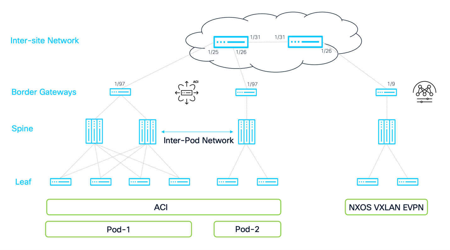
Note: This topology lacks production ready redundancy as it does not contain multiple spines and border gateways at each site/pod (nor redundant devices in the Inter-site Network). This was used to simplify the deployment steps for the purpose of this example and whitepaper.
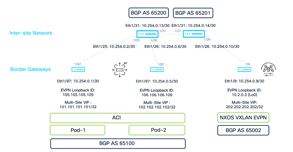
Infrastructure Configuration for Underlay and Overlay
Inter-site Network Configuration
To provide underlay connectivity for the two fabrics to communicate using VXLAN BGP EVPN, the ISN switches must provide a routed transport to carry the EVPN control plane and VXLAN data plane. To accommodate this, each ISN switch will have the BGP feature enabled, and will peer eBGP to both the ACI and NX-OS fabrics, as well as each other. This ensures that any IP address injected from each fabric will automatically be advertised to the remote fabric and allow IP reachability to be established.
1. Configure a dedicated VRF to forward the control and date plane traffic between sites: vxlan-infra. This is a recommendation but not a requirement. It helps isolate the underlay and overlay to a dedicated VRF to prevent overlaps with the default VRF. This VRF must be separate from the VRF used for the Inter-Pod network if the deployment is ACI Multi-Pod as well.
2. Configure the IP addresses and VRF onto the physical interfaces that connect the ISN switches to each fabrics border gateways, and each other.
3. Configure the BGP feature, and BGP neighbors between each fabrics border gateways, and each other using the appropriate Autonomous System Numbers.
CLI Configuration for ISN-1
vrf context vxlan-infra
interface Ethernet1/25
mtu 9216
vrf member vxlan-infra
ip address 10.254.0.2/30
no shutdown
interface Ethernet1/26
mtu 9216
vrf member vxlan-infra
ip address 10.254.0.6/30
no shutdown
interface Ethernet1/31
mtu 9216
vrf member vxlan-infra
ip address 10.254.0.13/30
no shutdown
feature bgp
router bgp 65200
vrf vxlan-infra
neighbor 10.254.0.1
remote-as 65100
address-family ipv4 unicast
neighbor 10.254.0.5
remote-as 65100
address-family ipv4 unicast
neighbor 10.254.0.14
remote-as 65201
address-family ipv4 unicast
BGP Session Verification for ISN-1
isn-1# show ip bgp neighbors 10.254.0.14 vrf vxlan-infra
BGP neighbor is 10.254.0.14, remote AS 65201, ebgp link, Peer index 5
BGP version 4, remote router ID 10.254.0.14
Neighbor previous state = OpenConfirm
BGP state = Established, up for 5w3d
Neighbor vrf: vxlan-infra
Peer is directly attached, interface Ethernet1/31
<SNIP>
isn-1# show bgp sessions vrf vxlan-infra
Total peers 3, established peers 1
ASN 65200
VRF vxlan-infra, local ASN 65200
peers 3, established peers 1, local router-id 10.254.0.2
State: I-Idle, A-Active, O-Open, E-Established, C-Closing, S-Shutdown
Neighbor ASN Flaps LastUpDn|LastRead|LastWrit St Port(L/R) Notif(S/R)
10.254.0.1 65100 4 00:00:14|never |never I 0/0 0/2
10.254.0.5 65100 4 00:00:14|never |never I 0/0 0/2
10.254.0.14 65201 0 10w5d |00:00:18|00:00:14 E 57312/179 0/0
vrf context vxlan-infra
interface Ethernet1/26
mtu 9216
vrf member vxlan-infra
ip address 10.254.0.10/30
no shutdown
interface Ethernet1/31
mtu 9216
vrf member vxlan-infra
ip address 10.254.0.14/30
no shutdown
feature bgp
router bgp 65201
vrf vxlan-infra
neighbor 10.254.0.9
remote-as 65002
address-family ipv4 unicast
neighbor 10.254.0.13
remote-as 65200
address-family ipv4 unicast
BGP Session Verification for ISN-2
isn-2# show ip bgp neighbors 10.254.0.13 vrf vxlan-infra
BGP neighbor is 10.254.0.13, remote AS 65200, ebgp link, Peer index 3
BGP version 4, remote router ID 10.254.0.2
Neighbor previous state = OpenConfirm
BGP state = Established, up for 5w3d
Neighbor vrf: vxlan-infra
Peer is directly attached, interface Ethernet1/31
<SNIP>
isn-2# show bgp sessions vrf vxlan-infra
Total peers 2, established peers 2
ASN 65201
VRF vxlan-infra, local ASN 65201
peers 2, established peers 2, local router-id 10.254.0.14
State: I-Idle, A-Active, O-Open, E-Established, C-Closing, S-Shutdown
Neighbor ASN Flaps LastUpDn|LastRead|LastWrit St Port(L/R) Notif(S/R)
10.254.0.9 65002 2 00:00:14|never |never I 0/0 0/2
10.254.0.13 65200 0 10w5d |00:00:05|00:00:55 E 179/57312 0/0
At this stage, BGP sessions between the two ISN switches have been established, but the sessions to the ACI border gateways in each pod, and the session to the NX-OS border gateway are still Idle because the remote configuration has not been completed. The following sections will illustrate how to deploy the border gateways at each fabric and validate the sessions are established.
Adding the ISN Switches to Nexus Dashboard
Since this example will illustrate how to interconnect an ACI fabric to an NX-OS fabric that is deployed and managed using Nexus Dashboard, having visibility into the ISN switches will allow Nexus Dashboard to easily retrieve the connected interfaces on the border gateway, and provide an easy workflow to deploy the IP addressing and BGP configuration shown in the section “NX-OS EVPN” Section.
Nexus Dashboard allows devices to be on-boarded in two modes:
● Managed Mode: In this mode, Nexus Dashboard will act as the single control point for all configuration and telemetry.
● Monitor Mode: In this mode, Nexus Dashboard will only learn the inventory of the on-boarded switches and allow that information to be used for other workflows and visibility.
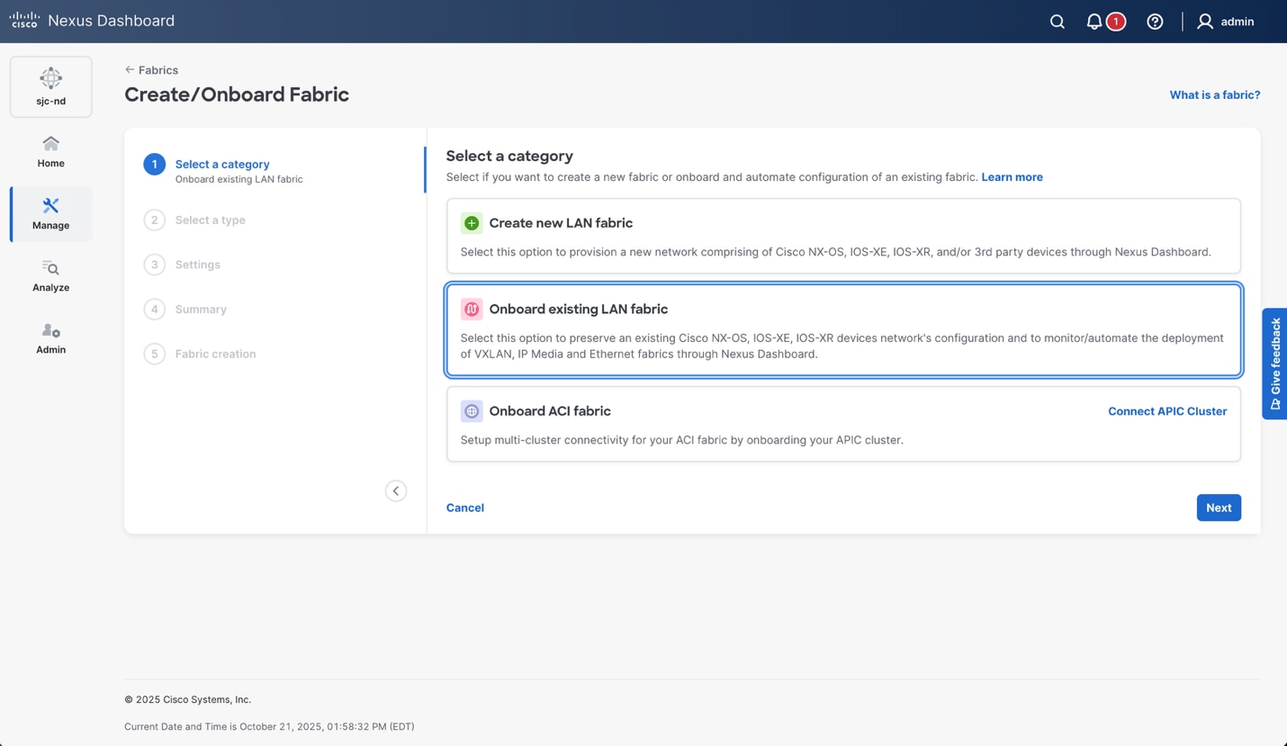
In this example, the ISN switches will be on-boarded to Nexus Dashboard in monitor mode. This was done to illustrate the manual configuration on each ISN device based on specific IP addressing in the topology, rather than having ND assign addresses from a pool. Alternatively, you could have ND manage these ISN switches and auto configure the links between the NX-OS ISN devices. To do this, log into Nexus Dashboard, and navigate to Manage > Fabrics > Action > Create fabric.
Choose “Onboard existing LAN fabric”.
The fabric type in this case is “External and Inter-fabric connectivity.” This allows Nexus Dashboard to build a logical and physical view of the remote ISN switches.
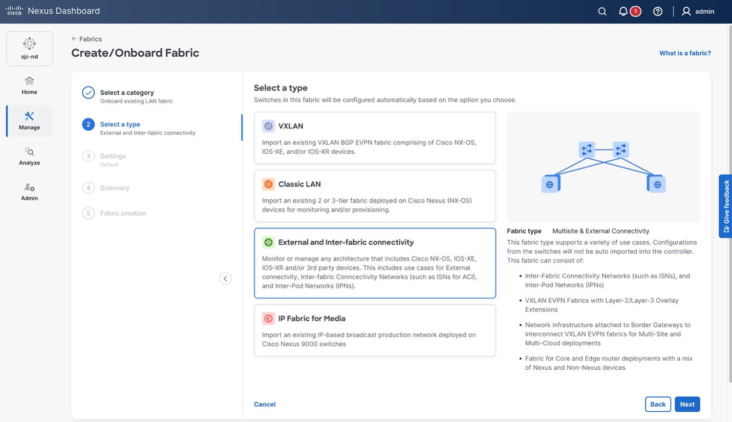
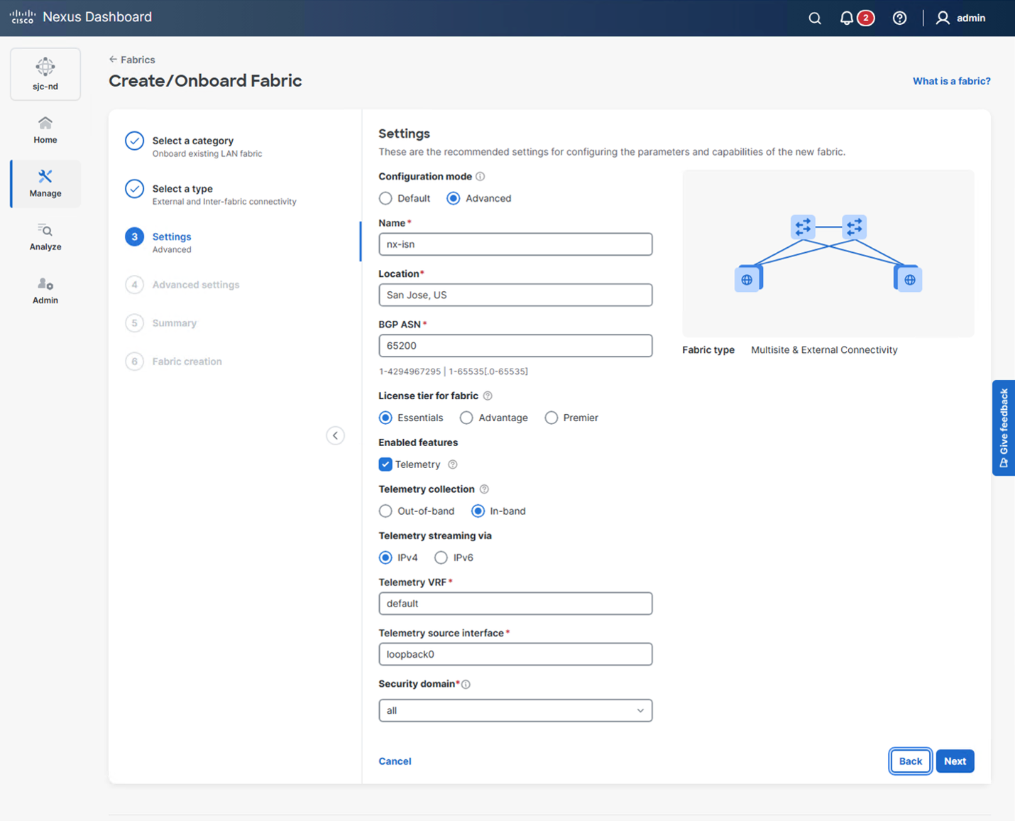
Click on “Advanced” in the “Configuration mode.” Give the fabric a name that represents the NX-OS ISN switches, enter a location, and BGP ASN. Since the NX-OS ISN switches are participating in an eBGP domain, they have different ASN numbers. In this case, use the first ASN number of ISN-1, and the configuration will be updated manually at a later step when the point-to-point connectivity is deployed for ISN-2 connecting to the NX-OS border gateway. Optionally, enable Telemetry.
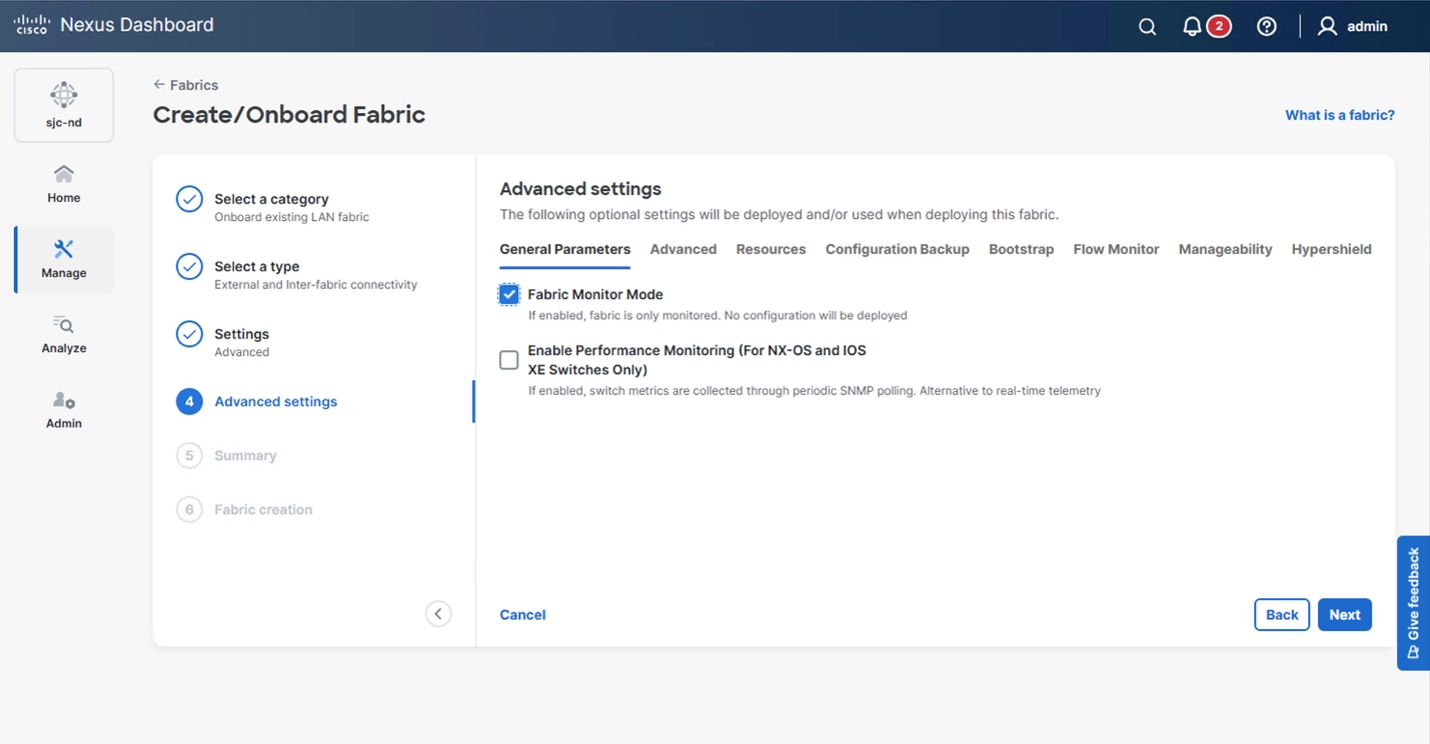
The next screen will give you advanced options, including the option to enable “Fabric Monitor Mode.” Click this, select Next, and then finish the fabric creation wizard.
After the fabric has been created, navigate to the fabric and add the ISN switches using Manage > Fabrics > nx-isn > Actions > Add switches.
Add the Seed IP (mgmt0 IP) for ISN-1, enter the authentication parameters, and set Max Hops to 1. This will allow Nexus Dashboard to automatically discover ISN-2 using LLDP/CDP. If there are additional devices, the Max Hops can be increased as needed.
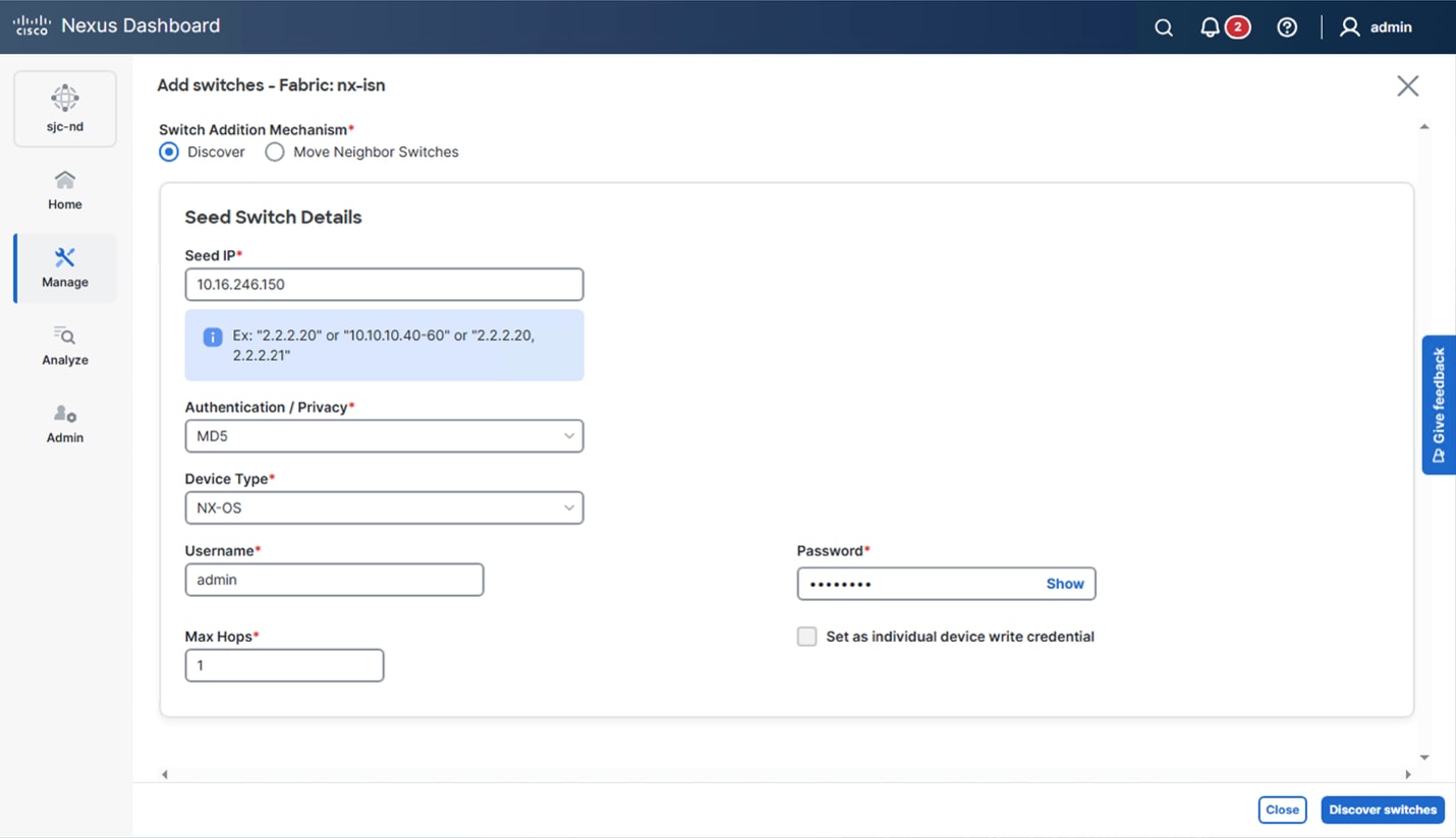
Select the ISN switches and choose Add switches.
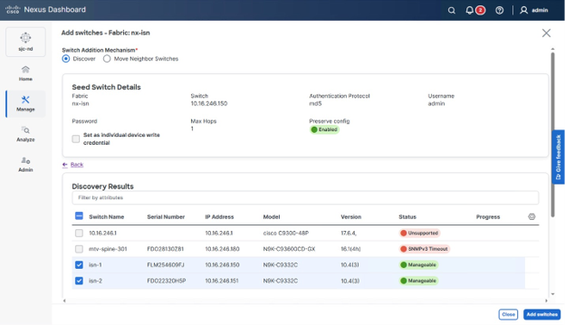
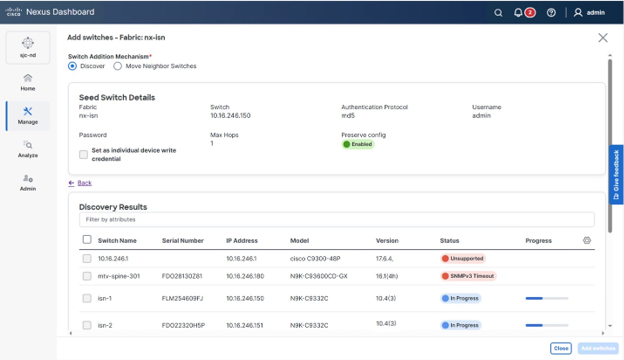
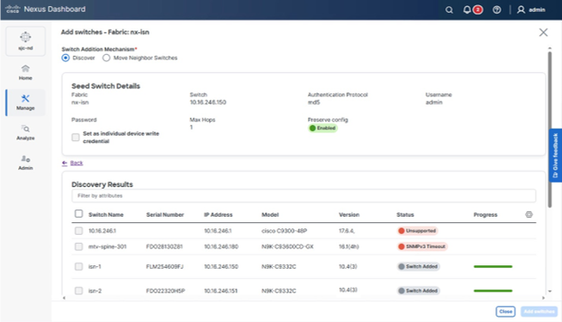
The switches will be processed and added to the fabric. Once complete, a green progress bar will signify they were successfully on-boarded.
The ACI 6.1(X) release introduces a new leaf role called “Border Gateway Leaf.” In the current release, this is a dedicated leaf for the VXLAN EVPN Border Gateway functionality. This leaf is commissioned the same way any other node in the fabric is commissioned, just with a dedicated role. In this example, leaf 501 in pod-1 and leaf 502 in pod-2 are commissioned with this role and will act as the border gateways.
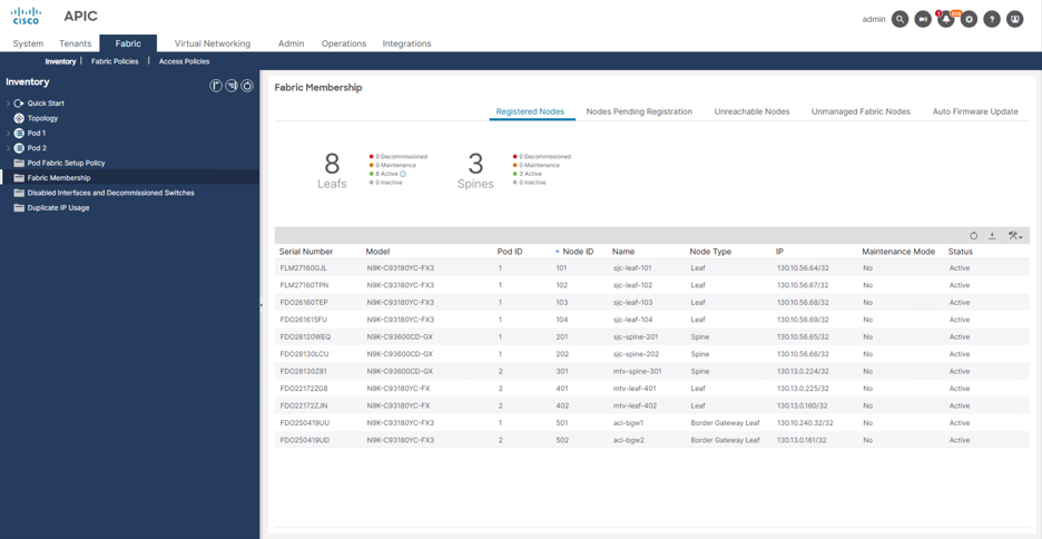
Once the border gateway leafs are registered and active, the underlay and overlay routing can be established. The APIC controller exposes the underlay and overlay VXLAN EVPN configuration through a “VXLAN Infra L3Out” construct within the “infra” tenant. There is a built-in wizard that will walk through the steps and required configuration options. This configuration will create the following:
● The underlay point-to-point connectivity between the border gateways and the ISN including the BGP neighbor configuration.
● The EVPN Control Plane Loopback for EVPN peering to the remote site.
● A VXLAN Border Gateway “set,” with each switches Multi-Site VIP. This is the external VIP address shared by all the border gateways in the same BGW-Set in the same pod.
● Remote VXLAN fabric(s), with their peer EVPN control plane IP and BGP AS.
Navigate to Tenants > infra > Networking > VXLAN Infra L3Outs, right click and select Create VXLAN Infra L3Out.
The wizard will ask for a name for the VXLAN Infra L3Out, provide a name and click Next.
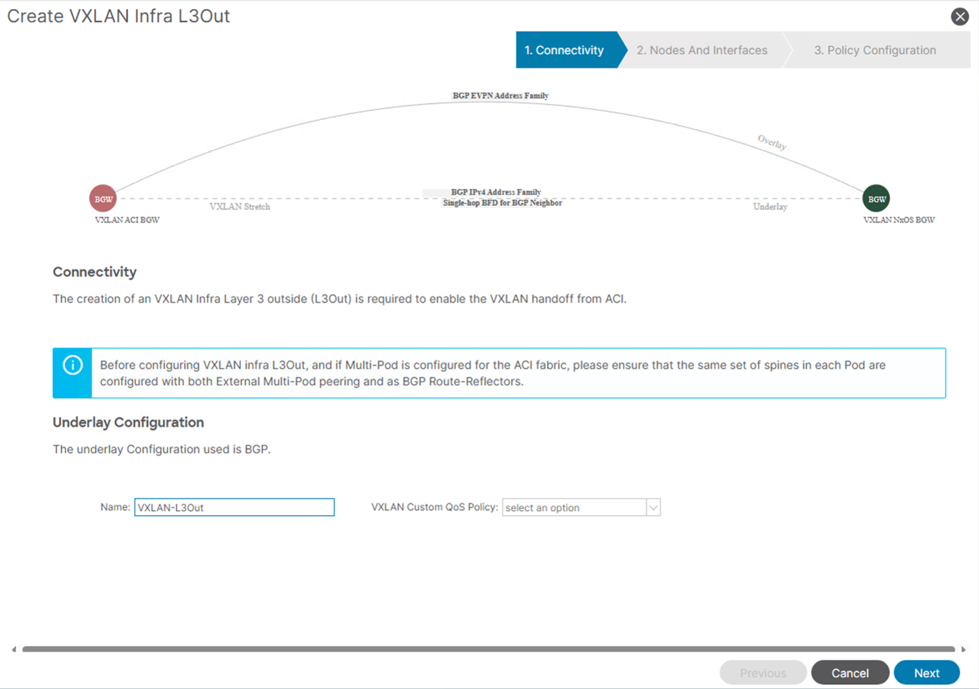
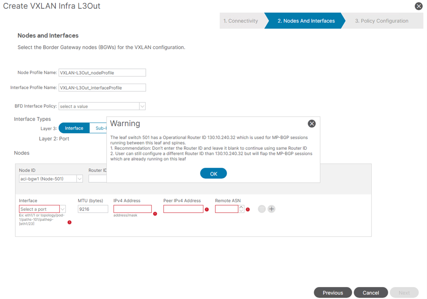
The next step will be to complete the configuration for the node and interfaces of the border gateways. By default, a suggested Node Profile Name and Interface Profile Name will be auto populated based on the name of the VXLAN Infra L3Out entered on the previous screen.
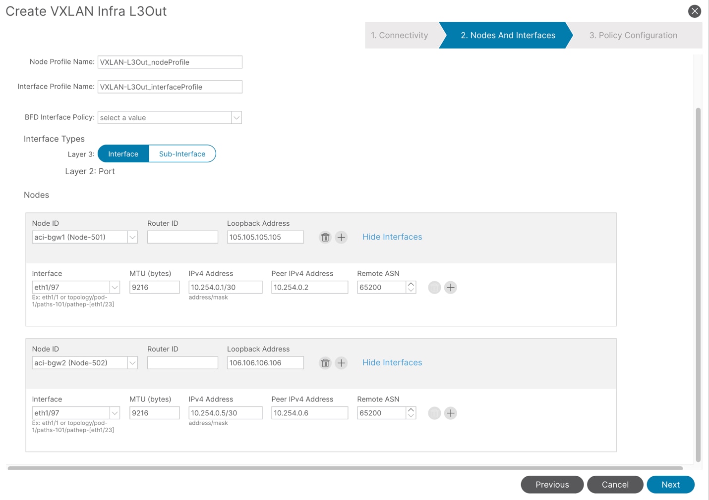
Choose the Interface type being used to connect and peer with the connected ISN switch(es). In this workflow, each border gateway in each pod will be configured. Select the first node. There will be a warning that is shown explaining that it is recommended to leave the “Router ID” field blank, as that router ID is used to establish the MP-BGP session between the ACI border gateway and the ACI spines. You can manually configure the Router ID, but the MP-BGP session to the spines will flap in this case. The use case for this is when the pod tep pool overlaps with the ISN devices or remote EVPN fabrics(s). By default, the Router ID will assume the IP address of the P-TEP on the ACI Border Gateway. If this is in use in the underlay routing or remote fabric, it will need be to different. But other than that, leave this field at default (blank).
Configure the EVPN loopback address in the Loopback Address field. This loopback will act as the source for the EVPN peering with the remote border gateways. Choose the physical interface that connects to the ISN Network, along with the IP address and peer ISN switches IP address and BGP ASN for the underlay routing. Repeat this step for all border gateways and click Next.
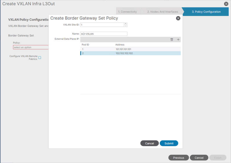
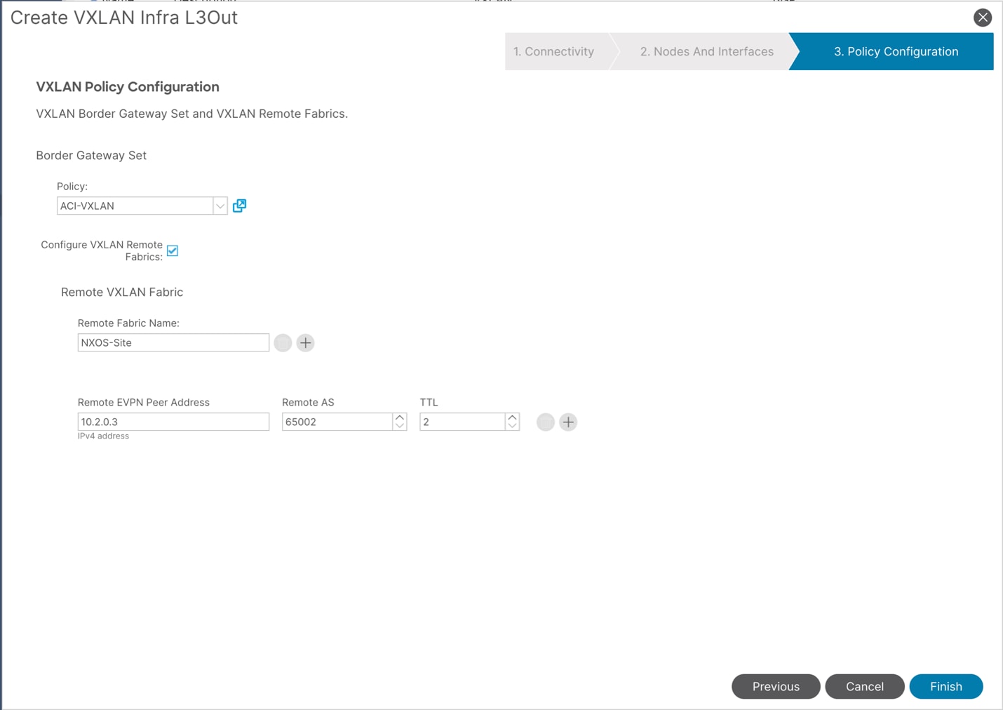
The next step is creating a “Border Gateway Set Policy.” This policy defines the VXLAN Site ID for the ACI site, along with the unique Multi-Site VIP shared by all the BGWs in the same pod. Enter a VXLAN Site ID, give the set a name, and then create the Multi-Site VIP addresses shared by all the BGWs in the same pod by defining the POD ID along with the desired Multi-Site VIP.
Next, you can click the check box next to “Configure VXLAN Remote Fabrics” to create the peer VXLAN EVPN configuration for the remote site. Give the site a name, specify the remote EVPN peer address for each remote site border gateway, enter a TTL that will accommodate enough physical eBGP hops between the ACI border gateways and the remote sites border gateways. In this example topology, there is only a single border gateway on the NX-OS site that will represent a single Remote EVPN Peer Address. By default, Nexus Dashboard will provision loopback0 with a unique IP address per device in the fabric for BGP peering. This IP address will be used to peer to ACI as well.
nx-bgw# show interface loopback 0
loopback0 is up
admin state is up,
Hardware: Loopback
Description: Routing loopback interface
Internet Address is 10.2.0.3/32
MTU 1500 bytes, BW 8000000 Kbit , DLY 5000 usec
reliability 255/255, txload 1/255, rxload 1/255
Encapsulation LOOPBACK, medium is broadcast
Auto-mdix is turned off
456882 packets input 28490775 bytes
0 multicast frames 0 compressed
0 input errors 0 frame 0 overrun 0 fifo
0 packets output 0 bytes 0 underruns
0 output errors 0 collisions 0 fifo
0 out_carrier_errors
Click Finish to push the configuration to the fabric and border gateways in each pod.
Control Plane MTU Considerations
Anytime a BGP neighbor is established, it is critical that the MTU being used at each end is matching and compatible. This ensures that as route updates occur, the BGP control plane packets being sent can be received un-truncated or fragmented, so the routing updates and session state can be stable. By default, ACI switches use MTU 9000 for any control plane update. This is dictated by the policy in System > System Settings > Control Plane MTU> Control Plane MTU Policy.
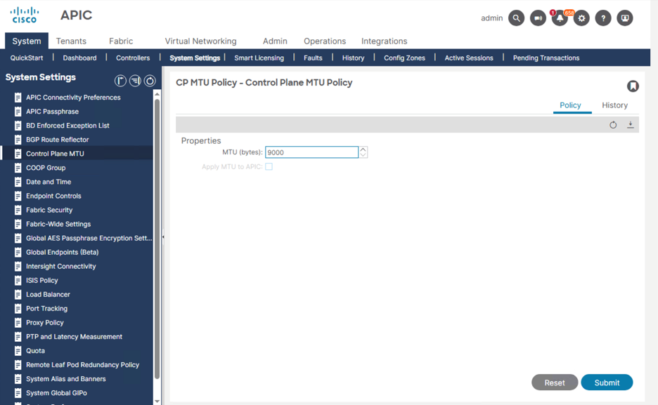
By default, the physical interfaces connecting to the ISN as well as loopback0 on the NX-OS border gateway(s) will have an MTU of 1500. This may also be true for the ISN devices depending on the platform and software used. Therefore, there are two options for ensuring MTU consistency for the BGP EVPN control plane between sites:
Lower the value of the Control Plane MTU Policy to 1500. When doing this, it is important to understand if this will create a conflict for any existing BGP neighbors that are set to use a higher MTU.
Increase the MTU of all devices/interfaces in the path for all NX-OS border gateways to at least 9000 to match the ACI fabric border gateways.
After the VXLAN Infra L3Out is deployed, we should establish BGP peering on both pods border gateways to ISN-1. This is to establish the underlay peering.
isn-1# show bgp sessions vrf vxlan-infra
Total peers 3, established peers 3
ASN 65200
VRF vxlan-infra, local ASN 65200
peers 3, established peers 3, local router-id 10.254.0.2
State: I-Idle, A-Active, O-Open, E-Established, C-Closing, S-Shutdown
Neighbor ASN Flaps LastUpDn|LastRead|LastWrit St Port(L/R) Notif(S/R)
10.254.0.1 65100 4 04:20:49|00:00:04|00:00:44 E 179/38939 0/2
10.254.0.5 65100 4 04:20:54|00:00:09|00:00:44 E 26568/179 0/2
10.254.0.14 65201 0 10w6d |00:00:01|00:00:03 E 57312/179 0/0
We should also see a BGP EVPN neighbor deployed on both pods border gateways pointing to the remote NX-OS border gateway loopback0 (10.2.0.3), however this will remain idle until the remote VXLAN Multi-Site configuration has been completed in the following sections. The BGP EVPN session should always be sourced from the dynamically allocated loopback with the “vxlan-evpn-rtep” role, driven from the Loopback Address defined in the VXLAN Infra L3out for the given border gateway. Because it is dynamically assigned, the loopback ID may be different across border gateways.
aci-bgw1# show bgp l2vpn evpn neighbors 10.2.0.3 vrf overlay-1
BGP neighbor is 10.2.0.3, remote AS 65002, ebgp link, Peer index 6, Peer Tag 0
BGP version 4, remote router ID 10.2.0.3
BGP state = Idle, up for 0w0d
Using Loopback3 as update source for this peer
External BGP peer might be upto to 2 hops away
<SNIP>
aci-bgw1# show ip interface loopback 3 vrf overlay-1
IP Interface Status for VRF "overlay-1"
lo3, Interface status: protocol-up/link-up/admin-up, iod: 118, mode: vxlan-evpn-rtep
IP address: 105.105.105.105, IP subnet: 105.105.105.105/32
IP broadcast address: 255.255.255.255
IP primary address route-preference: 0, tag: 0
aci-bgw2# show bgp l2vpn evpn neighbors 10.2.0.3 vrf overlay-1
BGP neighbor is 10.2.0.3, remote AS 65002, ebgp link, Peer index 4, Peer Tag 0
BGP version 4, remote router ID 10.2.0.3
BGP state = Idle, up for 0w0d
Using Loopback9 as update source for this peer
External BGP peer might be upto to 2 hops away
<SNIP>
aci-bgw2# show ip interface loopback 9 vrf overlay-1
IP Interface Status for VRF "overlay-1"
lo9, Interface status: protocol-up/link-up/admin-up, iod: 131, mode: vxlan-evpn-rtep
IP address: 106.106.106.106, IP subnet: 106.106.106.106/32
IP broadcast address: 255.255.255.255
IP primary address route-preference: 0, tag: 0
For the NX-OS EVPN fabric, we will leverage Nexus Dashboard to automate the underlay and overlay peering to build the EVPN connectivity to the ACI fabric. Below is a summary of the deployment steps with more details to follow throughout this section:
1. Ensure the fabric is built and there is a leaf switch defined with the role “Border Gateway.”
2. Onboard an External Fabric that will represent the ACI Fabric
3. Create a Multi-Site Domain/Fabric Group and add the ACI External Fabric and the NX-OS VXLAN EVPN Fabric to it as child fabrics
4. Create a Multi-Site Underlay link to peer eBGP to ISN-2 from the border gateway leaf.
5. Create two Multi-Site Overlay links, 1 for each ACI border gateway leaf to peer BGP EVPN from the NX-OS border gateway to the ACI border gateways.
6. Verify BGP connectivity is established.
In this example, there is a single switch on the NX-OS fabric with the role set to “Border Gateway.”
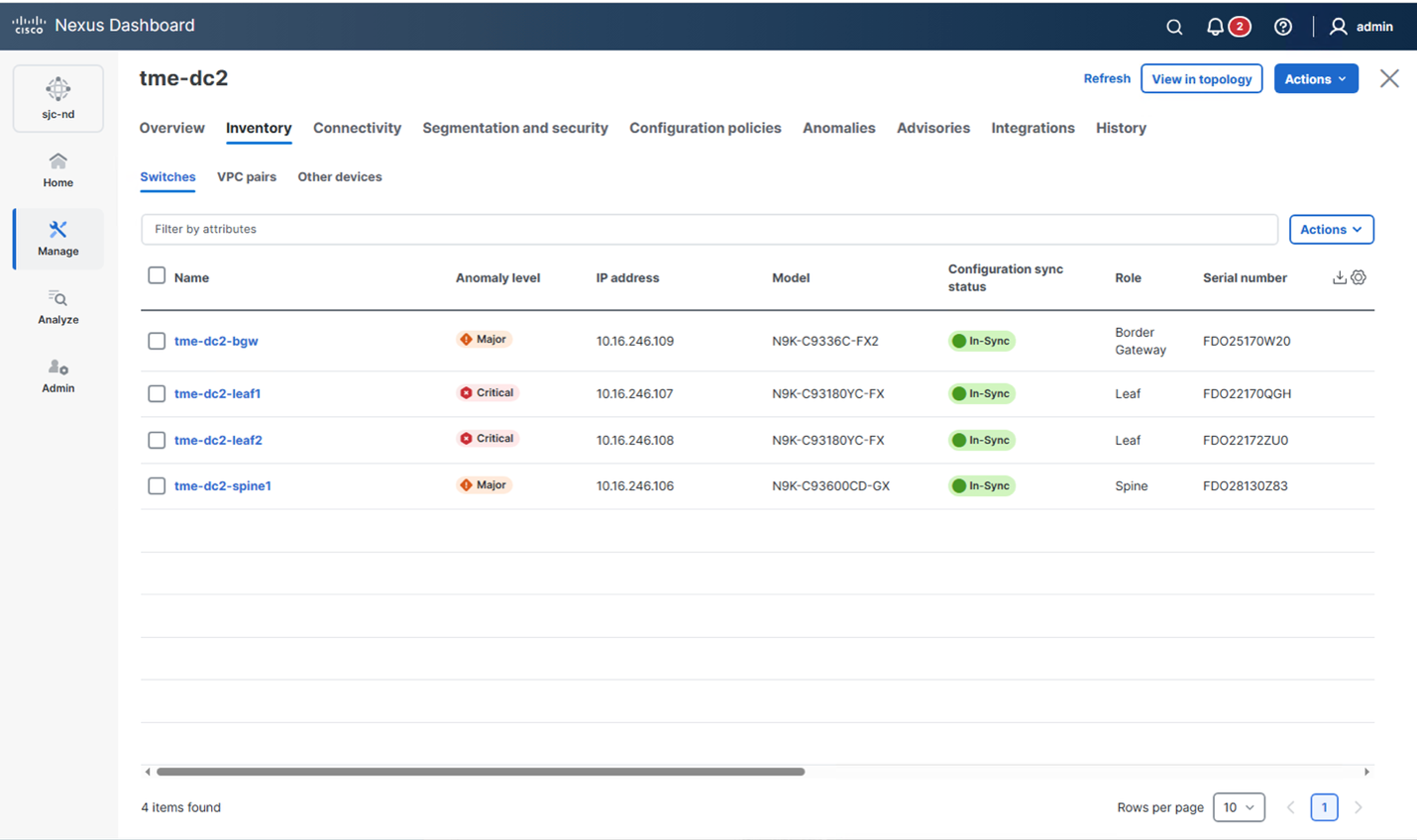
In the 4.1 release, Nexus Dashboard does not automate the ACI configuration for the Multi-Site BGW that was just performed on APIC directly. However, Nexus Dashboard can still build a representation of that fabric by adding it as an External Fabric. The benefit of doing this is that we can build a logical representation of the EVPN sessions, what links they are configured on, and to what ACI switches and loopbacks the session terminates. This is highlighted in the Figures below. First, a new fabric is created and “Onboard existing LAN fabric” is selected.
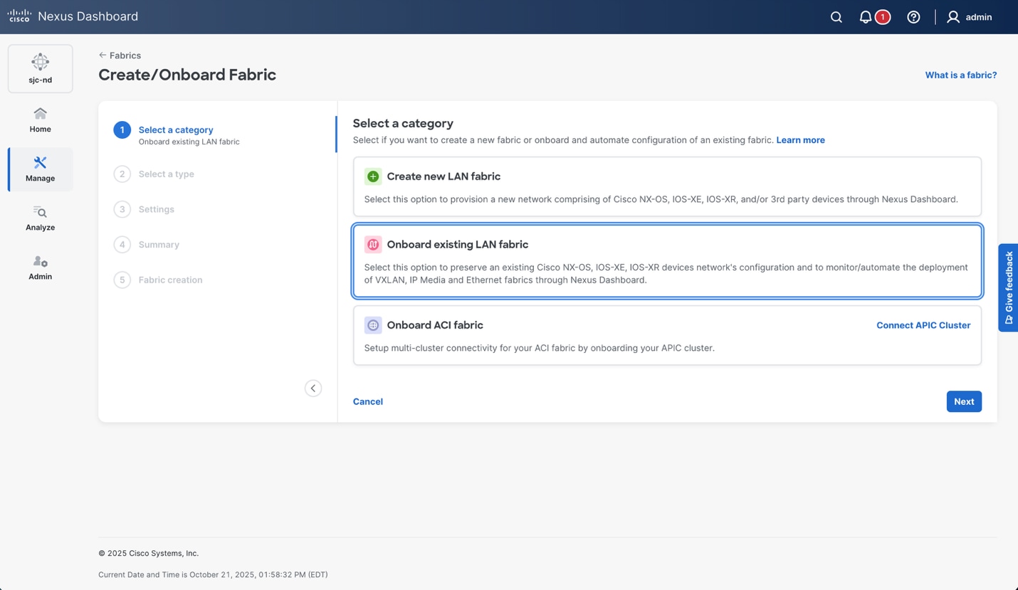
The fabric type in this case is “External and Inter-fabric connectivity.” This allows Nexus Dashboard to build a logical and physical view of the remote fabric.
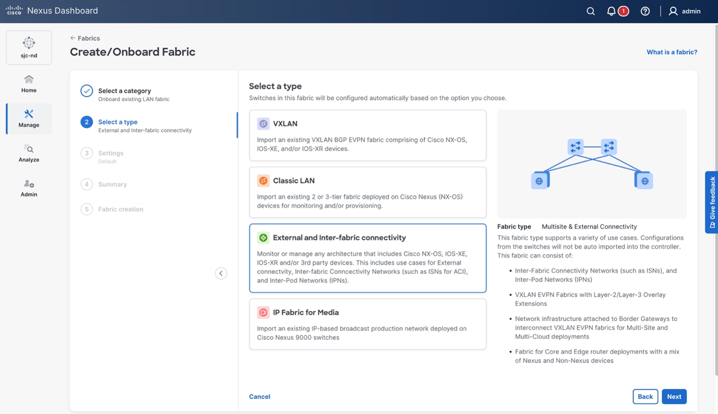
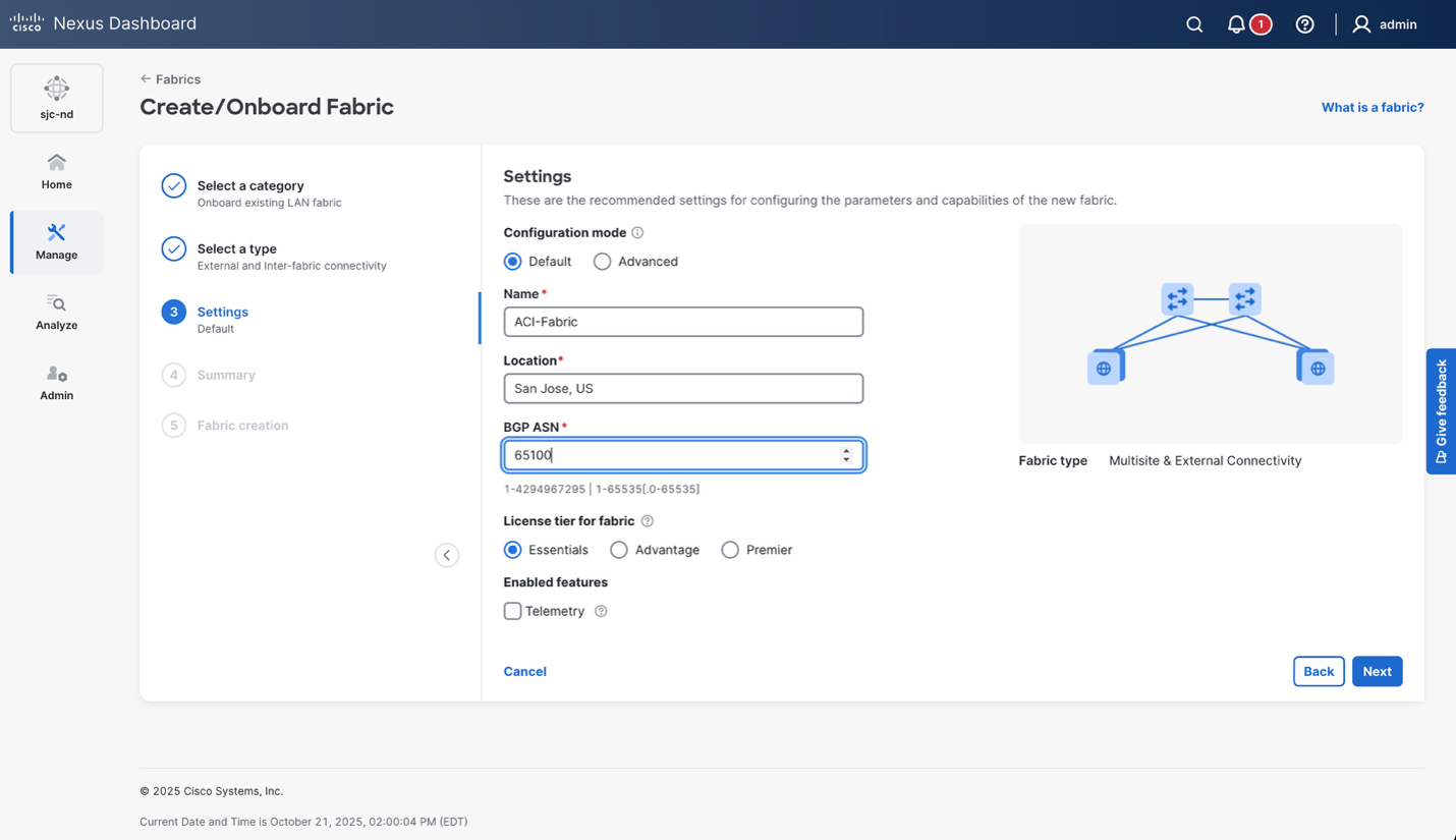
Information about the fabric can be entered, and the BGP AS number of the ACI fabric should be entered. This BGP AS number is the AS deployed within the BGP Route Reflector configuration by default. Or if the source AS number was modified in the VXLAN Infra L3Out configuration, it would be that one. This AS will be used under the neighbor BGP EVPN configuration on the NX-OS border gateway(s).
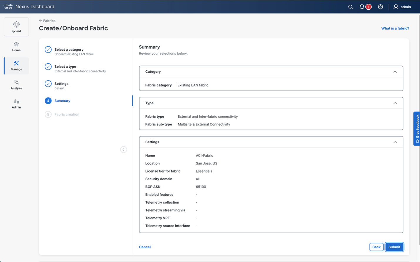
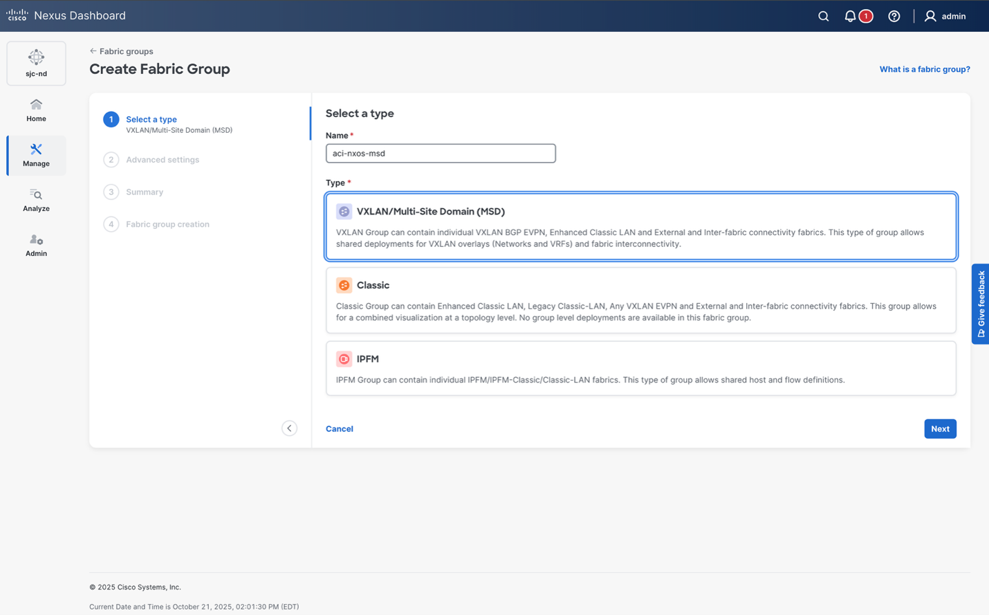
Nexus Dashboard leverages Fabric Groups, or “Multi-Site Domains (MSD)” to automate the configuration for multi-site deployments. An MSD allows users to specify underlay and overlay connectivity profiles, deploy VRFs and networks across sites, and manage GPO and global policies from a single place. An MSD is created in this case to build the Multi-site topology between ACI and NX-OS.
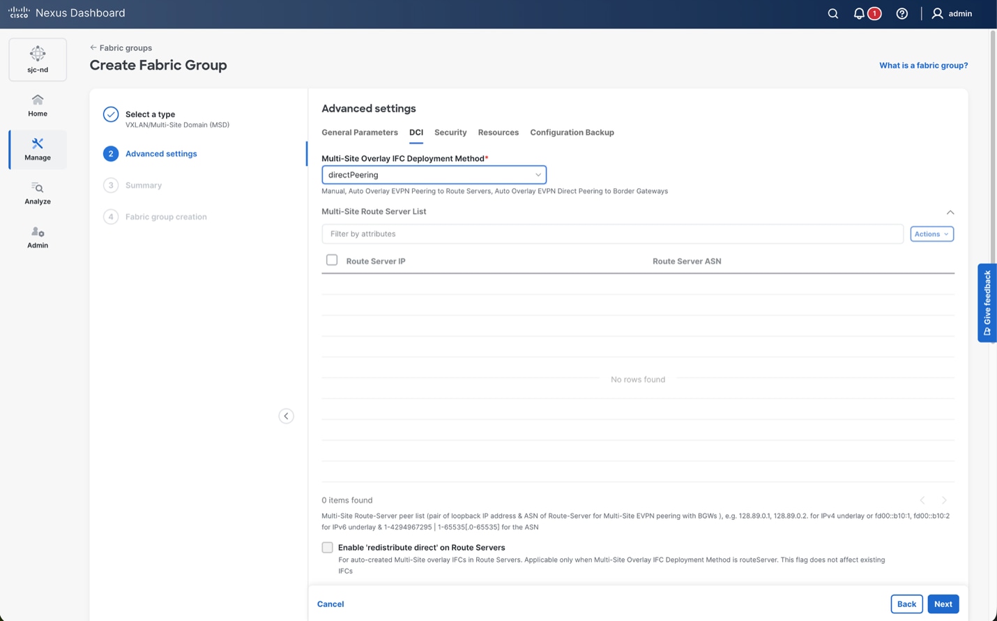
An MSD provides a few different peering options for the fabrics, including Route Server and Direct Mode. As of the ACI 6.1(5)M release, the supported mode is “directPeering” so that is selected under the Advanced Settings > DCI> Multi-Site Overlay IFC Deployment Method”. Support for Route-Server has been added in the ACI 6.2(2)F release, and information can be found by reviewing the “ACI Border gateway route server” in the Layer3 Networking Configuration Guide for release 6.2(X).
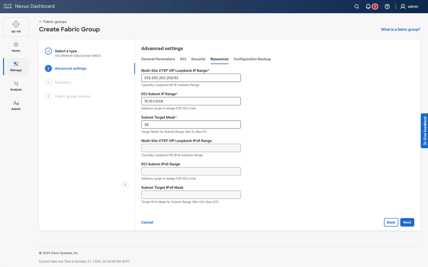
Furthermore, the Multi-Site Data Plane VIP used in this example was manually allocated to 202.202.202.202/32. By default, Nexus Dashboard will give you a pool of IP addresses to allocate to each border gateway set at each site. Considering in this example we wanted to manually allocate the IP address, this configuration is set manually under Advanced Settings > Resources > Multi-Site VTEP VIP Loopback IP Range.
Note: If the intended design includes multiple NX-OS fabrics as part of the Fabric Group/Multi-Site Domain, it is better to utilize a non /32 Loopback IP Range so that multiple /32 addresses can be allocated uniquely for each site. In this example, the VIP is manually configured to illustrate how this field is allocated to the switch, and to provide consistency in the topology.
The DCI Subnet IP Range can be left at defaults. Considering this example uses the 10.254.0.X subnet range for DCI links across ACI and NX-OS for peering with the ISN switches, the IP addressing will be manually configured using the Links workflow in the next section. You could allow Nexus Dashboard to automate the IP addressing for these links using this field.
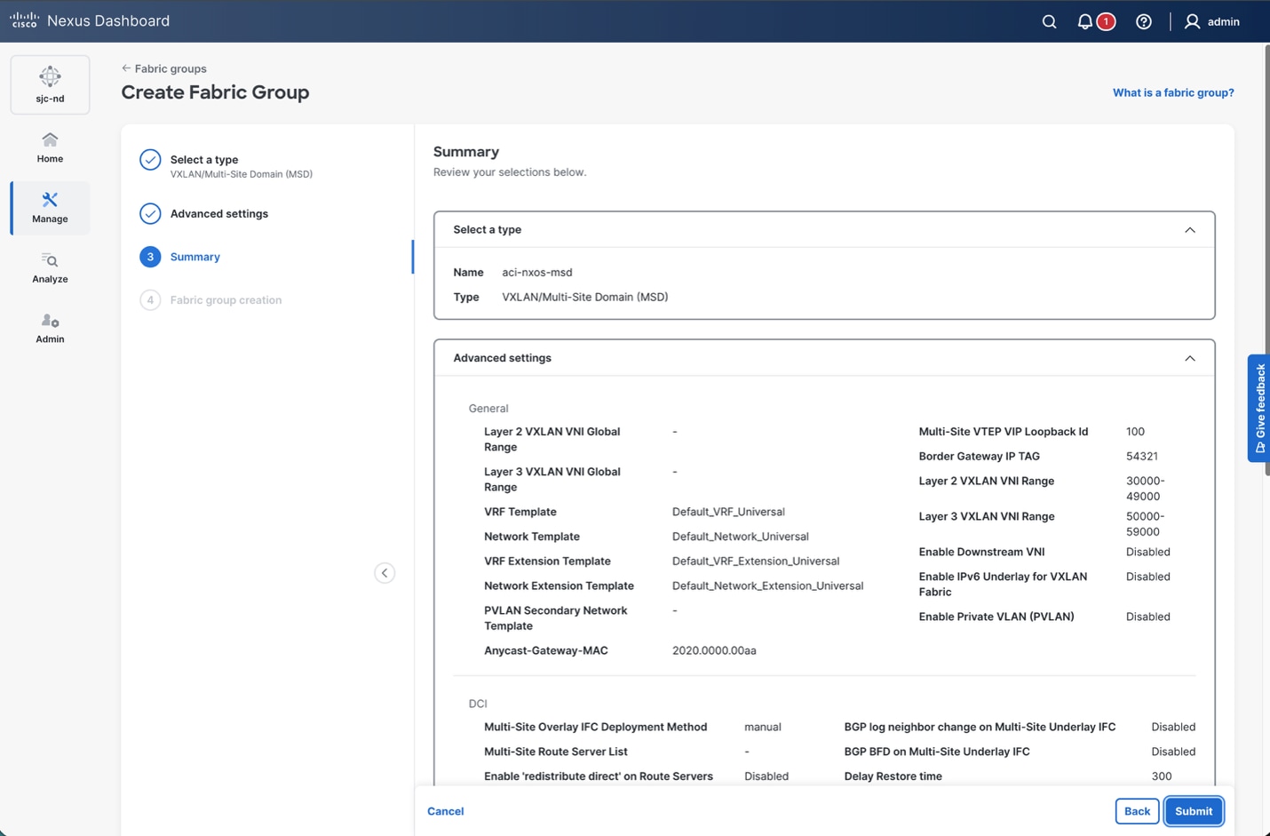
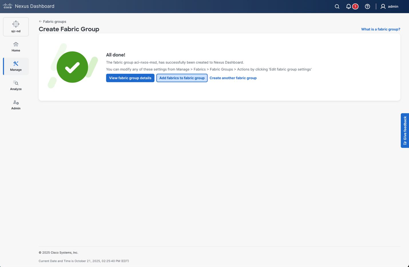
Despite Nexus Dashboard not having control of the configuration from APIC, in order for the ND to provision the NX-OS fabric configuration for BGW Multi-Site to the External Fabric representing ACI, both NX-OS and the External Fabric must be added to the same MSD/Fabric Group. When navigating to the MSD, the Action > Add Child Fabric button will provide a list of available fabrics to be added to the MSD. This is also why the ACI fabric was manually added as an external fabric, so that it would become available to be added as a child fabric within the MSD.
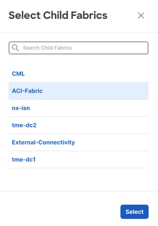
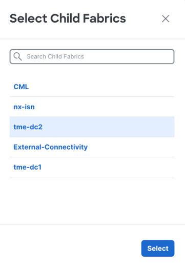
After the ACI and NX-OS fabric has been added to the MSD, the next step is to build the underlay point-to-point connection to the ISN (ISN-2 in this example), and also the overlay BGP EVPN sessions to each ACI border gateway in each pod. This is done using the Connectivity > Links functionality exposed in the MSD. Create a link for the underlay point-to-point connection.
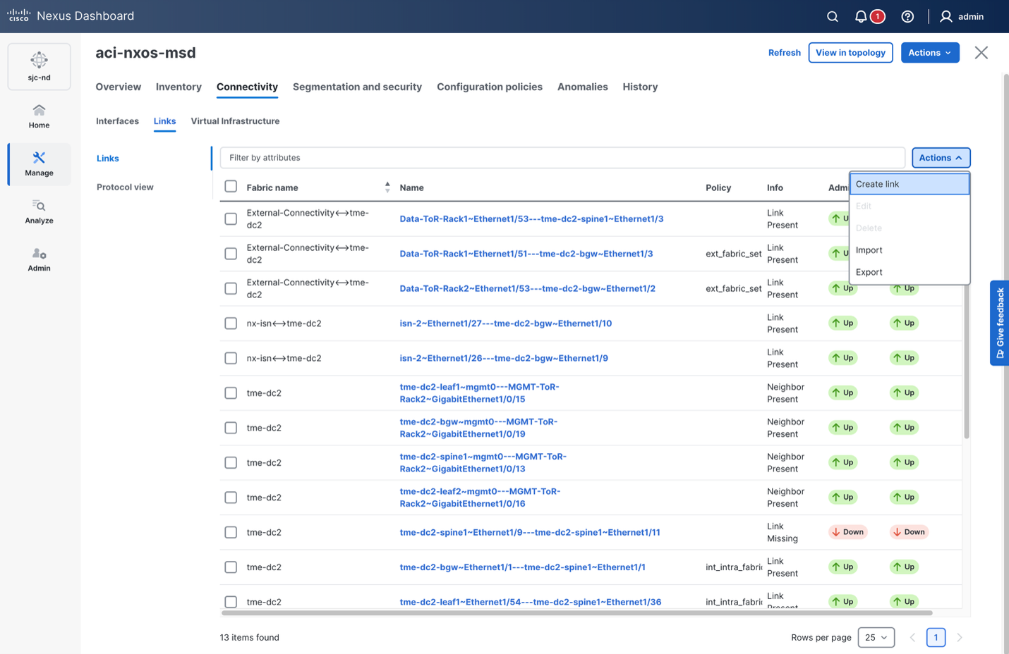
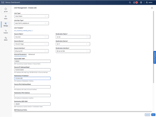
The Link-Sub-Type in this case would be “MULTISITE_UNDERLAY”, and the Link Template should be changed to “ext_multisite_underlay_setup”.
Note: In the ND 4.2 release, this has been changed to “Policy” and “Multi-Site Underlay” respectively.
The information for the source and destination fabric, device, and interface should be assigned as this will determine on which interface the IP addressing will be assigned.
Note: The ISN switches are also on-boarded to the Nexus Dashboard cluster as an External Fabric in “Monitor Mode”. Having the switches added as an external fabric allows Nexus Dashboard to learn all the physical connectivity via LLDP, and build links for them that can be used in this workflow.
The Source and Destination BGP AS numbers will determine how the BGP neighbor configuration will get created using the destination IP address.
Note: If PTP is enabled in the fabric, ensure that the “Inherit ttag/ttag-strip” knob remains selected (it is by default). This ensure that the TTag (Timestamp Tag) applied within the NX-OS fabric with PTP is removed before being sent to the remote ACI fabric. The ACI fabric uses a different implementation of TTag and the frames will be dropped when tagged by NX-OS.

Once the underlay point-to-point link is created, it’s time to create the overlay BGP EVPN peering between the NX-OS border gateway(s) and the ACI border gateways in each pod. This requires creating additional links in the Fabric > Connectiviy > Links page. The Link-Sub-Type in this case would be “MULTISITE_OVERLAY”, and the Link Template should be changed to “ext_evpn_multisite_overlay_setup”.
Note: In the ND 4.2 release, this has been changed to “Policy” and “Multi-Site Overlay” respectively.
Unlike the previous underlay link, where physical connectivty between the NX-OS border gateway and ISN-2 is established, this link will create the logical configuration for the BGP EVPN peering. The ACI fabric that is added to the MSD is really a placeholder fabric to fulfill the requirement for a “Destination Fabric”, and because of that, manual configuration for the “Destination Device” and “Destination Interface” will need to be entered and created. This is simply meta data, and the name of the device and interface do not need to be exactly the same as what you have inventoried in APIC. Once text is typed into these field, the option to “Create” will appear and can be clicked.
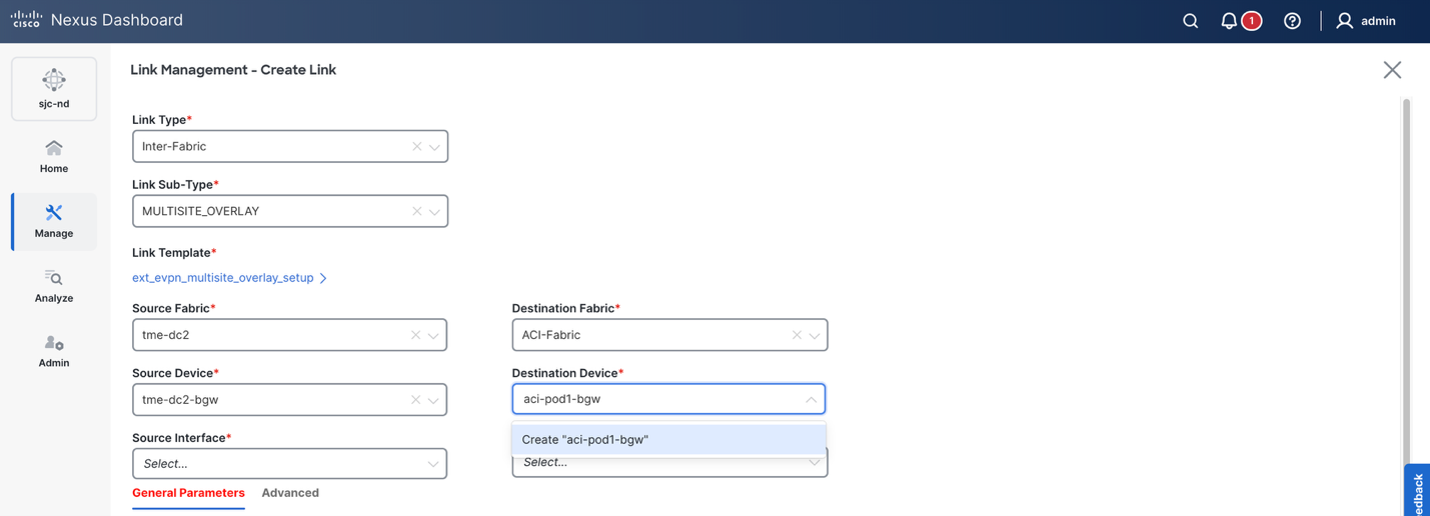
This needs to be done for both the Destination Device and Destination Interface. Considering the goal is to establish a BGP EVPN session to each border gateway in each pod on the ACI fabric, and the ACI fabric is also using a loopback (105.105.105.105 on pod1-bgw and 106.106.106.106 on pod2-bgw), the naming scheme below is used.
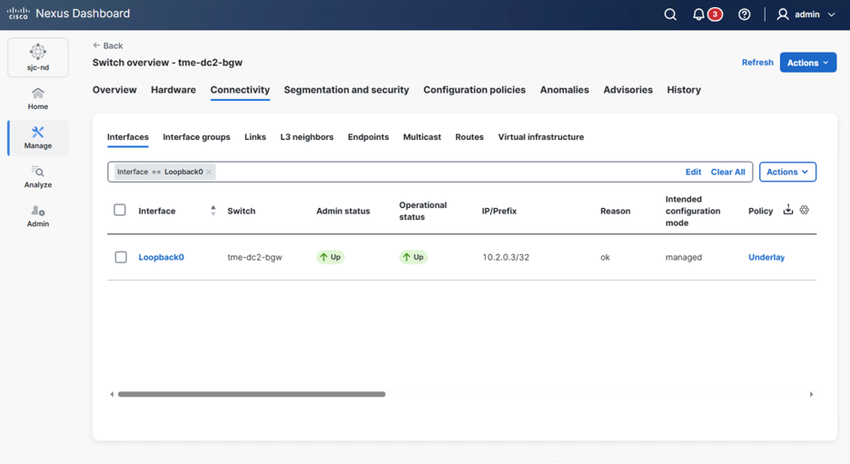
Ensure that the Source BGP ASN is correct, and that the Source IP Address is the IP address allocated to the NX-OS BGW. By default, this is the loopback0 configuration on the border gateway, which can be validated with below CLI and screenshot below:
nx-bgw#show ip interface brief
IP Interface Status for VRF "default"(1)
Interface IP Address Interface Status
Lo0 10.2.0.3 protocol-up/link-up/admin-up <---
Lo1 10.3.0.3 protocol-up/link-up/admin-up
Lo100 202.202.202.202 protocol-up/link-up/admin-up
Eth1/1 10.4.0.1 protocol-up/link-up/admin-up
Eth1/2 10.32.0.6 protocol-up/link-up/admin-up
Eth1/3 10.32.0.2 protocol-up/link-up/admin-up
Eth1/9 10.254.0.9 protocol-up/link-up/admin-up
The destination IP address should be the BGP EVPN Loopback for the specific ACI border gateway, as well as the BGP AS number should match that on the ACI side.
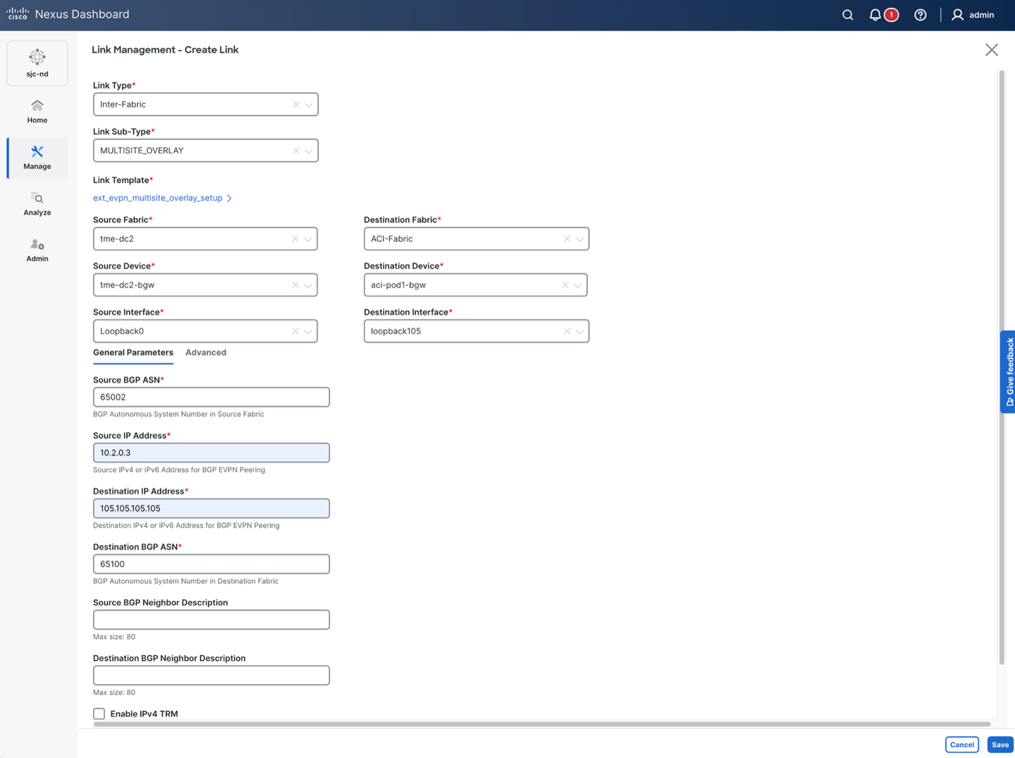
Repeat the same steps for the border gateway in pod-2 with EVPN IP 106.106.106.106. In a production scenario, you will have multiple border gateways each with unique loopback0 IP addresses acting as the EVPN neighbor source. You’ll create the same configuration to each ACI border gateway with the other NX-OS border gateways too.
At this stage, when we do a “Recalculate and Deploy” at the MSD level by clicking the Actions > Recalculate and Deploy on the MSD, the BGW on the NX-OS fabric should get the underlay and overlay configuration to build the connectivity to the ISN and ACI fabric:
evpn multisite border-gateway 65002
delay-restore time 300
interface nve1
multisite border-gateway interface loopback100
interface loopback100
ip address 202.202.202.202/32 tag 54321
ip pim sparse-mode
ip router ospf UNDERLAY area 0.0.0.0
no shutdown
interface ethernet1/9
no switchport
ip address 10.254.0.9/30 tag 54321
evpn multisite dci-tracking
ttag
ttag-strip
mtu 9216
no shutdown
interface ethernet1/1
no switchport
ip address 10.4.0.1/30
evpn multisite fabric-tracking
description connected-to-tme-dc2-spine1-Ethernet1/1
ip ospf network point-to-point
ip pim sparse-mode
ip router ospf UNDERLAY area 0.0.0.0
mtu 9216
no shutdown
ptp
router bgp 65002
neighbor 10.254.0.10
remote-as 65201
update-source Ethernet1/9
address-family ipv4 unicast
next-hop-self
exit
exit
neighbor 105.105.105.105
remote-as 65100
update-source loopback0
ebgp-multihop 5
peer-type fabric-external
address-family l2vpn evpn
send-community both
rewrite-evpn-rt-asn
exit
exit
neighbor 106.106.106.106
remote-as 65100
update-source loopback0
ebgp-multihop 5
peer-type fabric-external
address-family l2vpn evpn
send-community both
rewrite-evpn-rt-asn
Now that the NX-OS configuration is deployed, the EVPN peer on the ACI border gateways that was previously Idle should move to Established. The same state should be viewable on the NX-OS border gateway as well.
aci-bgw1# show bgp l2vpn evpn neighbors 10.2.0.3 vrf overlay-1
BGP neighbor is 10.2.0.3, remote AS 65002, ebgp link, Peer index 6, Peer Tag 0
BGP version 4, remote router ID 10.2.0.3
BGP state = Established, up for 4d14h
Using loopback3 as update source for this peer
External BGP peer might be upto 2 hops away
aci-bgw2# show bgp l2vpn evpn neighbors 10.2.0.3 vrf overlay-1
BGP neighbor is 10.2.0.3, remote AS 65002, ebgp link, Peer index 4, Peer Tag 0
BGP version 4, remote router ID 10.2.0.3
BGP state = Established, up for 4d14h
Using loopback9 as update source for this peer
External BGP peer might be upto 2 hops away
nx-bgw# show bgp l2vpn evpn neighbors 105.105.105.105
BGP neighbor is 105.105.105.105, remote AS 65100, ebgp link, Peer index 7
BGP version 4, remote router ID 130.10.240.32
Neighbor previous state = OpenConfirm
BGP state = Established, up for 4d14h
Neighbor vrf: default
Using loopback0 as update source for this peer
Using iod 10 (loopback0) as update source
External BGP peer might be up to 5 hops away
Nx-bgw# show bgp l2vpn evpn neighbors 106.106.106.106
BGP neighbor is 106.106.106.106, remote AS 65100, ebgp link, Peer index 8
BGP version 4, remote router ID 130.13.0.161
Neighbor previous state = OpenConfirm
BGP state = Established, up for 4d14h
Neighbor vrf: default
Using loopback0 as update source for this peer
Using iod 10 (loopback0) as update source
External BGP peer might be up to 5 hops away
When looking at the ISN switches, all IP addressing that will be used should be learned via BGP from their respective fabrics, indicating that the control plane is fully established, and data plane reachability to the Data Plane TEP addresses should be okay.
isn-1# show ip route vrf vxlan-infra
IP Route Table for VRF "vxlan-infra"
'*' denotes best ucast next-hop
'**' denotes best mcast next-hop
'[x/y]' denotes [preference/metric]
'%<string>' in via output denotes VRF <string>
10.2.0.0/22, ubest/mbest: 1/0
*via 10.254.0.14, [20/0], 6w6d, bgp-65200, external, tag 65201
10.2.0.3/32, ubest/mbest: 1/0 <-- NX-OS Border Gateway EVPN Loopback
*via 10.254.0.14, [20/0], 6w6d, bgp-65200, external, tag 65201
10.3.0.3/32, ubest/mbest: 1/0
*via 10.254.0.14, [20/0], 6w6d, bgp-65200, external, tag 65201
10.5.0.0/22, ubest/mbest: 1/0
*via 10.254.0.14, [20/0], 3w4d, bgp-65200, external, tag 65201
10.16.1.0/24, ubest/mbest: 1/0
*via 10.254.0.14, [20/0], 6w6d, bgp-65200, external, tag 65201
10.254.0.0/30, ubest/mbest: 1/0, attached <-- ACI Pod-1 Border Gateway Underlay Subnet
*via 10.254.0.2, Eth1/25, [0/0], 04:44:43, direct
10.254.0.2/32, ubest/mbest: 1/0, attached
*via 10.254.0.2, Eth1/25, [0/0], 04:44:43, local
10.254.0.4/30, ubest/mbest: 1/0, attached <-- ACI Pod-2 Border Gateway Underlay Subnet
*via 10.254.0.6, Eth1/26, [0/0], 04:44:46, direct
10.254.0.6/32, ubest/mbest: 1/0, attached
*via 10.254.0.6, Eth1/26, [0/0], 04:44:46, local
10.254.0.8/30, ubest/mbest: 1/0 <-- NX-OS Border Gateway Underlay Subnet
*via 10.254.0.14, [20/0], 6w6d, bgp-65200, external, tag 65201
10.254.0.12/30, ubest/mbest: 1/0, attached
*via 10.254.0.13, Eth1/31, [0/0], 10w6d, direct
10.254.0.13/32, ubest/mbest: 1/0, attached
*via 10.254.0.13, Eth1/31, [0/0], 10w6d, local
101.101.101.101/32, ubest/mbest: 1/0 <-- ACI Pod-1 Border Gateway Data-Plane TEP
*via 10.254.0.1, [20/0], 04:09:38, bgp-65200, external, tag 65100
102.102.102.102/32, ubest/mbest: 1/0 <-- ACI Pod-2 Border Gateway Data-Plane TEP
*via 10.254.0.5, [20/0], 04:09:42, bgp-65200, external, tag 65100
105.105.105.105/32, ubest/mbest: 1/0 <-- ACI Pod-1 Border Gateway EVPN Loopback
*via 10.254.0.1, [20/0], 04:44:37, bgp-65200, external, tag 65100
106.106.106.106/32, ubest/mbest: 1/0 <-- ACI Pod-2 Border Gateway EVPN Loopback
*via 10.254.0.5, [20/0], 04:44:42, bgp-65200, external, tag 65100
202.202.202.202/32, ubest/mbest: 1/0 <-- NX-OS Border Gateway Data-Plane TEP
*via 10.254.0.14, [20/0], 6w6d, bgp-65200, external, tag 65201
Overlay Networking and Use Cases
With the underlay routing and overlay EVPN connectivity between sites established, the next logical step is to deploy the overlay networking to allow application and client connectivity in various scenarios. This section will highlight the configuration options within APIC and Nexus Dashboard to allow this. The following scenarios will be covered:
1. Stretch Layer-2 networks
2. Stretch Layer-3 networks
3. External prefix advertisement from ACI to NX-OS
4. External prefix advertisement from NX-OS to ACI
5. Transit routing between external prefixes across ACI and NX-OS
6. End-To-End Policy awareness
For examples 1-5, ACI will be the only policy aware site, as the NX-OS fabric will not be leveraging security groups. This will highlight the ACI specific configuration required to allow communication and enforce policy. For example, 6, NX-OS will be security group enabled and policy will be applied at both sites for end-to-end policy awareness.
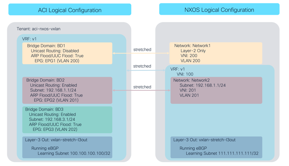
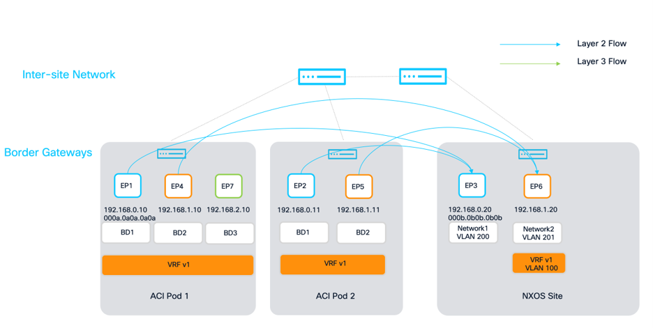
The below figure highlights the initial logical configuration that is deployed at each site. The ACI configuration has already been pre-configured, however the NX-OS configuration will be deployed in the respective section using Nexus Dashboard. The key points are that the VRF, along with BD1/Network1 and BD2/Network2 are stretched. BD3/Network3 is local to ACI, and each site has a layer3 out where unique prefixes are being learned.
The fundamentals of any network include Layer-2 switching or bridging. Within ACI, we create a Tenant (if not already created), VRF (if not already created), Endpoint Group, and Bridge Domain to allow Layer-2 learning and forwarding within a given VLAN. The EPG is then extended to Virtual or Physical workloads leveraging a VLAN ID to attract traffic from hosts. Within Nexus Dashboard and NX-OS VXLAN EVPN, we create a Network that maps a Layer-2 VNI to a VLAN. That VLAN is then trunked on switches and ports to attract VLANs from hosts. If we wanted to take the two architectures, and marry them together, we would need to define the following:
1. Network level configuration as explained above.
2. VXLAN Stretch configuration that will map the VNI of the Network in NX-OS to the VNI of the Bridge Domain in ACI.
3. Policy that defines the classification of a network to an endpoint security group based on the Layer-2 VNI.
The end goal of this section will be to have two networks deployed across both sites where end hosts in those networks can talk to the other hosts in the same network. One of them will be L2 Only, and the other will have a gateway address configured to allow routing to other networks for the Layer-2 example afterwards.
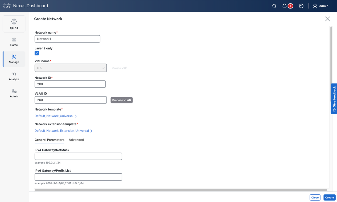
Beginning with the Network Deployment on Nexus Dashboard, a new Network can easily be created by navigating to the Fabric Group/MSD > Segmentation and Security > Networks > Actions > Create. If you want the network to be purely layer-2, check “Layer 2 only”. In this example, this is selected to demonstrate a pure L2 network.
If the network should be routable, you can assign the appropriate VRF and an anycast gateway address to the network.
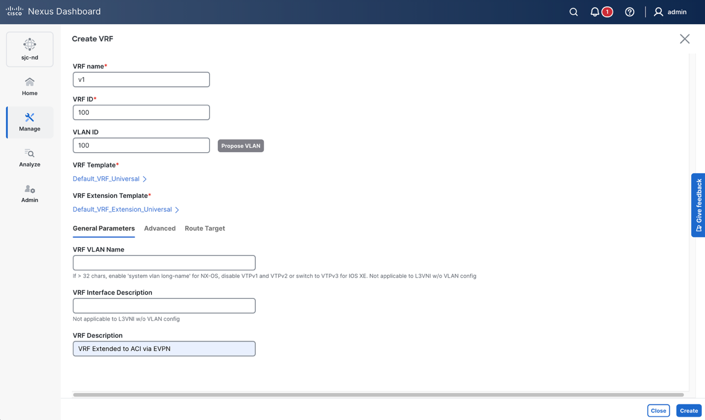
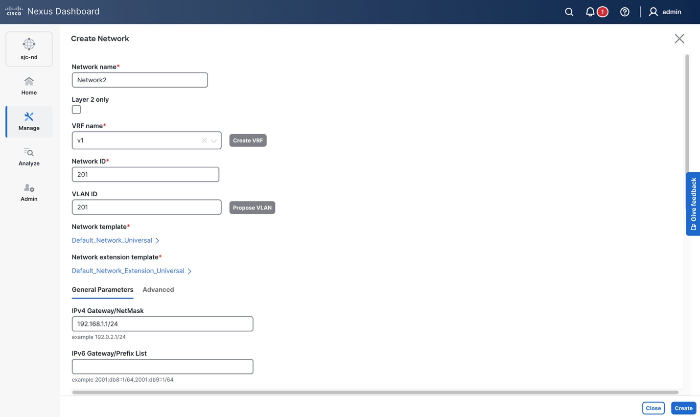
Note the Network ID (VNI’s) that were used in this example to match the VRF to VNI 100, Network1 (Layer-2 only) to VNI 200, and Network2 to VNI 201. These can be any unused values in any current or new deployment and are reference examples for this whitepaper and deployment. Once the networks are created, they can be attached to switches and ports using the Multi-Attach workflow under the Actions menu in the Networks view. It is important to note that the network is attached to the border gateway even if there are no hosts attached, as the network attachment allows the stretching of VRF’s and networks to and from the remote site.
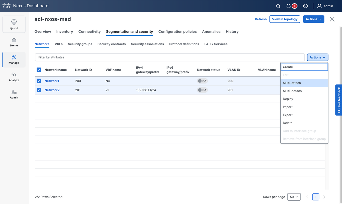
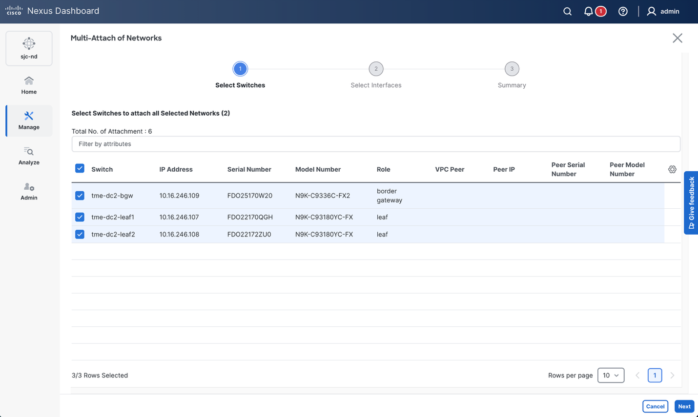
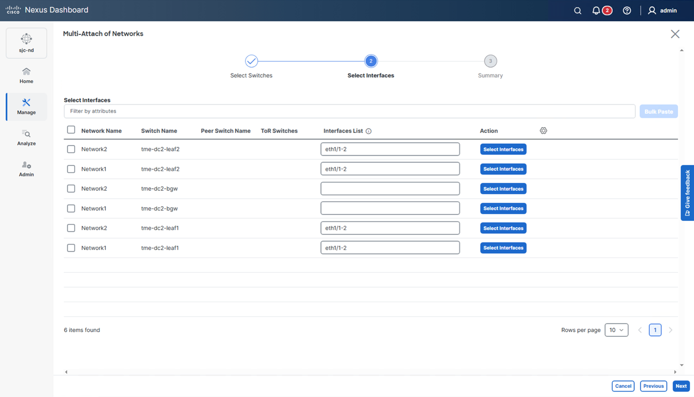
At this stage, when we “Proceed to full switch deploy”, or do a “Recalculate and Deploy” at the MSD level by clicking the Actions > Recalculate and Deploy on the MSD, the border gateway and leaf switches should get the required networking configuration as part of the VXLAN EVPN fabric domain. The “Deploy All” button will deploy the configuration to the leafs and border gateway, and the “Pending Config” can be reviewed.
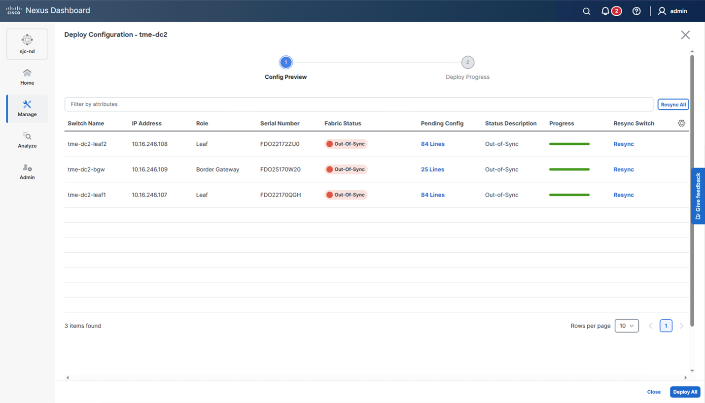
The example configuration that is generated for each device is below:
Border gateway:
vlan 200
vn-segment 200
vlan 201
vn-segment 201
interface nve1
member vni 201
multisite ingress-replication
mcast-group 239.1.1.0
member vni 200
multisite ingress-replication
mcast-group 239.1.1.0
evpn
vni 200 l2
rd auto
route-target import auto
route-target export auto
vni 201 l2
rd auto
route-target import auto
route-target export auto
Leafs 1 and 2:
interface ethernet1/1
switchport
switchport mode trunk
ttag
ttag-strip
mtu 9216
spanning-tree port type edge trunk
no shutdown
switchport trunk allowed vlan 200-201
interface ethernet1/2
switchport
switchport mode trunk
ttag
ttag-strip
mtu 9216
spanning-tree port type edge trunk
no shutdown
switchport trunk allowed vlan 200-201
vlan 100
vn-segment 100
vrf context v1
vni 100
rd auto
address-family ipv4 unicast
route-target both auto
route-target both auto evpn
address-family ipv6 unicast
route-target both auto
route-target both auto evpn
exit
interface Vlan100
vrf member v1
ip forward
ipv6 address use-link-local-only
no ip redirects
no ipv6 redirects
mtu 9216
no shutdown
router bgp 65002
vrf v1
address-family ipv4 unicast
advertise l2vpn evpn
redistribute direct route-map fabric-rmap-redist-subnet
maximum-paths ibgp 2
exit
address-family ipv6 unicast
advertise l2vpn evpn
redistribute direct route-map fabric-rmap-redist-subnet
maximum-paths ibgp 2
interface nve1
member vni 100 associate-vrf
member vni 201
mcast-group 239.1.1.0
member vni 200
mcast-group 239.1.1.0
vlan 200
vn-segment 200
vlan 201
vn-segment 201
interface Vlan201
vrf member v1
ip address 192.168.1.1/24 tag 12345
fabric forwarding mode anycast-gateway
no shutdown
evpn
vni 200 l2
rd auto
route-target import auto
route-target export auto
vni 201 l2
rd auto
route-target import auto
route-target export auto
Note: TTAG configuration is also included here because the fabric settings have PTP enabled. TTag configuration can be ignored for fabrics without PTP being enabled.
Now that the NX-OS configuration has been pushed by Nexus Dashboard, the APIC configuration can be completed to allow VNI translation and policy. There is an assumption that the reader of this paper is familiar with how to create Tenants, VRFs, EPGs, and Bridge Domains in ACI, so that part is omitted, but the matching configuration for the two new NX-OS networks has been defined.
The first new piece of configuration that is introduced is the “VXLAN Stretch” object. These objects operate at the VRF and Bridge Domain level and provide a way to stretch them to remote VXLAN sites via a BGW set along with the VNI mapping (normalization). Stretched VRFs and BDs are advertised to EVPN peers specified in the BGW set with the normalized VNI. Navigate to Tenants > Tenant X > Networking > VXLAN Stretch, right click, and create a new one for the VRF. In this case, we will choose the VRF (v1 in this example which was pre-configured) and the border gateway set that was created during the VXLAN Infra L3Out creation wizard. The “Normalized VNI” field provides an input for the external VRF that we should map to this ACI VRF. We used VNI 100 for the VRF on NX-OS, so that is mapped here.
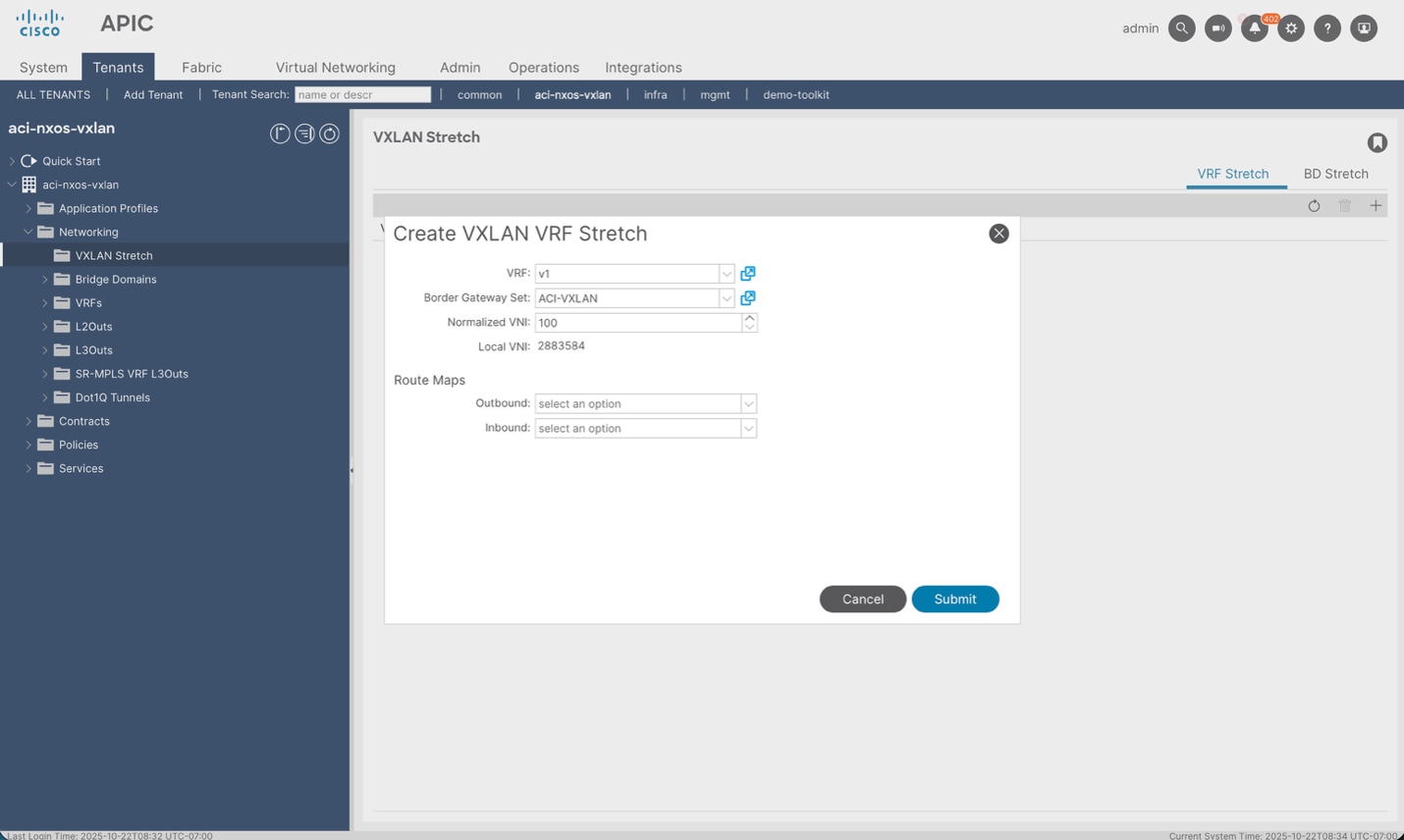
Continue the VXLAN stretch configuration for the other two networks. One important thing to note is that for any ACI Bridge Domain that is stretched via VXLAN EVPN, that Bridge Domain must be set to L2 Unknown Unicast Flood and ARP Flooding must also be enabled. This is required because the external network may include silent hosts that we are unable to resolve without flooding. If the Bridge Domain you are trying to create a VXLAN Stretch object for does not have this configuration, you will be asked to enable it.
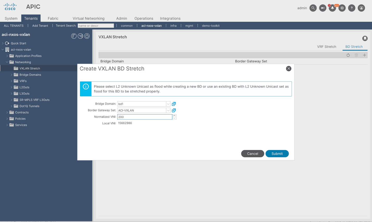
Create the VXLAN Stretch configuration for Network VNI 200 and Network VNI 201 mapping to their respective Bridge Domains and border gateway sets.
The final step is to classify remote endpoints/prefixes to a security group so that policy can be mapped as one cohesive domain where traffic is implicitly allowed. The Nexus One, and ACI Border Gateway features leverages ESGs to do this. Create an ESG if one is not already created under Tenants > Tenant X > Application Profiles > Application Profile X > Endpoint Security Groups. The first step requires defining a VRF (v1 in this case) to match on.
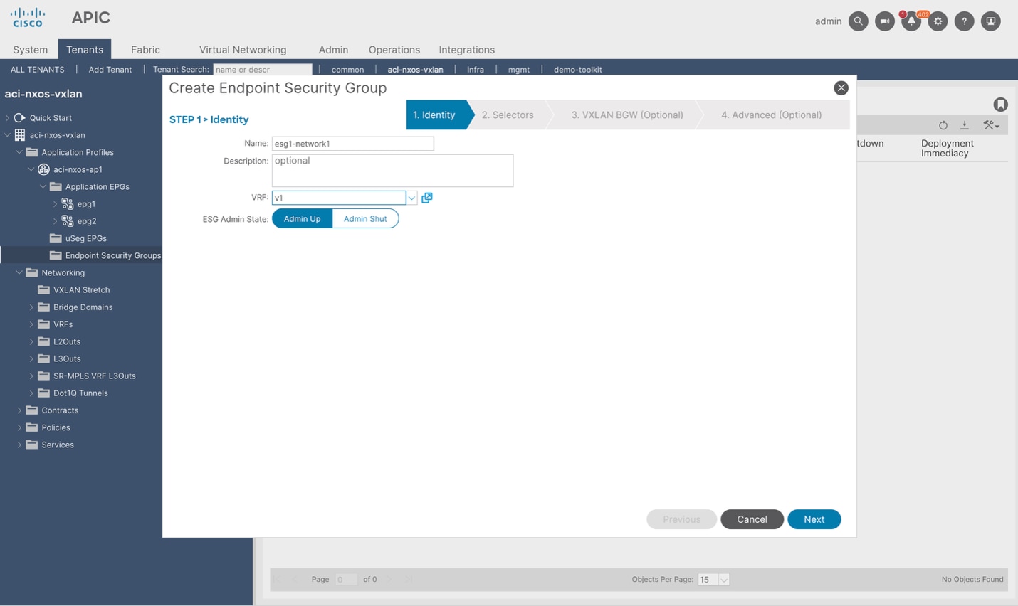
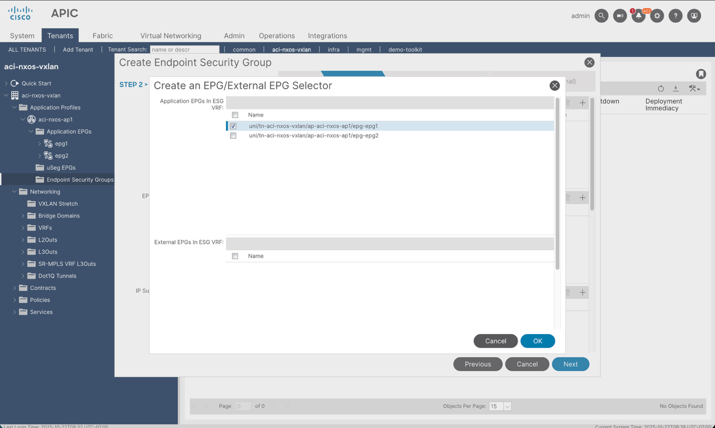
After this, there will be a list of other match conditions that we can leverage to classify the traffic into the ESG. One of them is the “EPG/External EPG Selector.” This will provide a list of all the EPGs in the Application Profile and VRF. In this case we are creating the Layer-2 communication policy for the first network, so the EPG where that network is defined is selected. This is required to classify all the endpoints connected in the ACI domain to the stretched network into the defined ESG.
Next, we can leverage the “VXLAN BD Selector” to also match against any MAC address of an externally learned endpoint that is part of the VXLAN Stretch configuration for a given bridge domain. This ensures that Endpoints are learned in the NX-OS fabric, and traffic is sent from the NX-OS fabric towards ACI, any endpoints with VNI 200 (Layer-2) will automatically be mapped to this ESG and thus communication will be allowed to all other endpoints within the first EPG1. This is also needed because the remote EVPN fabric is not policy aware in this example. For the case where the remote EVPN fabric is policy aware, it would be sending type-2 routes with a pcTag on which we could match.
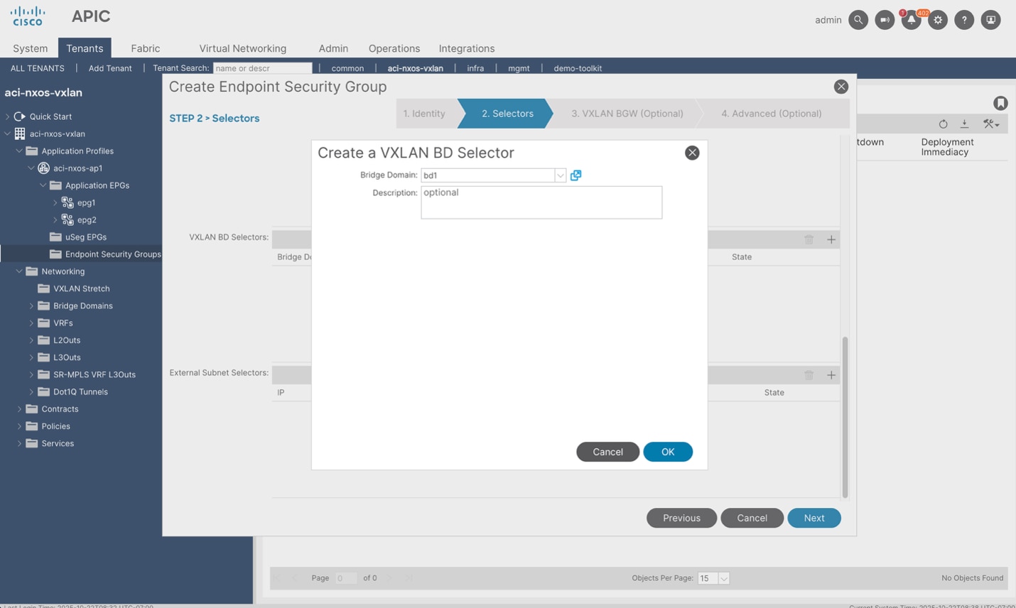
Finally, APIC also allows you to map a normalized Security Group Tag (SGT) to an ESG in case BGP EVPN routes from the remote sites contain the SGT mapping. In this example, this capability is not used because only the ACI site is policy aware and the remote sites do not add the SGT mapping in the EVPN routes. This field will be utilized in final example where end-to-end policy awareness is deployed.
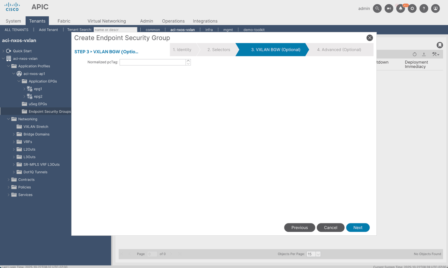
Repeat the same steps for the 2nd Network.
After the config is deployed, connectivity between the intra-subnet endpoints in BD1/Network1 and BD2/Network2 should be established. For verification purposes, we can check the BGP control plane to see if the remote L2 entries (Network1) and L2/L3 entries (Network2) are learned on each border gateway.
ACI Border Gateway (Both Pods):
aci-bgw1# show bgp l2vpn evpn 000b.0b0b.0b0b vrf overlay-1
Route Distinguisher: 65002:200 <-- IMPORTED FROM NX-OS BGW
BGP routing table entry for [2]:[0]:[0]:[48]:[000b.0b0b.0b0b]:[0]:[0.0.0.0]/216, version 1039 dest ptr 0x9c32a4ae
Paths: (1 available, best #1)
Flags: (0x0000000000000202 0000000000) on xmit-list, is not in rib/evpn, is not in HW, is locked
Multipath: eBGP iBGP
Advertised path-id 1
Path type (0x909e0660): external 0x40000028 0x4002000 ref 1 adv path ref 1, path is valid, is best path
Imported to 1 destination(s)
AS-Path: 65002 , path sourced external to AS
202.202.202.202 (metric 0) from 10.2.0.3 (10.2.0.3)
Origin IGP, MED 2000, localpref 100, weight 0 tag 4294966000, propagate 0, floating svi 0, tunnel resolved 0
Received label 200
Extcommunity:
RT:65100:200
SOO:65100:1291845613
COST:pre-bestpath:170:1610612736
ENCAP:8
0x310:03100000:0000fdea
Route Distinguisher: 1:32440202 (L2VNI 15662986) <-- LOCALLY ORIGINATED
BGP routing table entry for [2]:[0]:[0]:[48]:[000b.0b0b.0b0b]:[0]:[0.0.0.0]/216, version 1042 dest ptr 0x9c3292e8
Paths: (1 available, best #1)
Flags: (0x0000000000000212 0000000000) on xmit-list, is in rib/evpn, is not in HW
Multipath: eBGP iBGP
Advertised path-id 1
Path type (0x90dd03ec): external 0xc0000028 0x400 ref 0 adv path ref 1, path is valid, is best path, in rib
Imported from (0x909e0660) 65002:200:[2]:[0]:[0]:[48]:[000b.0b0b.0b0b]:[0]:[0.0.0.0]/112
AS-Path: 65002 , path sourced external to AS
202.202.202.202 (metric 0) from 10.2.0.3 (10.2.0.3)
Origin IGP, MED 2000, localpref 100, weight 0 tag 4294966000, propagate 0, floating svi 0, tunnel resolved 0
Received label 200
Extcommunity:
RT:65100:200
SOO:65100:1291845613
COST:pre-bestpath:170:1610612736
ENCAP:8
0x310:03100000:0000fdea
Path-id 1 advertised to peers:
130.10.56.65 130.10.56.66 <-- ADVERTISED TO SPINES
aci-bgw1# show bgp l2vpn evpn 192.168.1.20 vrf overlay-1
Route Distinguisher: 65002:201
BGP routing table entry for [2]:[0]:[0]:[48]:[0050.569c.c370]:[32]:[192.168.1.20]/272, version 1036 dest ptr 0x9c329aba
Paths: (1 available, best #1)
Flags: (0x0000000000000202 0000000000) on xmit-list, is not in rib/evpn, is not in HW, is locked
Multipath: eBGP iBGP
Advertised path-id 1
Path type (0x909e03f0): external 0x40000028 0x4002000 ref 2 adv path ref 1, path is valid, is best path, remote nh not installed
Imported to 2 destination(s)
AS-Path: 65002 , path sourced external to AS
202.202.202.202 (metric 0) from 10.2.0.3 (10.2.0.3)
Origin IGP, MED 2000, localpref 100, weight 0 tag 4294966000, propagate 0, floating svi 0, tunnel resolved 0
Received label 201 100
Extcommunity:
RT:65100:100
RT:65100:201
SOO:65100:1291845613
COST:pre-bestpath:170:1610612736
ENCAP:8
0x310:03100000:0000fdea
Router MAC:0200.caca.caca
Path-id 1 not advertised to any peer
Route Distinguisher: 1:31719393 (L2VNI 14942177)
BGP routing table entry for [2]:[0]:[0]:[48]:[0050.569c.c370]:[32]:[192.168.1.20]/272, version 1037 dest ptr 0x9c32a786
Paths: (1 available, best #1)
Flags: (0x0000000000000212 0000000000) on xmit-list, is in rib/evpn, is not in HW
Multipath: eBGP iBGP
Advertised path-id 1
Path type (0x90dd04c4): external 0xc0000028 0x400 ref 0 adv path ref 1, path is valid, is best path, remote nh not installed, in rib
Imported from (0x909e03f0) 65002:201:[2]:[0]:[0]:[48]:[0050.569c.c370]:[32]:[192.168.1.20]/144
AS-Path: 65002 , path sourced external to AS
202.202.202.202 (metric 0) from 10.2.0.3 (10.2.0.3)
Origin IGP, MED 2000, localpref 100, weight 0 tag 4294966000, propagate 0, floating svi 0, tunnel resolved 0
Received label 201 100
Extcommunity:
RT:65100:100
RT:65100:201
SOO:65100:1291845613
COST:pre-bestpath:170:1610612736
ENCAP:8
0x310:03100000:0000fdea
Router MAC:0200.caca.caca
Path-id 1 advertised to peers:
130.10.56.65 130.10.56.66
NX-OS Border Gateway
nx-bgw# show bgp l2vpn evpn 000a.0a0a.0a0a
BGP routing table information for VRF default, address family L2VPN EVPN
Route Distinguisher: 1:32440202 <-- IMPORTED FROM ACI BGW
BGP routing table entry for [2]:[0]:[0]:[48]:[000a.0a0a.0a0a]:[0]:[0.0.0.0]/216, version 870
Paths: (1 available, best #1)
Flags: (0x000202) (high32 00000000) on xmit-list, is not in l2rib/evpn, is not in HW
Advertised path-id 1
Path type: external, path is valid, is best path, no labeled nexthop
Imported to 1 destination(s)
Imported paths list: L2-200
AS-Path: 65100 , path sourced external to AS
101.101.101.101 (metric 0) from 105.105.105.105 (130.10.240.32)
Origin IGP, MED not set, localpref 100, weight 0
Received label 200
Extcommunity: RT:65002:200 ENCAP:8 PCTAG:0:80:0
Path-id 1 not advertised to any peer
Route Distinguisher: 10.2.0.3:32967 (L2VNI 200) <-- LOCALLY ORIGINATED
BGP routing table entry for [2]:[0]:[0]:[48]:[000a.0a0a.0a0a]:[0]:[0.0.0.0]/216, version 962
Paths: (1 available, best #1)
Flags: (0x000212) (high32 0x000400) on xmit-list, is in l2rib/evpn, is not in HW
Advertised path-id 1
Path type: external, path is valid, is best path, no labeled nexthop, in rib
Imported from 1:32440202:[2]:[0]:[0]:[48]:[000a.0a0a.0a0a]:[0]:[0.0.0.0]/216
AS-Path: 65100 , path sourced external to AS
101.101.101.101 (metric 0) from 105.105.105.105 (130.10.240.32)
Origin IGP, MED not set, localpref 100, weight 0
Received label 200
Extcommunity: RT:65002:200 ENCAP:8 PCTAG:0:80:0
Path-id 1 (dual) advertised to peers: <-- ADVERTISED TO SPINE
10.2.0.4
nx-bgw# show bgp l2vpn evpn 192.168.1.10
BGP routing table information for VRF default, address family L2VPN EVPN
Route Distinguisher: 1:48496609
BGP routing table entry for [2]:[0]:[0]:[48]:[0050.569c.f45d]:[32]:[192.168.1.10]/272, version 869
Paths: (1 available, best #1)
Flags: (0x000202) (high32 00000000) on xmit-list, is not in l2rib/evpn, is not in HW
Advertised path-id 1
Path type: external, path is valid, is best path, no labeled nexthop
Imported to 3 destination(s)
Imported paths list: v1 L2-201 L3-100
AS-Path: 65100 , path sourced external to AS
101.101.101.101 (metric 0) from 105.105.105.105 (130.13.0.161)
Origin IGP, MED not set, localpref 100, weight 0
Received label 201 100
Extcommunity: RT:65002:100 RT:65002:201 ENCAP:8 PCTAG:0:80:0
Router MAC:000c.0c0c.0c0c Router MAC:0200.0000.0000
Path-id 1 not advertised to any peer
Route Distinguisher: 10.2.0.3:32968 (L2VNI 201)
BGP routing table entry for [2]:[0]:[0]:[48]:[0050.569c.f45d]:[32]:[192.168.1.10]/272, version 964
Paths: (1 available, best #1)
Flags: (0x000212) (high32 0x000400) on xmit-list, is in l2rib/evpn, is not in HW
Advertised path-id 1
Path type: external, path is valid, is best path, no labeled nexthop, in rib
Imported from 1:48496609:[2]:[0]:[0]:[48]:[0050.569c.f45d]:[32]:[192.168.1.10]/272
AS-Path: 65100 , path sourced external to AS
101.101.101.101 (metric 0) from 105.105.105.105 (130.13.0.161)
Origin IGP, MED not set, localpref 100, weight 0
Received label 201 100
Extcommunity: RT:65002:100 RT:65002:201 ENCAP:8 PCTAG:0:80:0
Router MAC:000c.0c0c.0c0c Router MAC:0200.0000.0000
Path-id 1 (dual) advertised to peers:
10.2.0.4
Route Distinguisher: 10.2.0.3:17 (L3VNI 100)
BGP routing table entry for [2]:[0]:[0]:[48]:[0050.569c.f45d]:[32]:[192.168.1.10]/272, version 879
Paths: (1 available, best #1)
Flags: (0x000202) (high32 0x000400) on xmit-list, is not in l2rib/evpn, is not in HW
Advertised path-id 1
Path type: external, path is valid, is best path, no labeled nexthop
Imported from 1:48496609:[2]:[0]:[0]:[48]:[0050.569c.f45d]:[32]:[192.168.1.10]/272
AS-Path: 65100 , path sourced external to AS
101.101.101.101 (metric 0) from 105.105.105.105 (130.13.0.161)
Origin IGP, MED not set, localpref 100, weight 0
Received label 201 100
Extcommunity: RT:65002:100 RT:65002:201 ENCAP:8 PCTAG:0:80:0
Router MAC:000c.0c0c.0c0c Router MAC:0200.0000.0000
Path-id 1 (dual) not advertised to any peer
Note: A closer inspection of this ACI-originated route reveals a critical detail in its pcTag, which is set to 0:80:0. With the current implementation, ACI BGWs cannot process VXLAN headers that contain GPO information and hence they efficiently use EVPN to notify this preference to the NX-OS BGWs. The meaning of this 0:80:0 value is the following: the "80" part is to instruct the receiving NX-OS BGW not to add policy tag info in the VXLAN header (since we only use standard VXLAN encapsulation between ACI and NX-OS BGWs). The final "0" is added if there is not a normalized pcTag configured on the ACI BGWs, else it would be replaced with the normalized tag value.
With the control plane established, we can also verify the VNI translations on the ACI border gateways to ensure that the VNI values assigned to the networks on NX-OS are correctly mapped to the VNI assigned by APIC on the ACI fabric. We will use the first network with NX-OS VNI 200 as an example:
(same for both ACI border gateways)
aci-bgw1# show vlan
VLAN Name Status Ports
---- -------------------------------- --------- -------------------------------
9 aci-NX-OS-vxlan:bd1 active --
10 aci-NX-OS-vxlan:bd2 active --
13 mgmt:inb active --
VLAN Type Vlan-mode
---- ----- ----------
9 enet CE
10 enet CE
13 enet CE
aci-bgw1# vsh_lc -c "show system internal eltmc info vlan 9"
## This output shows the hardware configuration for the bridge domain VLAN along with the corresponding local VNI and remote VNI mapping ##
vlan_id: 9 ::: hw_vlan_id: 22
vlan_type: BD_VLAN ::: bd_vlan: 9
access_encap_type: Unknown ::: access_encap: 0
fabric_encap_type: VXLAN ::: fabric_encap: 15662986
remote_enc: 200 ::: remote_enc_hex: 0xc8
sclass: 16386 ::: scope: 2883584
untagged: 0 ::: seclbl: 9
acess_encap_hex: 0 ::: fabric_enc_hex: 0xeeff8a
With the layer-2 networking, VNI normalization, and policy enforcement completed on the ACI domain for the first two networks, the next use case would be to deploy the configuration to allow Layer-3 routing across networks. With the configuration below, hosts in a third network (mapped to a dedicated security group) will be able to communicate to other networks on the VXLAN site that have IP routing, more distinctly: Network2. The following Figure shows the traffic flow that will be allowed after the configuration has been completed. Note the new Layer-3 flow in green:
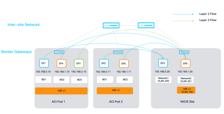
While there only exists endpoints in the third network on the ACI site, there are two ways to allow connectivity when the NX-OS site is policy unaware:
1. The network configuration for Network 3 can be deployed on the NX-OS site so that the importing of route targets for that network can be deployed. Since there has been no change in the configuration on Nexus Dashboard from the previous section, the network deployment for Network3 and the IP Gateway of 192.168.2.1 has been omitted. Once the VXLAN Stretch configuration for BD3 has been created, the ACI BGWs will advertise type-2 routes for any endpoint within that BD, and the remote VXLAN fabric will import and advertise them locally.
Note: If the remote NX-OS fabric is policy aware, this step is required to correctly apply SGT tags to type-2 endpoints.
2. Another option is to check the “Advertise Externally” flag on the subnet defined under BD3, while leaving only the VRF stretched with no local deployment of Network3 on NX-OS. This flag enables the ACI BGWs to export the type-5 network route to the NX-OS BGW. This is what was done in this example.
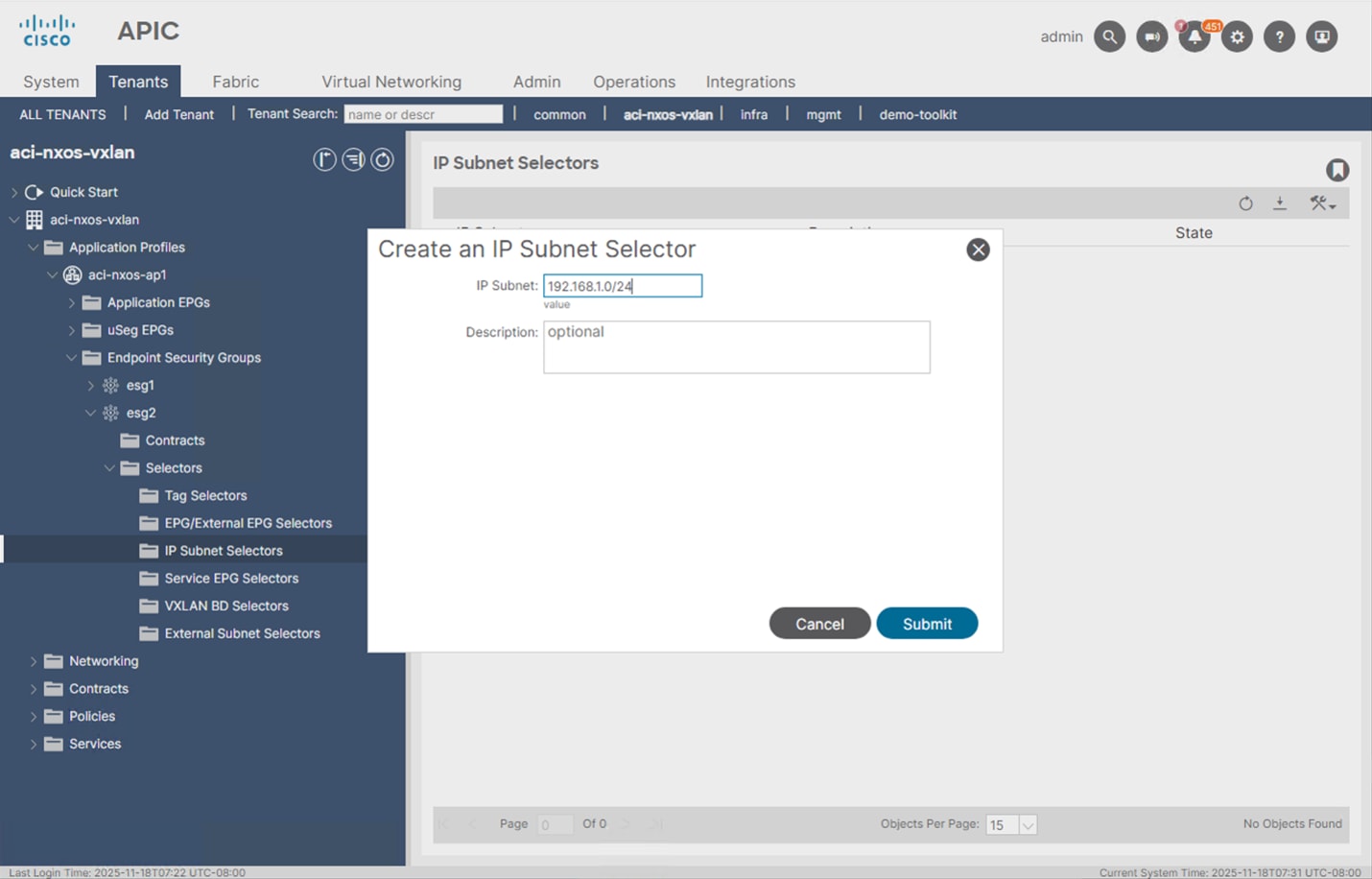
In addition to the previous steps, another classifier is needed under the ESG to classify IP Subnets of the remote VXLAN EVPN fabric on APIC, instead of simply adding the VXLAN Stretch configuration for the Bridge Domain. This IP classification ensures that remotely learned EVPN IP prefixes can be correctly mapped to an ESG. From there, contracts need to be created between the relevant ESG’s to allow specific communication. The following figures provide the ESG configuration required on both esg2 and esg3 to allow Layer-3 communication between them.
First, esg2 needs to have an IP selector configured so that remote IP addresses in this network learned from BGP EVPN can be correctly classified in this esg. The entire /24 subnet is used but the length of this match can be extended all the way to single /32 host entries learned as type-2 routes.
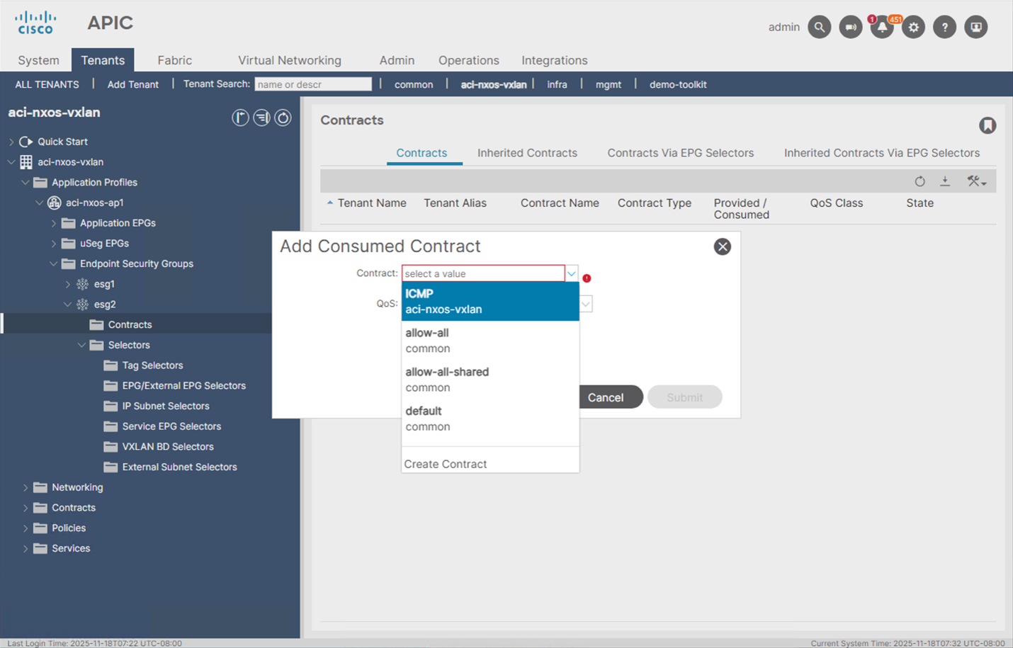
Because the endpoints requiring Layer-3 communication will also be in different ESGs, a contract is required to allow communication. In this example, we will allow ICMP between them by selecting a previously created ICMP contract within the tenant as the consumer on esg2.
The third network with subnet 192.168.2.0/24 now needs ESG configuration to map the EPG, and contract. We do not need VXLAN BD or IP Selectors because the network is only local to ACI. The below figures show the configuration steps to do this.
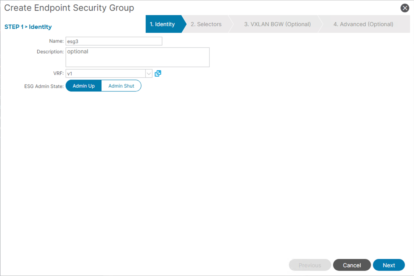
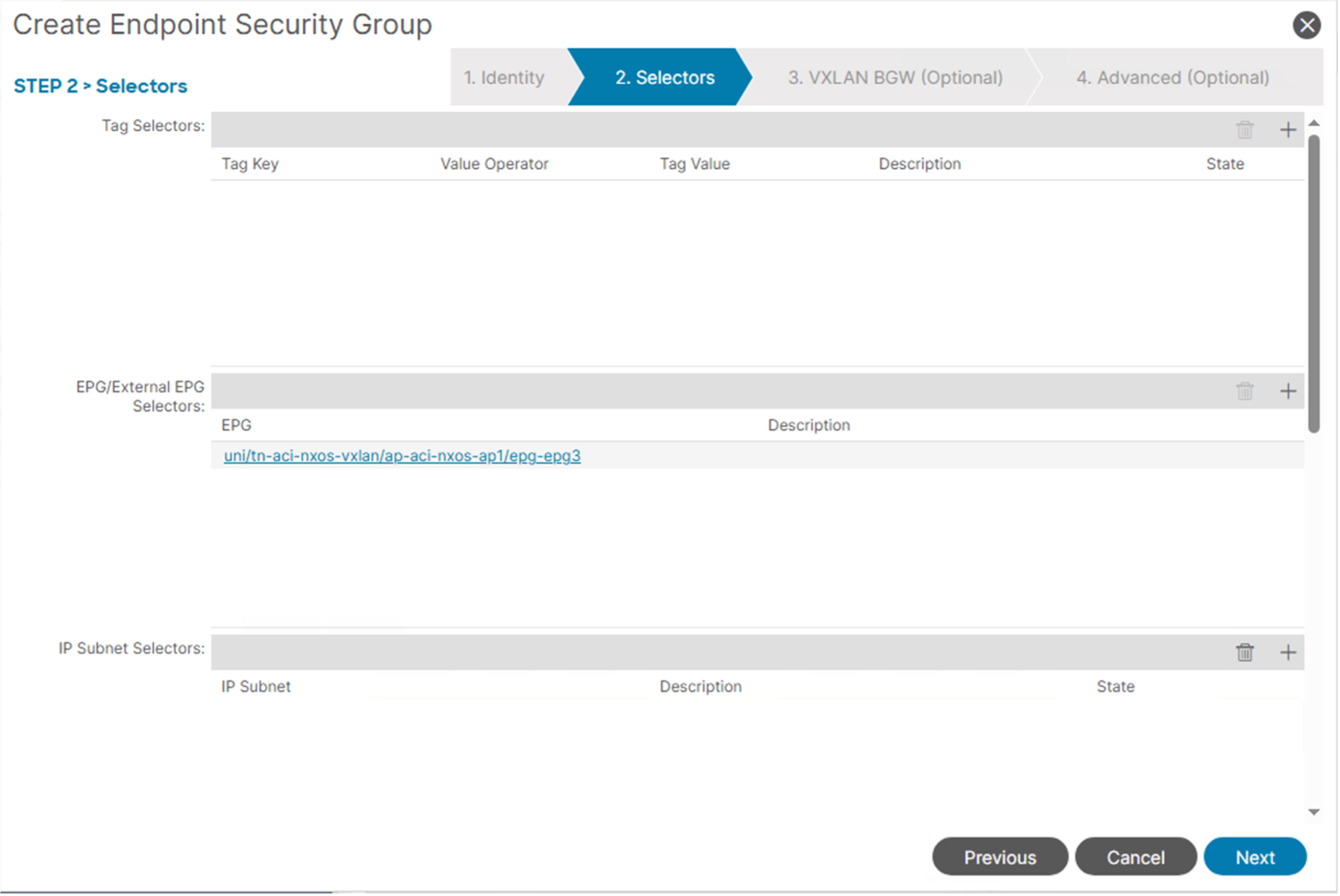

Once this configuration is in place, reachability from devices in EPG2 with IP addresses 192.168.1.0/24 to devices in EPG3 with IP Addresses 192.168.2.0/24 across pods and across sites should be established.
After the config is deployed, connectivity between the endpoints in BD2/Network2 and BD3/Network3 should be established. For verification purposes, we can check the BGP control plane to see if the remote L3 entries for Network2 are learned on each ACI border gateway.
ACI Border Gateway (Both Pods):
aci-bgw1# show bgp l2vpn evpn 192.168.1.20 vrf overlay-1
Route Distinguisher: 65002:201
BGP routing table entry for [2]:[0]:[0]:[48]:[0050.569c.c370]:[32]:[192.168.1.20]/272, version 1036 dest ptr 0x9c329aba
Paths: (1 available, best #1)
Flags: (0x0000000000000202 0000000000) on xmit-list, is not in rib/evpn, is not in HW, is locked
Multipath: eBGP iBGP
Advertised path-id 1
Path type (0x909e03f0): external 0x40000028 0x4002000 ref 2 adv path ref 1, path is valid, is best path, remote nh not installed
Imported to 2 destination(s)
AS-Path: 65002 , path sourced external to AS
202.202.202.202 (metric 0) from 10.2.0.3 (10.2.0.3)
Origin IGP, MED 2000, localpref 100, weight 0 tag 4294966000, propagate 0, floating svi 0, tunnel resolved 0
Received label 201 100
Extcommunity:
RT:65100:100
RT:65100:201
SOO:65100:1291845613
COST:pre-bestpath:170:1610612736
ENCAP:8
0x310:03100000:0000fdea
Router MAC:0200.caca.caca
Path-id 1 not advertised to any peer
Route Distinguisher: 1:31719393 (L2VNI 14942177)
BGP routing table entry for [2]:[0]:[0]:[48]:[0050.569c.c370]:[32]:[192.168.1.20]/272, version 1037 dest ptr 0x9c32a786
Paths: (1 available, best #1)
Flags: (0x0000000000000212 0000000000) on xmit-list, is in rib/evpn, is not in HW
Multipath: eBGP iBGP
Advertised path-id 1
Path type (0x90dd04c4): external 0xc0000028 0x400 ref 0 adv path ref 1, path is valid, is best path, remote nh not installed, in rib
Imported from (0x909e03f0) 65002:201:[2]:[0]:[0]:[48]:[0050.569c.c370]:[32]:[192.168.1.20]/144
AS-Path: 65002 , path sourced external to AS
202.202.202.202 (metric 0) from 10.2.0.3 (10.2.0.3)
Origin IGP, MED 2000, localpref 100, weight 0 tag 4294966000, propagate 0, floating svi 0, tunnel resolved 0
Received label 201 100
Extcommunity:
RT:65100:100
RT:65100:201
SOO:65100:1291845613
COST:pre-bestpath:170:1610612736
ENCAP:8
0x310:03100000:0000fdea
Router MAC:0200.caca.caca
Path-id 1 advertised to peers:
130.10.56.65 130.10.56.66
NX-OS Border Gateway
Note that in this case we are checking for the type-5 route because “advertise externally” flag was enabled on the bridge domain to advertise type-5 to NX-OS. This is because BD3/Network3 is not deployed on NX-OS and is only on ACI.
nx-bgw# show bgp l2vpn evpn 192.168.2.0
BGP routing table information for VRF default, address family L2VPN EVPN
Route Distinguisher: 1:19660800
BGP routing table entry for [5]:[0]:[0]:[24]:[192.168.2.0]/224, version 3782
Paths: (1 available, best #1)
Flags: (0x000002) (high32 00000000) on xmit-list, is not in l2rib/evpn, is not in HW
Advertised path-id 1
Path type: external, path is valid, is best path, no labeled nexthop
Imported to 1 destination(s)
Imported paths list: v1
Gateway IP: 0.0.0.0
AS-Path: 65100 , path sourced external to AS
101.101.101.101 (metric 0) from 105.105.105.105 (130.10.240.32)
Origin incomplete, MED 0, localpref 100, weight 0
Received label 100
Extcommunity: RT:65002:100 ENCAP:8 PCTAG:0:80:1 Router MAC:000c.0c0c.0c0c
Path-id 1 not advertised to any peer
Route Distinguisher: 10.2.0.3:17 (L3VNI 100)
BGP routing table entry for [5]:[0]:[0]:[24]:[192.168.2.0]/224, version 3804
Paths: (1 available, best #1)
Flags: (0x000002) (high32 0x000400) on xmit-list, is not in l2rib/evpn
Advertised path-id 1
Path type: local, path is valid, is best path, reoriginated, no labeled nexthop
Gateway IP: 0.0.0.0
AS-Path: 65100 , path sourced external to AS
10.3.0.3 (metric 0) from 0.0.0.0 (10.2.0.3)
Origin incomplete, MED 0, localpref 100, weight 0
Received label 100
Extcommunity: RT:65002:100 ENCAP:8 PCTAG:0:0:1 Site-ID:0:0
Router MAC:bcd2.9589.4873
Path-id 1 (dual) advertised to peers:
10.2.0.4
Route Distinguisher: 1:36438016
BGP routing table entry for [5]:[0]:[0]:[24]:[192.168.2.0]/224, version 3784
Paths: (1 available, best #1)
Flags: (0x000002) (high32 00000000) on xmit-list, is not in l2rib/evpn, is not in HW
Advertised path-id 1
Path type: external, path is valid, is best path, no labeled nexthop
Imported to 1 destination(s)
Imported paths list: v1
Gateway IP: 0.0.0.0
AS-Path: 65100 , path sourced external to AS
102.102.102.102 (metric 0) from 106.106.106.106 (130.13.0.161)
Origin incomplete, MED 0, localpref 100, weight 0
Received label 100
Extcommunity: RT:65002:100 ENCAP:8 PCTAG:0:80:1 Router MAC:000c.0c0c.0c0c
Path-id 1 not advertised to any peer
With the control plane established, we can also verify the VNI translation for the VRF on the ACI border gateway to ensure that the VNI values assigned to the VRF (100) on NX-OS are correctly mapped to the VNI assigned by APIC on the ACI fabric:
(same for both aci border gateways)
aci-bgw1# vsh_lc -c "show system internal eltmc info vrf aci-nxos-vxlan:v1"
VRF-TABLE: aci-nxos-vxlan:v1
vrf_type: tenant ::: context_id: 10
overlay_index: 0 ::: vnid: 2883584
scope: 2883584 ::: sclass: 32770
remote_vnid: 100 ::: remote_vnid_hex: 0x64
v4_table_id: 0xa ::: v6_table_id: 0x8000000a
Finally, we can verify the contract relationships between the two endpoints on the border gateway(s). We should have a contract relationship deployed between ESG2 (matching stretched VNI, IP Selector, and EPG) and ESG3 (EPG). Since this flow is routed (L3), the border gateway will need to have the subnet for ESG2 (192.168.1.0/24) programmed with the correct PCtag of ESG2. This can be verified by running the following command on the border gateway:
aci-bgw1# vsh -c "show system internal policy-mgr prefix"
Requested prefix data
Vrf-Vni VRF-Id Table-Id Table-State VRF-Name Addr Class Shared Remote Complete Svc_ena Connected_Subnet
======= ====== =========== ======= ============================ ================================= ====== ====== ====== ======== ========
2981888 2 0x2 Up management 0.0.0.0/0 32770 False False False False False
3014656 5 0x80000005 Up mgmt:inb ::/0 15 False False False False False
3014656 5 0x5 Up mgmt:inb 0.0.0.0/0 15 False False False False False
2883584 10 0x8000000a Up aci-nxos-vxlan:v1 ::/0 15 False False False False False
2883584 10 0xa Up aci-nxos-vxlan:v1 0.0.0.0/0 15 False False False False False
2883584 10 0xa Up aci-nxos-vxlan:v1 100.100.100.100/32 25 False False False False False
2883584 10 0xa Up aci-nxos-vxlan:v1 192.168.1.0/24 10938 False False False False True <--
Alternatively, the pcTag for ESG3, can be validated via UI.
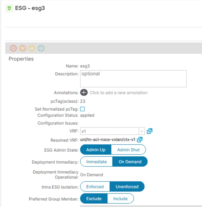
With the pcTag information (10938 for ESG2 matching IP Selector and 23 for ESG3), we can check if there is a valid contract between the two ESGs that allows the traffic (ICMP in this case).
aci-bgw1# show zoning-rule scope 2883584 src-epg 10938 dst-epg 23
+---------+--------+--------+----------+--------+---------+---------+---------------------+--------+---------------+
| Rule ID | SrcEPG | DstEPG | FilterID | Dir | operSt | Scope | Name | Action | Priority |
+---------+--------+--------+----------+--------+---------+---------+---------------------+--------+---------------+
| 4116 | 10938 | 23 | 2 | bi-dir | enabled | 2883584 | aci-NX-OS-vxlan:ICMP | permit | fully_qual(7) |
+---------+--------+--------+----------+--------+---------+---------+---------------------+--------+---------------+
With the control plane routes advertised, correct VNI translations, and contracts that allow communication, communication should be established using ICMP.
Endpoint Mobility Considerations
Most data center fabrics are designed with host mobility in mind, allowing endpoints to move between switches and interfaces to provide failover and redundancy. This also extends to multi-site architectures, where high availability and disaster recovery becomes a critical use case of the architecture.
Given that this architecture consists of both ACI and NX-OS fabrics, it is important to understand what configuration and design options are needed to ensure endpoint mobility between architectures without packet loss.
By default, ACI switches use 0022.bdf9.19ff as the router MAC address for all bridge domains. This can be verified by creating any new bridge domain and viewing the layer-3 configurations.
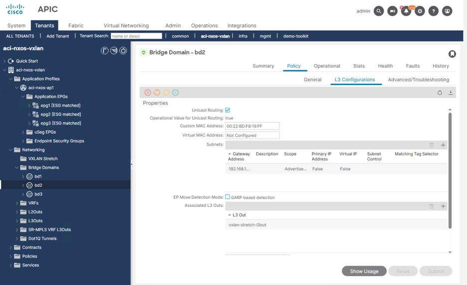
Assuming that the subnet IP configured under the bridge domain is the IP used as the default gateway for the endpoint, the host will learn this MAC address as the default gateway MAC and associate it to the gateway IP in its ARP table. This way, when traffic is routed from the host, and sent to this destination MAC, the ingress leaf switch will know to route the frame. ACI allows each bridge domain to have a custom MAC address if there exists a need, with the primary use case migrating the gateway for a segment to and from ACI and wanting to ensure the two gateway MAC addresses match.
In VXLAN EVPN fabrics, a single router MAC is used fabric wide. By default, when using Nexus Dashboard to deploy the fabric, the template will deploy 2020.0000.00aa as the router MAC address for all layer-3 enabled VNIs. This is verified by navigating to Manage > Fabric > Actions > Edit fabric settings > Fabric Management > General Parameters > Anycast Gateway MAC.
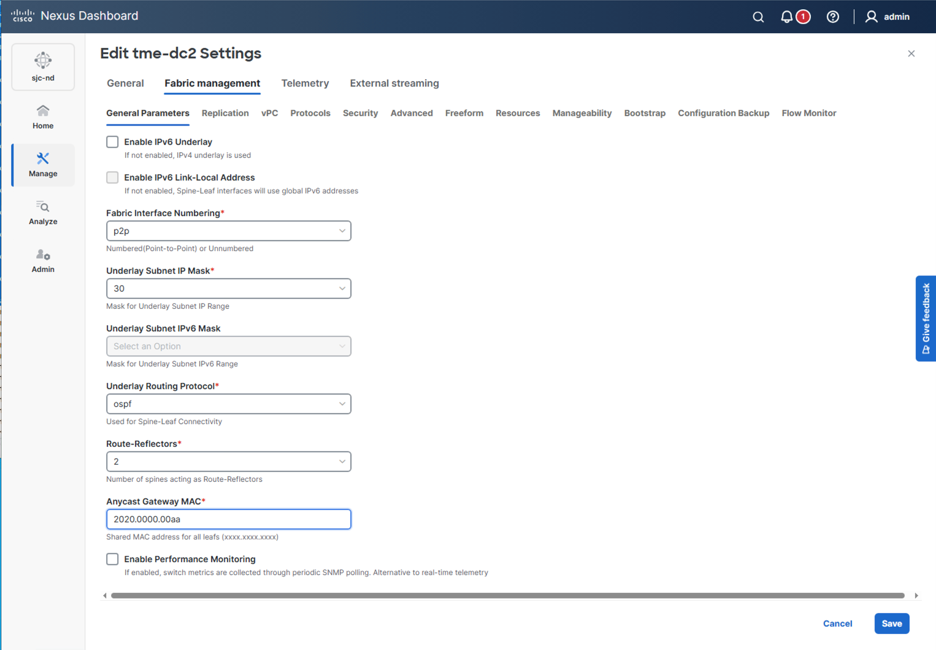
If seamless endpoint mobility is required across architectures, it is critical that any stretched network maintain the same router MAC address so that the host cache does not need to be updated after a move. Since VXLAN EVPN deploys a fabric wide MAC, and it is potentially disruptive to change it when there are existing endpoints and networks, there are two options:
1. For any ACI bridge domain that is stretched, or participating in endpoint mobility between sites, ensure the Custom MAC Address under the bridge domain is configured the same as the VXLAN EVPN Anycast Gateway MAC. This is ideal for scenarios where a brownfield fabric with existing endpoints and networks exists because it does not require changing the gateway MAC for the entire fabric. Instead, one BD at a time can be updated.
2. Change the VXLAN EVPN Anycast Gateway MAC to the default 0022.bdf8.19ff so that the MAC addresses match fabric wide by default. This is ideal for scenarios where a greenfield fabric is being deployed because the gateway MAC can be updated without impact before the deployment of endpoints and networks.
ACI Layer-3 Routing and Prefix Advertisement
Beyond the east-west traffic flows that have been configured, Layer-3 prefixes injected from external routers in each fabric domain can be introduced. These prefixes can be used to advertise external reachability to hosts in any VXLAN fabric connected through the BGWs for Multi-Site. In this example, a single prefix 100.100.100.100/32 is being injected into the ACI fabric in Pod-1 via an L3Out in the same tenant:aci-NX-OS-vxlan, and same VRF: aci-nxos-vxlan:v1. The purpose of this is to illustrate how endpoints in the remote fabrics can reach the external prefixes via the ACI fabric.
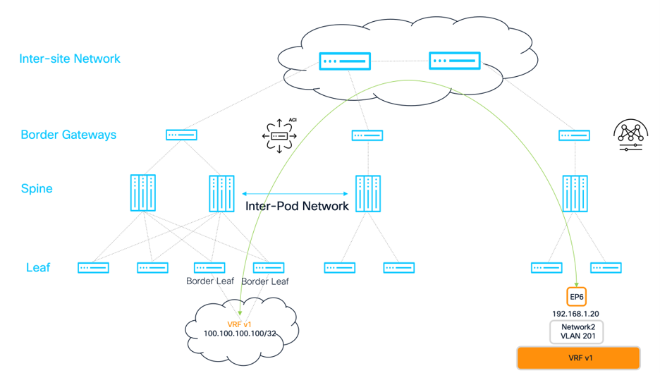
When the external prefix is injected from the external router, the BGP domain will implicitly advertise the prefix to the remote site via EVPN. This means that the route will be learnt locally in the ACI fabric and pods, as well as advertised remotely to the NX-OS EVPN site sourced from the border gateway in the pod that is learning the prefix. The figure below shows the routing path for the inject route across the devices in the domain.
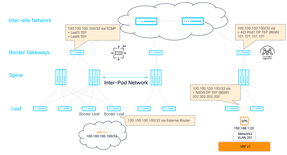
Once the route has been learned on the border leafs from the external router, ESG policy will need to be configured to allow communication between the external prefix 100.100.100.100, and the Endpoint in the NX-OS site. The endpoint in the NX-OS site is already matched to ESG esg2 with the use of the IP Selector matching subnet 192.168.1.0/24. An ESG is created that represents the routes injected locally into the ACI fabric. The VRF v1 is matched.
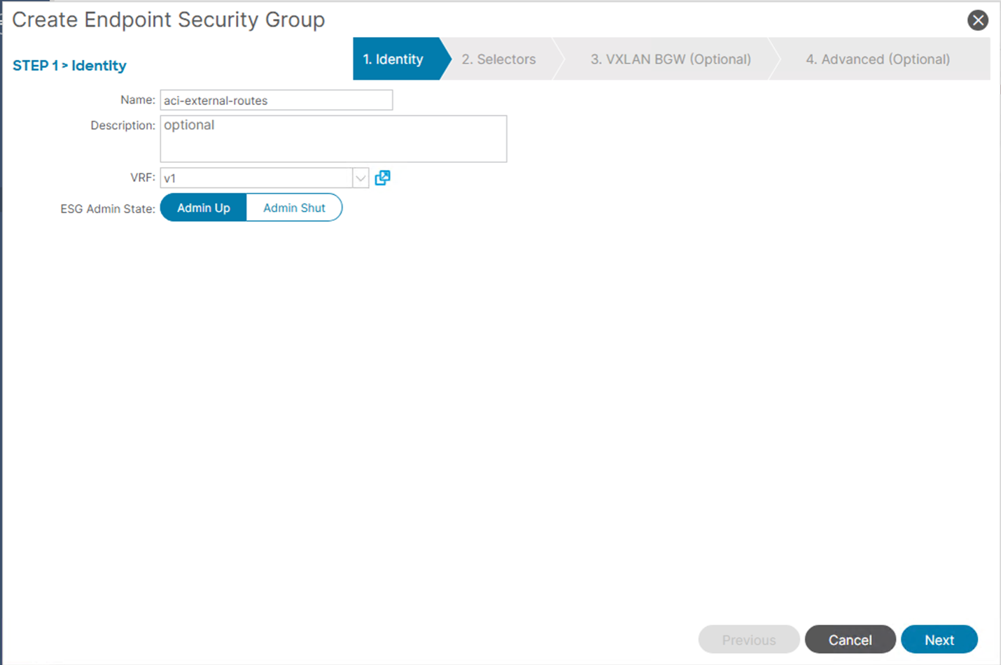
Additionally, an “External Subnet Selector” is added to match the externally learned prefix to the current ESG. This will allow the prefix to be assigned a unique pcTag for this ESG, which we can then assign contract policy towards esg2.
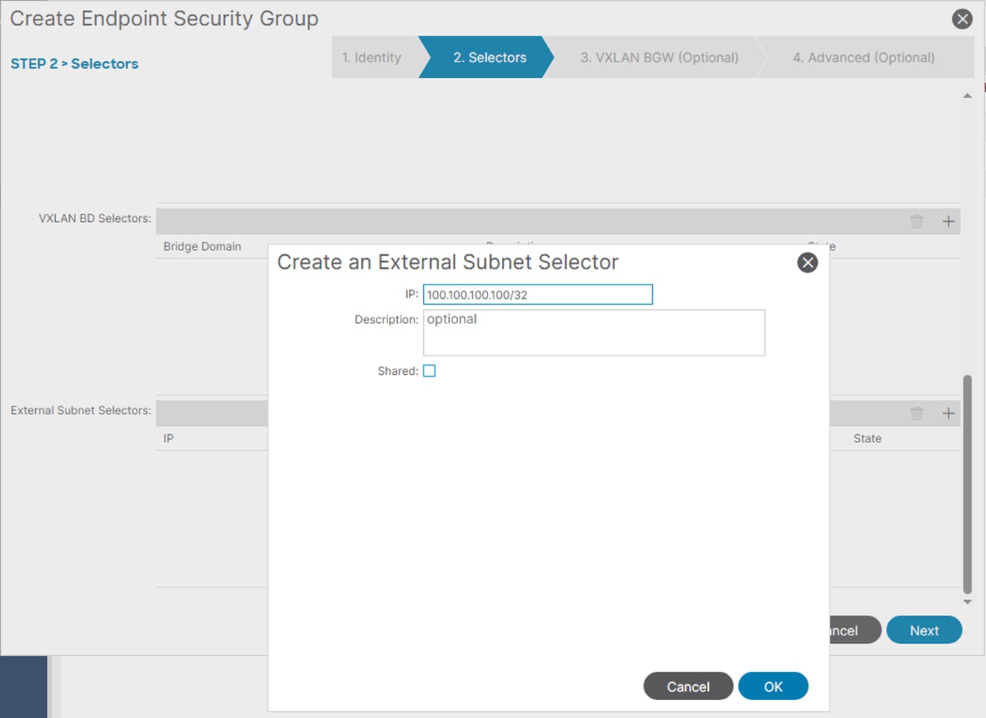
Finally, once a contract is associated between ESG aci-external-routes and ESG esg2, communication that matches that contract will be allowed between the external prefix 100.100.100.100/32, and any endpoint that resides within the 192.168.1.0/24 subnet, including 192.168.1.20 learnt remotely from the NX-OS EVPN Fabric.
Note: Normal Layer-3 out rules still apply, and the 192.168.1.0/24 subnet must also be advertised to the external router to ensure bi-directional communication, unless there is a lesser prefix route like a default route. This is accomplished using standard advertisement features within APIC, or static routes. Please refer the ACI Layer-3 Out whitepaper for more information.
After the config is deployed, connectivity between the endpoints in BD2/Network2 and the external prefix injected into the ACI site with IP address 100.100.100.100 should be established. For verification purposes, we can check the BGP control plane to see if the remote L3 entries for both networks are learned on each border gateway.
ACI Border Gateway (Both Pods):
aci-bgw1# show bgp l2vpn evpn 192.168.1.20 vrf overlay-1
Route Distinguisher: 65002:201
BGP routing table entry for [2]:[0]:[0]:[48]:[0050.569c.c370]:[32]:[192.168.1.20]/272, version 1036 dest ptr 0x9c329aba
Paths: (1 available, best #1)
Flags: (0x0000000000000202 0000000000) on xmit-list, is not in rib/evpn, is not in HW, is locked
Multipath: eBGP iBGP
Advertised path-id 1
Path type (0x909e03f0): external 0x40000028 0x4002000 ref 2 adv path ref 1, path is valid, is best path, remote nh not installed
Imported to 2 destination(s)
AS-Path: 65002 , path sourced external to AS
202.202.202.202 (metric 0) from 10.2.0.3 (10.2.0.3)
Origin IGP, MED 2000, localpref 100, weight 0 tag 4294966000, propagate 0, floating svi 0, tunnel resolved 0
Received label 201 100
Extcommunity:
RT:65100:100
RT:65100:201
SOO:65100:1291845613
COST:pre-bestpath:170:1610612736
ENCAP:8
0x310:03100000:0000fdea
Router MAC:0200.caca.caca
Path-id 1 not advertised to any peer
Route Distinguisher: 1:31719393 (L2VNI 14942177)
BGP routing table entry for [2]:[0]:[0]:[48]:[0050.569c.c370]:[32]:[192.168.1.20]/272, version 1037 dest ptr 0x9c32a786
Paths: (1 available, best #1)
Flags: (0x0000000000000212 0000000000) on xmit-list, is in rib/evpn, is not in HW
Multipath: eBGP iBGP
Advertised path-id 1
Path type (0x90dd04c4): external 0xc0000028 0x400 ref 0 adv path ref 1, path is valid, is best path, remote nh not installed, in rib
Imported from (0x909e03f0) 65002:201:[2]:[0]:[0]:[48]:[0050.569c.c370]:[32]:[192.168.1.20]/144
AS-Path: 65002 , path sourced external to AS
202.202.202.202 (metric 0) from 10.2.0.3 (10.2.0.3)
Origin IGP, MED 2000, localpref 100, weight 0 tag 4294966000, propagate 0, floating svi 0, tunnel resolved 0
Received label 201 100
Extcommunity:
RT:65100:100
RT:65100:201
SOO:65100:1291845613
COST:pre-bestpath:170:1610612736
ENCAP:8
0x310:03100000:0000fdea
Router MAC:0200.caca.caca
Path-id 1 advertised to peers:
130.10.56.65 130.10.56.66
NX-OS Border Gateway
nx-bgw# show bgp l2vpn evpn 100.100.100.100
BGP routing table information for VRF default, address family L2VPN EVPN
Route Distinguisher: 1:19660800
BGP routing table entry for [5]:[0]:[0]:[32]:[100.100.100.100]/224, version 877
Paths: (1 available, best #1)
Flags: (0x000002) (high32 00000000) on xmit-list, is not in l2rib/evpn, is not in HW
Advertised path-id 1
Path type: external, path is valid, is best path, no labeled nexthop
Imported to 1 destination(s)
Imported paths list: v1
Gateway IP: 0.0.0.0
AS-Path: 65100 65005 , path sourced external to AS
101.101.101.101 (metric 0) from 105.105.105.105 (130.10.240.32)
Origin IGP, MED not set, localpref 100, weight 0
Received label 100
Extcommunity: RT:65002:100 ENCAP:8 PCTAG:0:80:0 Router MAC:000c.0c0c.0c0c
Path-id 1 not advertised to any peer
Route Distinguisher: 10.2.0.3:17 (L3VNI 100)
BGP routing table entry for [5]:[0]:[0]:[32]:[100.100.100.100]/224, version 889
Paths: (1 available, best #1)
Flags: (0x000002) (high32 0x000400) on xmit-list, is not in l2rib/evpn
Advertised path-id 1
Path type: local, path is valid, is best path, reoriginated, no labeled nexthop
Gateway IP: 0.0.0.0
AS-Path: 65100 65005 , path sourced external to AS
10.3.0.3 (metric 0) from 0.0.0.0 (10.2.0.3)
Origin IGP, MED not set, localpref 100, weight 0
Received label 100
Extcommunity: RT:65002:100 ENCAP:8 PCTAG:0:80:0 Site-ID:0:0
Router MAC:bcd2.9589.4873
Path-id 1 (dual) advertised to peers:
10.2.0.4
With the control plane established, we can also verify the VNI translation for the VRF on the ACI border gateway to ensure that the VNI values assigned to the VRF (100) on NX-OS are correctly mapped to the VNI assigned by APIC on the ACI fabric:
(same for both aci border gateways)
aci-bgw1# vsh_lc -c "show system internal eltmc info vrf aci-nxos-vxlan:v1"
VRF-TABLE: aci-nxos-vxlan:v1
vrf_type: tenant ::: context_id: 10
overlay_index: 0 ::: vnid: 2883584
scope: 2883584 ::: sclass: 32770
remote_vnid: 100 ::: remote_vnid_hex: 0x64
v4_table_id: 0xa ::: v6_table_id: 0x8000000a
Finally, we can verify the contract relationships between the external prefix and ESG2 on the border leafs. We should have a contract relationship deployed between ESG2 (matching stretched L2 VNI and Subnet 192.168.1.0/24) and ESG aci-external-routes (matching external subnet selector with 100.100.100.100/32). We can validate the pcTag programming for each IP subnet in the respective VRF by checking the policy prefix configuration on each border gateway:
aci-bgw1# vsh -c "show system internal policy-mgr prefix"
Requested prefix data
Vrf-Vni VRF-Id Table-Id Table-State VRF-Name Addr Class Shared Remote Complete Svc_ena Connected_Subnet
======= ====== =========== ======= ============================ ================================= ====== ====== ====== ======== ========
2981888 2 0x2 Up management 0.0.0.0/0 32770 False False False False False
3014656 5 0x80000005 Up mgmt:inb ::/0 15 False False False False False
3014656 5 0x5 Up mgmt:inb 0.0.0.0/0 15 False False False False False
2883584 10 0x8000000a Up aci-nxos-vxlan:v1 ::/0 15 False False False False False
2883584 10 0xa Up aci-nxos-vxlan:v1 0.0.0.0/0 15 False False False False False
2883584 10 0xa Up aci-nxos-vxlan:v1 100.100.100.100/32 25 False False False False False <--
2883584 10 0xa Up aci-nxos-vxlan:v1 192.168.1.0/24 10938 False False False False True <--
2883584 10 0xa Up aci-nxos-vxlan:v1 192.168.2.0/24 23 False False False False True
With the pcTag information, we can check if there is a validation contract between the two ESGs that allow the traffic (ICMP in this case).
aci-bgw1# show zoning-rule scope 2883584 src-epg 25 dst-epg 10938
+---------+--------+--------+----------+--------+---------+---------+---------------------+--------+---------------+
| Rule ID | SrcEPG | DstEPG | FilterID | Dir | operSt | Scope | Name | Action | Priority |
+---------+--------+--------+----------+--------+---------+---------+---------------------+--------+---------------+
| 4120 | 25 | 10938 | 2 | bi-dir | enabled | 2883584 | aci-NX-OS-vxlan:ICMP | permit | fully_qual(7) |
+---------+--------+--------+----------+--------+---------+---------+---------------------+--------+---------------+
With the control plane routes advertised, correct VNI translations, and contracts that allow communication, traffic should be established using ICMP.
NX-OS Layer-3 Routing and Prefix Advertisement
Similarly to the previous example where an external prefix is advertised on the ACI site towards the NX-OS site, the reverse can also happen. In this example, a single prefix 111.111.111.111/32 is being injected into the NX-OS fabric via the border gateway in VRF v1. The purpose of this is to illustrate how endpoints in the ACI fabric can reach the external prefixes via the remote VXLAN EVPN fabric.
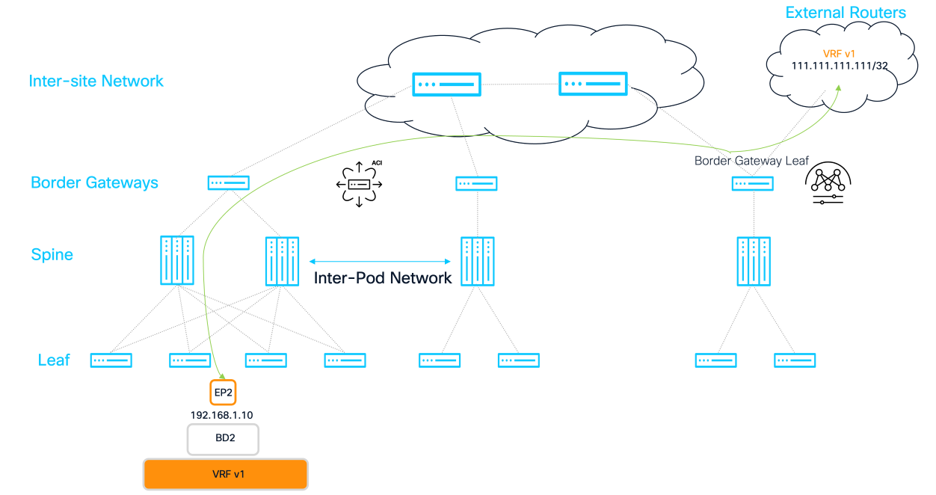
When the external prefix is injected from the external router, the BGP domain will implicitly advertise the prefix to the remote ACI site via EVPN. This means that the route will be learnt locally in the NX-OS fabric, as well as advertised remotely to the ACI fabric. The figure below shows the routing path for the inject route across the devices in the domain.
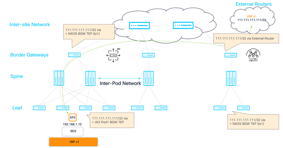
Once the route has been learned on the border gateway leaf from the external router in the NX-OS site and advertised to the border gateway in the ACI site, an ESG policy will need to be configured to allow communication between the external prefix 111.111.111.111, and the Endpoint in the ACI site that is already mapped to the ESG esg2. An ESG is created that represents the routes injected remotely from the NX-OS site. The VRF v1 is matched.
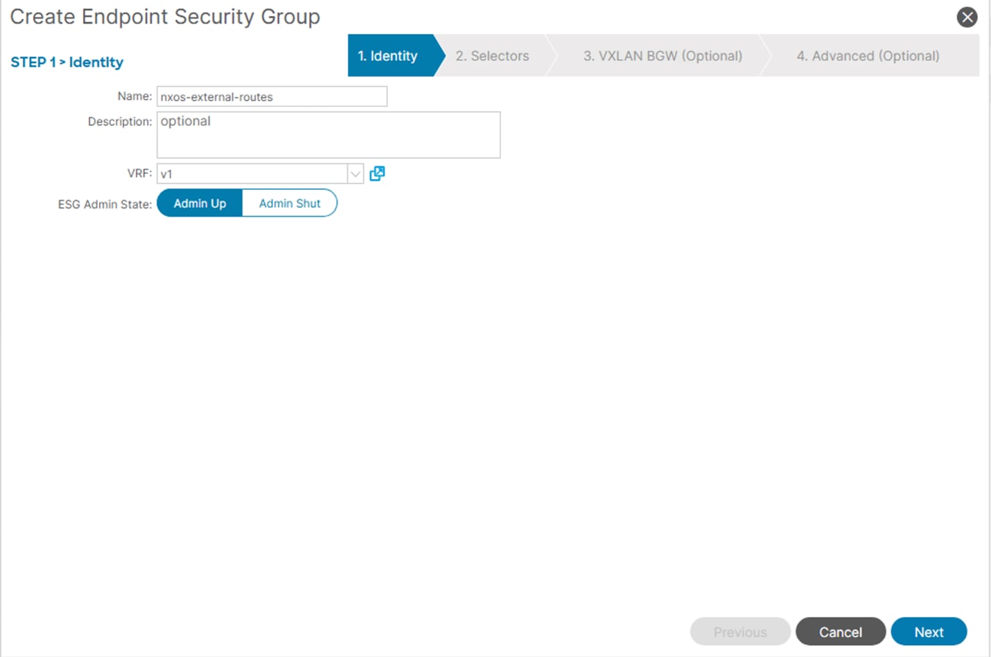
Just like the prefix injected from the ACI site, an “External Subnet Selector” is added to match the externally learned prefix on the NX-OS site to the current ESG. This will allow the prefix to be assigned a unique pcTag for this ESG, which we can then assign contract policy towards esg2.
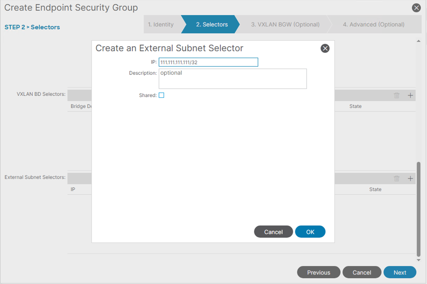
Finally, once a contract is associated between ESG NX-OS-external-routes and ESG esg2, communication that matches that contract will be allowed between the external prefix 111.111.111.111/32, and any endpoint that resides within the 192.168.1.0/24 subnet, including 192.168.1.20 learnt remotely from the NX-OS EVPN Fabric.
Note: Normal Layer-3 out rules still apply, and the 192.168.1.0/24 subnet must also be advertised to the external router to ensure bi-directional communication, unless there is a lesser prefix route like a default route. This is accomplished using standard advertisement features within NX-OS/ND, including route-maps, or static routes.
After the config is deployed, connectivity between the endpoints in BD2/Network2 and the external prefix injected into the NX-OS site, then advertised to the ACI site with IP address 111.111.111.111 should be established. For verification purposes, we can check the BGP control plane to see if the remote L3 entries for both networks are learned on each border gateway. The difference between this example, and the Type-2 or Type-5 routes advertised in the host networks, is that remote prefixes will be advertised by EVPN and learned on the ACI border gateways but then re-originated into MP-BGP VPNv4 in the tenant VRF and advertised to the spines. Because of this, verification requires checking the presence of the route via EVPN and then checking the presence of the route in the VPNv4 address family in the tenant VRF to ensure it is being advertised to the spines. Ya for Deployment guide gere
ACI Border Gateway (Both Pods):
aci-bgw1# show bgp l2vpn evpn 111.111.111.111 vrf overlay-1
Route Distinguisher: 10.2.0.3:17
BGP routing table entry for [5]:[0]:[0]:[32]:[111.111.111.111]:[0.0.0.0]/224, version 973 dest ptr 0x9c329454
Paths: (1 available, best #1)
Flags: (0x0000000000000002 0000000000) on xmit-list, is not in rib/evpn, is not in HW, is locked
Multipath: eBGP iBGP
Advertised path-id 1
Path type (0x909df9c8): external 0x40000028 0x4000000 ref 1 adv path ref 1, path is valid, is best path, remote nh not installed
Imported to 1 destination(s)
AS-Path: 65002 65005 , path sourced external to AS
10.3.0.3 (metric 0) from 10.2.0.3 (10.2.0.3)
Origin IGP, MED not set, localpref 100, weight 0 tag 4294966000, propagate 0, floating svi 0, tunnel resolved 0
Received label 100
Extcommunity:
RT:65100:100 ß RT with VNI of remote vxlan fabric
SOO:65100:1291845613
COST:pre-bestpath:170:1610612736
ENCAP:8
0x310:03100000:0000fdea
Router MAC:bcd2.9589.4873
Path-id 1 not advertised to any peer
aci-bgw1# show bgp vpnv4 unicast 111.111.111.111/32 vrf aci-nxos-vxlan:v1
BGP routing table information for VRF overlay-1, address family VPNv4 Unicast
Route Distinguisher: 501:2883584 (VRF aci-nxos-vxlan:v1)
BGP routing table entry for 111.111.111.111/32, version 65 dest ptr 0x90ec8598
Paths: (1 available, best #1)
Flags: (0x00000000000c001a 0000000000) on xmit-list, is in urib, is best urib route, is in HW, exported
vpn: version 548, (0x0000000000100002) on xmit-list
Multipath: eBGP iBGP
Advertised path-id 1, VPN AF advertised path-id 1
Path type (0x90dd0cc8): external 0xc0000028 0x400 ref 0 adv path ref 2, path is valid, is best path, remote nh not installed, in rib
Imported from (0x909df9c8) 10.2.0.3:17:[5]:[0]:[0]:[32]:[111.111.111.111]:[0.0.0.0]/120
AS-Path: 65002 65005 , path sourced external to AS
10.3.0.3 (metric 0) from 10.2.0.3 (10.2.0.3)
Origin IGP, MED not set, localpref 100, weight 0 tag 4294966000, propagate 0, floating svi 0, tunnel resolved 0
Received label 100
Extcommunity:
RT:65100:2883584 ß RT with VNI of local user VRF VNI in ACI (normalization)
SOO:65100:1291845613
COST:pre-bestpath:170:1610612736
ENCAP:8
0x310:03100000:0000fdea
VNID:2883584
VRF advertise information:
Path-id 1 not advertised to any peer
VPN AF advertise information:
Path-id 1 advertised to peers:
130.10.56.65 130.10.56.66 <- - - ACI Spine TEPs
NX-OS Border Gateway
nx-bgw# show bgp l2vpn evpn 111.111.111.111
BGP routing table information for VRF default, address family L2VPN EVPN
Route Distinguisher: 10.2.0.3:17 (L3VNI 100)
BGP routing table entry for [5]:[0]:[0]:[32]:[111.111.111.111]/224, version 3904
Paths: (1 available, best #1)
Flags: (0x000002) (high32 00000000) on xmit-list, is not in l2rib/evpn
Advertised path-id 1
Path type: local, path is valid, is best path, no labeled nexthop
Gateway IP: 0.0.0.0
AS-Path: 65005 , path sourced external to AS
10.3.0.3 (metric 0) from 0.0.0.0 (10.2.0.3)
Origin IGP, MED not set, localpref 100, weight 0
Received label 100
Extcommunity: RT:65002:100 ENCAP:8 Router MAC:bcd2.9589.4873
Path-id 1 advertised to peers:
10.2.0.4 105.105.105.105 106.106.106.106 <- - advertise to local spine and remote ACI Border Gateways
With the control plane established, we can also verify the VNI translation for the VRF on the ACI border gateway to ensure that the VNI values assigned to the VRF (100) on NX-OS are correctly mapped to the VNI assigned by APIC on the ACI fabric:
(same for both aci border gateways)
aci-bgw1# vsh_lc -c "show system internal eltmc info vrf aci-nxos-vxlan:v1"
VRF-TABLE: aci-nxos-vxlan:v1
vrf_type: tenant ::: context_id: 10
overlay_index: 0 ::: vnid: 2883584
scope: 2883584 ::: sclass: 32770
remote_vnid: 100 ::: remote_vnid_hex: 0x64
v4_table_id: 0xa ::: v6_table_id: 0x8000000a
Finally, we can verify the contract relationships between the external prefix and ESG2 on the border leafs. We should have a contract relationship deployed between ESG2 (matching stretched L2 VNI and Subnet 192.168.1.0/24) and ESG nxos-external-routes (matching external subnet selector with 111.111.111.111/32). We can validate the pcTag programming for each IP subnet in the respective VRF by checking the policy prefix configuration on each border gateway:
aci-bgw1# vsh -c "show system internal policy-mgr prefix"
Requested prefix data
Vrf-Vni VRF-Id Table-Id Table-State VRF-Name Addr Class Shared Remote Complete Svc_ena Connected_Subnet
======= ====== =========== ======= ============================ ================================= ====== ====== ====== ======== ========
2981888 2 0x2 Up management 0.0.0.0/0 32770 False False False False False
3014656 5 0x80000005 Up mgmt:inb ::/0 15 False False False False False
3014656 5 0x5 Up mgmt:inb 0.0.0.0/0 15 False False False False False
2883584 10 0x8000000a Up aci-nxos-vxlan:v1 ::/0 15 False False False False False
2883584 10 0xa Up aci-nxos-vxlan:v1 0.0.0.0/0 15 False False False False False
2883584 10 0xa Up aci-nxos-vxlan:v1 100.100.100.100/32 25 False False False False False
2883584 10 0xa Up aci-nxos-vxlan:v1 111.111.111.111/32 10939 False False False False False <--
2883584 10 0xa Up aci-nxos-vxlan:v1 192.168.1.0/24 10938 False False False False True <--
With the pcTag information, we can check if there is a valid contract between the two ESGs that allows the traffic (ICMP in this case).
aci-bgw1# show zoning-rule scope 2883584 src-epg 10939 dst-epg 10938
+---------+--------+--------+----------+----------------+---------+---------+---------------------+--------+---------------+
| Rule ID | SrcEPG | DstEPG | FilterID | Dir | operSt | Scope | Name | Action | Priority |
+---------+--------+--------+----------+----------------+---------+---------+---------------------+--------+---------------+
| 4125 | 10939 | 10938 | 2 | uni-dir-ignore | enabled | 2883584 | aci-NX-OS-vxlan:ICMP | permit | fully_qual(7) |
+---------+--------+--------+----------+----------------+---------+---------+---------------------+--------+---------------+
With the control plane routes advertised, correct VNI translations, and contracts that allow communication, traffic should be established using ICMP.
Transit routing refers to the ability to send traffic from end devices behind a layer-3 routed segment, between fabrics or sites. The Cisco Nexus One Fabric solution supports prefix advertisement between both ACI and NX-OS sites, and for traffic to be normalized, and classified between external subnets.
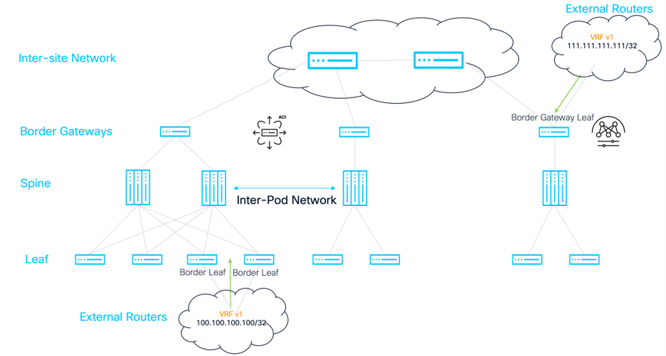
The assumption in this case is that the L3Out on APIC within the tenant, and the Layer-3 VRF-Lite configuration on Nexus Dashboard for NX-OS is already in place, like how the routes were advertised individually at each site in the previous two examples. If routes are being advertised within the respective sites and VRF, the only thing required is to map the prefixes to an ESG for policy enforcement using the External Subnet Selector on the ESG.
In the previous two examples where routes were injected at each site respectively, two ESGs were created to classify the local ACI learned prefix, and the remotely learned NX-OS prefix. Since these two ESGs are already classifying the traffic, all that is needed is to add a contract between them to allow communication. This is how this example is configured.
Alternatively, you could create a single ESG for all “transit” routes, named esg-transit-routes, and add both prefixes to the External Subnet Selector to match. Because they would be in the same ESG, communication would be allowed by default without a contract.
NOTE: Normal Layer-3 out rules still apply, and the 100.100.100.100/24 subnet must also be advertised to the external router in the NX-OS site to ensure bi-directional communication, unless there is a lesser prefix route like a default route. This is accomplished using standard advertisement features within NX-OS/ND, including route-maps, or static routes.
Furthermore, the 111.111.111.111 subnet must also be advertised to the external router in the ACI site to endure bi-directional communication, unless there is a lesser prefix route like a default route. This is accomplished using standard advertisement features within APIC, or static routes. For more information, see ACI L3Out whitepaper.
After the config is deployed, connectivity between the two external prefixes should be established. For verification purposes, we can check the BGP control plane to see if the remote L3 prefix entries for both sites are learned on the border gateways. The difference between this example, and the Type-2 or Type-5 routes advertised in the host networks, is that remote prefixes will be advertised by EVPN and learned on the ACI border gateways but then re-originated into MP-BGP VPNv4 in the tenant VRF and advertised to the spines. Because of this, verification on the ACI switches requires checking the presence of the route via EVPN and then checking the presence of the route in the VPNv4 address family in the tenant VRF to ensure it is being advertised to the spines.
ACI Border Gateway (Both Pods):
aci-bgw1# show bgp l2vpn evpn 111.111.111.111 vrf overlay-1
Route Distinguisher: 10.2.0.3:17
BGP routing table entry for [5]:[0]:[0]:[32]:[111.111.111.111]:[0.0.0.0]/224, version 973 dest ptr 0x9c329454
Paths: (1 available, best #1)
Flags: (0x0000000000000002 0000000000) on xmit-list, is not in rib/evpn, is not in HW, is locked
Multipath: eBGP iBGP
Advertised path-id 1
Path type (0x909df9c8): external 0x40000028 0x4000000 ref 1 adv path ref 1, path is valid, is best path, remote nh not installed
Imported to 1 destination(s)
AS-Path: 65002 65005 , path sourced external to AS
10.3.0.3 (metric 0) from 10.2.0.3 (10.2.0.3)
Origin IGP, MED not set, localpref 100, weight 0 tag 4294966000, propagate 0, floating svi 0, tunnel resolved 0
Received label 100
Extcommunity:
RT:65100:100
SOO:65100:1291845613
COST:pre-bestpath:170:1610612736
ENCAP:8
0x310:03100000:0000fdea
Router MAC:bcd2.9589.4873
Path-id 1 not advertised to any peer
aci-bgw1# show bgp vpnv4 unicast 111.111.111.111/32 vrf aci-nxos-vxlan:v1
BGP routing table information for VRF overlay-1, address family VPNv4 Unicast
Route Distinguisher: 501:2883584 (VRF aci-nxos-vxlan:v1)
BGP routing table entry for 111.111.111.111/32, version 65 dest ptr 0x90ec8598
Paths: (1 available, best #1)
Flags: (0x00000000000c001a 0000000000) on xmit-list, is in urib, is best urib route, is in HW, exported
vpn: version 548, (0x0000000000100002) on xmit-list
Multipath: eBGP iBGP
Advertised path-id 1, VPN AF advertised path-id 1
Path type (0x90dd0cc8): external 0xc0000028 0x400 ref 0 adv path ref 2, path is valid, is best path, remote nh not installed, in rib
Imported from (0x909df9c8) 10.2.0.3:17:[5]:[0]:[0]:[32]:[111.111.111.111]:[0.0.0.0]/120
AS-Path: 65002 65005 , path sourced external to AS
10.3.0.3 (metric 0) from 10.2.0.3 (10.2.0.3)
Origin IGP, MED not set, localpref 100, weight 0 tag 4294966000, propagate 0, floating svi 0, tunnel resolved 0
Received label 100
Extcommunity:
RT:65100:2883584
SOO:65100:1291845613
COST:pre-bestpath:170:1610612736
ENCAP:8
0x310:03100000:0000fdea
VNID:2883584
VRF advertise information:
Path-id 1 not advertised to any peer
VPN AF advertise information:
Path-id 1 advertised to peers:
130.10.56.65 130.10.56.66
NX-OS Border Gateway
nx-bgw# show bgp l2vpn evpn 100.100.100.100
BGP routing table information for VRF default, address family L2VPN EVPN
Route Distinguisher: 1:19660800
BGP routing table entry for [5]:[0]:[0]:[32]:[100.100.100.100]/224, version 877
Paths: (1 available, best #1)
Flags: (0x000002) (high32 00000000) on xmit-list, is not in l2rib/evpn, is not in HW
Advertised path-id 1
Path type: external, path is valid, is best path, no labeled nexthop
Imported to 1 destination(s)
Imported paths list: v1
Gateway IP: 0.0.0.0
AS-Path: 65100 65005 , path sourced external to AS
101.101.101.101 (metric 0) from 105.105.105.105 (130.10.240.32)
Origin IGP, MED not set, localpref 100, weight 0
Received label 100
Extcommunity: RT:65002:100 ENCAP:8 PCTAG:0:80:0 Router MAC:000c.0c0c.0c0c
Path-id 1 not advertised to any peer
Route Distinguisher: 10.2.0.3:17 (L3VNI 100)
BGP routing table entry for [5]:[0]:[0]:[32]:[100.100.100.100]/224, version 889
Paths: (1 available, best #1)
Flags: (0x000002) (high32 0x000400) on xmit-list, is not in l2rib/evpn
Advertised path-id 1
Path type: local, path is valid, is best path, reoriginated, no labeled nexthop
Gateway IP: 0.0.0.0
AS-Path: 65100 65005 , path sourced external to AS
10.3.0.3 (metric 0) from 0.0.0.0 (10.2.0.3)
Origin IGP, MED not set, localpref 100, weight 0
Received label 100
Extcommunity: RT:65002:100 ENCAP:8 PCTAG:0:80:0 Site-ID:0:0
Router MAC:bcd2.9589.4873
Path-id 1 (dual) advertised to peers:
10.2.0.4
With the control plane established, we can also verify the VNI translation for the VRF on the ACI border gateway to ensure that the VNI values assigned to the VRF (100) on NX-OS are correctly mapped to the VNI assigned by APIC on the ACI fabric:
(same for both aci border gateways)
aci-bgw1# vsh_lc -c "show system internal eltmc info vrf aci-nxos-vxlan:v1"
VRF-TABLE: aci-nxos-vxlan:v1
vrf_type: tenant ::: context_id: 10
overlay_index: 0 ::: vnid: 2883584
scope: 2883584 ::: sclass: 32770
remote_vnid: 100 ::: remote_vnid_hex: 0x64
v4_table_id: 0xa ::: v6_table_id: 0x8000000a
Finally, we can verify the contract relationships between the two prefixes on the border gateways. We should have a contract relationship deployed between both ESGs that matches the external subnet selector for each prefix, respectively. We can validate the pcTag programming for each IP subnet in the respective VRF by checking the policy prefix configuration on each border gateway:
aci-bgw1# vsh -c "show system internal policy-mgr prefix"
Requested prefix data
Vrf-Vni VRF-Id Table-Id Table-State VRF-Name Addr Class Shared Remote Complete Svc_ena Connected_Subnet
======= ====== =========== ======= ============================ ================================= ====== ====== ====== ======== ========
2981888 2 0x2 Up management 0.0.0.0/0 32770 False False False False False
3014656 5 0x80000005 Up mgmt:inb ::/0 15 False False False False False
3014656 5 0x5 Up mgmt:inb 0.0.0.0/0 15 False False False False False
2883584 10 0x8000000a Up aci-nxos-vxlan:v1 ::/0 15 False False False False False
2883584 10 0xa Up aci-nxos-vxlan:v1 0.0.0.0/0 15 False False False False False
2883584 10 0xa Up aci-nxos-vxlan:v1 100.100.100.100/32 25 False False False False False <--
2883584 10 0xa Up aci-nxos-vxlan:v1 111.111.111.111/32 10939 False False False False False <--
2883584 10 0xa Up aci-nxos-vxlan:v1 192.168.1.0/24 10938 False False False False True
With the pcTag information, we can check if there is a validate contract between the two ESGs that allows the traffic (ICMP in this case).
aci-bgw1# show zoning-rule scope 2883584 src-epg 25 dst-epg 10939
+---------+--------+--------+----------+--------+---------+---------+---------------------+--------+---------------+
| Rule ID | SrcEPG | DstEPG | FilterID | Dir | operSt | Scope | Name | Action | Priority |
+---------+--------+--------+----------+--------+---------+---------+---------------------+--------+---------------+
| 4126 | 25 | 10939 | 2 | bi-dir | enabled | 2883584 | aci-NX-OS-vxlan:ICMP | permit | fully_qual(7) |
+---------+--------+--------+----------+--------+---------+---------+---------------------+--------+---------------+
With the control plane routes advertised, correct VNI translations, and contracts that allow communication, traffic should be established using ICMP.
Both ACI and NX-OS fabrics have the ability to enforce policy using VXLAN, and leverage a combination of the control plane and data plane to ensure optimal forwarding, and utmost security based on user desired policies. Since Day-1, ACI has done this using EPGs and contracts, to assign a policy control tag (PCTag) to every EPG, and applying that tag in the iVXLAN header so that the source and destination switches can apply and enforce localized TCAM rules to allow or deny the traffic. This was later evolved for ESGs in the 5.2 release. Beginning with NX-OS 10.4(3), the standardized version of this implementation: VXLAN Group Policy Option (GPO), was introduced to allow network administrators to accomplish a similar segmentation strategy for VXLAN EVPN fabrics deployed using Nexus 9000 switches. However, the 10.6(1) release implemented a critical capability to allow MAC based segmentation and enforcement such that NX-OS and ACI fabrics can enforce security in the same way. Therefore, for end-to-end L2 and L3 policy enforcement, 10.6(1) and higher is required.
Now that ACI and NX-OS fabrics can be interconnected using VXLAN EVPN border gateways, having the ability to maintain security policies across fabrics and across implementations is critical. The intent of this section is not to do a deep dive on VXLAN GPO, but outline an example of how GPO and Security Group tags are mapped to ESGs to allow Paga normalization across sites. For a full deep dive on VXLAN GPO, and its deployment, please see the VXLAN GPO whitepaper.
Using the topology, endpoints, and configuration that was deployed in the above examples, the APIC will be configured to map ESG SGTs to remote SGTs learned via BGP EVPN on the remote VXLAN EVPN fabric. The goal is to allow L2 communication within the same network: Network2 (using IP address 192.168.1.0/24) when GPO is enabled, as well as isolate a single IP address: 192.168.1.21/32 into its own ESG to demonstrate a micro-segmentation use case.
NOTE: The isolated IP will only have policy applied at an IP level, meaning that only traffic that crosses the Layer3 boundary (outside of subnet 192.168.1.0/24) will have the policy applied. In order to ensure consistency between the SGT of the endpoints MAC and IP across the sites, MAC based segmentation would need to be configured on the NX-OS fabric which was released in 10.6(1). This ensures that the type-2 route for the MAC only contains the same SGT tag as the MAC/IP type-2 route when both MAC and IP selectors are defined.
As a counterpart of ESG2 in the ACI site, we will create the security group SG2 with SGT 10000 matching Network2 in the NX-OS site. Then, we will map SGT 10000 to ESG2 on ACI via the pcTag/SGT normalization such that EVPN routes with SGT 10000 from the NX-OS site are classified to the corresponding security group ESG2 on the ACI site. For SG10001, an additional security group will be created matching on the IP selector for the 192.168.1.21 IP, and a new ESG will be created to match the IP Selector and pcTag/SGT (10001) for the specific 192.168.1.21/32 IP.
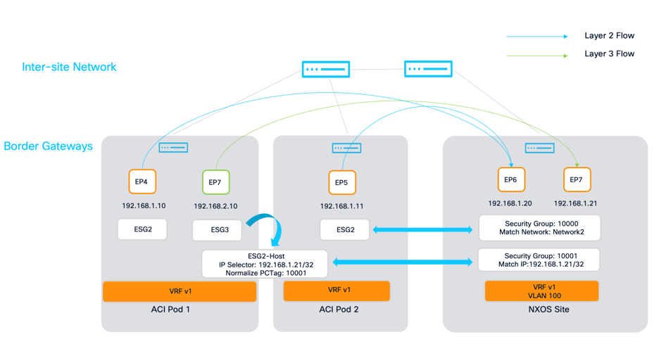
Before doing the configuration on APIC, the following shows how this GPO configuration is deployed within Nexus Dashboard. First, security groups must be enabled under the MSD level by navigating to Manage > Fabric Groups > MSD > Edit fabric group settings > Security.
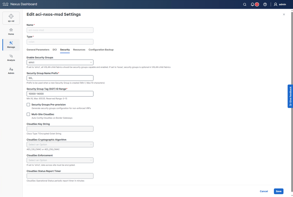
Once enabled, the VRF can be edited to configure a certain security enforcement action.
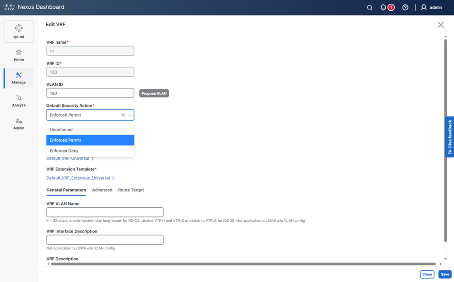
After the VRF is enabled, specific security groups can be configured, along with their matching selectors as well as SG tag allocation. For Network2, a network selector that matches the entire network can be created, as well as allocated SG Tag 10000.
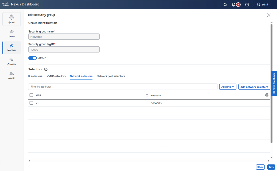
For the host-based segmentation, an IP selector that matches 192.168.1.21/32 can be created, as well as allocated SG Tag 10001. This will allow us to create a specific policy for routed traffic, and the bridged traffic will still be allowed because of the Network match statement matching the MAC address to SGT 10000 and the IP address to 10001.
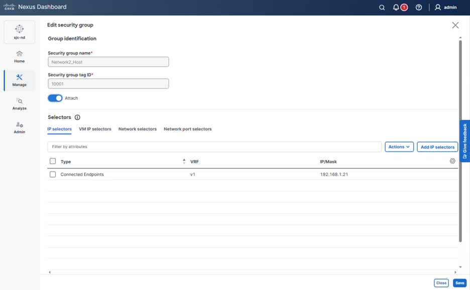
If the VRF is operating in enforced deny mode, then security associations can be made to allow the specific source and destination security groups to communicate using specific contracts.
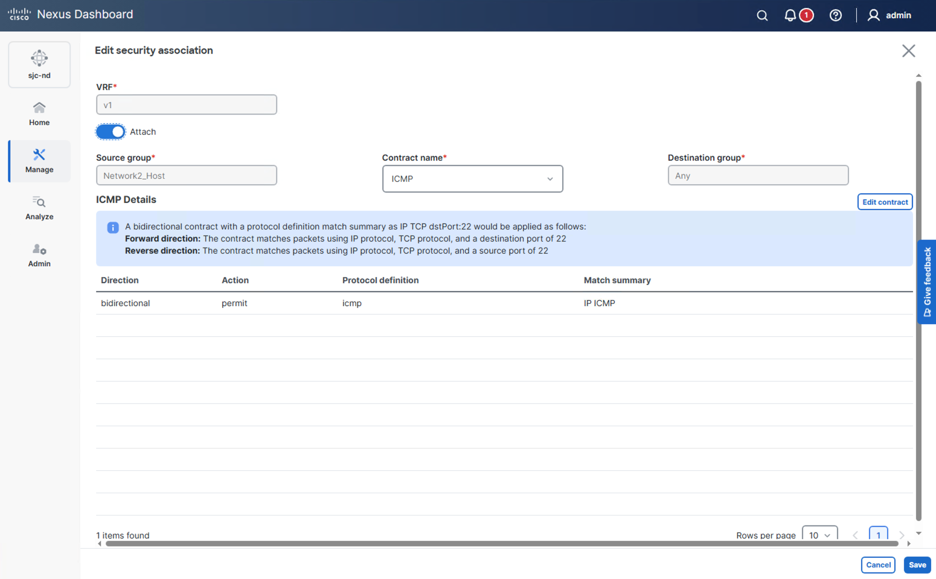
This will result in the following example CLI that will get pushed to all leafs and the border gateway within the NX-OS fabric:
class-map type security match-any icmp
description Match ICMP (auto generated)
match ip icmp
security-group 10000 name Network2
match vlan 201
policy-map type security ICMP_icmp
class icmp
permit
security-group 10001 name Network2_Host
match connected-endpoints vrf v1 ipv4 192.168.1.21/32
vrf context v1
security enforce tag 10669 default permit
exit
configure terminal
configure dual-stage
vrf context v1
security contract source 10001 destination any policy ICMP_icmp
commit
On the ACI fabric, there is an additional setting under the ESG: “Set Normalized pcTag.” This configuration will create a translation between remotely learned EVPN endpoints that have an SG Tag set, to the pcTag of the ESG for policy enforcement. For ESG2, the normalized pcTag is set to 10000 to match all remote devices in Network2 to ESG2.
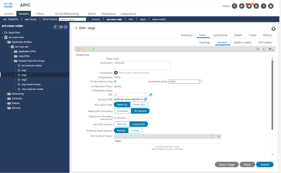
For host 192.168.1.21, which has been micro-segmented into a separate security group, a new ESG is created to match the host IP address, an normalize the SGTag 10001.
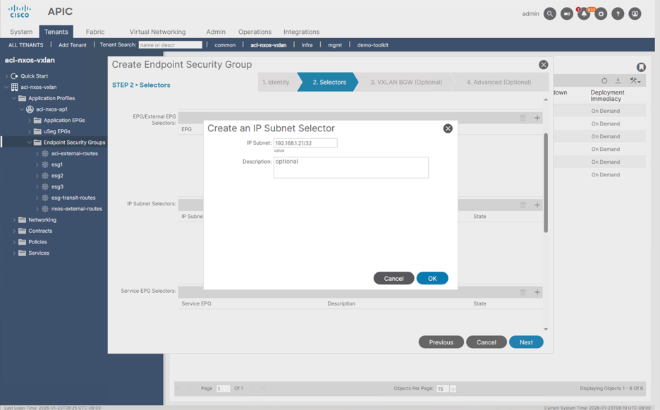
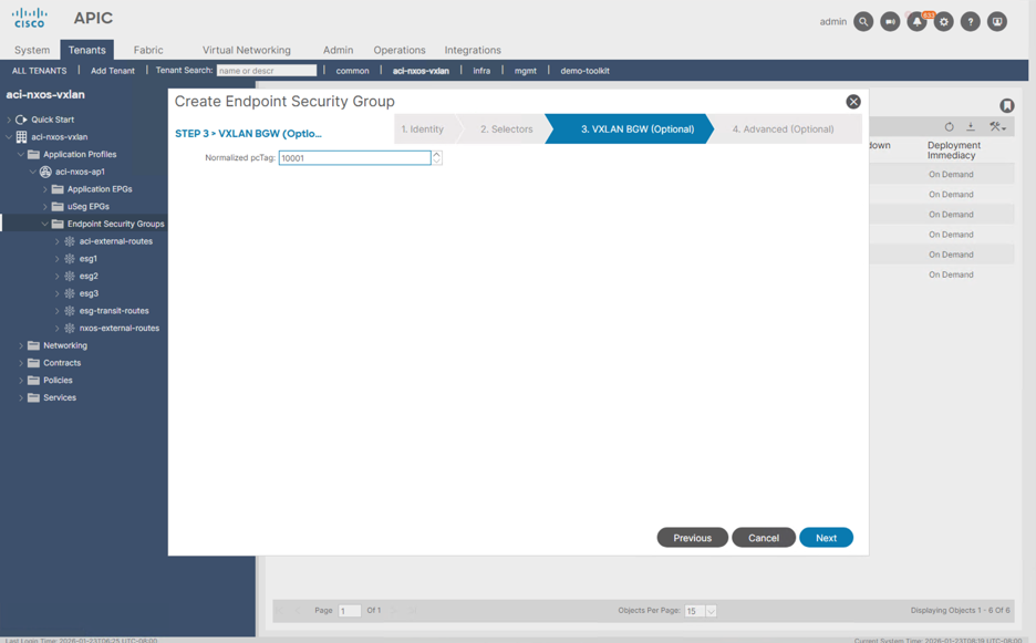
Once a contract is added between esg3 and esg2-host, then 192.168.2.10 will be able to establish connectivity to 192.168.1.21 using policy enforcement at both ends with the specific contracts.
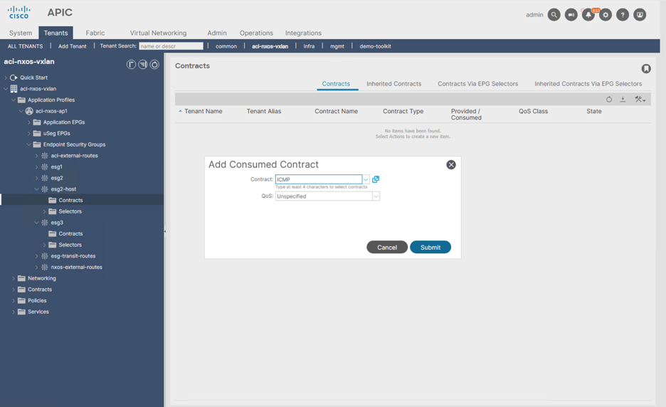
For verification purposes, we can check the BGP control plane to see if the remote L3 entries for both devices in Network2, as well as the micro-segmented host 192.168.1.21 are learned on each border gateway with the respective PCtag.
ACI Border Gateway (Both Pods):
aci-bgw1# show bgp l2vpn evpn 192.168.1.20 vrf overlay-1
Route Distinguisher: 1:48496609 (L2VNI 14942177)
BGP routing table entry for [2]:[0]:[0]:[48]:[0050.569c.c370]:[32]:[192.168.1.20]/272, version 1370 dest ptr 0x9c278dec
Paths: (1 available, best #1)
Flags: (0x0000000000000212 0000000000) on xmit-list, is in rib/evpn, is not in HW
Multipath: eBGP iBGP
Advertised path-id 1
Path type (0x908e1824): external 0xc0000028 0x400 ref 0 adv path ref 1, path is valid, is best path, remote nh not installed, in rib
Imported from (0x9092e730) 65002:201:[2]:[0]:[0]:[48]:[0050.569c.c370]:[32]:[192.168.1.20]/144
AS-Path: 65002 , path sourced external to AS
202.202.202.202 (metric 0) from 10.2.0.3 (10.2.0.3)
Origin IGP, MED 2000, localpref 100, weight 0 tag 4294966000, propagate 0, floating svi 0, tunnel resolved 0
Received label 201 100
Extcommunity:
RT:65100:100
RT:65100:201
SOO:65100:1291845613
COST:pre-bestpath:170:1610612736
ENCAP:8
PCTAG:00:0:0:10938
0x310:03100000:0000fdea
Router MAC:0200.caca.caca
Path-id 1 advertised to peers:
130.13.0.224
Route Distinguisher: 65002:201
BGP routing table entry for [2]:[0]:[0]:[48]:[0050.569c.c370]:[32]:[192.168.1.20]/272, version 1342 dest ptr 0x9c27794e
Paths: (1 available, best #1)
Flags: (0x0000000000000202 0000000000) on xmit-list, is not in rib/evpn, is not in HW, is locked
Multipath: eBGP iBGP
Advertised path-id 1
Path type (0x9092e730): external 0x40000028 0x4002000 ref 2 adv path ref 1, path is valid, is best path, remote nh not installed
Imported to 2 destination(s)
AS-Path: 65002 , path sourced external to AS
202.202.202.202 (metric 0) from 10.2.0.3 (10.2.0.3)
Origin IGP, MED 2000, localpref 100, weight 0 tag 4294966000, propagate 0, floating svi 0, tunnel resolved 0
Received label 201 100
Extcommunity:
RT:65100:100
RT:65100:201
SOO:65100:1291845613
COST:pre-bestpath:170:1610612736
ENCAP:8
PCTAG:00:0:0:10000
0x310:03100000:0000fdea
Router MAC:0200.caca.caca
Path-id 1 not advertised to any peer
aci-bgw1# show bgp l2vpn evpn 192.168.1.21 vrf overlay-1
Route Distinguisher: 1:48496609 (L2VNI 14942177)
BGP routing table entry for [2]:[0]:[0]:[48]:[0050.569c.9fc2]:[32]:[192.168.1.21]/272, version 1369 dest ptr 0x9c27772c
Paths: (1 available, best #1)
Flags: (0x0000000000000212 0000000000) on xmit-list, is in rib/evpn, is not in HW
Multipath: eBGP iBGP
Advertised path-id 1
Path type (0x908e14c4): external 0xc0000028 0x400 ref 0 adv path ref 1, path is valid, is best path, remote nh not installed, in rib
Imported from (0x9092ea70) 65002:201:[2]:[0]:[0]:[48]:[0050.569c.9fc2]:[32]:[192.168.1.21]/144
AS-Path: 65002 , path sourced external to AS
202.202.202.202 (metric 0) from 10.2.0.3 (10.2.0.3)
Origin IGP, MED 2000, localpref 100, weight 0 tag 4294966000, propagate 0, floating svi 0, tunnel resolved 0
Received label 201 100
Extcommunity:
RT:65100:100
RT:65100:201
SOO:65100:1291845613
COST:pre-bestpath:170:1610612736
ENCAP:8
PCTAG:00:0:0:17
0x310:03100000:0000fdea
Router MAC:0200.caca.caca
Path-id 1 advertised to peers:
130.13.0.224
Route Distinguisher: 65002:201
BGP routing table entry for [2]:[0]:[0]:[48]:[0050.569c.9fc2]:[32]:[192.168.1.21]/272, version 1344 dest ptr 0x9c278b14
Paths: (1 available, best #1)
Flags: (0x0000000000000202 0000000000) on xmit-list, is not in rib/evpn, is not in HW, is locked
Multipath: eBGP iBGP
Advertised path-id 1
Path type (0x9092ea70): external 0x40000028 0x4002000 ref 2 adv path ref 1, path is valid, is best path, remote nh not installed
Imported to 2 destination(s)
AS-Path: 65002 , path sourced external to AS
202.202.202.202 (metric 0) from 10.2.0.3 (10.2.0.3)
Origin IGP, MED 2000, localpref 100, weight 0 tag 4294966000, propagate 0, floating svi 0, tunnel resolved 0
Received label 201 100
Extcommunity:
RT:65100:100
RT:65100:201
SOO:65100:1291845613
COST:pre-bestpath:170:1610612736
ENCAP:8
PCTAG:00:0:0:10001
0x310:03100000:0000fdea
Router MAC:0200.caca.caca
Path-id 1 not advertised to any peer
● Cisco Nexus One Architecture White Paper
● Deploying and Verifying Cisco Nexus One Fabric Connectivity and Policy between ACI Fabrics