Securing Data Centers with Microsegmentation using VXLAN GPO
Available Languages
Bias-Free Language
The documentation set for this product strives to use bias-free language. For the purposes of this documentation set, bias-free is defined as language that does not imply discrimination based on age, disability, gender, racial identity, ethnic identity, sexual orientation, socioeconomic status, and intersectionality. Exceptions may be present in the documentation due to language that is hardcoded in the user interfaces of the product software, language used based on RFP documentation, or language that is used by a referenced third-party product. Learn more about how Cisco is using Inclusive Language.
- US/Canada 800-553-2447
- Worldwide Support Phone Numbers
- All Tools
 Feedback
 Feedback
Support on Nexus 9000 Switches
Security Group Routing Template
Order of Precedence with SGT Selectors
SGT Derivation and Policy Enforcement
ARP Suppression and Punting of Traffic to the CPU
East-West Enforcement in Single Site
East-West Enforcement in Multi-Site
North-South Policy Enforcement
Use-Cases and Configuration Examples
Policy Enforcement for East-West
Policy Enforcement for North-South
Automation using Nexus Dashboard
Data Centers are built to host applications and services and plays a pivotal role in an organization’s success. Therefore, securing the endpoints and the resources in a Data Center become very crucial.
In traditional Data Center environments, the application/workload security is often implemented at the perimeter or the north-south boundary. This is often implemented using perimeter firewalls and other security inspection solutions. However, this approach is not very effective against the advanced nature of attacks of late, as the attack surface spans the entire Data Center, including the east-west/north-south flows.
Perimeter security solutions deployed at the Data Center boundary are often limited to north-south flows and due to scalability challenges cannot be extended to east-west flows.
Due to scalability challenges and cost involved, perimeter security services cannot scale to east-west flows; hence segmentation at the fabric level is needed. In simple words, segmentation allows dividing the network into smaller segments by creating security zones and controlling the communication between these zones. Segmentation is not new to networking, traditionally it was achieved through the combination of Private VLANs (PVLANs) and ACLs.
While a PVLAN based solution was used to provide segmentation within the same broadcast domain by using constructs like Primary and Secondary (Isolated and Community) VLANs, segmentation within a broadcast domain is often referred to as Micro Segmentation. On the other hand, ACLs were used to permit or deny communication between the two broadcast domains.
Due to increased adoption of virtualization and change in traffic flow pattern, Data Centers evolved to fabrics that offer better flexibility and scalability to meet the demand of businesses. VXLAN EVPN based fabrics are the de-facto standard for building such modern Data Center fabrics. Although PVLANs and ACLs are supported on VXLAN fabrics, there was a need of a segmentation solution that was more scalable and robust in nature. This has led to the introduction of VXLAN GPO (Group Policy Option).
The VXLAN GPO solution allows classifying the connected endpoints and resources external to the fabric into segments, which are referred to as Security Groups (SGs). Contracts (SGACLs) can then be defined and applied between the SGs, controlling who can talk to who over the fabric.
VXLAN Security Groups (SGs) and Security Group ACLs (SGACLs) constructs provide an effective solution for NX-OS standalone platforms to implement security posture across the fabric.
Multiple use cases can be addressed with the deployment of NX-OS VXLAN GPO technologies, all revolving around two main constructs: network segmentation and traffic redirection to service functions (service chaining).
VXLAN GPO allows administrators to define policies for network segmentation, which enable them to create smaller, isolated segments within a network. This offers administrators better control of the traffic over the network, ensuring that communication between the services and endpoints is allowed only when they are needed. Network segmentation policies can be either unidirectional or bidirectional.
With VXLAN GPO based segmentation, organizations can define application-specific policies that specify how the application workloads communicate regardless of where these applications reside within the fabric.
Note: The deployment of GPO per se does not offer specific “application discovery mapping” capabilities. The assumption is that the specific policies that need to be enforced between different security groups are known by the user.
VXLAN GPO is not just limited to the support of segmentation, but it can also be used to simplify the insertion of network services for north-south or east-west traffic flow paths based on specific policy criteria. By defining service chains and applying them to specific groups of network resources, administrators can ensure that traffic is routed through the appropriate network functions, such as firewalls, load balancers, or intrusion detection systems.
Below are some specific examples of use cases that can be fulfilled with the deployment of NX-OS GPO functionalities. This is obviously not an exhaustive list and many other examples can be found in real life deployments.
VRF as a Security Zone
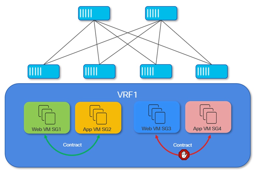
In this scenario, the primary objective is to group all fabric resources (both internal and external) that are connected to a specific VRF routing domain and classified into a single security zone. This approach allows seamless communication between entities within the same VRF, while maintaining strict logical isolation from other VRF routing domains in the data center fabric.
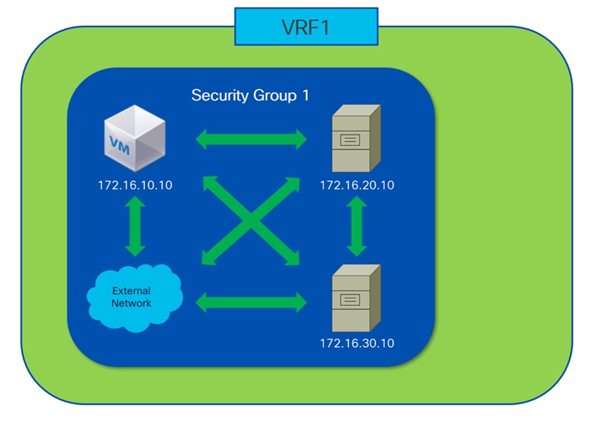
Traditionally, VRFs (Virtual Routing and Forwarding instances) are used to achieve this type of logical separation, enabling multiple isolated routing domains to coexist within the same physical infrastructure. As shown in Figure 3, this method alone is sufficient to ensure that traffic remains isolated between VRFs, allowing unrestricted communication only within each individual VRF.
However, introducing Group Policy Option (GPO) functionality adds an extra layer of flexibility and control. While VRFs provide robust domain-level isolation, GPOs allow administrators to dynamically segment and classify resources within a VRF, based on evolving operational or security requirements. This capability becomes especially valuable if, for example, there is a need to isolate or quarantine specific endpoints or workloads without impacting the rest of the resources within the same VRF.
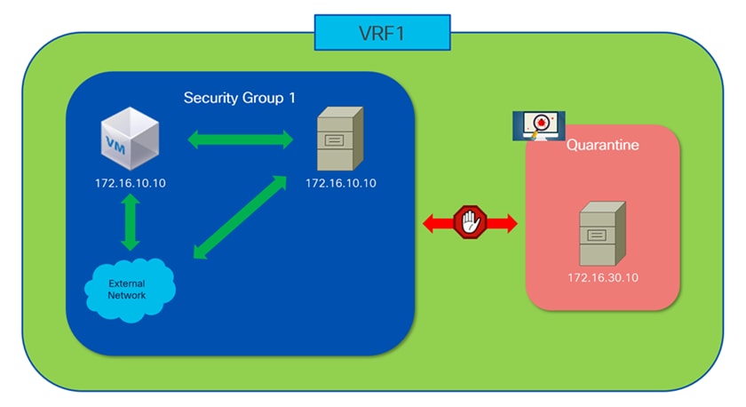
Figure 4 illustrates such a use case: if a particular endpoint's security posture is compromised, perhaps due to a detected vulnerability or malicious activity, the affected endpoint can be dynamically reassigned to a separate security group within the same VRF. By quarantining the impacted endpoints in this manner, administrators can take corrective action, such as sanitizing or remediating the device, while preventing any potential threat from spreading to other resources in the VRF. This granular level of segmentation enhances the overall security posture of the fabric, offering administrators precise control over resource access and communication, and providing rapid response mechanisms to emerging security threats.
Subnet as a Security Zone
Enforcing security policies between different subnets within the same VRF routing domain is a common requirement in modern data center environments. Traditionally, this need has been addressed by deploying Access Control Lists (ACLs) on routers or switches, or more frequently, by positioning the default gateway for each subnet on an external firewall appliance. This latter approach ensures that all inter-subnet traffic is subject to inspection and policy enforcement by the firewall before reaching its destination.
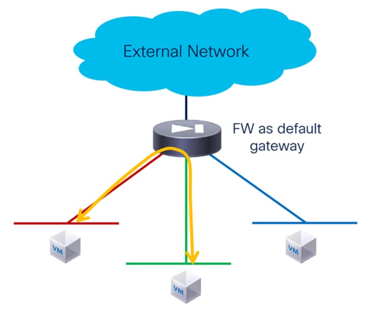
While the architecture illustrated in Figure 5 achieves the necessary security controls, it comes with significant trade-offs. Specifically, by directing all inter-subnet communications through a centralized firewall, the model introduces a potential performance bottleneck. Even with the availability of high-throughput, next-generation firewalls in the market, the volume of East-West traffic within the data center can quickly exceed the capacity of these devices. This can result in increased latency, diminished application performance, and the eventual need for costly hardware upgrades or replacements as traffic grows.
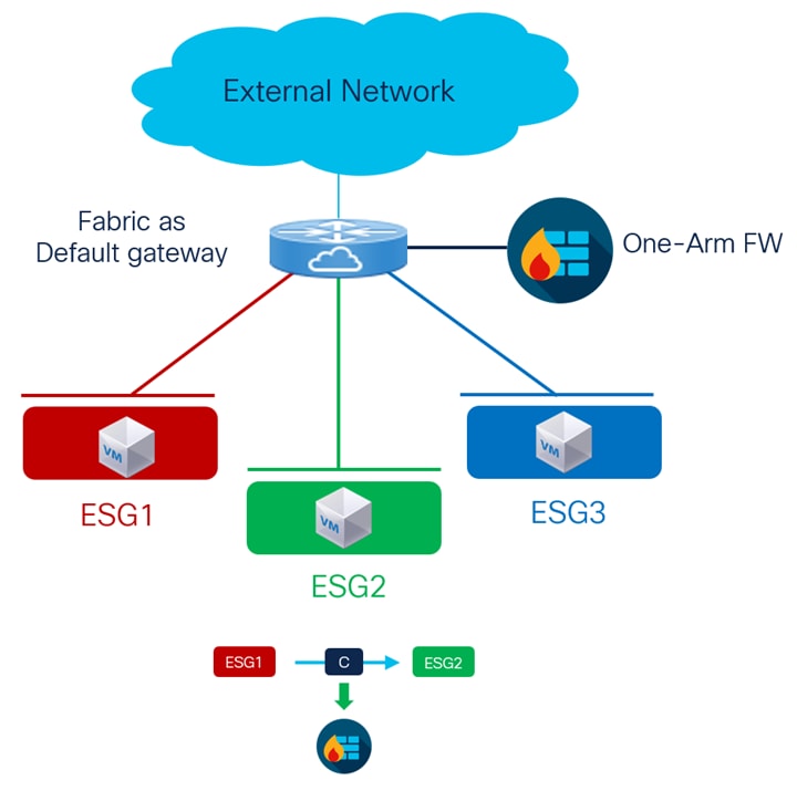
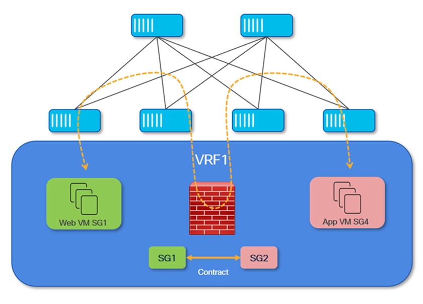
The introduction of Group Policy Option (GPO) technology provides a much more efficient and scalable alternative. As depicted in Figure 6, administrators can assign each subnet to its own security group, allowing stateless security policies (functionally similar to traditional ACLs) to be enforced natively and efficiently on the network devices themselves. This eliminates the need to hairpin all traffic through an external firewall, greatly improving both scalability and network performance while still maintaining logical isolation between resources in different subnets.
Furthermore, GPO enhances flexibility by supporting service redirection. This means that only specific inter-subnet traffic flows requiring advanced security such as stateful inspection or application-level filtering can be selectively steered to a firewall or other security service. This targeted approach ensures optimal use of firewall resources, dedicating them solely to the traffic that truly requires deep inspection, while allowing the majority of routine communications to be processed at line rate within the fabric
Application as a Security Zone
As highlighted earlier, the deployment of Group Policy Option (GPO) is not intended to replace advanced application discovery or dependency mapping tools, which are designed to analyze and determine the precise communication patterns and requirements among the various components of complex, modern applications. Rather, GPO serves as a powerful framework for implementing security and segmentation policies once application components and their interactions have been identified.
In practice, it is often feasible for administrators to recognize and categorize the different elements that make up each application. By grouping these related components into distinct security groups, organizations can achieve several significant advantages, as illustrated in Figure 7 below:
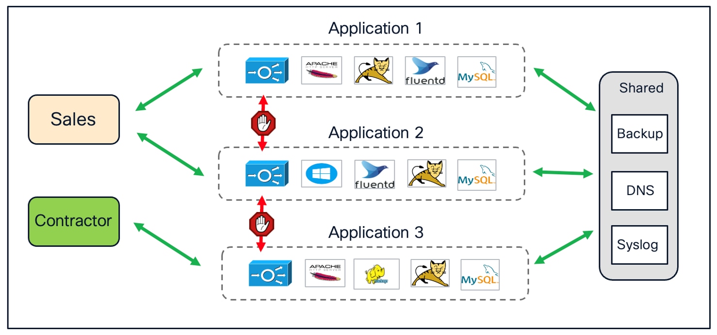
First, this approach enables logical isolation between different applications, preventing unintended or unauthorized interactions across application boundaries. Each application operates within its own secure zone, reducing the risk of lateral movement in the event of a compromise. Meanwhile, this segmentation strategy still allows all applications to access shared infrastructure resources (such as backup servers, DNS, or Syslog services) by assigning these resources to a common security group with the appropriate access permissions.
Additionally, GPO makes it possible to implement user-based access controls. Different user groups can be granted access exclusively to the applications necessary for their roles, ensuring that sensitive applications remain protected and reducing the organization's overall attack surface. This not only enhances overall security but also simplifies compliance with regulatory and internal governance requirements.
Overall, while GPO does not automate the discovery of application dependencies, it provides a flexible and scalable means of enforcing logical boundaries between applications, managing shared resources, and tailoring user access, all of which contribute to a more secure and resilient data center environment.
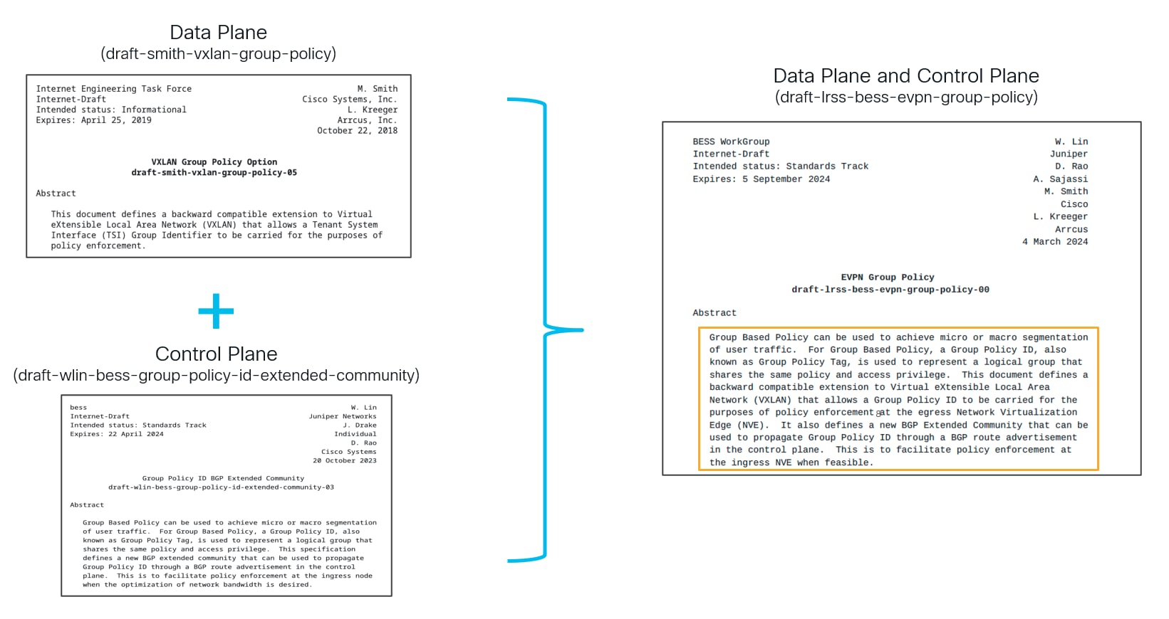
VXLAN GPO implementation on NX-OS is based on standard as per IETF RFC draft EVPN Group Policy (draft-lrss-bess-evpn-group-policy-00). EVPN Group Policy RFC draft defines Data Plane and Control Plane operations for VXLAN GPO which is a combination of two RFC drafts draft-smith-vxlan-group-policy and draft-wlin-bess-group-policy-id-extended-community defining Data Plane and Control Plane operations respectively.
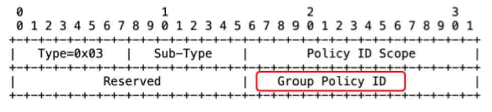
VXLAN GBP (Group Based Policy) is a backward-compatible extension to VXLAN and utilizes some of the reserved fields to carry GPO information:
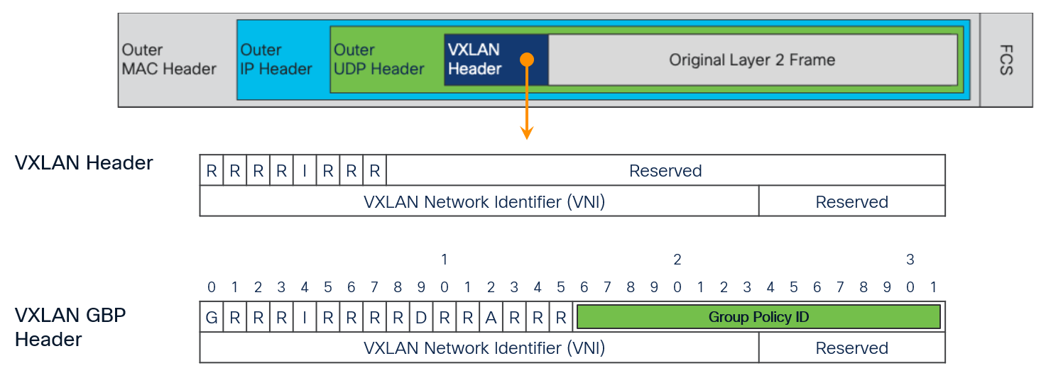
The following figure shows the fields used by GPO implementation.
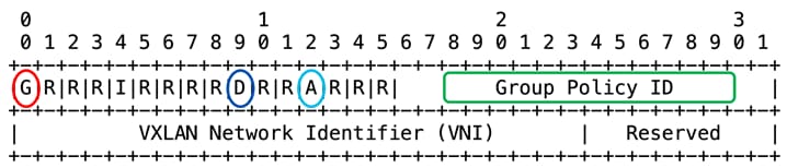
G Bit: Bit 0 of the initial word is defined as the G (Group Based Policy Extension) bit.
● G = 1 indicates that the source TSI Group membership is being carried within the Group Policy ID field as defined in this document.
● G = 0 indicates that the Group Policy ID is not being carried, and the G Bit MUST in that case be set to 0 as specified in [RFC7348].
D bit: Bit 9 of the initial word is defined as the Don't Learn bit. When set, this bit indicates that the egress VTEP MUST NOT learn the source address of the encapsulated frame. NX-OS implementation does not use this bit.
A Bit: Bit 12 of the initial word is defined as the A (Policy Applied) bit. This bit is only defined as the A bit when the G bit is set to 1.
● A = 1 indicates that the group policy has already been applied to this packet. Policies MUST NOT be applied by network devices when the A bit is set.
● A = 0 indicates that the group policy has not been applied to this packet. Group policies MUST be applied by network devices when the A bit is set to 0 and the destination Group has been determined. Network devices that apply the Group policy MUST set the A bit to 1 after the policy has been applied.
Group Policy ID: 16-bit identifier that indicates the source TSI (Topology Service Identifier) Group membership information within the VXLAN header.
The added value of enhancing the MP-BGP EVPN control plane to be able to carry security policy information will be extensively discussed in the following sections of this paper.
Support on Nexus 9000 Switches
VXLAN GPO feature was first introduced in the NX-OS 10.4(3)F release and has extended its capabilities and hardware support with the subsequent releases. The following table summarizes the GPO capabilities enabled in various NX-OS releases.
Table 1. VXLAN GPO feature support in NX-OS releases
| NX-OS Release |
Feature Detail |
Platforms |
Classification Criteria |
| 10.6(1)F |
New classification criteria, Segmentation support with L2 VLAN |
|
Port + VLAN
|
| 10.5(3)F |
GPO support with MPLS-SR handoff, New classification criteria |
|
Port VLAN mapping IP Prefix + Next-hop IP Prefix + Next-hop + Encap Type |
| 10.5(2)F |
New Platforms |
9300-FX/FX2/HX |
|
| 10.5(1)F |
GPO based Service Redirection, New platforms, New classification criteria |
Nexus 9408 |
VLAN Range
|
| 10.4(3)F |
GPO based Segmentation |
N9300-FX3/GX/GX2A/GX2B |
IPv4/IPv6 Connected Endpoints/Subnets IPv4/IPv6 External Networks VLAN |
The following table summarizes GPO scale supported on different Nexus 9000 platforms:
Table 2. VXLAN GPO support on Nexus 9000 series switches
| Platform |
ESG Selectors |
SGACLs |
| N9300-FX/FX3/GX/GX2B/HX |
8000 |
64000 |
| N9300-FX2/GX2A, Nexus 9408 |
8000 |
32000 |
Note: The scale numbers given in the table above are valid for each individual device. For more details, please refer to the NX-OS Verified Scalability Guide.
VXLAN GPO introduces new constructs for the provisioning and the operation of this functionality. This section describes those constructs in detail from an NX-OS perspective.
A Security Group (SG) is a logical entity (acts as a logical container) that contains a collection of network endpoints or external prefixes. The Endpoints connected to VXLAN fabric can be classified based on their IPv4/IPv6, MAC, Port, VLAN, VM attributes etc. On the other hand, external networks can be classified based on IPv4/IPv6 prefix information.
See VXLAN GPO Implementation on NX-OS section to decide which selector is available in a particular NX-OS release.
Usually, the endpoints and external networks that have the same traffic profile should be classified as part of the same SG.
Endpoints in the same SG can communicate without any contract while communication between the endpoints of different SGs is governed by SGACL contracts.
A security group may also contain the endpoints and prefixes from different VRFs. It is worth to be noted here that route leaking between the VRFs should be configured explicitly if the two endpoints of different VRFs are allowed to communicate (separation between security policy and network connectivity).
While creating the security groups, we must take into account that policy enforcement is currently supported between any two security groups (Inter-SG). Intra-SG policy enforcement (and intra-SG isolation) is on roadmap and would be supported in a future NX-OS release.
Security Group Tag
Each Security Group (SG) is assigned a unique 16-bit Security Group Tag -SGT (the previously introduced Group Policy ID). Security policies (contracts/SGACLs) are then defined to dictate who can talk to who over the fabric. When defining those SGACLs, SGTs of source and destination are used. The SGT of the source is referred to as S-SGT, whereas the SGT of the destination is referred to as D-SGT.
The 16-bit Group Policy ID field of the VXLAN GBP header is used to carry the SGT value, which provides SGT range of 0-65535. However, the SGT range 0-15 is reserved therefore only SGT values from 16 onwards can be assigned to the user defined SGs.
0-15 are the reserved SGTs which are used for different purposes, some of the reserved SGTs and their usage are mentioned below:
● SGT 0 – Also referred to as default tag, it is associated to any endpoint or subnet that has not been explicitly classified.
● SGT 1 – This tag is associated to the Type-5 EVPN advertisement generated for the directly connected networks on a VTEP (i.e. the endpoints’ subnets). SGT 1 plays an important role in the discovery of silent hosts in the fabric, as will be clarified later in this paper.
● SGT 15 – This tag is used in the scenario when there is a policy-unaware (non-GPO enabled) fabric part of a Multi-Site domain. Upon receiving EVPN routes from a policy-unaware fabric, the BGW of a policy-aware (GPO enabled) fabric automatically assigns SGT 15 to all the EVPN (Type 2 & 5) routes received from the policy-unaware site.
In addition, there is also a user-defined SGT associated to the VRF which is referred to as VRF tag and used to enforce the policy in various scenarios:
● When both source and destination endpoints are not explicitly classified (based on the configured selectors), the default SGT value is derived as both source and destination SGTs. Since policy can’t currently be enforced between two endpoints belonging to the same security group, the SGT value of one of the endpoints is swapped with VRF tag to enforce the default (permit or deny) action set for the VRF.
● Also in certain scenarios, the VRF Tag is used to create permit contracts for BUM traffic.
Every SG is defined as a name and an SGT value. SGT is a fabric-wide construct and exchanged with other VTEPs (Leaf nodes) hence it has to be unique in the fabric. When deploying multiple fabrics as part of the same VXLAN EVPN Multi-Site domain, the current assumption is that the SGT values are globally significant and homogeneously defined across all the fabrics.
With VXLAN GPO based segmentation, either of the following two approaches can be followed when it comes to classifying the endpoints and prefixes to security groups-
Network-Centric Approach
Sometimes referred to as “macro-segmentation” or simply “segmentation”. In this approach, classification criteria such as prefix routes or VLANs (L2VNIs) are used to classify one or more subnets/VLANs to the same SG.
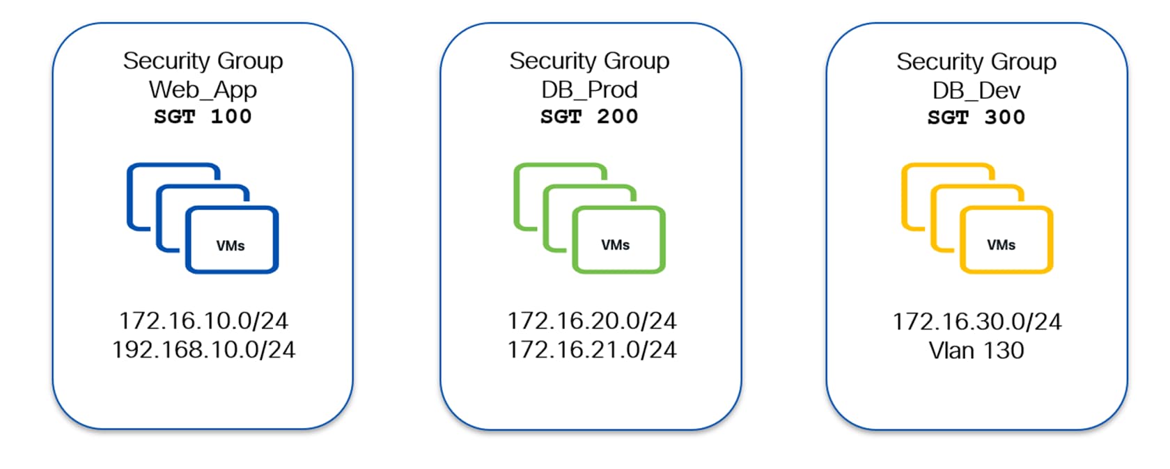
The following diagram shows an example of a network-centric approach. Here the classification is based on the endpoints’ network or VLAN (L2VNI) they connect to.
All the endpoints belonging to the subnets 172.16.10.0/24 & 192.168.10.0/24 are mapped to Web_App SG. Similarly, all the endpoints belonging to subnets 172.16.20.0/24 & 172.16.21.0/24 are mapped to DB_Prod SG and DB_Dev is mapping all the endpoints belonging to subnet 172.16.30.0/24 and VLAN 130.
Host-Centric Approach
Also referred to as “micro-segmentation”, it is usually adopted in scenarios where a more granular policy-enforcement is required. In this approach classification criteria such as host routes (/32) or port+VLAN are used, which allow classification based on the endpoint’s identity.
Since the endpoints are classified based on their own identities, mapping of two endpoints belonging to same subnet/VLAN to different SGs is possible.
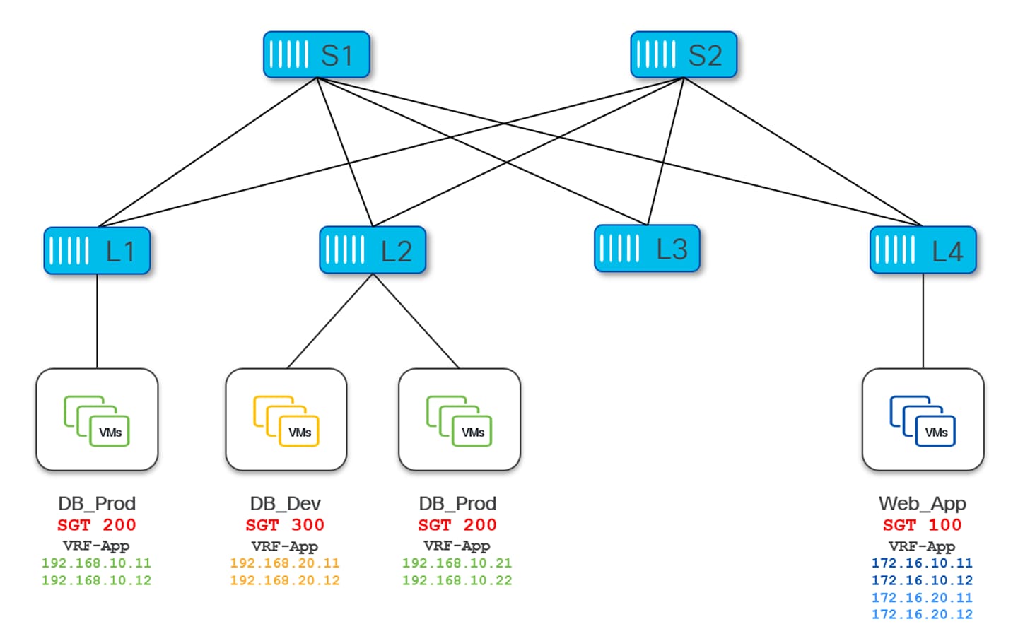
The following diagram shows an example of a host-centric approach with three security groups Web_App (SGT 100), DB_Prod (SGT 200) and DB_Dev (SGT 300). Specific endpoints are only classified and mapped to their respective security groups.
Endpoints 172.16.10.11-12 & 192.168.10.11-12 are mapped to the Web_App SG. Endpoints 172.16.10.21-22 & 192.168.20.21-22 are mapped to DB_Prod and endpoints 172.16.10.31-32 are mapped to DB_Dev –
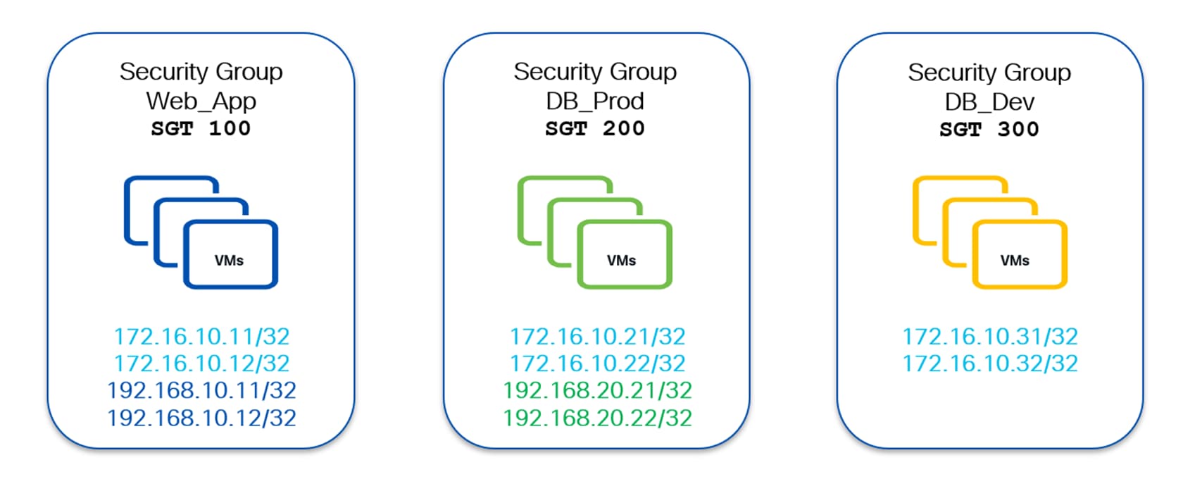
It is worth noting here that endpoints belonging to the same subnet (172.16.10.0/24) are classified to different SGs.
Note: As it should be apparent, the deployment of network centric or host centric solely depends on the way classification rules are defined. As a consequence, it is very much possible to use a mix of both approaches within the same VXLAN fabric, if needed.
The traffic selector construct of NX-OS adds granularity and provides full control to users for VXLAN GPO based policy enforcement. Using traffic selectors, one can define the traffic of interest between two SGs for which a security policy should be enforced.
Traffic selectors offer various options such as Ether-Type, L3-L4 protocols and L4 Src/Dst ports and other parameters for defining the traffic flows that must be subject to the policy enforcement.
Security contracts or SGACLs (Security Group Access Control Lists) formulate the security policy over the network that defines if two endpoints are allowed to talk to each other or not.
A Security Contract glues the previously defined GPO constructs together. First, endpoints/networks are classified into different Security Groups (SGs) that are identified by their unique SGTs. Then, a traffic selector is used to identify the traffic of interest between the two SGs. Finally, security contracts (SGACLs) are used to ensure that specific traffic flows between two SGs are permitted or denied (for the segmentation use-case), or if it should be redirected to a service function or a chain of service functions (for the service chaining use case).
When applying a security contract between SGs, it is required to always identify a source and a destination SG. This is critical since security contracts can either be bidirectional or unidirectional in nature. Bidirectional means that the applied contract would allow traffic in both directions (from source to destination and from destination back to source SG), so that full communication can be established. On the other hand, unidirectional contracts apply to the traffic in only one direction (from source to destination or from destination to source).
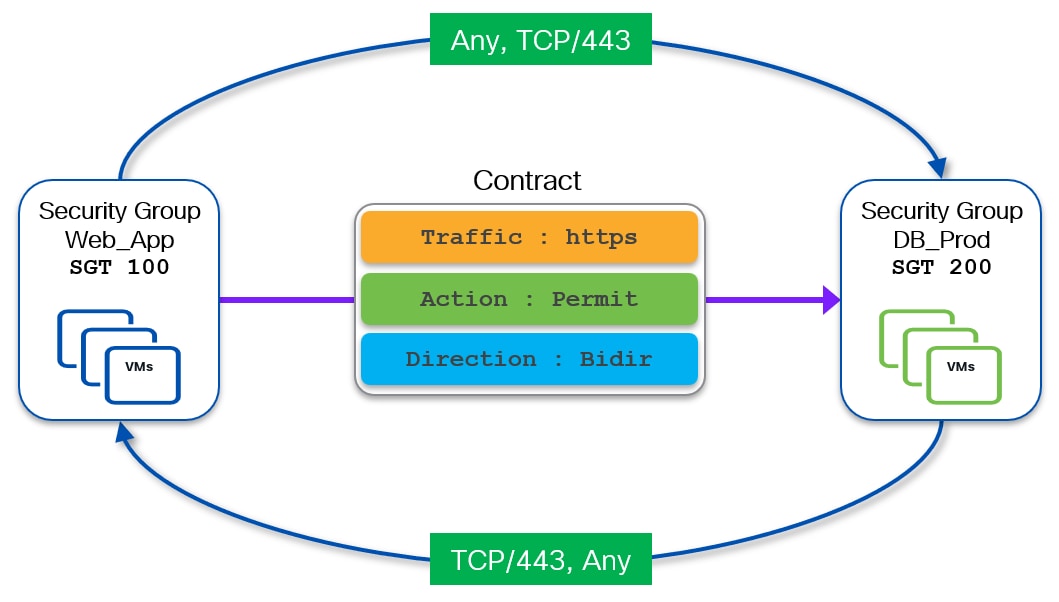
The following diagram shows an example of a bidirectional contract permitting HTTPs (TCP port 443) traffic between source Web_App (SGT 100) security group and destination DB_Prod (SGT 200) security group.
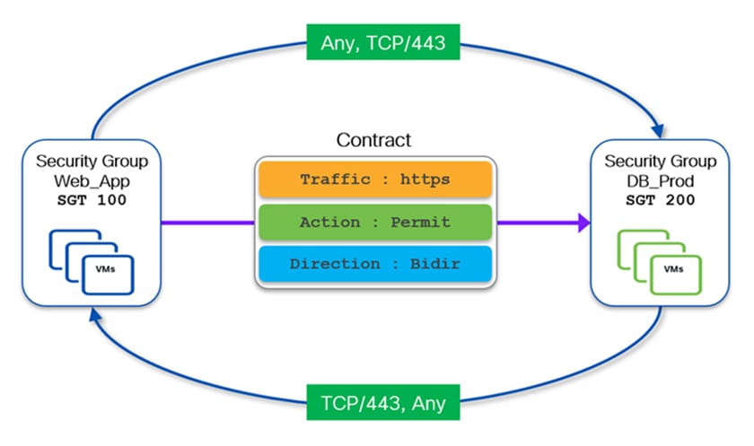
The definition of a bidirectional contract is required to establish two-way communication between entities (endpoints or external resources) belonging to the two security groups. Whenever a bidirectional contract is defined, NX-OS automatically creates the required return rule.
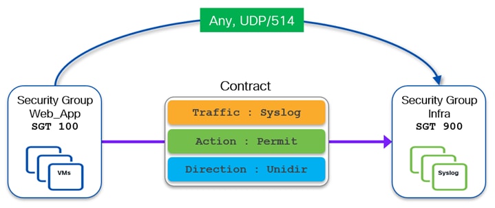
If one-way communication enforcement is preferred, a unidirectional contract can be created. The following diagram shows an example of a unidirectional contract allowing the endpoints in source security group Web_App sending Syslog messages (UDP dest port 514) to the Syslog servers in destination security group Infra. Since it is a unidirectional contract, traffic in the reverse direction is not permitted.
Note: Two separate unidirectional contracts could be defined also to allow the two-way communication show in the previous Figure 13. The first contract would allow traffic originated from any port and destined to TCP port 443 between Web_App and DB_Prod SGs. The second contract would instead allow the return flow originated from TCP port 443 and destined to any port between DB_Prod and Web_App SGs.
The previous examples show the use of permit contracts, which are generally used when a VRF is configured in enforced-deny mode (more on this in the following section). Since no communication between SGs is allowed by default, permit contracts are required to open specific communication between the SGs.
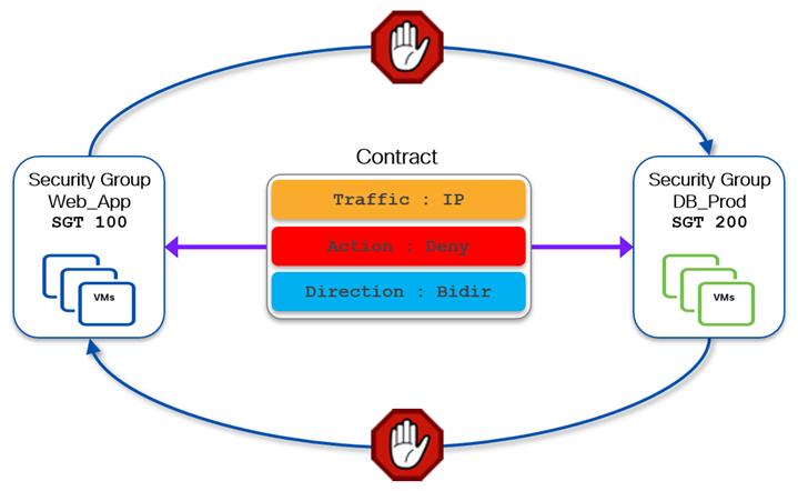
When a VRF is instead configured in enforced-permit mode, communication between any two SGs is allowed by default. Therefore, contracts can be defined to explicitly denying the communication between any two SGs. The following diagram shows a bidirectional deny contract to block all IP traffic between Web_App and DB_Dev security groups.
Unlike legacy solutions such as PVLAN, which provides enforcement only within a broadcast domain, VXLAN GPO allows to perform enforcement at the VRF (and even inter-VRF) level. This means that a GPO based solution can provide segmentation between endpoints part of the same broadcast domain, as well as between multiple broadcast domains part of the same VRF (or even part of different VRFs). This is important to ensure full separation between the definition of security policies and the provisioning of network connectivity, which are tasks often performed by different persona.
By default, a newly defined Tenant VRF has enforcement set to Unenforced, which means no security policies are enforced for that VRF even if classification criteria and SGACLs between the SGs are configured.
To enable policy enforcement, the VRF mode needs to be changed from Unenforced to Enforced. On NX-OS when you configure the VRF in enforced mode, you can choose the default behavior to be either Default-Deny or Default-Permit.
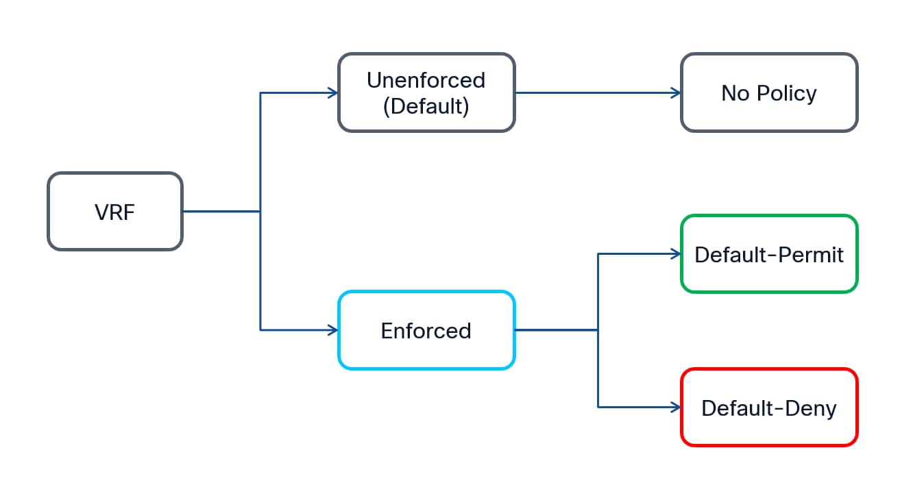
Default-Permit: Also referred to as “black-list model”. All unicast traffic flows between security groups are allowed unless explicitly denied by a contract. Since all the communication is allowed in this model, the contracts can be defined and used to deny the traffic between any two security groups.
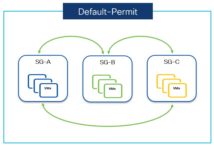
The above diagram shows VRF Default-permit mode in action, where security groups SG-A, SG-B and SG-C can communicate to each other without any contract.
Default-Deny - Also referred to as “white-list model”. All the unicast traffic flows are denied unless explicitly permitted by a contract. This mode should be used when Zero Trust model needs to be implemented.
For any communication to take place over the fabric it has to be explicitly allowed by a contract. Since no communication is allowed in this model to begin with, the contracts must be defined to permit the traffic between any two security groups.
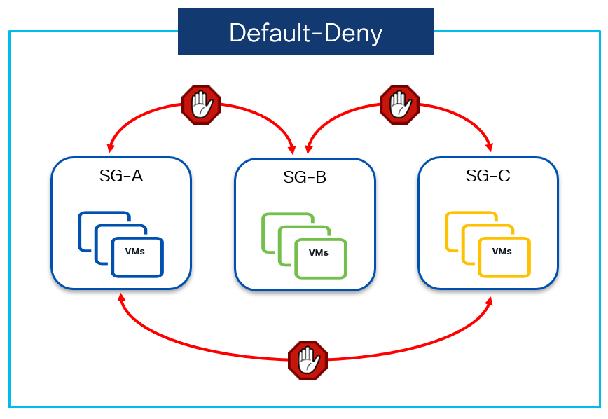
The above diagram shows the VRF’s Default-deny mode in action, where security groups SG-A, SG-B and SG-C can’t communicate to each other. If communication needs to be opened then a permit contract is required. Communication between the resources belonging to the same group is instead always permitted.
Note: As of NX-OS release 10.5(3), it is not supported to apply contracts between entities part of the same SG, nor to enforce intra-SG isolation. Those use cases will be introduced in a future NX-OS release.
When a GPO based policy enforcement needs to be enabled in a brownfield environment, it is always a good practice to begin by setting the VRF in default-permit mode and then start creating the policies (preferably with log option for verification purpose), so to continue permitting communications between the SGs. Since the VRF is in default-permit mode it will not impact any existing communication irrespective of the presence of the contract and with the help of the logs it can also be ensured that whatever policies have been defined are working as expected.
Once all the policies have been defined and verified to be working as expected, it is possible to change the VRF to restrictive mode by flipping the VRF’s enforced mode to default-deny with the help of a single CLI command. This will result in communication to take place as per the defined permit contracts, while all the rest of the communication is denied.
By using the above approach, GPO based policy enforcement can be implemented in a production VXLAN EVPN fabric without a fear of breaking something and minimizing the chances of downtime.
Note: When the log keyword is used with associated to a specific policy, matching traffic can be seen using the CLI command show logging ip access-list cache.
Security Group Routing Template
SGTs are programmed in the forwarding table along with respective EVPN routes. While the SGACLs (contracts) are programmed in the Policy TCAM which is dedicated for SGACLs only. It is worth to mention here that, since a dedicated TCAM resource is used for SGACLs, it does not compromise the scale for ACL/NAT/QoS etc rules that are programmed in a separate TCAM space, usually referred to as Classification TCAM. This can undoubtedly be called out as one of the main differentiators for GPO based policy enforcement, which makes it much more scalable compared to a PVLAN/ACL based segmentation approach.
Hardware forwarding table (FIB) on Cloud Scale family of Nexus 9000 series switches is made up of a collection of smaller units called Flex tiles. NX-OS offers various pre-built Routing-Templates to partition the forwarding table (Flex tiles) depending on the use-case. Security Group Routing Template on NX-OS has been introduced to carve out the forwarding flex tiles to program SGTs and SGACLs on Nexus 9000 switches. The enablement of such template is hence the first step required on Nexus 9000 platforms to then be able to provision the security group configuration.
Note: After enabling the Security group routing template, it is mandatory to reload the device for the carving out of the forwarding flex tile to take effect.
The following sections provide more details on the specifics of the NX-OS implementation for VXLAN GPO functionalities, clarifying what are the available selector types, what is the order of precedence between different selector types, how SGT values are derived on the fabric leaf nodes and the requirement for the enablement of ARP suppression in conjunction with GPO deployments.
ESG selectors offers a wide range of options for classification. Depending on whether a selector uses L2 or L3 information for classification, ESG selectors can be categorized as either Layer-2 or Layer-3.
The following ESG selectors are available in NX-OS 10.5(3) release, more selectors would be added in upcoming NX-OS releases.
Layer-2 ESG Selectors – used to classify endpoints based on their Layer-2 attributes:
● VLAN
● VLAN + MAC address
Layer-3 ESG Selectors – used to classify endpoints/networks based on their Layer-3 attributes:
● For internal endpoints and networks
◦ IPv4/IPv6 Host Route
◦ IPv4/IPv6 Subnet prefixes
● For external networks
◦ IPv4/IPv6 Prefix Routes
When a Layer-3 (IP based) ESG selector is used for the classification of endpoints, the endpoint needs to be learned by the Adjacency Manager (AM) component on NX-OS. AM is responsible for maintaining IP to MAC binding for directly connected hosts. In the current implementation, this requires the creation of an ARP entry for each specific endpoint and that mandates the instantiation of an SVI for each specific subnet. Without SVI being present on the local VTEP, ARP table are not populated and SGTs can’t be associated to the IP address of local endpoints.
For example, in the specific use case where the default gateway function is deployed on a Layer 3 device external to the fabric (external router or firewall), the use of Layer-3 selectors is possible only when defining an SVI for each specific endpoint subnet on the VTEP. Obviously, this SVI should get assigned a different IP address from the one used on the external device as default gateway for the endpoints.
Order of Precedence with SGT Selectors
On NX-OS, SGTs are derived as per the following rules:
Internal Endpoints
For internal endpoints, SGTs are derived from the SGT selectors configured on the local VTEP (where the endpoints are directly connected) in the order mentioned below:
1. IP SGT is derived from the matching Layer-3 selector configured
If no L3 selector is configured, SGT is derived using L2 matching selector
2. MAC SGT is derived from the matching Layer-2 selector configured
If there is no L2 selector configured, MAC SGT is not derived
The following flow chart shows how the SGTs are derived for a given endpoint:
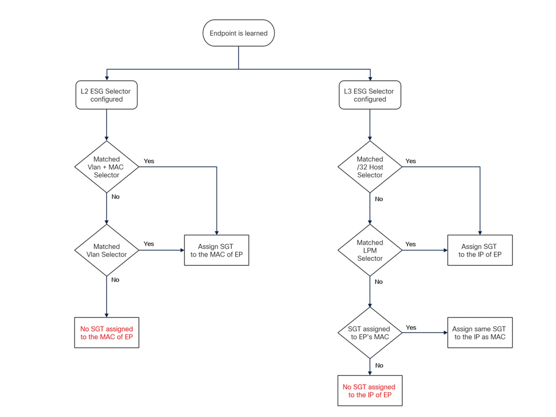
Note: LPM (Longest Prefix Match) rule is followed with L3 selectors. For L2 selectors, VLAN + MAC will take precedence over VLAN selector. If no SGT is derived for an endpoint, it will get the default tag SGT 0.
External Networks
For external networks, SGTs are derived from the SGT selectors configured on the respective Border VTEPs (where the external prefixes are learned via BGP/OSPF/Static routes)
If the EVPN update is received from a policy-unaware VTEP or site, upon receiving the update BGW of the policy-aware site assigns SGT 15 (policy-unaware SGT).
Once the SGT is associated with an endpoint/ internal network/external network, it is propagated via EVPN control plane update by using the respective Type-2 or Type-5 routes. The receiving VTEP uses the SGT that came along with the EVPN update, it cannot modify or overwrite it.
SGT Derivation and Policy Enforcement
As shown in Figure 19, it is possible to have two different SGTs assigned to the same endpoint, one associated to its MAC addresses and other associated to its IP address.
When Layer-2 ESG selectors are used, the same defined SGT value is associated to the MAC and the IP of the endpoint, if an ARP entry binding MAC and IP exists on the local VTEP and there is no Layer-3 selector match found for the endpoint’s IP.
The following example highlights the definition of a VLAN based L2 selector and how to verify that the same SGT gets assigned to the MAC and the IP of a specific endpoint (IP-172.16.10.11, MAC 0050:7216:1011)
security-group 110 name SG_110
match vlan 2300
Leaf1# show l2route mac topology 2300
<snip>
Topology Mac Address Prod Flags Seq No Next-Hops
----------- -------------- ------ ------------------ ---------- ---------------------------
2300 0050.7216.1011 Local L, 0 Eth1/1 (SGT - MAC:110)
Leaf1# show l2route mac-ip topology 2300
<snip>
Topology Mac Address Host IP Prod Flags Seq No Next-Hops
----------- -------------- ------------------------------ ------ --------------------------
2300 0050.7216.1011 172.16.10.11 HMM L, 0 Vlan2300 (SGT - IP:110)
When Layer-3 ESG selectors are used, the defined SGT tag is only associated to the IP of the endpoint. No SGT is associated to the MAC of the endpoint, and this is purposely done to address the scenario where the same MAC is mapped to more than one IP.
The following example shows the definition of a Layer-3 selector and how the SGT value is only associated to the IP of the endpoint:
security-group 100 name SG_100
match connected-endpoints vrf myvrf_50000 ipv4 172.16.10.11/32
Leaf1# show l2route mac topology 2300
<snip>
Topology Mac Address Prod Flags Seq No Next-Hops
----------- -------------- ------ ------------------ ---------- --------------
2300 0050.7216.1011 Local L, 0 Eth1/1
Leaf1# show l2route mac-ip topology 2300
<snip>
Topology Mac Address Host IP Prod Flags Seq No Next-Hops
----------- -------------- ------------------------------ ------ ----------- ---------- -
2300 0050.7216.1011 172.16.10.11 HMM L, 0 Vlan2300 (SGT - IP:100)
When both Layer-2 and Layer-3 ESG selectors are defined to classify the same endpoint, two SGT values are derived: the tag defined by the Layer-2 selector is assigned to the endpoint’s MAC, while the tag defined by the L3 selector is assigned to the endpoint’s IP.
As clarified in the following example, the MAC of the endpoint gets assigned SGT 110 (associated to the Layer-2 VLAN selector), while the IP of the endpoint gets assigned SGT 100 (associated to the Layer-3 prefix selector):
security-group 100 name SG_100
match connected-endpoints vrf myvrf_50000 ipv4 172.16.10.11/32
security-group 110 name SG_110
match vlan 2300
Leaf1# show l2route mac topology 2300
<snip>
Topology Mac Address Prod Flags Seq No Next-Hops
----------- -------------- ------ ------------------ ---------- --------------------------
2300 0050.7216.1011 Local L, 0 Eth1/1 (SGT - MAC:110)
Leaf1# show l2route mac-ip topology 2300
<snip>
Topology Mac Address Host IP Prod Flags Seq No Next-Hops
----------- -------------- ------------------------------ ------ ----------- ---------- --
2300 0050.7216.1011 172.16.10.11 HMM L, 0 Vlan2300 (SGT - IP:100)
The following example shows how the SGTs are derived when there are multiple overlapping selectors configured:
security-group 1200 name Vlan2300
match vlan 2300
security-group 1201 name Vlan2301
match vlan 2301
security-group 1202 name Vlan_2302
match vlan 2302
security-group 1211 name Host_MAC
match vlan 2300 mac 0050.7216.1011
security-group 1700 name Supernet_172.16.x.x
match connected-endpoints vrf myvrf_50000 ipv4 172.16.0.0/16
security-group 1710 name Subnet_172.16.10.x
match connected-endpoints vrf myvrf_50000 ipv4 172.16.10.0/24
security-group 1711 name EP_IP_172.16.10.11
match connected-endpoints vrf myvrf_50000 ipv4 172.16.10.11/32
security-group 1712 name EP_IP_172.16.10.12
match connected-endpoints vrf myvrf_50000 ipv4 172.16.10.12/32
security-group 1721 name EP_IP_192.168.20.11
match connected-endpoints vrf myvrf_50000 ipv4 192.168.20.11/32
Table 3. Security Group classification and SGT assignment example
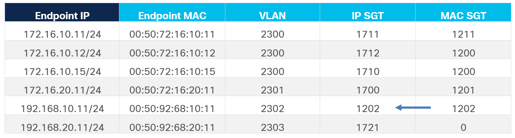
It is worth noting here that the endpoint 192.168.10.11 does not have any matching Layer-3 ESG selectors configured however, there is a matching Layer-2 (VLAN 2302) ESG selector, which derives the SGT 1202 for this endpoint’s MAC and since no SGT derived for this endpoint’s IP therefore the MAC SGT gets associated to its IP also.
On the contrary, for endpoint 192.168.20.11 only a Layer-3 ESG selector is configured matching its IP address, which derives the SGT value 1721 for its IP. Since IP SGT is never applied to the MAC, this endpoint will not derive any SGT for its MAC (hence the default SGT value of 0 is assigned to its MAC).
The above considerations raise the following question: when we have two different SGTs associated to the same endpoint, which one is going to be used for policy enforcement?
To properly answer this important question, it is first required to clarify how, in the current NX-OS GPO implementation (i.e. up to NX-OS 10.5(3) release), the forwarding lookup and the security policy lookup are performed differently for bridged and routed traffic flows.
Table 4. Forwarding lookup and Security policy lookup for bridged and routed traffic flows
| Lookup Type |
Bridged Flows |
Routed Flows |
| Forwarding Lookup |
MAC Based |
IP Based |
| Policy Lookup |
IP Based |
IP Based |
Table 4 highlights how NX-OS performs an IP-based policy lookup for both routed and bridged traffic to determine the source and destination SGTs, enabling consistent policy enforcement. This differs from traditional forwarding lookups, which rely on MAC-based lookups for bridged flows and IP-based lookups for routed flows.
An immediate consequence of this NX-OS-specific approach is that only SGT values associated with the IP addresses of endpoints are relevant, while SGT values tied to MAC addresses are ignored. This means it is essential to always learn the IP address of endpoints connected to the fabric, as policy lookups cannot be performed if only the MAC address is available.
Recognizing the importance of learning endpoint IP information, NX-OS includes specific functionalities to ensure this requirement is met, as will be discussed in the next section.
It is important to note that the current NX-OS GPO implementation cannot support non-IP communication between endpoints-i.e., packets that lack an IP header. Examples of such traffic include Ethernet protocols (e.g., STP, LLDP, CDP) or legacy/proprietary implementations like SNA, DECnet, or certain Cluster Interconnect protocols.
ARP Suppression and Punting of Traffic to the CPU
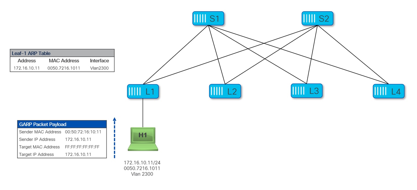
Usually, the ARP learning for endpoints happens either through GARP (Gratuitous Address Resolution Protocol) or when the host originates ARP requests to resolve the MAC address for other endpoints part of the same subnet or for the default gateway. In both cases, the Nexus 9000 switches are capable of punting the received packets to the CPU and learn from them the MAC/IP information of the connected endpoints (i.e. creating entries in the local ARP table). Once the ARP information is populated for an endpoint, a Nexus switch continuously refreshes the ARP entry by sending the ARP request to this endpoint at regular intervals, before the ARP entries expire and are removed (the default ARP cache timeout on Nexus switches is 25 minutes).
The following diagram shows the MAC/IP learning behavior for local endpoints on Nexus 9000 switches, in the specific scenario where the endpoint H1 originates a GARP packet (this could for example happen during the host’s bootup process, depending on the specific OS implementation).
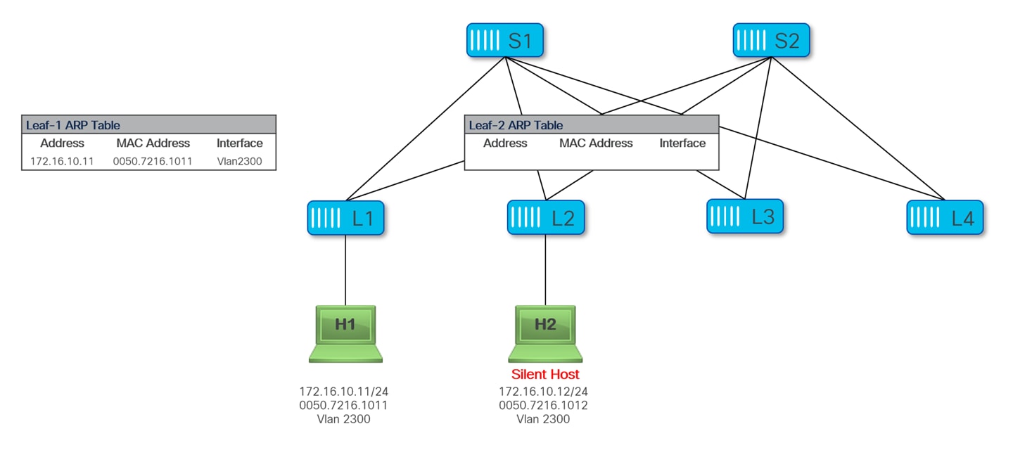
In some cases, there may be hosts that never originate ARP/GARP packets and remain therefore invisible unless some other host explicitly looks for them by sending them ARP requests. These hosts are often referred to as “silent hosts”. The following diagram shows a silent hosts H2 connected to Leaf-2; an ARP entry is not populated on Leaf-2, as it never received any ARP request from H2.
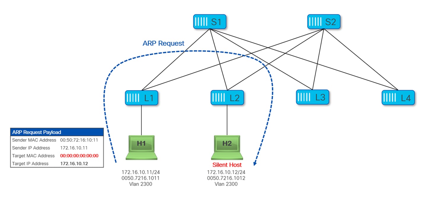
Let’s now assume that H1 wants to communicate with H2; before this communication can take place H1 needs to resolve the MAC address of H2. So H1 sends an ARP Request packet to resolve the MAC of H2, Leaf-1 floods this ARP Request into the fabric. Notice that this is the case independently from the fact that ARP suppression is enabled for that network, as H1 is not aware of the MAC of H2 (silent host).
Once H2 receives the ARP Request, it responds with a unicast ARP Reply packet, as shown in Figure 23.
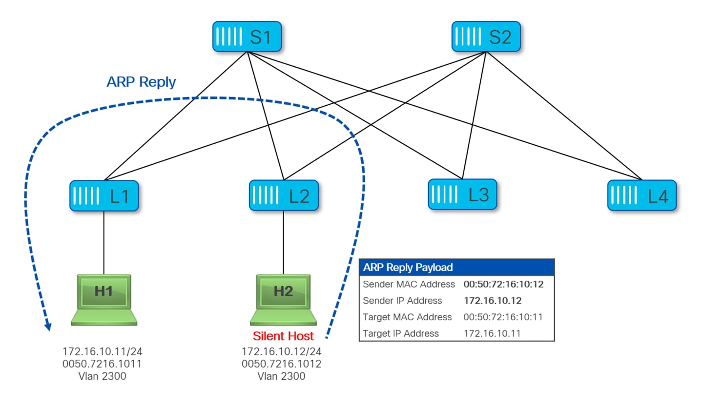
Upon receiving the ARP Reply from H2, Leaf-2 learns the MAC address of H2, but it doesn’t normally create an ARP entry for H2 (and hence does not learn its IP address), since this is a unicast ARP reply packet destined to the host H1 that gets forwarded as data-plane traffic by Leaf-2.
Note that for ARP learning to happen on a leaf from the reception of ARP Reply packets, one of the following conditions has to be met:
● The ARP Reply is destined to the VTEP’s DAG (Distributed Anycast Gateway).
● A glean operation is performed to punt the ARP Reply (not destined to the leaf) to the leaf’s CPU.
As mentioned in the previous section, learning the IP address of locally connected endpoints is critical to be able to perform policy enforcement (since the current NX-OS implementation only performs an IP based policy lookup to derive the source and destination SGT values), it is required to enable the second functionality listed above.
Up to NX-OS release 10.5(3), this mandates the enablement of ARP Suppression for L2VNIs. Once ARP suppression is enabled, the leaf performs the glean of unicast ARP replies, which in turn allows the leaf to learn the IP of the endpoint and locally install an ARP entry. Once ARP is recorded by the leaf, it can generate a Type-2 MAC-IP EVPN route for the endpoint inside the fabric and derive the source SGT based on an IP policy lookup and therefore enforce the policy (assuming the SGT for the destination endpoint is also locally known).
The following configuration snippet shows how to enable ARP Suppression for L2VNIs:
interface nve1
no shutdown
host-reachability protocol bgp
source-interface loopback1
member vni 30000
suppress-arp
mcast-group 239.1.1.0
member vni 30001
suppress-arp
mcast-group 239.1.1.0
member vni 50000 associate-vrf
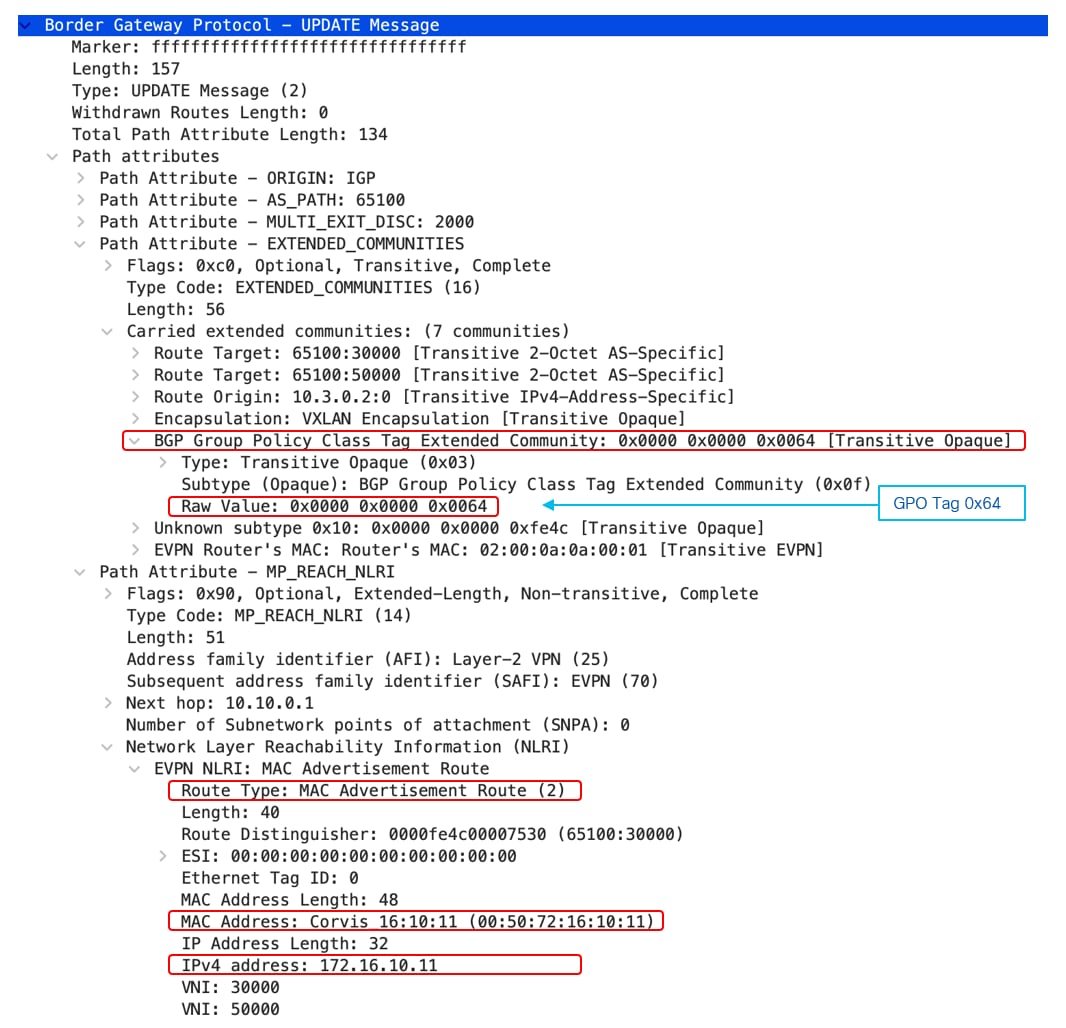
Group Policy ID (Security Group Tag) information is advertised along with EVPN routes and carried as an Extended community attribute in BGP Update messages.
The Group Policy ID BGP Extended Community is a new transitive Opaque Extended Community with a Type value of 0x03. This extended community is advertised along with the following routes:
● EVPN Type-2 MAC-IP route
● EVPN Type-5 IP Prefix route (only for external prefixes)
The following picture shows Group Policy ID BGP Extended Community for an EVPN route, we can see Group Policy ID (SGT) 0x64 which corresponds to 100 in decimal associated to Type-2 host route 172.16.10.11/32 –
Advertisement of Group Policy ID allows to perform policy enforcement on the Ingress VTEP for the flows it has learned its destination group policy tag. Otherwise policy enforcement could only be performed on the Egress VTEP and this would result in a waste of bandwidth inside the fabric (this issue is even exacerbated in Multi-Site deployments).
In the following picture, VM1 is connected to Leaf-1 and assigned SGT 100 based on its IP address. When Leaf-1 advertises the Type-2 MAC-IP EPVN route for VM1, it also advertises the SGT tag associated to this host.
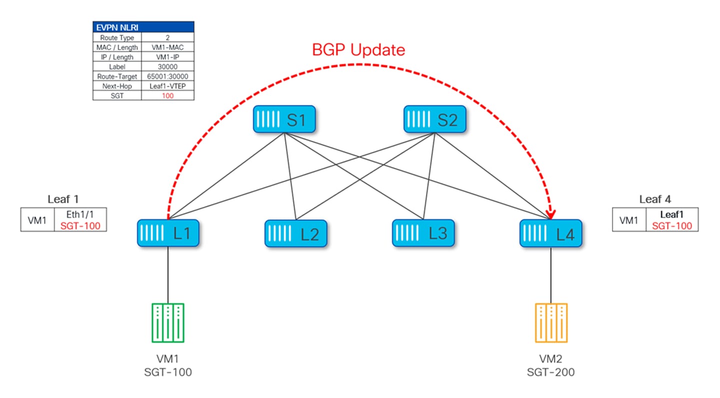
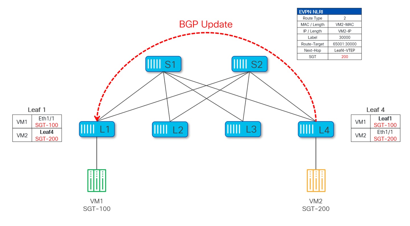
Similarly, VM2 connected to Leaf-4 is classified as part of SGT 200, and this information gets advertised through a BGP EVPN Type-2 update and learned on Leaf-1.
Group Policy Option (Security Group tag) information is also carried within GBP extension of VXLAN header in Data Plane, VXLAN header carries SGT for the source endpoint only. Carrying SGT in the VXLAN header serves two purposes:
1. Allowing policy enforcement on the egress VTEP when, for whatever reason, the SGT for the destination endpoint is unknown to the ingress VTEP. In this scenario, the Policy Applied (PA) bit is set to FALSE to signal the Egress VTEP to enforce policy before forwarding the packet to the destination.
2. Enabling the Egress VTEP to learn the SGT for the source if for some reason it wasn’t learned earlier via control-plane exchange.
The following Wireshark capture shows SGT 100 carried in data-plane inside the VXLAN header for the source endpoint 172.16.10.11.
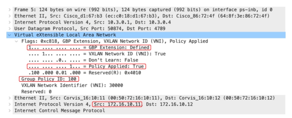
In this capture we can see that the G bit is set to 1. In addition, the Policy Applied bit is also set to 1, which indicates that the policy has already been enforced for this flow on the ingress VTEP. Upon receipt of this packet, the egress VTEP simply forwards the packet to the destination without doing any policy enforcement.
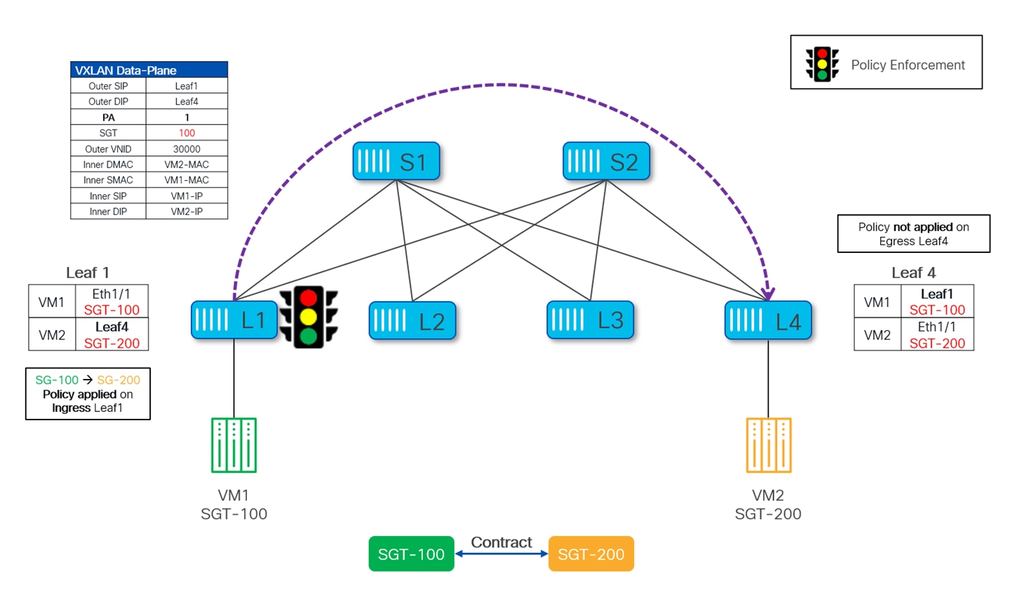
The following diagram depicts the data-plane forwarding between the source VM1 to the destination VM2. Since both source and destination SGTs are learned, security enforcement is performed on ingress Leaf1 and the Policy Applied bit (PA) is set in the VXLAN header. Upon seeing the PA bit set, the egress Leaf4 does not apply the policy and simply forwards the frame to VM2.
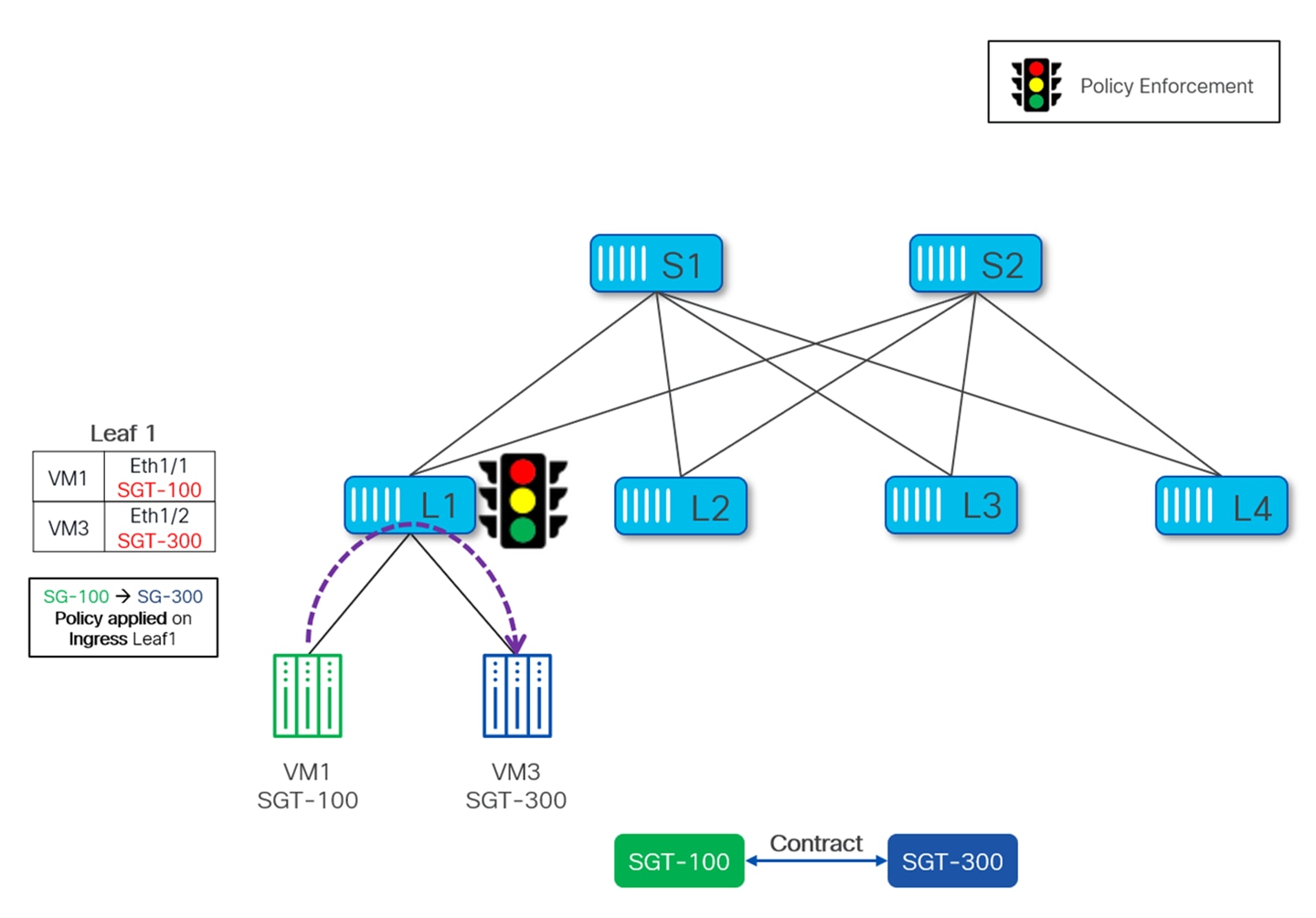
For GPO policy enforcement to take place, it is not necessary for source and destination to be connected to different VTEPs. Policy can be enforced even when both source and destinations are connected to the same VTEP and traffic between them is locally forwarded by the VTEP without requiring any VXLAN encapsulation/decapsulation. This specific scenario is shown Figure 30, where VM1 and VM3 are connected to the same VTEP Leaf-1, which enforces the policy as per the defined contract.
East-West Enforcement in Single Site
Security Group policy enforcement point in the fabric may vary depending on the fact whether the SGTs of SRC & DST are already known and the direction of the traffic. For intra-fabric traffic, enforcement is either performed on Ingress or Egress VTEP.
When enforcement is performed on the ingress VTEP, it is referred as ingress enforcement. For ingress enforcement to happen, both source security group tag (S-SGT) and destination security group tag (D-SGT) must be derived on the Ingress VTEP.
The ingress VTEP derives the SGTs as below:
● The SGT for the source endpoint is derived by performing an IP based policy lookup (once the endpoint is locally discovered) or from the ESG classification configuration on the ingress VTEP.
● The SGT for the destination endpoint must be learned from the BGP EVPN route update received from the remote VTEP and used to resolve the destination.
When the enforcement could not take place on the Ingress VTEP (when the SGT for the destination is not known to the ingress VTEP), egress enforcement is performed. In this scenario, the Ingress VTEP signals that the policy has not been applied by setting the Policy Applied bit to 0 (false) in the VXLAN GBP Extension header. Upon receiving this VXLAN packet, the Egress VTEP can then perform the policy enforcement.
To perform egress enforcement:
● The SGT for the destination endpoint is derived from the ESG configuration on the Egress VTEP.
● The SGT for the source endpoint is either learned from the BGP EVPN route update for the source or from the SGT value carried in the VXLAN header of the received packet.
East-West Enforcement in Multi-Site
VXLAN GPO based security enforcement is not only limited to a single fabric but it can also be extended across multiple fabrics which are part of the same Multi-Site domain (MSD).
In the context of Multi-Site, a GPO enabled site is referred to as Policy-Aware site while the site that is not GPO enabled is referred to as Policy-Unaware site. Coexistence of Policy-Aware and Policy-Unaware sites within the same MSD is supported, which allows implementing VXLAN GPO in the fabrics part of an existing Multi-Site domain in a phased and controlled manner.
The following scenarios are possible with respect to GPO based policy enforcement between fabrics part of the same Multi-Site domain:
● Policy-Aware to Policy-Aware
● Policy-Unaware to Policy-Aware
Note: Assumptions here is that MSD is configured for stretching both Layer-2 and Layer-3 domains across the sites.
Policy-Aware to Policy-Aware
Also referred to as Policy-Aware Multi-Site, this is the scenario where all the sites in a MSD are GPO enabled. In this case, any given traffic over Multi-Site is always between one policy-aware to another policy-aware site.
Border Gateways (BGWs) play an important role by exchanging the EVPN routes and stitching the VXLAN Tunnel to other VXLAN sites which are part of the same MSD. More details on VXLAN Multi-Site can be found in VXLAN EVPN Multi-Site Design and Deployment White Paper.
In a Policy-Aware Multi-Site scenario, EPVN routes exchanged between the BGWs of different sites also carry the SGT information as BGP extended community attribute. These EVPN routes (along with their SGT values) are then propagated to the site local VTEPs and used for policy enforcement. Since all the sites in MSD are policy-aware therefore policy is always enforced on the ingress VTEP provided both Src and Dst SGTs are learned.
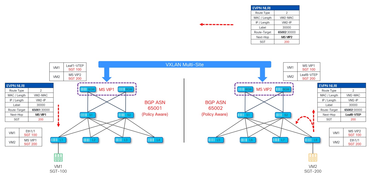
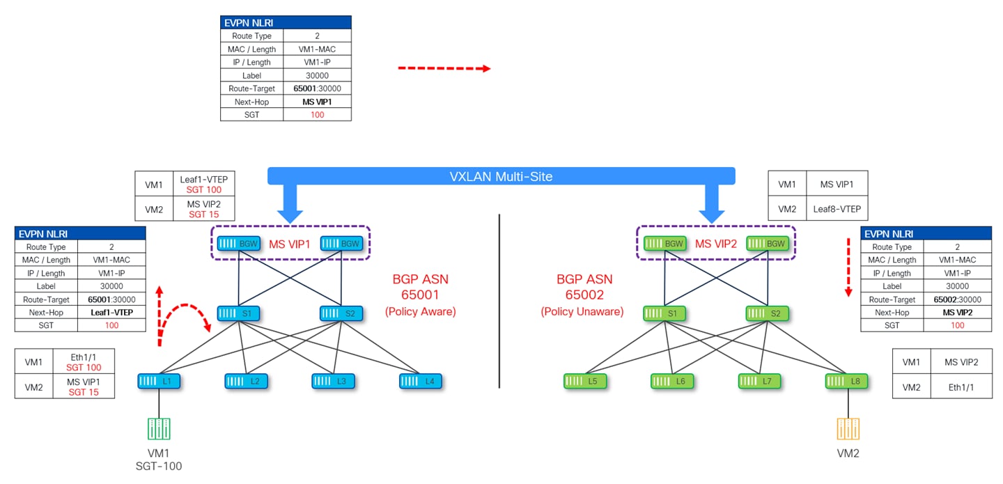
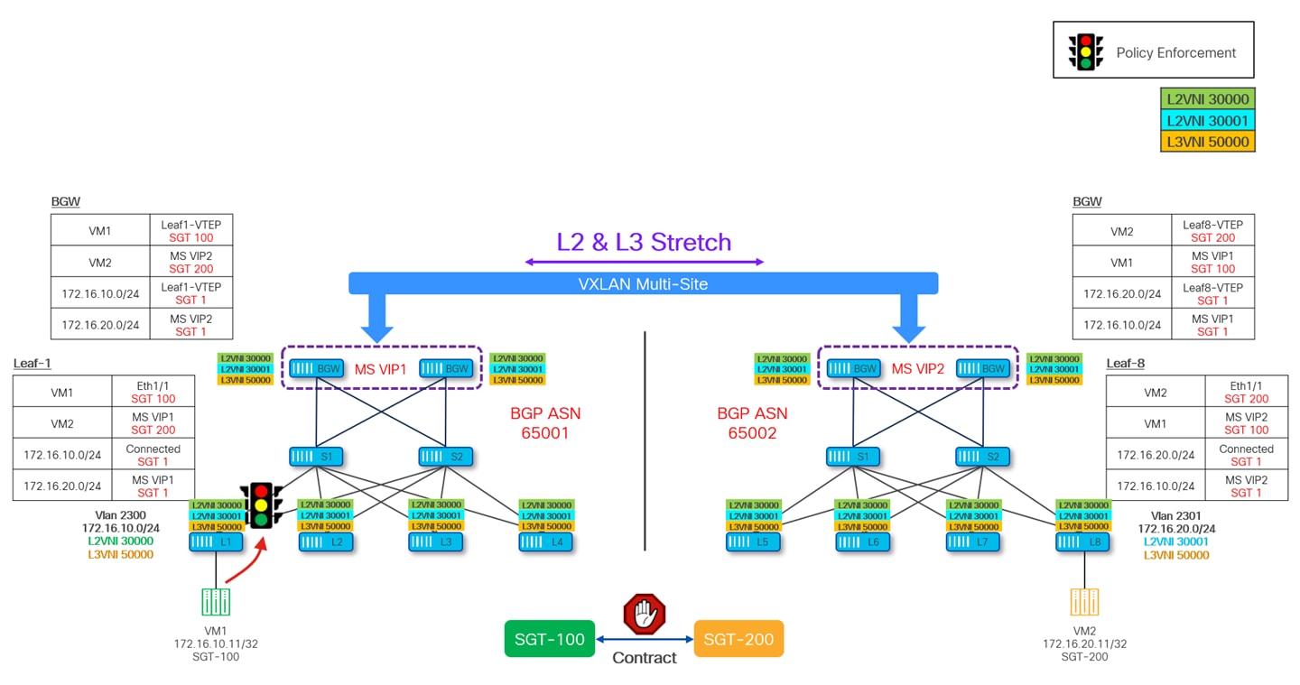
The diagram given below depicts how the SGT of VM1 connected to site-1 (BGP ASN 65001) is being advertised inside the MSD.
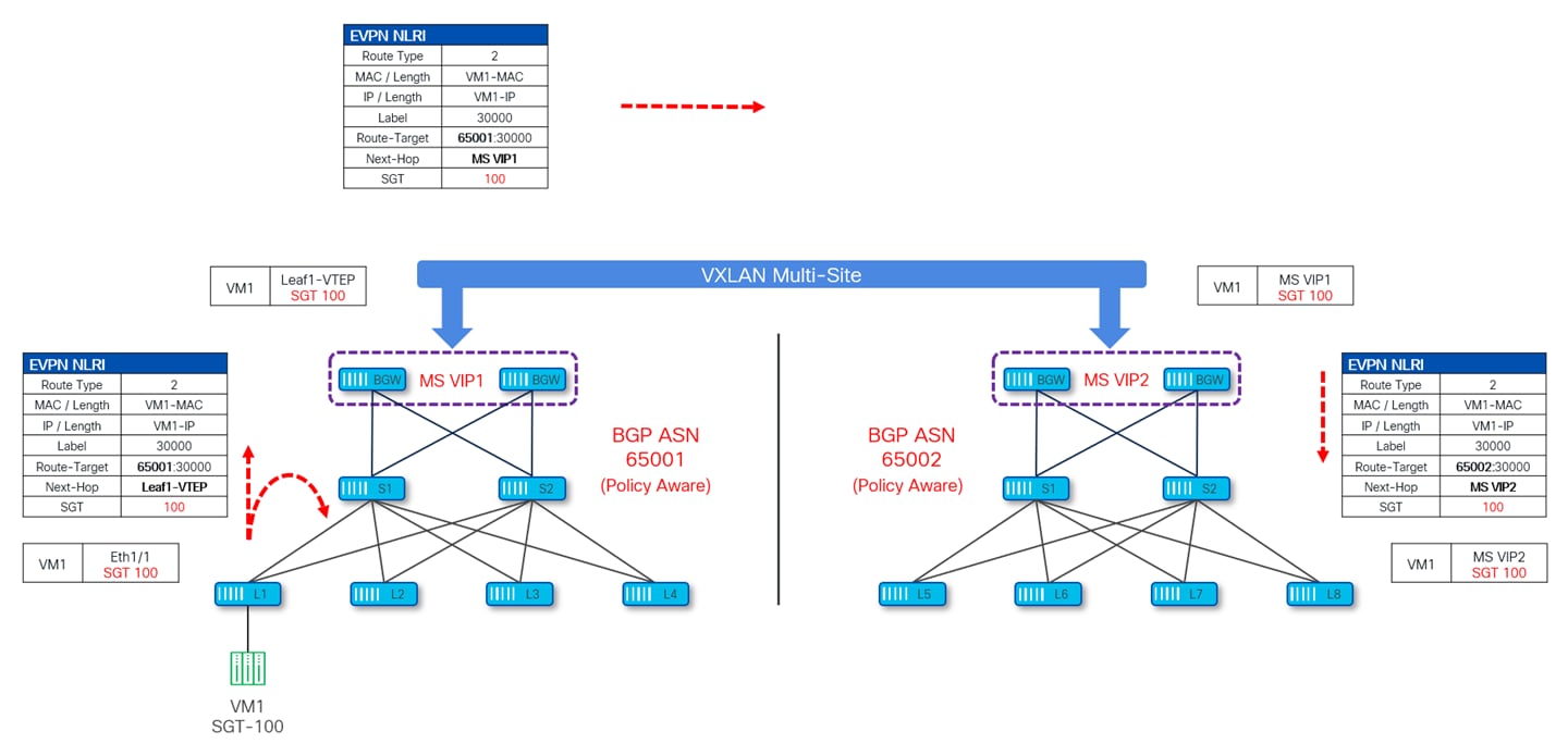
Leaf-1 (where this VM1 is connected) is advertising the SGT along with the EVPN Type-2 update which gets advertised to all the VTEPs including the site local BGWs. Site-1 BGWs then send this update to Site-2 (BGP-ASN 65002) by changing the next-hop IP to their own Multi-Site VIP IP (MS VIP1). Upon receiving this update, Site-2 BGWs change the Route-Target and next-hop to Site-2 Multi-Site VIP IP (MS VIP2) and pass this update to all the VTEPs inside site-2. Throughout this exchange of information, the SGT value is carried as a Transitive Community attribute in the BGP update.
Similarly, the BGP EVPN update for VM2 at site-2 also takes place as shown in Figure 32.
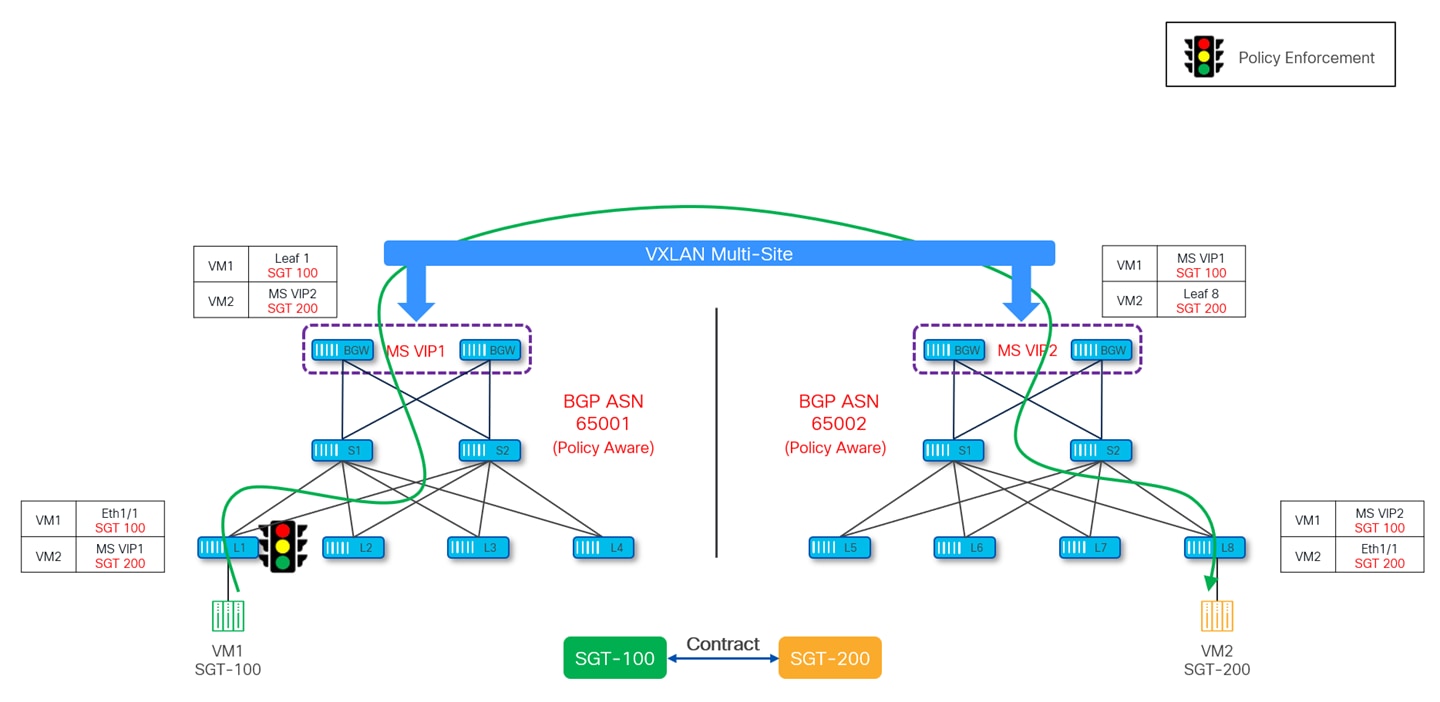
Once the SGTs for source and destination endpoints are learned, policy can be applied on the ingress leaf. As shown in Figure 33, policy is enforced on leaf1 at site-1, which happens to be the ingress leaf for traffic originating from VM1 at site-1 and destined to VM2 at site-2. Leaf-1 would also set PA bit in VXLAN header so that other VTEPs (site-local BGW, remote BGW and egress Leaf-8) along the path don’t reapply the policy.
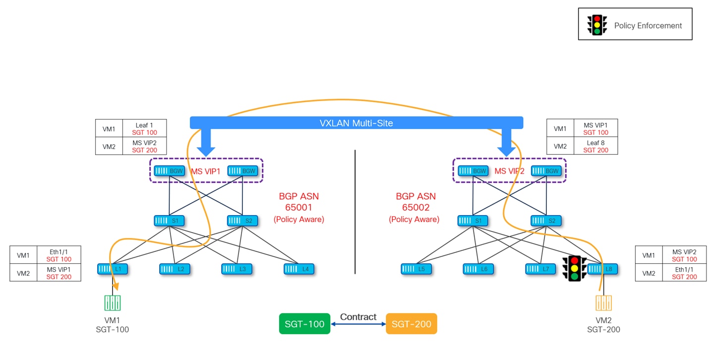
Similarly, if traffic is originating from VM2 at site-2 and destinated to VM1 at site-1, policy is enforced on leaf-8 in site-2.
Policy-Unaware to Policy-Aware
This scenario is also referred to as Policy-Unaware Multi-Site. NX-OS supports policy enforcement in a Multi-Site domain even when one or more sites are not GPO capable. To enable policy enforcement in a Policy-Unaware MSD, at least one site needs to be GPO enabled.
There can be multiple reasons for having policy-unaware site in MSD such as VTEPs in policy-aware site are not GPO capable due to Sw/Hw limitation or a site is in transition phase of enabling VXLAN GPO. Nonetheless, it is important to support policy enforcement in this scenario.
Since in this case all the sites which are part of same MSD are not GPO enabled, there might be situations where a given traffic flow over Multi-Site is between two policy-aware sites. In that case, control-plane and data-plane operations mentioned in previous section (Policy-Aware to Policy-Aware) gets applied. If, instead, flows are between endpoints part of non-GPO enabled fabric, regular Layer-2/Layer-3 Multi-Site forwarding happens and there is no policy enforcement at all.
The remaining of this section explains control-plane and data-plane operations in case of traffic flows between policy-aware and policy-unaware sites part of the same MSD.
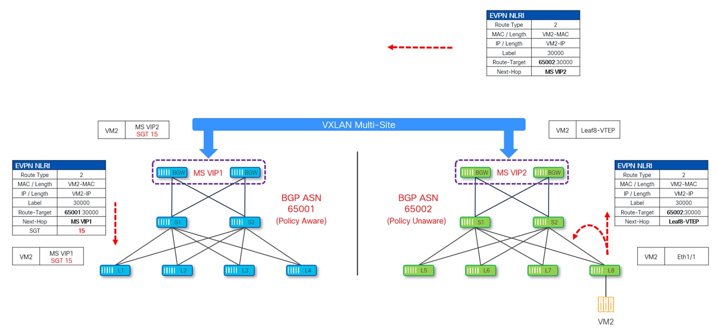
NX-OS uses a special SGT 15 value (part of the reserved range and referred to as default policy-unaware tag) for this specific use case. All Type-2 and Type-5 EVPN routes originating from a policy-unaware site get classified on the BGWs of a policy-aware fabric with this default policy-unaware tag.
EVPN routes originating from a policy-unaware site do not carry any SGT information (as the site is not GPO enabled). When this update reaches the BGWs of a policy-aware site, they automatically assign SGT 15 to all the type-2 and type-5 routes received from policy-unaware site and propagate this update to the rest of the VTEPs inside the local site.
The following diagram depicts how the EVPN type-2 advertisement for VM2 originating from a policy-unaware Site-2 do not carry any SGT value. Upon receiving this update at policy-aware Site-1, the BGWs assign to it the default SGT 15 tag. As always, the BGWs also rewrite the next-hop and BGP ASN information before propagating this update to the rest of the local VTEPs.
On the other hand, EVPN routes originating from a policy-aware site derive SGT from the configuration. When the EVPN route is advertised it carries the SGT as extended community Optional Transitive attribute in BGP update message. This update is propagated to all the VTEPs (including site local BGWs) locally, site local BGWs then forward this update to the BGWs of remote site in same MSD. Since SGT is carried as Optional Transitive attribute it remains part of the BGP update throughout regardless of whether it is recognized by remote VTEPs.
When this update is received at policy-unaware site, this SGT field is simply ignored, and the rest of the update is processed.
Since in this case not all the sites part of the Multi-Site domain are GPO enabled, it is very important to understand how and where contracts need to be defined and where they are enforced. First of all, the contracts are only defined in the policy-aware sites part of the MSD, by definition there are no contracts defined and enforced in policy-unaware sites.
As all the policy-unaware Type-2 and Type-5 EVPN routes get default SGT 15 assigned, a valid contract must then be associated to this SGT 15 security group to allow communication between policy-aware and policy-unaware sites.
The following diagram depicts an SGACL Contract defined on all the VTEPs (leaf and BGW nodes) of a policy-aware site.
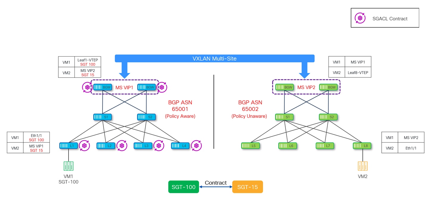
In the above diagram, the contract is applied between SGT-100 defined in the policy aware site and representing the security group VM1 is part of, and SGT-15 representing all the endpoints part of remote policy unaware sites (VM2 in our specific example).
About the enforcement of the security policy, it is advantageous to define the contract closest to the source to avoid unnecessary waste of fabric bandwidth.
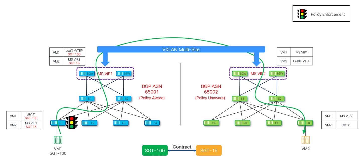
Policy is always enforced on the policy-aware site as the other site which is policy-unaware cannot perform any enforcement. Policy enforcement happens at different points depending on the direction of the traffic flow:
● Ingress Leaf – If the source is located in the policy-aware site and the destination is located in the policy-unaware site, the security policy is enforced on the ingress leaf of the policy-aware site.
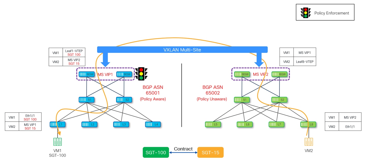
● Policy-Aware BGW – If the source is located in the policy-unaware site and the destination is located in the policy-aware site, the security policy is enforced on the BGWs of the policy-aware site.
The following diagram depicts the policy being enforced on the ingress leaf of the policy-aware site when traffic is locally originated.
The diagram below shows the policy enforcement happening on the policy-aware BGWs when traffic originated from the policy-unaware sites and destined to the policy-aware site.
Considerations and Guidelines with Multi-Site Policy Enforcement
The deployment of VXLAN Multi-Site provides layer-3 connectivity as well as layer-2 stretching between the sites, depending on the specific connectivity requirements.
In the scenario where L2 networks are not stretched between fabrics but only locally defined in the local fabrics, only Layer-3 connectivity between fabrics is required. In such case, it has been the best practice recommendation to only deploy the L3VNIs on the BGWs of different VXLAN fabrics to functionally stretch the VRF and allow the required inter-fabric routed connectivity. By doing so, only EVPN Type-5 routes for the local subnets were advertised across fabrics, whereas no Type-2 information was ever exchanged (as it was not needed to have granular endpoint level information if the subnet was not stretched across sites).
The following diagram shows the example of L3 stretching between the sites.
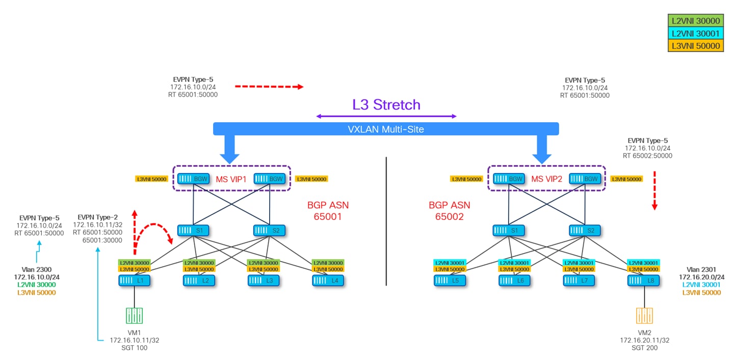
When enabling GPO in a VXLAN Multi-Site deployment, the best practice recommendation mentioned above must be revisited. To understand why, please refer to the scenario shown in Figure 41.
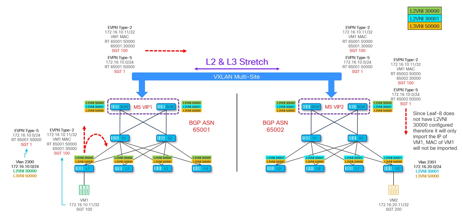
Leaf-1 has a locally deployed SVI for VLAN 2300 (172.16.10.0/24) and is therefore generating a Type-5 EVPN route to advertise this subnet with SGT 1 and RT 65001:50000. Leaf-1 is also advertising a Type-2 prefix for endpoint VM1 (172.16.10.11, VLAN 2300) carrying SGT 100 (the security group VM1 is classified in) and RT 65001:30000 and 65001:50000. Since the requirement is only to stretch L3 connectivity between the fabrics, the BGWs of both sites are only configured with L3VNI 50000 following the best practice configuration shown in previous Figure 40.
As a result, only the Type-5 EVPN routes are exchanged between the BGWs of the two sites and imported in their local BGP tables and VRF routing tables based on the matching of the L3VNI (VRF) RT import value configured on them. The IP portion of the Type-2 route originated from Leaf-1 is imported by the site local BGWs (in the BGP table and VRF routing table) but it is not advertised to the remote site BGWs.
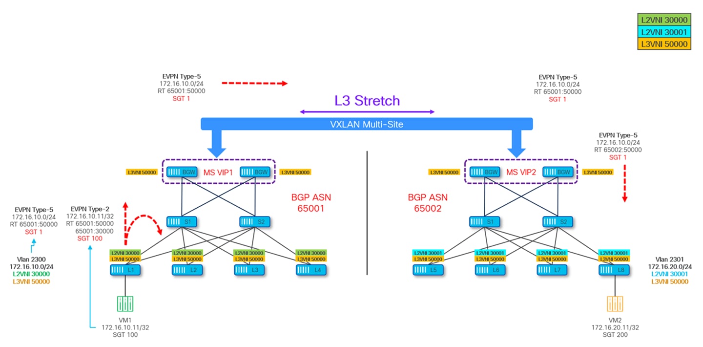
EVPN Type-5 route exchange for the directly connected subnets is sufficient for providing L3 connectivity between the sites; however, it poses a unique problem when it comes to GPO policy enforcement. Let’s understand that with the help of next diagram:
Figure 42 depicts the control-plane information for the various devices part of the Multi-Site domain, where Site-2 does not have information of the SGT for VM1 because the EVPN Type-2 route did not make to Site-2, and similarly the SGT of VM2 is not known to Site-1.
In this scenario if VM1 at Site-1 initiates a communication to VM2 at Site-2, the policy is neither enforced on the source VTEP Leaf-1 nor on the Site-1 BGWs as they cannot derive the specific SGT values of the VM2 destination (only the SGT 1 value associated to the remote 172.16.20.0/24 subnet can be derived).
Consequently, the policy enforcement is delayed until this packet reaches the destination site, specifically the BGWs of Site-2 that are aware of the SGT for destination VM2 and enforce the policy as per the deny contract and drops the packet.
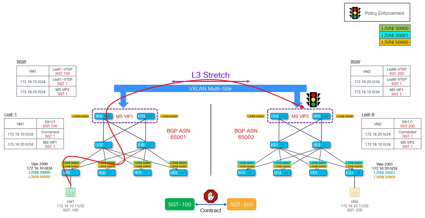
Likewise, if the traffic is initiated from Site-2, the policy enforcement is delayed until the packet reaches the BGWs in Site-1. This behavior is undesirable as the packet is forwarded all the way to the destination site consuming network resources and bandwidth and then meeting its fate.
To optimize policy enforcement in this situation, it is recommended to always define the L2VNIs on all the BGWs of the fabrics part of the Multi-Site domain (in addition to the VRFs/L3VNIs that need to be stretched). When doing so, two different scenarios are possible:
Scenario 1: The L2VNI represents a subnet extended across multiple sites, requiring it to be configured not only on all BGWs but also on the leaf nodes within the fabrics where the subnet is stretched. This ensures that detailed MAC/IP endpoint information, along with associated SGT values, is distributed through EVPN Type-2 advertisements to the leaf nodes in each fabric. As a result, ingress leaf nodes can consistently enforce policies based on the flow direction.
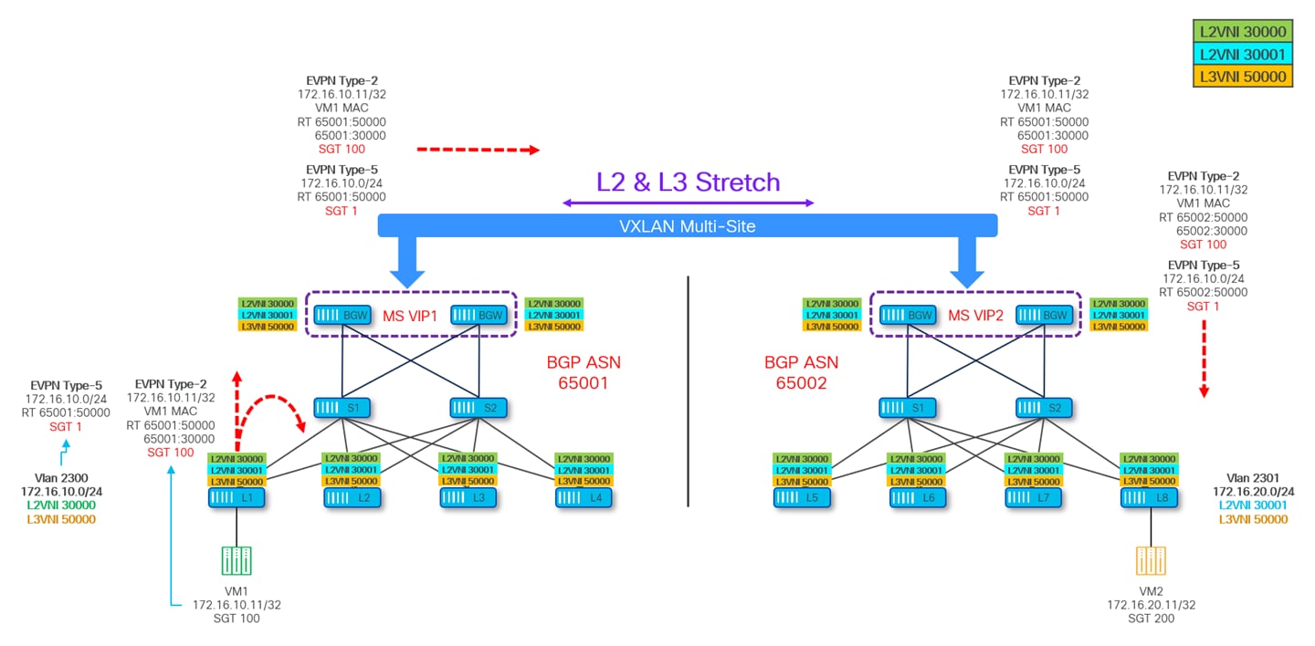
Scenario 2: The L2VNI represents a subnet confined to a specific fabric, meaning it is only configured on the leaf nodes within that fabric, as well as on all BGWs. This setup triggers the propagation of Type-2 routes containing MAC/IP endpoint information and SGT values from the local site's BGWs to the remote sites. In the remote sites, the BGWs advertise this information within each fabric; however, only the IP portion (along with the corresponding SGT value) is imported onto the leaf nodes where the VRF is defined. The MAC portion is not installed because the L2VNI is not configured on the leaf nodes of the remote sites.
In summary, while advertising Type-2 routes serves as an optimization for policy enforcement in hardware on ingress leaf nodes, it becomes a mandatory requirement when traffic redirection to a service node (or service chain) is needed for inter-site communications between endpoints. As a general best practice, it is strongly recommended to ensure that all defined L2VNIs are consistently configured on the BGWs of all fabrics within a Multi-Site domain.
North-South Policy Enforcement
Until now we have looked at GPO policy enforcement for East-West communication, be it intra-site or inter-site. In both cases, it was always end-to-end VXLAN encapsulated traffic. This section describes GPO policy enforcement for North-South communication, where traffic is forwarded between the VXLAN fabric and external networks.
In the context of VXLAN, any network which is outside of the VXLAN fabric is referred to as external network or prefix. There are various connectivity options when it comes to connecting VXLAN fabrics to external networks. While IP-based VRF-Lite handoff is more common option to connect VXLAN fabric to a legacy network, NX-OS also supports connecting VXLAN fabric to MPLS networks using MPLS and MPLS-SR based handoff. Nonetheless, whichever external connectivity options are used, all of them are well supported with VXLAN GPO based policy enforcement.
The VTEP device where this VRF-Lite handoff is performed is called Border Leaf device and is responsible for doing VXLAN to IP handoff. All the external routes learned on this Border Leaf are converted to EVPN Type-5 prefixes and get advertised to the rest of the VTEPs inside the VXLAN fabric.
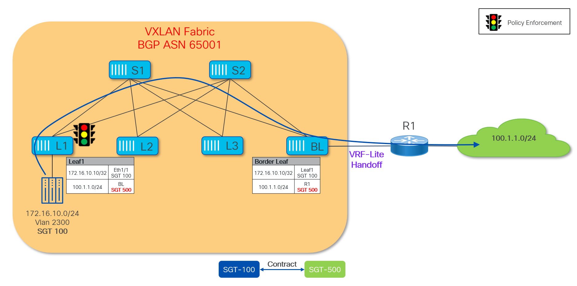
Since the GPO capability is currently limited to VXLAN EVPN control and data planes, SGTs cannot be exchanged between the VXLAN fabric and the external networks. Therefore, it is mandatory to classify and assign SGTs to external resources in order to perform policy enforcement for north-south traffic flows. The Border Leaf nodes in the VXLAN fabric represent the ideal place to perform the classification and SGT assignment for external prefixes. Once an SGT value is assigned to an external prefix it will get carried along with the EVPN Type-5 update and advertised inside the VXLAN fabric.
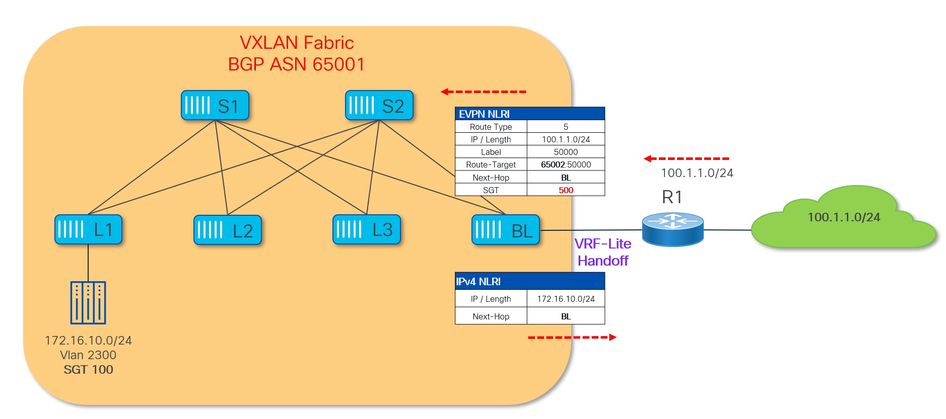
The diagram above shows a VRF-Lite handoff between a VXLAN fabric and the external network domain. The Border Leaf (BL) in the VXLAN fabric is configured to classify the received external prefix 100.1.1.0/24 to SGT 500.
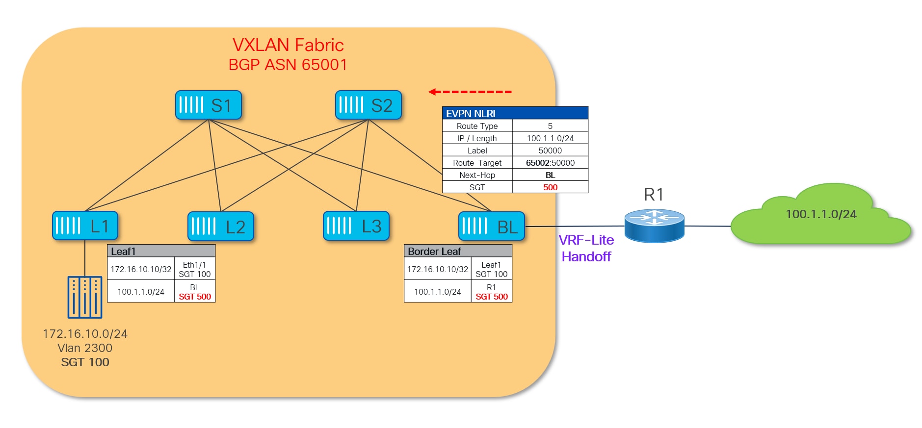
The external prefix and its associated SGT value is then propagated inside the fabric and received and installed on all the leaf nodes where that VRF is deployed. Once that is done, the security policy can then be enforced. Figure 48 highlights how the policy can be enforced on the ingress VTEP for traffic originating within the VXLAN fabric and destined to the external network.
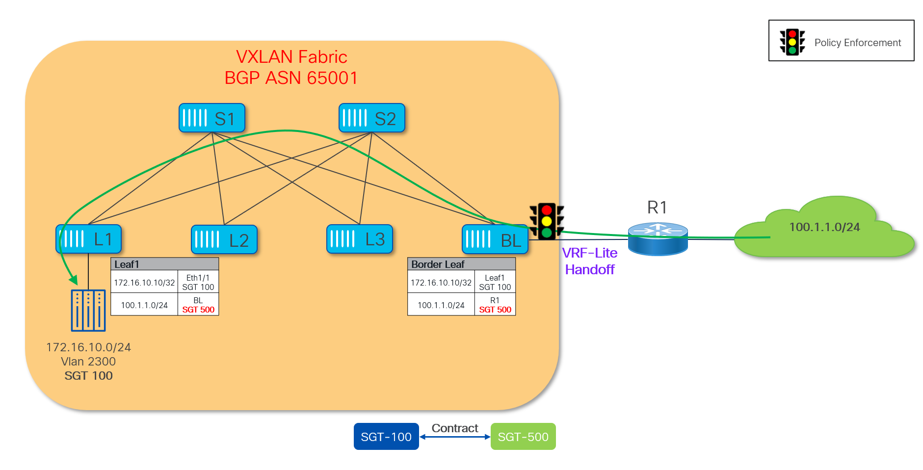
In the reverse direction, any traffic originating from the external network will have the security policy enforced on the entry point of the VXLAN fabric which is the Border Leaf node (Figure 49).
Note: For more information on how to apply security policies with external destinations in more complex scenarios, see “Use-Case: Policy Enforcement for North-South traffic” section covered later in this document.
Use-Cases and Configuration Examples
Policy Enforcement for East-West
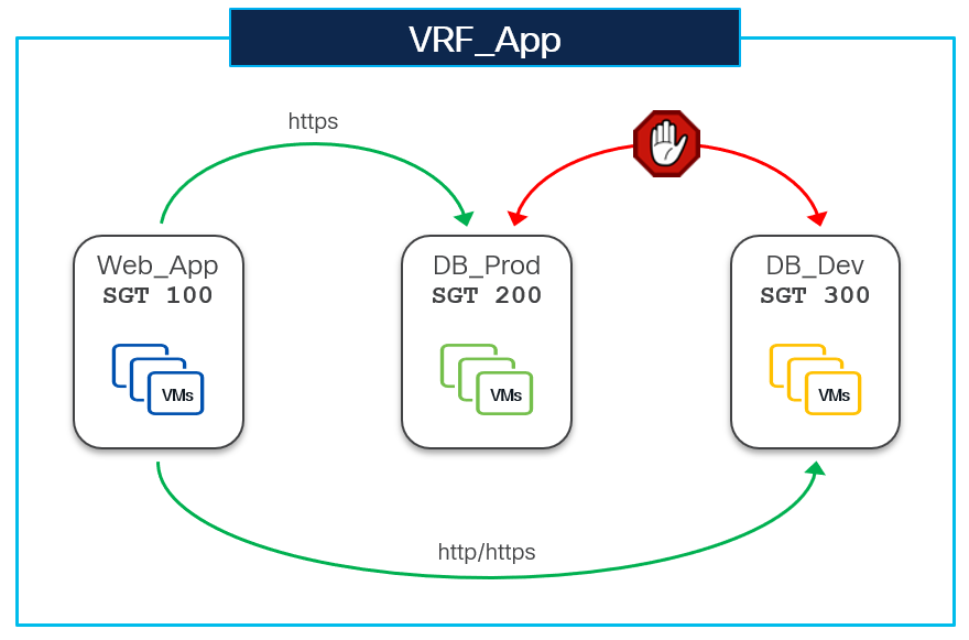
This section demonstrates how to configure East-West Intra-Tenant security enforcement using VXLAN GPO. The VRF-App VRF represents a tenant on the VXLAN fabric. Endpoints in this VRF are categorized in three different security groups based on their function and traffic profile.
● Security group DB_Prod (SGT 200) contains database servers in the production environment.
● Security group DB_Dev (SGT 300) also contains database servers but in the non-production environment.
● Security group Web_App (SGT 100) contains web application servers.
In this example we are using host-centric approach, therefore endpoints are classified to security groups using IPv4 host routes (/32) .
● The following endpoints are mapped to DB_Prod SG:
◦ 192.168.10.11 and 192.168.10.12 connected to Leaf-1
◦ 192.168.10.21 and 192.168.10.22 connected to Leaf-2
● The following endpoints are mapped to DB_Dev
◦ 192.168.20.11 and 192.168.20.12 connected to Leaf-2
● The following endpoints are mapped to Web_App SG:
◦ 172.16.10.11 and 172.16.10.12 connected Leaf-4
◦ 172.16.20.11 and 172.16.20.12 connected to Leaf-4
In this topology Leaf-3 does not have any SG configured.
The intent here is to allow HTTPs traffic between source SG Web_App and destination SG DB_Prod and to allow HTTP/HTTPs traffic between source SG Web_App and destination SG DB_Dev. All the rest of the communication should be blocked.
Configuration
Note: For brevity, underlay and other trivial configuration parts have been skipped. For VXLAN best practices design and configuration it is recommended to refer to the Cisco Nexus 9000 VXLAN BGP EVPN Data Center Fabrics Fundamental Design and Implementation Guide.
The following sections show basic overlay configuration snippets from all the leaf nodes, which ensures network connectivity between the endpoints and the VXLAN EVPN fabric.
Overlay Tenant VRF Configuration
All Leafs (L1-L4):
vrf context VRF_App
vni 50000 l3
rd auto
address-family ipv4 unicast
route-target both auto
route-target both auto evpn
address-family ipv6 unicast
route-target both auto
route-target both auto evpn
interface nve1
no shutdown
host-reachability protocol bgp
source-interface loopback1
member vni 50000 associate-vrf
router bgp 65001
vrf VRF_App
address-family ipv4 unicast
advertise l2vpn evpn
redistribute direct route-map fabric-rmap-redist-subnet
maximum-paths ibgp 2
address-family ipv6 unicast
advertise l2vpn evpn
redistribute direct route-map fabric-rmap-redist-subnet
maximum-paths ibgp 2
Note: The above example demonstrates the new L3VNI Mode configuration. The New L3VNI Mode helps in achieving higher scale (2K VRFs & 4K Networks per node).
Overlay Networks Configuration
Leaf-1:
route-map fabric-rmap-redist-subnet permit 10
match tag 12345
vlan 2302
vn-segment 30002
interface Vlan2302
vrf member VRF_App
ip address 192.168.10.1/24 tag 12345
fabric forwarding mode anycast-gateway
no shutdown
interface nve1
member vni 30002
mcast-group 239.1.1.1
evpn
vni 30002 l2
rd auto
route-target import auto
route-target export auto
interface ethernet1/1
switchport
switchport mode trunk
switchport trunk allowed vlan 2302
spanning-tree port type edge trunk
mtu 9216
no shutdown
Leaf-2:
route-map fabric-rmap-redist-subnet permit 10
match tag 12345
vlan 2302
vn-segment 30002
vlan 2303
vn-segment 30003
interface Vlan2302
vrf member VRF_App
ip address 192.168.10.1/24 tag 12345
fabric forwarding mode anycast-gateway
no shutdown
interface Vlan2303
vrf member VRF_App
ip address 192.168.20.1/24 tag 12345
fabric forwarding mode anycast-gateway
no shutdown
interface nve1
member vni 30002
mcast-group 239.1.1.1
member vni 30003
mcast-group 239.1.1.1
member vni 30120
mcast-group 239.1.1.1
evpn
vni 30002 l2
rd auto
route-target import auto
route-target export auto
vni 30003 l2
rd auto
route-target import auto
route-target export auto
interface ethernet1/1
switchport
switchport mode trunk
switchport trunk allowed vlan 2303
spanning-tree port type edge trunk
mtu 9216
no shutdown
interface ethernet1/2
switchport
switchport mode trunk
switchport trunk allowed vlan 2302
spanning-tree port type edge trunk
mtu 9216
no shutdown
Leaf-4:
route-map fabric-rmap-redist-subnet permit 10
match tag 12345
vlan 2300
vn-segment 30000
vlan 2301
vn-segment 30001
interface Vlan2300
vrf member VRF_App
ip address 172.16.10.1/24 tag 12345
fabric forwarding mode anycast-gateway
no shutdown
interface Vlan2301
vrf member VRF_App
ip address 172.16.20.1/24 tag 12345
fabric forwarding mode anycast-gateway
no shutdown
interface nve1
member vni 30000
mcast-group 239.1.1.1
member vni 30001
mcast-group 239.1.1.1
evpn
vni 30000 l2
rd auto
route-target import auto
route-target export auto
vni 30001 l2
rd auto
route-target import auto
route-target export auto
interface ethernet1/1
switchport
switchport mode trunk
switchport trunk allowed vlan 2300,2301
spanning-tree port type edge trunk
mtu 9216
no shutdown
Enable Security Group Routing Template
Before starting the GPO configuration, all the leaf nodes (VTEPs) in the fabric must be configured with the security group routing template that carves out the forwarding table (FIB) for storing SGTs along with the EVPN route. Since VXLAN EVPN routes are only programmed in the FIB of the VTEPs, the enablement of the SG routing template is not required on the spines, except for the scenarios where the spines are also performing VTEP functions (in case of Border Spine, BGW Spines, etc.).
Use the following CLI command on the leaf nodes to enable the SG routing template:
system routing template-security-groups
Note: Changing routing template on the Nexus 9000 switches requires reloading of the device, therefore save the configuration and reload the device for SG routing template to take effect.
Once the device comes back up after the reload, verify the system routing mode using the following CLI command:
Leaf4# show system routing mode
Configured System Routing Mode: Security-Groups Support
Applied System Routing Mode: Security-Groups Support
Leaf4#
Enable VXLAN GPO Feature
After the SG routing template has been enabled on all the leaf nodes, the next step is to enable the GPO feature using the following CLI:
feature security-groups
Note: Configuring the Security Group routing template (and reloading the switches) is a prerequisite to enable the GPO feature.
Create Security Group
Leaf-1:
security-group 200 name DB_Prod
match connected-endpoints vrf VRF_App ipv4 192.168.10.11/32
match connected-endpoints vrf VRF_App ipv4 192.168.10.12/32
Leaf1# show security-group id all
Security Group ID 200 , Name DB_Prod
Selector Type : Connected IPv4 Endpoints
VRF-Name IPv4-Address/mask-len
VRF_App 192.168.10.11/32
VRF_App 192.168.10.12/32
Leaf1#
Leaf-2:
security-group 200 name DB_Prod
match connected-endpoints vrf VRF_App ipv4 192.168.10.21/32
match connected-endpoints vrf VRF_App ipv4 192.168.10.22/32
security-group 300 name DB_Dev
match connected-endpoints vrf VRF_App ipv4 192.168.20.11/32
match connected-endpoints vrf VRF_App ipv4 192.168.20.12/32
Leaf2# show security-group id all
Security Group ID 200 , Name DB_Prod
Selector Type : Connected IPv4 Endpoints
VRF-Name IPv4-Address/mask-len
VRF_App 192.168.10.21/32
VRF_App 192.168.10.22/32
Security Group ID 300 , Name DB_Dev
Selector Type : Connected IPv4 Endpoints
VRF-Name IPv4-Address/mask-len
VRF_App 192.168.20.11/32
VRF_App 192.168.20.12/32
Leaf2#
Leaf-4:
security-group 100 name Web_App
match connected-endpoints vrf VRF_App ipv4 172.16.10.11/32
match connected-endpoints vrf VRF_App ipv4 172.16.10.12/32
match connected-endpoints vrf VRF_App ipv4 172.16.20.11/32
match connected-endpoints vrf VRF_App ipv4 172.16.20.12/32
Leaf4# show security-group id all
Security Group ID 100 , Name Web_App
Selector Type : Connected IPv4 Endpoints
VRF-Name IPv4-Address/mask-len
VRF_App 172.16.10.11/32
VRF_App 172.16.20.11/32
VRF_App 172.16.10.12/32
VRF_App 172.16.20.12/32
Leaf4#
Note: In the above example SG classification rules are configured only the respective leaf nodes where the endpoints are locally connected. However, it is good practice to configure consistent SG classification rules on all the leaf nodes to support host mobility.
Create Security Group Contracts
The following section shows the configuration required for policy enforcement to allow HTTPs (TCP Dst port 443) traffic between source SG Web_App and destination SG DB_Prod as shown in the following figure.
Web_App SG is only present on Leaf4 while DB_Prod SG is spread across Leaf2 and Leaf4.
Create Traffic Selector and Enforcement Policy
First create a security class-map to match HTTPs traffic and then reference this class-map under a security policy-map to define the enforcement action (permit/deny/redirect/log) to be taken on the matched traffic, as shown below.
Note: The following configuration needs to be applied on all the leaf nodes where SG Web_App and DB_Prod endpoints are present.
Leaf-1, Leaf-2, and Leaf-4:
class-map type security match-any web_https
match ip tcp dport 443
policy-map type security permit_web_port-443
class web_https
permit
log
Note: As permit being the default action, it does not appear in the running-config unless all keyword is used with show command.
Leaf1# show class-map type security
class-map type security match-any web_https
match ip tcp dport 443
Leaf1# show policy-map type security
Type security policy-maps
=========================
policy-map type security permit_web_port-443
class web_https
permit
log
Leaf1#
Define Contracts (SGACLs)
SGACLs (or contracts) bind SGs with enforcement policies along with enforcement direction. To allow HTTPs traffic between source SG Web_App (SGT 100) and destination SG DB_Dev (SGT 200), the permit_web_port-443 policy created in the previous section needs to be associated with source and destination SGTs.
Leaf-1, Leaf-2, and Leaf-4:
vrf context VRF_App
security contract source 100 destination 200 policy permit_web_port-443 bidir
Note: As bidir is the default direction, it does not appear in the running-config unless all keyword is used with show command.
Leaf1# show contracts
VRF SGT DGT Policy Dir Stats Class Action OperSt
-----------------------------------------------------------------------------------------
VRF_App 100 200 permit_web_port-443 bidir 0 web_https permit,log enabled
Leaf1#
Leaf1# show contracts detail
VRF: VRF_App
Contract source group 100 dest group 200
Policy: permit_web_port-443 Direction: bidir
Stats: 0
Class: web_https
match ip tcp dport 443
Action: permit,log
OperSt: enabled
Leaf1#
Set VRF Enforcement mode
The final and the most important step is to change the VRF enforcement mode. By default, a VRF is in unenforced mode and unless it is changed to enforced mode no policy takes effect. Here, VRF_App is being changed to enforced mode default-deny, which ensures to implement a zero-trust security model.
Leaf-1, Leaf-2, and Leaf-4:
vrf context VRF_App
security enforce tag 999 default deny
When a VRF is changed to enforced mode it requires a tag for the VRF (999 in the above example). This tag is referred as VRF tag and used by NX-OS in creating an implicit permit rule. This implicit permit rule is used in the forwarding of BUM traffic as well as deriving contracts for the SIP/DIP which are not present in FIB for some reason.
Leaf1# show vrf VRF_App security
VRF Mode TAG Action Scope Stats
----------------------------------------------------------------------------------------
VRF_App enforced 999 permit 1 10583
Leaf1#
The following section shows the configuration required for security enforcement to allow HTTP/HTTPs (TCP Dst port 80/443) traffic between source SG Web_App and destination SG DB_Dev, as shown in the following figure.
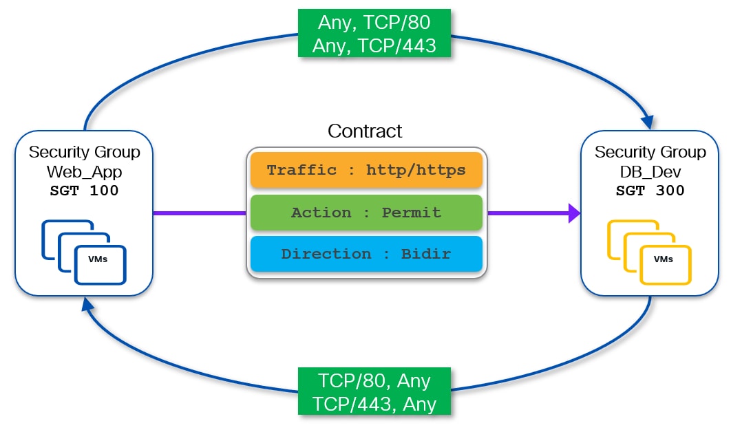
Web_App SG is present on Leaf-4 while DB_Dev SG is present on Leaf-2.
Create Traffic Selector and Enforcement Policy
In order to allow both HTTP and HTTPs traffic, we must create a new class-map and policy-map and also the contract needs to be defined between S-SGT 100 and D-DGT 300 (the rest of the configuration is similar to the one described in the previous step).
Leaf-2 and -4:
class-map type security match-any web_http_https
match ip tcp dport 80
match ip tcp dport 443
policy-map type security permit_web_port-80_443
class web_http_https
permit
log
Define SGACL Contracts
Leaf-2 and -4:
vrf context VRF_App
security contract source 100 destination 300 policy permit_web_port-80_443
As the VRF is already set in default deny enforcement mode, we don’t need to repeat that configuration.
Having the VRF in default deny mode requires a permit contract before any communication can take place over the fabric. In previous steps we have defined permit rules between SGT 100 and SGT 200 and between SGT 100 and SGT 300. As a result, an implicit “deny all” rule is applied between SGT 200 and SGT 300, which can’t therefore communicate.
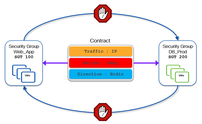
If the VRF had been set in default-permit mode, an explicit deny contract would have been required to block the traffic between SGT 200 and SGT 300.
Policy Enforcement for North-South
This section demonstrates how GPO based security enforcement can be performed for the traffic in N-S direction. For this demonstration, the same topology from the previous section (Use-Case: Policy Enforcement for East-West traffic) has been used, plus we added a border leaf (Leaf-5) that is doing VRF-Lite handoff to the external network.
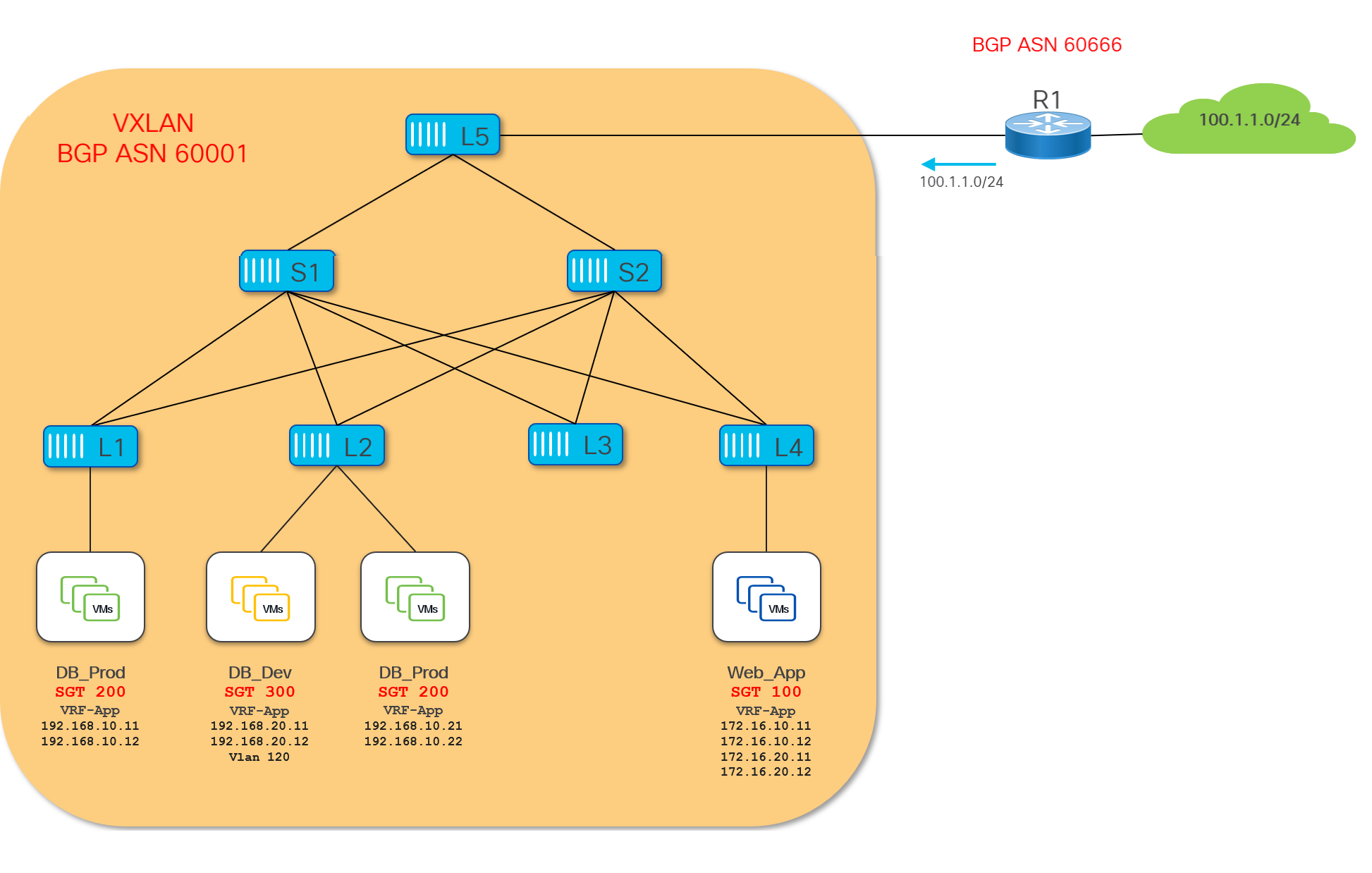
R1 is advertising the 100.1.1.0/24 prefix to border leaf L5, which in turn converts it to an EVPN Type-5 route that is advertised within the VXLAN fabric.
For clarity, this example shows just one external subnet (100.1.1.0/24) behind the external router R1, but in a real-world scenario there could be more than one VRF-Lite hand-offs and multiple external networks.
Since Border Leaf-5 is a new addition to this topology (the rest of the fabric has already been configured in previous sections), we need this device to be configured as a VTEP. The following sample shows the overlay tenant VRF configuration on L5 (other configuration has not been shown for brevity).
Overlay Tenant VRF configuration
Border Leaf-5:
interface loopback0
description Routing loopback interface
ip address 10.2.0.5/32 tag 54321
ip router ospf UNDERLAY area 0.0.0.0
ip pim sparse-mode
interface loopback1
description VTEP loopback interface
ip address 10.3.0.5/32 tag 54321
ip router ospf UNDERLAY area 0.0.0.0
ip pim sparse-mode
<snip>
vrf context VRF_App
vni 50000 l3
rd auto
address-family ipv4 unicast
route-target both auto
route-target both auto even
address-family ipv6 unicast
route-target both auto
route-target both auto evpn
interface nve1
no shutdown
host-reachability protocol bgp
source-interface loopback1
member vni 50000 associate-vrf
router bgp 65001
vrf VRF_App
address-family ipv4 unicast
advertise l2vpn evpn
redistribute direct route-map fabric-rmap-redist-subnet
maximum-paths ibgp 2
address-family ipv6 unicast
advertise l2vpn evpn
redistribute direct route-map fabric-rmap-redist-subnet
maximum-paths ibgp 2
The following sample shows the configuration required for the VRF-Lite handoff.
VRF-Lite Configuration
Border Leaf-5:
ip prefix-list default-route seq 5 permit 0.0.0.0/0 le 1
ip prefix-list host-route seq 5 permit 0.0.0.0/0 eq 32
ipv6 prefix-list default-route-v6 seq 5 permit 0::/0
ipv6 prefix-list host-route-v6 seq 5 permit 0::/0 eq 128
route-map extcon-rmap-filter deny 10
match ip address prefix-list default-route
route-map extcon-rmap-filter deny 20
match ip address prefix-list host-route
route-map extcon-rmap-filter permit 1000
route-map extcon-rmap-filter-allow-host deny 10
match ip address prefix-list default-route
route-map extcon-rmap-filter-allow-host permit 1000
route-map extcon-rmap-filter-v6 deny 10
match ipv6 address prefix-list default-route-v6
route-map extcon-rmap-filter-v6 deny 20
match ipv6 address prefix-list host-route-v6
route-map extcon-rmap-filter-v6 permit 1000
route-map extcon-rmap-filter-v6-allow-host deny 10
match ipv6 address prefix-list default-route-v6
route-map extcon-rmap-filter-v6-allow-host permit 1000
interface ethernet1/17
mtu 9216
description connected-to-External Router R1 Eth1/17
no switchport
negotiate auto
no shutdown
interface ethernet1/17.2
encapsulation dot1q 2
mtu 9216
vrf member VRF_App
ip address 10.33.0.2/30
no shutdown
router bgp 65001
vrf VRF_App
address-family ipv4 unicast
advertise l2vpn evpn
redistribute direct route-map fabric-rmap-redist-subnet
maximum-paths ibgp 2
exit
address-family ipv6 unicast
advertise l2vpn evpn
redistribute direct route-map fabric-rmap-redist-subnet
maximum-paths ibgp 2
exit
neighbor 10.33.0.1
remote-as 60666
address-family ipv4 unicast
send-community both
route-map extcon-rmap-filter out
External Router R1:
vrf context External_VRF
address-family ipv4 unicast
exit
router bgp 60666
vrf External_VRF
address-family ipv4 unicast
neighbor 10.33.0.2
remote-as 65001
address-family ipv4 unicast
send-community both
interface ethernet1/17
mtu 9216
description connected-to-VXLAN Border Leaf-5 Eth1/17
no switchport
negotiate auto
no shutdown
interface ethernet1/17.2
vrf member External_VRF
mtu 9216
encapsulation dot1q 2
ip address 10.33.0.1/30
no shutdown
Verification
The following output shows how Leaf-5 has received the 100.1.1.0/24 prefix from the External router:
Leaf5# show bgp ipv4 unicast vrf VRF_App
BGP routing table information for VRF VRF_App, address family IPv4 Unicast
BGP table version is 19, Local Router ID is 10.33.0.2
Status: s-suppressed, x-deleted, S-stale, d-dampened, h-history, *-valid, >-best
Path type: i-internal, e-external, c-confed, l-local, a-aggregate, r-redist, I-injected
Origin codes: i - IGP, e - EGP, ? - incomplete, | - multipath, & - backup, 2 - best2
Network Next Hop Metric LocPrf Weight Path
*>e100.1.1.0/24 10.33.0.1 0 60666 i
<snip>
Since Leaf-5 is the Border VETP, it generates a corresponding L2VPN EVPN route for this external prefix and advertises it to all the local VTEPs in the VXLAN fabric.
Leaf5# show bgp l2vpn evpn 100.1.1.0
BGP routing table information for VRF default, address family L2VPN EVPN
Route Distinguisher: 10.2.0.5:4 (L3VNI 50000)
BGP routing table entry for [5]:[0]:[0]:[24]:[100.1.1.0]/224, version 52
Paths: (1 available, best #1)
Flags: (0x000002) (high32 00000000) on xmit-list, is not in l2rib/evpn
Advertised path-id 1
Path type: local, path is valid, is best path, no labeled nexthop
Gateway IP: 0.0.0.0
AS-Path: 60666 , path sourced external to AS
10.3.0.5 (metric 0) from 0.0.0.0 (10.2.0.5)
Origin IGP, MED not set, localpref 100, weight 0
Received label 50000
Extcommunity: RT:65001:50000 ENCAP:8 PCTAG:0:0:500 Router MAC:481b.a4b0.7c8b
Path-id 1 advertised to peers:
10.2.0.4 10.2.0.6
Leaf5#
Configuration
The assumption is that L5 already has the GPO feature enabled and the VRF is set to enforced default-deny mode.
The first step of the GPO configuration is to create an SG and classify external networks as part of it.
Note: A new SG can be created for this purpose, or an already existing SG could also be used.
Create a new SG and classify the external prefix 100.1.1.0/24 received on the Border Leaf L5 as shown below.
Leaf-5:
security-group 500 name External_Net
match external-subnets vrf VRF_App ipv4 100.1.1.0/24
Note: In the above example, the /24 prefix length is used to match the external subnet. This statement is valid for matching the prefix 100.1.1.0/24 (exact match), as well as any more specific subnets with longer mask (prefix length) including host routes (/32). For example, if a host route 100.1.1.10/32 is received from the external network, it will also get classified to the same security group 500, as the specific prefix 100.1.1.10/32 is “covered” by the more generic 100.1.1.0/24 prefix.
Since the VRF is already set to default-deny mode, no communication can take place between the external network and the VXLAN fabric unless a permit contract is configured. Our requirement is to only allow inbound HTTPs traffic from the External SG to the Web_App SG, as shown below.
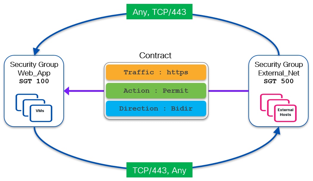
Configure the following class-map and policy-map to permit HTTPs traffic:
Leaf-5:
class-map type security match-any web_https
match ip tcp dport 443
policy-map type security permit_web_port-443
class web_https
permit
log
Now define a contract to allow HTTPs traffic originating from the External_Net (SGT 500) and destined to Web_App (SGT 100) endpoints in the VXLAN fabric. This can be achieved by defining a bidirectional contract allowing HTTPs requests originating from the external network and HTTPs responses from the VXLAN fabric.
Leaf-5:
vrf context VRF_App
security contract source 500 destination 100 policy permit_web_port-443 bidir
These policies and contracts also need to be deployed on all the VTEPs where we have Web_App SG configured (Leaf-4 in our example).
Leaf-4:
class-map type security match-any web_https
match ip tcp dport 443
policy-map type security permit_web_port-443
class web_https
permit
log
vrf context VRF_App
security contract source 500 destination 100 policy permit_web_port-443 bidir
Note: Leaf-4 has already been configured for VXLAN and GPO as part of the E-W use-case previously discussed.
The example above shows one prefix 100.1.1.0/24 received from the external network and a corresponding match statement being used. In real world scenarios, it is quite common to receive multiple prefixes and/or a single default route (0.0.0.0/0 prefix). In such scenarios, it may become operationally complex to define multiple match statements (one for each prefix received) unless there is a need to classify them to different SGs. A better solution is to use a match statement with 0.0.0.0/0 (match-all) that covers all the received prefixes including the default route 0/0 (if existing), resulting in a huge reduction of the match entries required.
Match statement with 0.0.0.0/0 is best suited when the same enforcement policy needs to be applied to all communication with the external network domain. But what if there is a requirement to apply different policies to different external destinations?
This would require using more specific match statements and classifying external routes to different SGs to assign unique SGTs to them then use those different SGTs in defining different contracts. Please note that this approach may result in lengthier configuration and increased operational complexity. Nonetheless, this solution works as long as those more specific external routes are received from the external network.
But what should be done when only a default route (0.0.0.0/0) is received from the external routers and different enforcement policies are required for external networks?
Let’s try to understand this problem with the help of the following diagram (Figure 57):
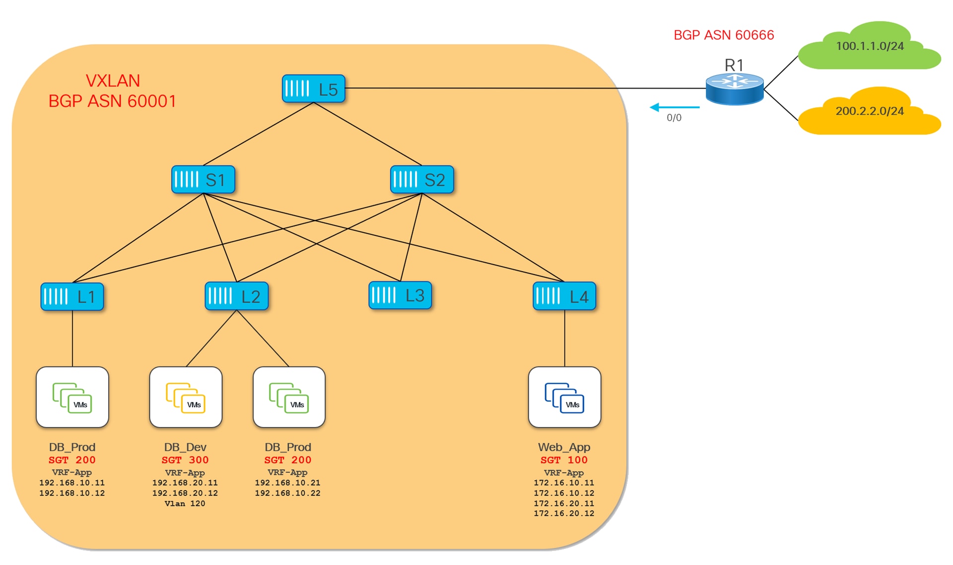
As shown in the diagram above, we have 100.1.1.0/24 and 200.2.2.0/24 external destinations but R1 is only advertising a 0.0.0.0/0 default route to the VXLAN fabric. Creating matching prefixes (100.1.1.0/24 and 200.2.2.0/24) to classify the two external networks would not work in this scenario, since those routes are not present in the VTEP’s routing table (remember, only the 0.0.0.0/0 is received from R1). Therefore, the only prefix that can be classified to a SG in this example is the default route but doing so will not allow to apply specific policies for communication with those networks.
Route-Inject Functionality
To address this challenge, specific functionality has been introduced in the NX-OS implementation. Starting from release 10.5(2), NX-OS has an option to inject routes carrying SG tags into the local fabric, based on the specific classification configuration applied to external networks.
In order to achieve this, a route-inject knob has been added to the match external-subnet CLI statement. This configuration causes a corresponding route to be locally generated on the Border Leaf to be advertised to the other VTEPs on the fabric. This “route injection” is happening as long as a “covering route” for that specific prefix is present in the routing table of the Border Leaf. Back to our example in Figure 57, the default route received from R1 can “cover” any more specific prefix used to classify external resources to specific SGs.
The following configuration snippet shows the route-inject functionality in action on Border Leaf-5 for the specific scenario previously depicted in Figure 57.
Before the route injection functionality can be enabled, a global command must be configured to specify a community value (AS:NN format) that gets attached to the injected route. Later this community value can be used for filtering this route if required, and this global command can therefore being used as a general point of control for the enablement of the route-inject functionality.
security-group external-subnets route-inject resolved community 65001:60666
After the global knob is enabled, it is then possible to use the route-inject knob along with match external-subnets statement for granular injection of the corresponding prefix into the fabric. In our specific example, the goal is to classify the two external prefixes 100.1.1.0/24 and 200.2.2.0/24 to two separate SGs (respectively SG 1100 and SG 2200).
Leaf-5:
security-group 500 name External_Net
match external-subnets vrf VRF_App ipv4 0.0.0.0/0
security-group 1100 name Ext_Net_100
match external-subnets vrf VRF_App ipv4 100.1.1.0/24 route-inject
security-group 2200 name Ext_Net_200
match external-subnets vrf VRF_App ipv4 200.2.2.0/24 route-inject
Note: In the above example, classifying default route (0/0) to a SG is completely optional when route-inject keyword is used with more specific external prefixes. However, it may be useful in cases where only few external networks require a different enforcement policy to be applied (prefixes for those networks are classified with route-inject keyword), while the rest of the external networks (classified to SG 500 because of the covering 0/0 prefix match statement) have the same policy enforcement.
As a result of the configuration above, which must only be applied to the Border Leaf node, we see now that Leaf-5 has generated and stored in the BGP table routes for the networks 100.1.1.0/24 and 200.2.2.0/24. Looking at the weight (32768) and next-hop (0.0.0.0) values for these routes, it’s evident they have been locally generated on Leaf-5.
Leaf5# show bgp ipv4 unicast vrf VRF_App
BGP routing table information for VRF VRF_App, address family IPv4 Unicast
BGP table version is 107, Local Router ID is 10.33.0.2
Status: s-suppressed, x-deleted, S-stale, d-dampened, h-history, *-valid, >-best
Path type: i-internal, e-external, c-confed, l-local, a-aggregate, r-redist, I-injected
Origin codes: i - IGP, e - EGP, ? - incomplete, | - multipath, & - backup, 2 - best2
Network Next Hop Metric LocPrf Weight Path
<snip>
*>r100.1.1.0/24 0.0.0.0 0 10 32768 ?
<snip>
*>r200.2.2.0/24 0.0.0.0 0 10 32768 ?
<snip>
Leaf5#
Leaf5# show bgp ipv4 unicast 100.1.1.0 vrf VRF_App
BGP routing table information for VRF VRF_App, address family IPv4 Unicast
BGP routing table entry for 100.1.1.0/24, version 125
Paths: (1 available, best #1)
Flags: (0x80c0002) (high32 0x000020) on xmit-list, is not in urib, exported
vpn: version 133, (0x00000000100002) on xmit-list
Multipath: iBGP
Advertised path-id 1, VPN AF advertised path-id 1
Path type: redist, path is valid, is best path, no labeled nexthop, is extd
AS-Path: NONE, path locally originated
0.0.0.0 (metric 0) from 0.0.0.0 (10.33.0.2)
Origin incomplete, MED 0, localpref 10, weight 32768
Community: 65001:60666
Extcommunity: RT:65001:50000 PCTAG:0:0:1100
VRF advertise information:
Path-id 1 advertised to peers:
10.33.0.1
VPN AF advertise information:
Path-id 1 not advertised to any peer
Leaf5# show security-group id all
Security Group ID 500 , Name External_Net
Selector Type : External IPv4 Subnets
VRF-Name IPv4-Address/mask-len
VRF_App 0.0.0.0/0
Security Group ID 1100 , Name Ext_Net_100
Selector Type : External IPv4 Subnets
VRF-Name IPv4-Address/mask-len
VRF_App 100.1.1.0/24
Security Group ID 2200 , Name Ext_Net_200
Selector Type : External IPv4 Subnets
VRF-Name IPv4-Address/mask-len
VRF_App 200.2.2.0/24
Leaf5#
The following output shows the corresponding Type-5 routes originated for external prefixes 100.1.1.0/24 & 200.2.2.0/24 by Leaf-5 along with their respective SGTs (PCTAG) 1100 and 2200 and advertised internally to the VXLAN fabric:
Leaf5# show bgp l2vpn evpn 100.1.1.0
BGP routing table information for VRF default, address family L2VPN EVPN
Route Distinguisher: 10.2.0.5:4 (L3VNI 50000)
BGP routing table entry for [5]:[0]:[0]:[24]:[100.1.1.0]/224, version 166
Paths: (1 available, best #1)
Flags: (0x000002) (high32 00000000) on xmit-list, is not in l2rib/evpn
Advertised path-id 1
Path type: local, path is valid, is best path, no labeled nexthop
Gateway IP: 0.0.0.0
AS-Path: NONE, path locally originated
10.3.0.5 (metric 0) from 0.0.0.0 (10.2.0.5)
Origin incomplete, MED 0, localpref 10, weight 32768
Received label 50000
Community: 65001:60666
Extcommunity: RT:65001:50000 ENCAP:8 PCTAG:0:0:1100 Router MAC:481b.a4b0.7c8b
Path-id 1 advertised to peers:
10.2.0.11 10.2.0.12
Leaf5# show bgp l2vpn evpn 200.2.2.0
BGP routing table information for VRF default, address family L2VPN EVPN
Route Distinguisher: 10.2.0.5:4 (L3VNI 50000)
BGP routing table entry for [5]:[0]:[0]:[24]:[200.2.2.0]/224, version 168
Paths: (1 available, best #1)
Flags: (0x000002) (high32 00000000) on xmit-list, is not in l2rib/evpn
Advertised path-id 1
Path type: local, path is valid, is best path, no labeled nexthop
Gateway IP: 0.0.0.0
AS-Path: NONE, path locally originated
10.3.0.5 (metric 0) from 0.0.0.0 (10.2.0.5)
Origin incomplete, MED 0, localpref 10, weight 32768
Received label 50000
Community: 65001:60666
Extcommunity: RT:65001:50000 ENCAP:8 PCTAG:0:0:2200 Router MAC:481b.a4b0.7c8b
Path-id 1 advertised to peers:
10.2.0.11 10.2.0.12
Leaf5#
Those external routes are received with their respective SGTs and installed in the routing table of the local leaf nodes:
Leaf4# show ip route 100.1.1.0/24 detail vrf VRF_App
IP Route Table for VRF "VRF_App"
'*' denotes best ucast next-hop
'**' denotes best mcast next-hop
'[x/y]' denotes [preference/metric]
'%<string>' in via output denotes VRF <string>
100.1.1.0/24, ubest/mbest: 1/0
*via 10.3.0.5%default, [200/0], 00:00:55, bgp-65001, internal, tag 65001, segid: 50000 tunnelid: 0xa030005 encap: VXLAN
BGP-EVPN: VNI=50000 (EVPN)
client-specific data: f0
recursive next hop: 10.3.0.5/32%default
xri tag type: Security Group; value: 1100
Leaf4#
Leaf4# show ip route 200.2.2.0/24 detail vrf VRF_App
IP Route Table for VRF "VRF_App"
'*' denotes best ucast next-hop
'**' denotes best mcast next-hop
'[x/y]' denotes [preference/metric]
'%<string>' in via output denotes VRF <string>
200.2.2.0/24, ubest/mbest: 1/0
*via 10.3.0.5%default, [200/0], 00:01:06, bgp-65001, internal, tag 65001, segid: 50000 tunnelid: 0xa030005 encap: VXLAN
BGP-EVPN: VNI=50000 (EVPN)
client-specific data: f1
recursive next hop: 10.3.0.5/32%default
xri tag type: Security Group; value: 2200
Leaf4#
Since these external prefixes are mapped to different SGTs, this enables defining and enforcing different security policies for the north-south communication with those external prefixes.
For example, as shown in Figure 58, we want to allow HTTPs traffic between Web-App SG and external network 100.1.1.0/24, whereas HTTPs traffic between DB_Prod and external network 200.1.1.0/24 must be inspected by the firewall as show below:
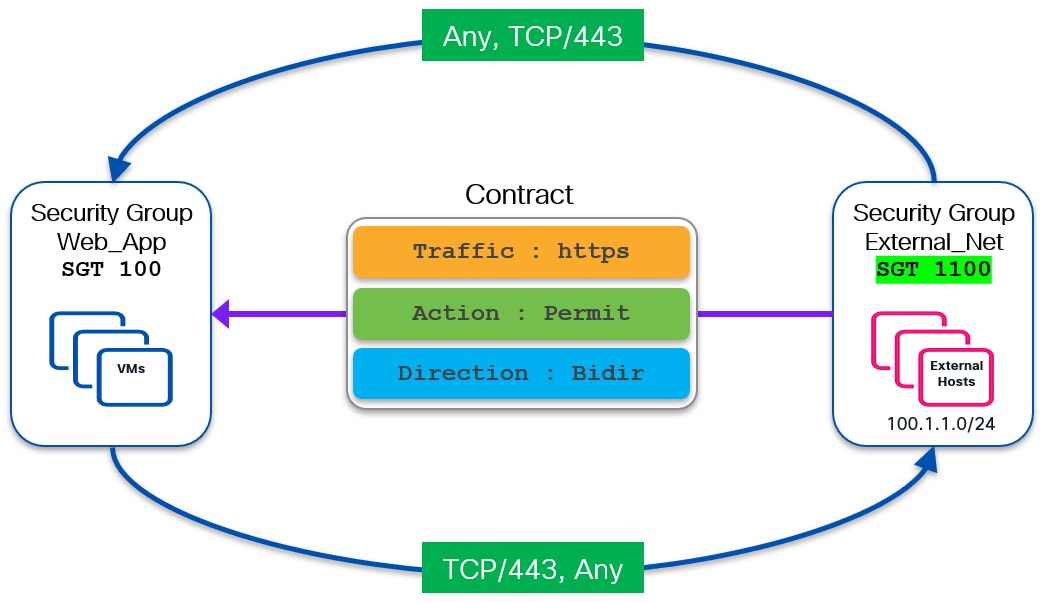
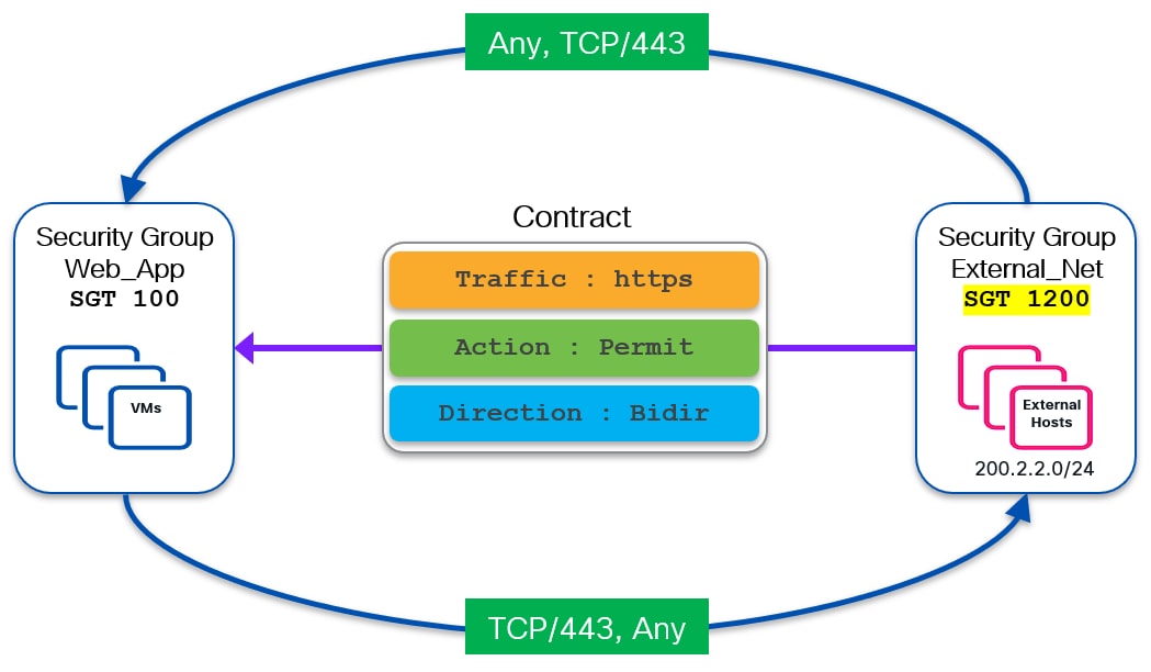
An SGACL (contract) to permit HTTPs traffic has already been discussed and configured previously. The next section discusses the GPO based redirection use-case.
As mentioned in the previous use case, VXLAN GPO can also be used for redirecting traffic to a Service Device (FW, SLB, IPS, etc.) or to a chain of service devices. GPO based service redirection provides better granularity and flexibility when compared to traditional ePBR based redirection (which mandated to use IP addresses to determine what flows to redirect). In addition, it is more scalable making it a suitable option for large scale service redirection deployments. This document only mentions redirection to a single one-arm service node however, both one-arm and two-arm deployments are supported and up to five service nodes can be added in a single service chain.
Let’s understand GPO based redirection with the following topology:
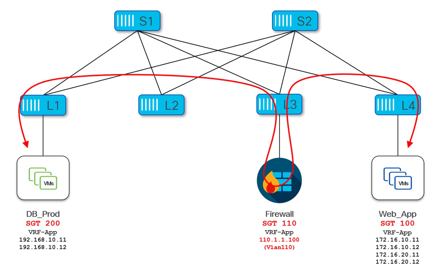
For example, our requirement is to redirect to a firewall function the HTTPs traffic between the source SG DB_Prod and the destination SG Web_App. Once the traffic is received by the firewall, it will inspect it and permit it (or drop it) depending on the specific security policies defined on the firewall. The SGACL contract for this redirection is shown in Figure 61:
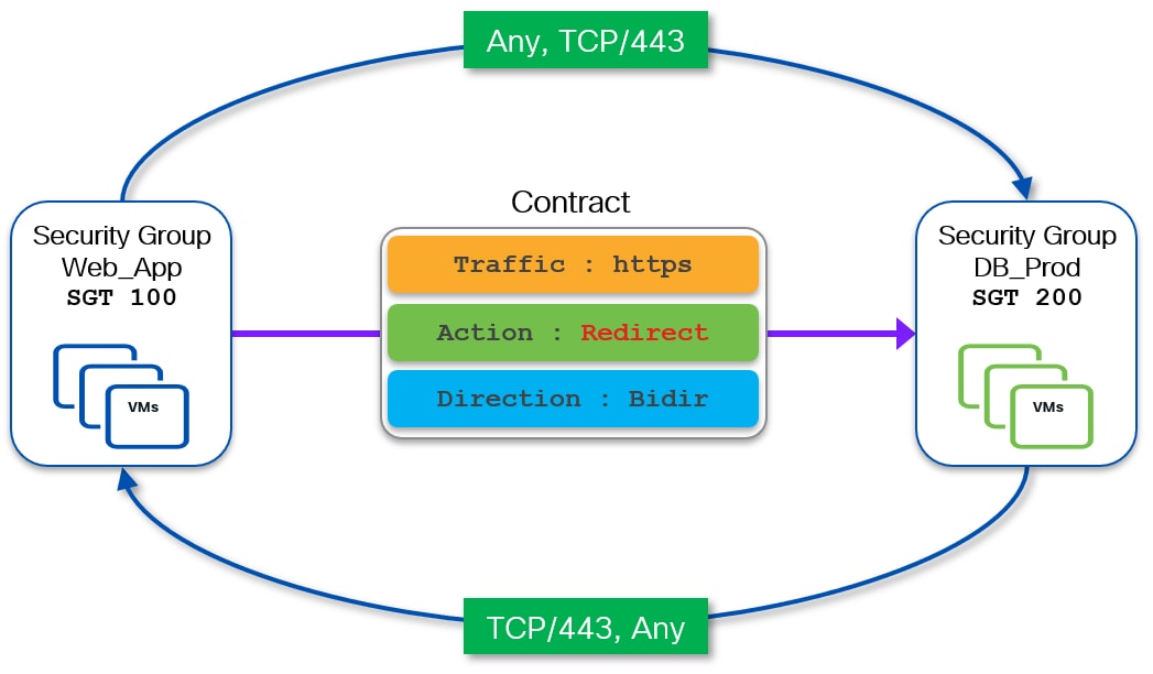
Figure 62 shows the data-plane operation for this redirection between a source endpoint 192.168.10.11 (part of SGT 200) and a destination endpoint 172.16.10.11 (part of SGT 100):
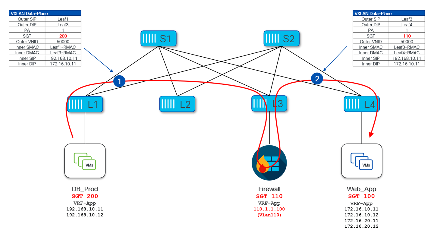
Let’s assume this fabric is pre-configured with all the necessary VXLAN, GPO and ePBR configuration. The source VTEP leaf-1 receives a packet from endpoint 192.168.10.11 (SGT 200) destined to the endpoint 172.16.10.11 (SGT 100) connected to leaf-4. Since a contract has been created to redirect traffic between those groups to the IP address of the firewall (100.1.1.100), Leaf-1 encapsulates this packet and sends it to the destination VTEP leaf-3 by setting inside the VXLAN header the Policy Applied bit and the SGT of the source (200).
Upon receiving this packet, leaf-3 strips off the VXLAN header and send the original packet to the firewall for inspection. Once the firewall returns this packet to the fabric, leaf-3 encapsulates it and sends it to destination VETP leaf-4 after setting in the VXLAN header the Policy Applied bit and the SGT value of the firewall that is 110.
A similar behavior is exhibited for the return traffic flow between endpoint 172.16.10.11 (SGT 100) and endpoint 192.168.10.11 (SGT 200), ensuring that the firewall can inspect both legs of the communication.
Configuration
As seen in the topology, the firewall is connected to service Leaf-3 using VLAN 110 (DAG 110.1.1.1/24). The following configuration snippet shows the VXLAN configuration required on the service Leaf-3:
Leaf-3:
vlan 110
vn-segment 110
interface Vlan110
no shutdown
vrf member VRF_App
ip address 110.1.1.1/24
fabric forwarding mode anycast-gateway
interface nve1
no shutdown
host-reachability protocol bgp
source-interface loopback1
member vni 110
mcast-group 239.1.1.1
member vni 50000 associate-vrf
Just like regular endpoints are mapped to SGs, the Service nodes (a firewall in this specific example) also needs to be mapped to its dedicated SG and assigned a unique SGT. The Security group SG_One_Arm_Fw is created on Leaf-3 with SGT 110 for this purpose:
Leaf-3:
security-group 110 name SG_One_Arm_Fw
type layer4-7
match interface Vlan110
Leaf3# show security-group type layer4-7
Security Group ID 110 , Name SG_One_Arm_Fw, Type Layer4-7 Service
Selector Type : Interface
Interface
Vlan110
Note: If there are multiple service nodes in the VXLAN fabric, a service VLAN and a service security group has to be defined on all the service leafs where the service nodes are connected.
Unlike internal endpoints and external prefixes, the classification of services nodes is done using the match interface keyword under type layer4-7, which only matches SVIs. Therefore, service nodes need to be placed in one (or more) dedicated VLANs exclusively used for connectivity with the service nodes.
Now let’s move to the ePBR configuration part with the ePBR service and service chain definitions.
First of all, a loopback interface is created on Leaf-3 to monitor the health of the firewall and take necessary actions whenever the firewall become unhealthy. Obviously, this is useful if a given firewall function is implemented using multiple FW nodes (each with its own IP address), so that traffic originally redirected to node 1 could be steered to node 2 when node 1 fails.
Leaf-3:
interface loopback11
description SLA Probe loopback interface
vrf member VRF_App
ip address 10.11.0.3/32 tag 12345
Activate the sla sender feature for monitoring the health of the service node and the pbr, epbr features for service definition:
feature sla sender
feature pbr
feature epbr
The following configuration snippet shows an ePBR service One_Arm_Fw that defines the IP of the firewall (110.1.1.100) and its binding with the SGT defined earlier. Also, defining the probe to monitor the health of the firewall.
Once the ePBR service is defined, the service chain construct of NX-OS is used to group multiple services together as well as fail-action:
Leaf-3:
epbr service SRV_One_Arm_Fw
vrf VRF_App
security-group 110
probe icmp source-interface loopback11
service-end-point ip 110.1.1.100
epbr service-chain SRV_Chain_One_Arm_Fw
10 set service SRV_One_Arm_Fw
Leaf3# show epbr service
<snip>
Name Type Service mode VRF
==========================================================================================
SRV_One_Arm_Fw L3 Full VRF_App
Security-group Reverse security-group Threshold
=======================================================
110
Endpoint IP/Intf Track SLA Op-ST Probe Hold-down Role Weight
Reverse IP/Intf Track SLA Op-ST Probe
==========================================================================================
110.1.1.100/ 1 20001 UP ICMP/0/0/0/0 A 1 Leaf3#
Leaf3# show epbr service-chain
Service-chain : SRV_Chain_One_Arm_Fw state:UP
service:SRV_One_Arm_Fw, sequence:10, fail-action:Drop
load-balance:Source-Destination-ipprotocol, action:Redirect
state:UP
IP 110.1.1.100 track 1 [UP]
Leaf3#
Now we are ready to configure the redirection using GPO. SG class-map is used to define interesting traffic for the redirection while SG policy-map defines the redirect action calling the GPO based ePBR service chain defined previously.
And finally using this policy-map, define the SGACL contract to redirect all the HTTPs traffic between the source and destination SGTs under the VRF:
Leaf-3:
class-map type security match-any web_https
match ip tcp dport 443
policy-map type security HTTPs_Redirect_To_Fw
class web_https
log
service-chain SRV_Chain_One_Arm_Fw
vrf context VRF_App
security contract source 100 destination 200 policy HTTPs_Redirect_To_Fw
security enforce tag 9999 default deny
Leaf3# show contracts detail
VRF: VRF_App
Contract source group 100 dest group 200
Policy: HTTPs_Redirect_To_Fw Direction: bidir
Stats: 0
Class: web_https
match ip tcp dport 443
Action: redir-SRV_Chain_One_Arm_Fw,log
OperSt: enabled
Leaf3#
Configuration on Compute Leafs
Create loopbacks on the compute leaf nodes for SLA probes –
Leaf-1:
interface loopback11
description SLA Probe loopback interface
vrf member VRF_App
ip address 10.11.0.1/32 tag 12345
Leaf-4:
interface loopback11
description SLA Probe loopback interface
vrf member VRF_App
ip address 10.11.0.4/32 tag 12345
Note that SG configuration on the compute leaf nodes is skipped here as they already have SGs Web_App and DB_Prod created during East-West Policy enforcement use-case discussed earlier:
Leaf1# show security-group id all
Security Group ID 200 , Name DB_Prod
Selector Type : Connected IPv4 Endpoints
VRF-Name IPv4-Address/mask-len
VRF_App 192.168.10.11/32
VRF_App 192.168.10.12/32
Leaf1#
Leaf4# show security-group id all
Security Group ID 100 , Name Web_App
Selector Type : Connected IPv4 Endpoints
VRF-Name IPv4-Address/mask-len
VRF_App 172.16.10.11/32
VRF_App 172.16.20.11/32
VRF_App 172.16.10.12/32
VRF_App 172.16.20.12/32
Leaf4#
security-group 100 name Web_App
match connected-endpoints vrf VRF_App ipv4 172.16.10.11/32
match connected-endpoints vrf VRF_App ipv4 172.16.10.12/32
match connected-endpoints vrf VRF_App ipv4 172.16.20.11/32
match connected-endpoints vrf VRF_App ipv4 172.16.20.12/32
Define ePBR Service
Leaf-1 and 4:
feature sla sender
feature epbr
epbr service SRV_One_Arm_Fw
vrf VRF_App
security-group 110
probe icmp source-interface loopback11
service-end-point ip 110.1.1.100
epbr service-chain SRV_Chain_One_Arm_Fw
10 set service SRV_One_Arm_Fw
Define redirect policy-map and SGACL contract for redirection:
Leaf-1 and 4:
class-map type security match-any web_https
match ip tcp dport 443
policy-map type security HTTPs_Redirect_To_Fw
class web_https
log
service-chain SRV_Chain_One_Arm_Fw
vrf context VRF_App
security contract source 100 destination 200 policy HTTPs_Redirect_To_Fw
security enforce tag 9999 default deny
Note: The above configuration steps must be followed on all the compute leaf nodes where Web_App and DB_Prod SGs are present.
This section explains the best practices with respect to VXLAN GPO deployments.
VXLAN GPO provides policy enforcement at fabric level due to its ability to carry SGT and signal the egress VTEP whether policy has been enforced on the ingress VTEP or not. Therefore, whenever GPO based policy enforcement is enabled, it must be enabled on all the devices within a fabric. Mix of devices with GPO enabled and GPO non-enabled devices within same fabric is not supported. However, in the case of Multi-Site you can mix Policy-Aware and Policy-Unaware sites within the same Multi-Site domain.
GPO policy enforcement only comes into effect when a VRF is set to enforcement mode which allows a specific tenant vrf to be enabled for GPO based policy enforcement while other tenant VRFs remain in unenforced mode. Whenever a VRF is set to enforced mode either default-permit or default-deny, it has to be consistently provisioned across all the devices within a fabric and all the sites in case of Policy-Aware Multi-Site domain.
Automation using Nexus Dashboard
Nexus Dashboard is the comprehensive management solution for Data Center networks powered by Cisco. Being a multi-fabric controller, Nexus Dashboard manages multiple deployment models such as VXLAN EVPN, Classic 3-tier and Routed-based fabrics for LAN while providing ready-to-use control, management, monitoring, and automation capabilities for all these environments.
The new Unified Nexus Dashboard 4.1 brings together different applications Fabric Controller (formally known as NDFC), Insights (NDI) and Orchestrator (NDO) and offering them as native services of Nexus Dashboard. This allows complete Day0-2 operations and management tasks for Data Center fabrics to be performed from a single console.
This section explains the workflow on Nexus Dashboard 4.1 to configure GPO based network segmentation based on following example:
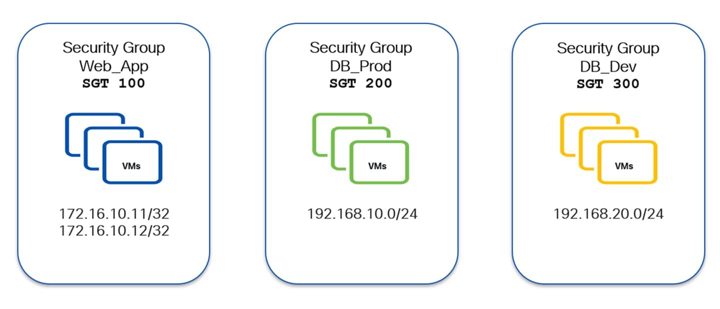
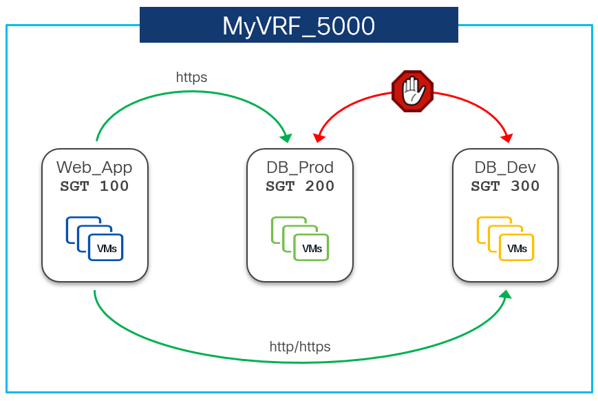
Procedure
Step 1. Create a VXLAN fabric and choose the Configuration mode as Advanced:
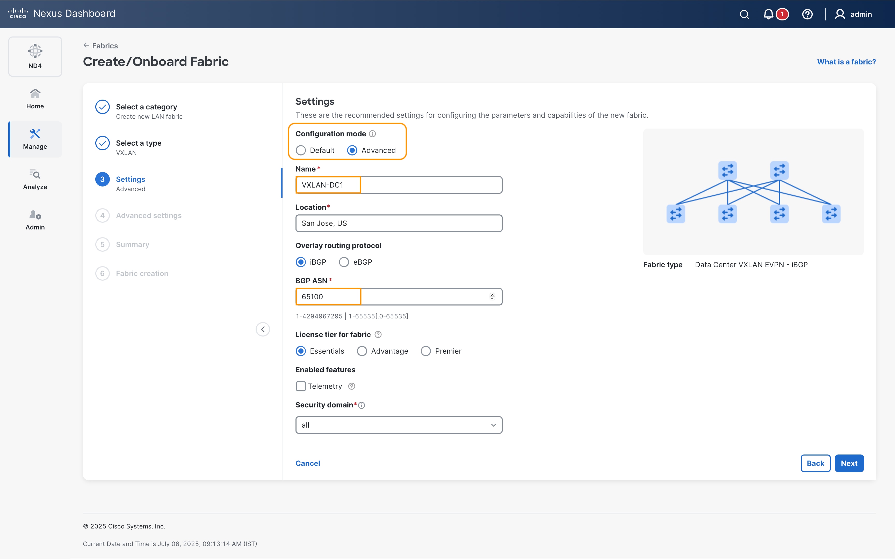
Step 2. To enable GPO based segmentation, click on Enable Security Groups check box under the Security tab of VXLAN fabric template:
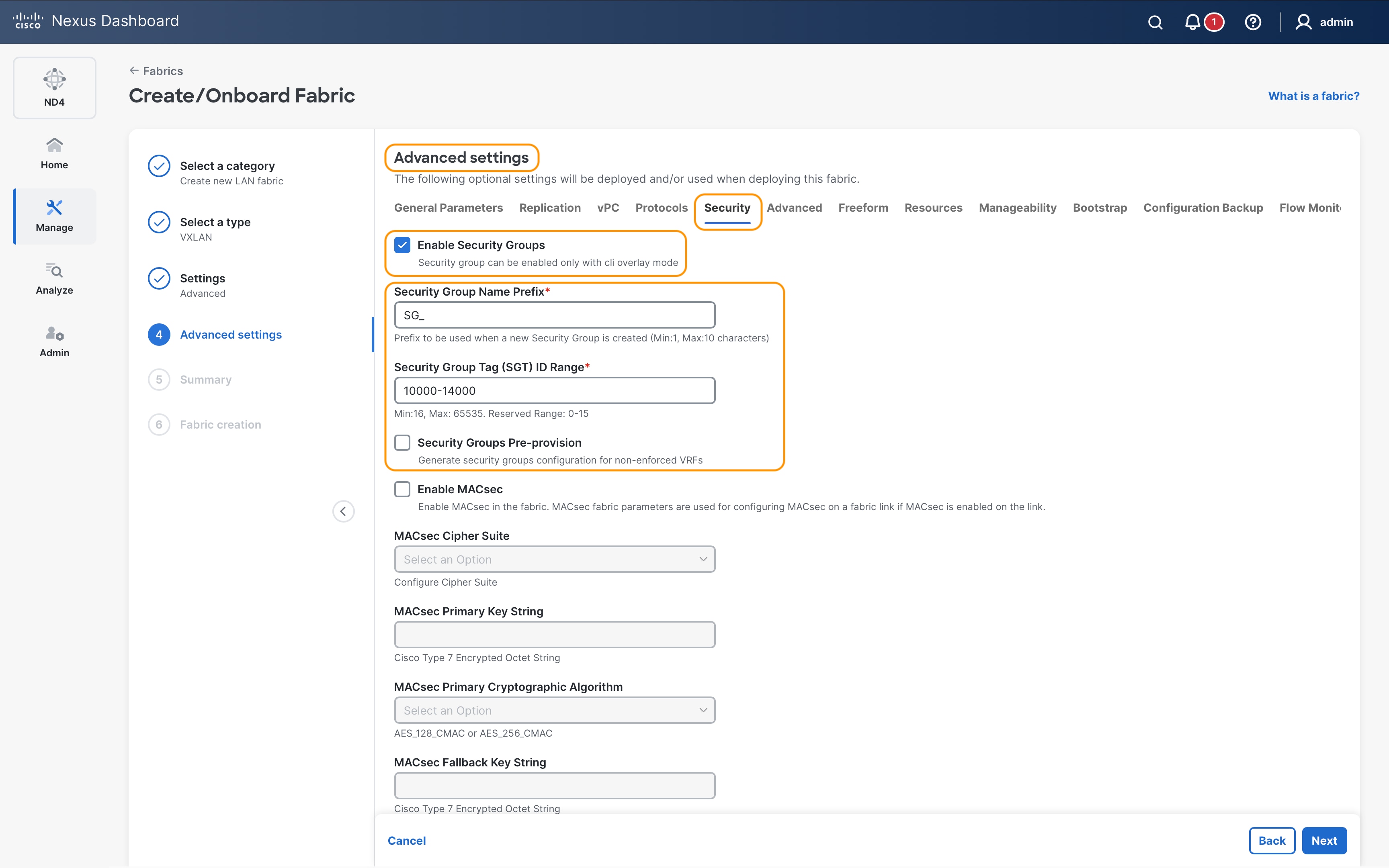
Optionally, other Security Group parameters can also be changed such as SG Name Prefix and SG Tag range.
Step 3. Review the settings in the other tabs of the fabric template and proceed with creation of the fabric.
Step 4. Once fabric is created, add the switches to the fabric and assign device roles and perform Recalculate & Deploy.
As seen in the screenshot Figure 67, NDFC is pushing the following highlighted configuration to all the leafs in the fabric to change routing mode to Security Group and activate the feature:
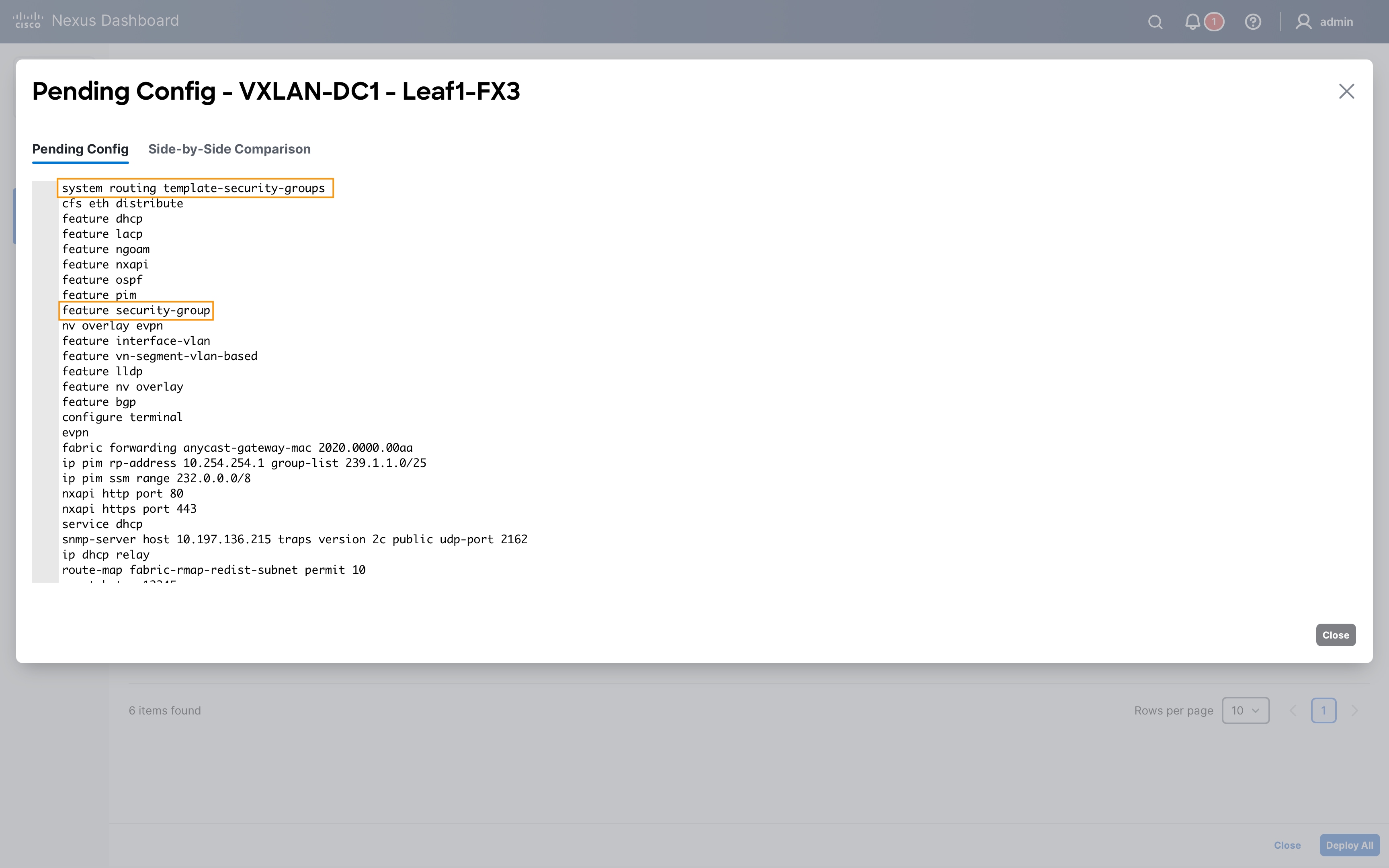
Step 5. Reload is required for the leaf switches for routing mode change to take effect:
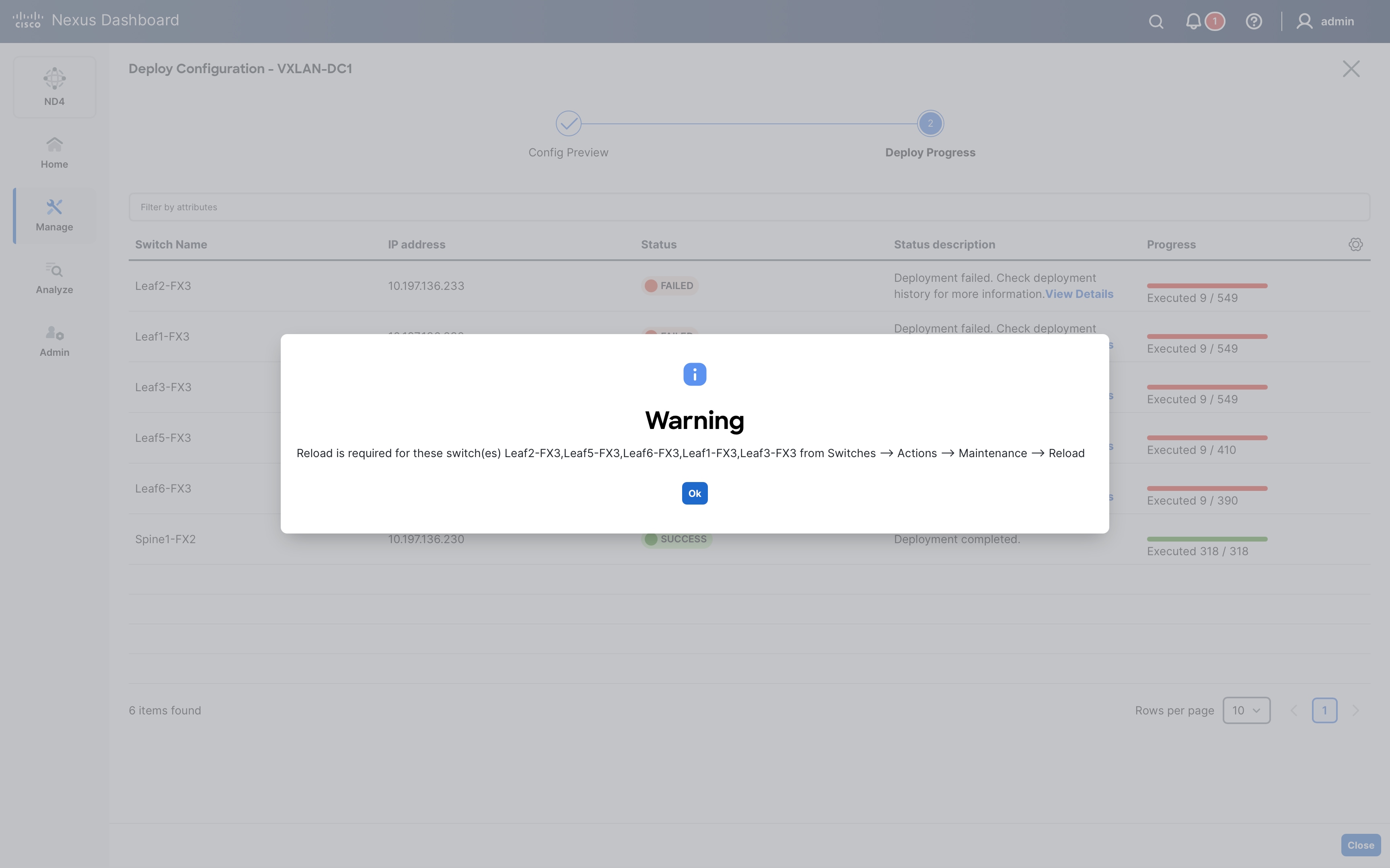
Select all the leaf switches and click on Reload from Actions > Maintenance > Reload and click on Confirm on the warning dialogue:
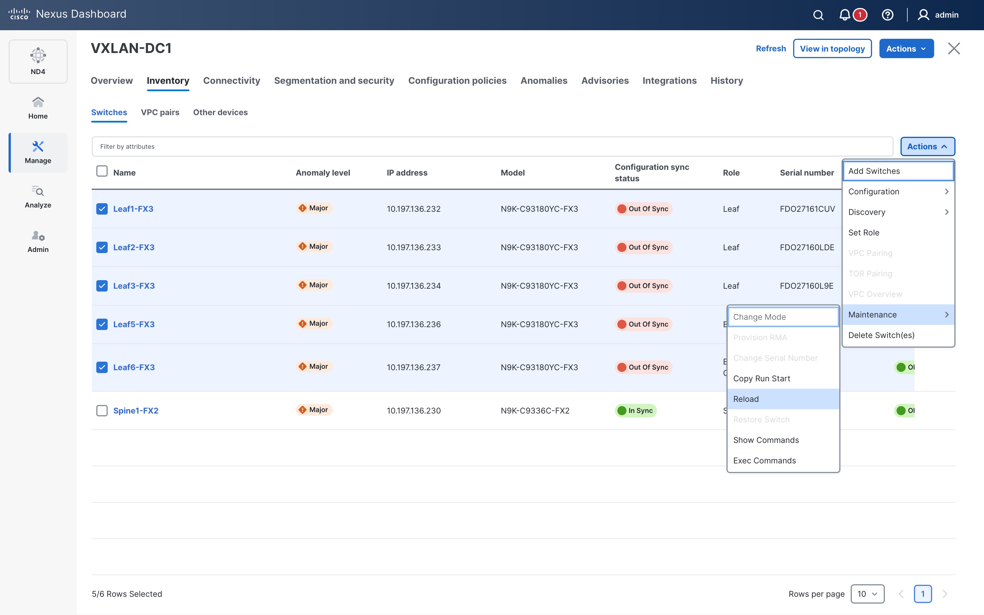
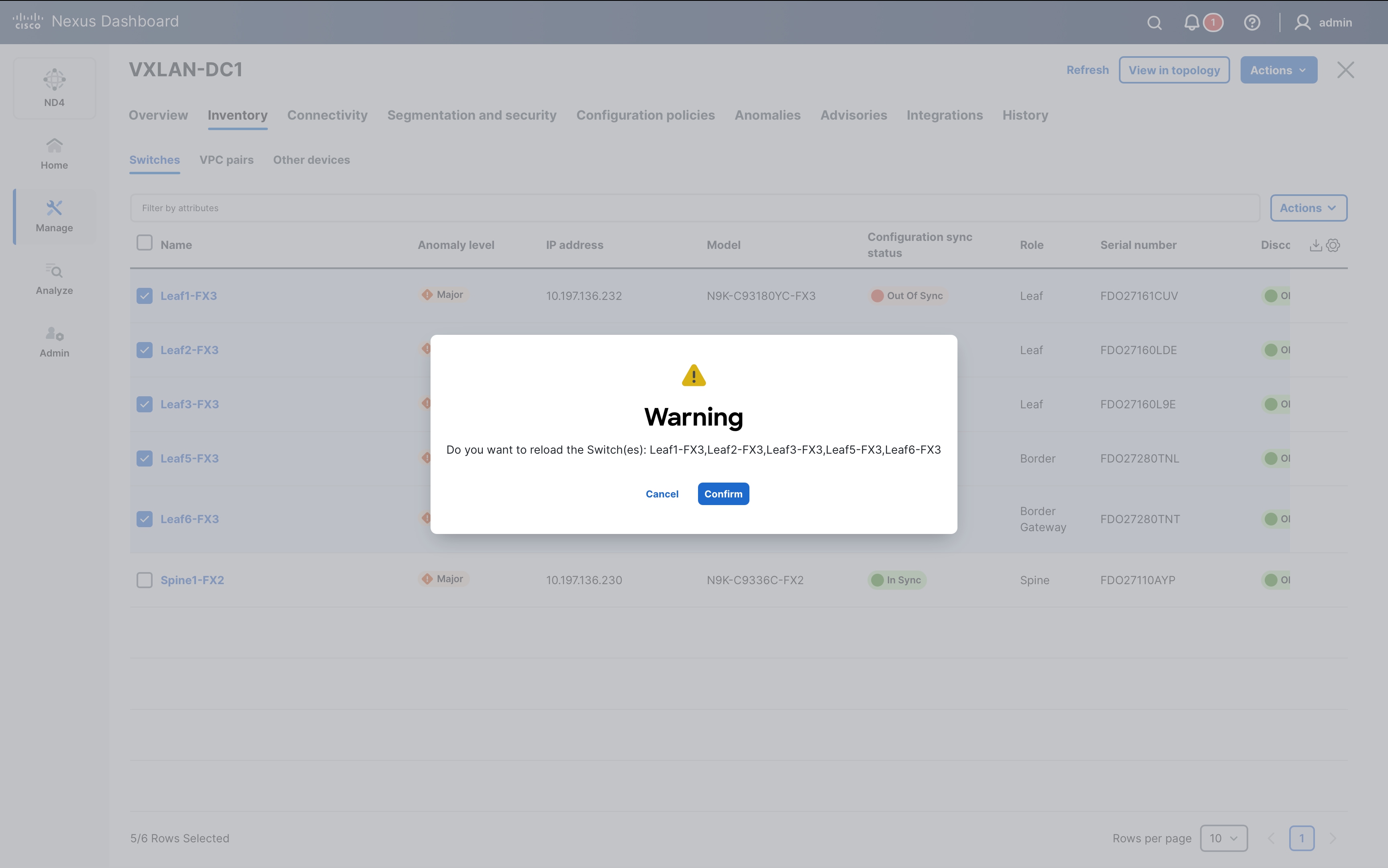
Step 6. The next day-0 task is to create VRF and Networks and deploy them.
To create the Tenant VRF, go to Segmentation and Security > VRFs tab and click Actions > Create.
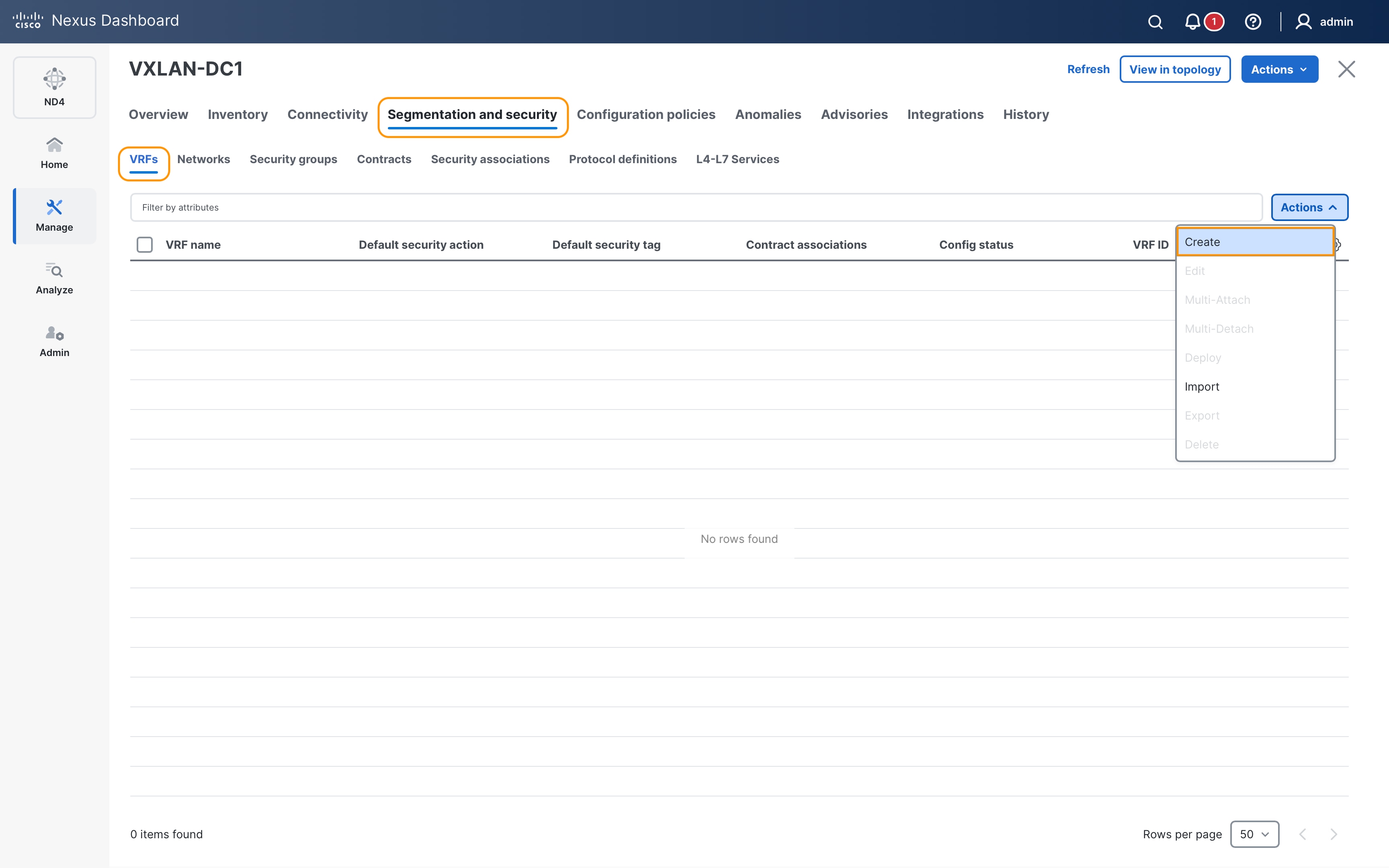
The first step to enable GPO based segmentation is to change the VRF mode to either Enforced Permit or Enforced Deny and specify the Default SGT for the VRF.
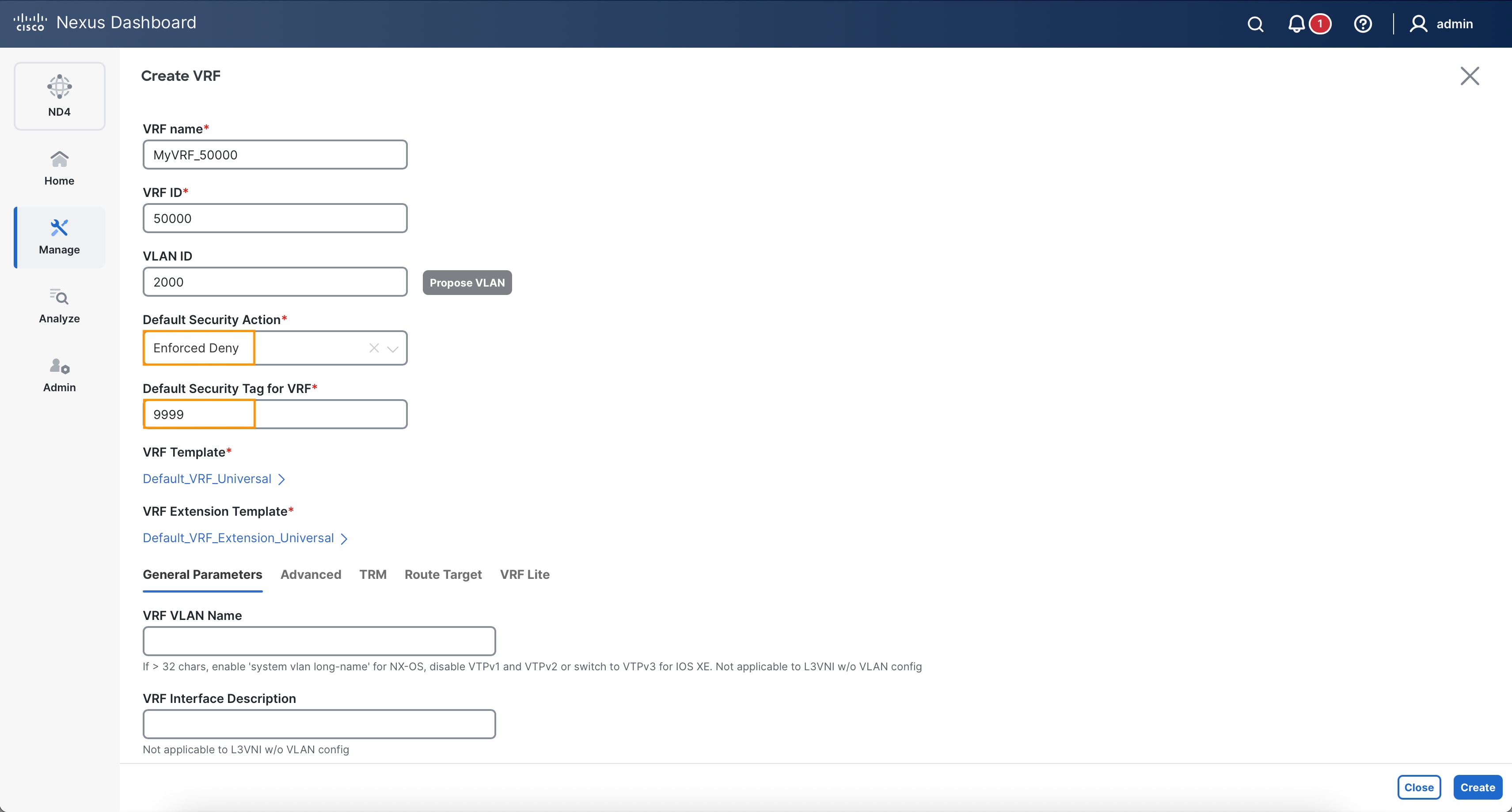
Notice how the default VRF mode is Unenforced and other modes available:
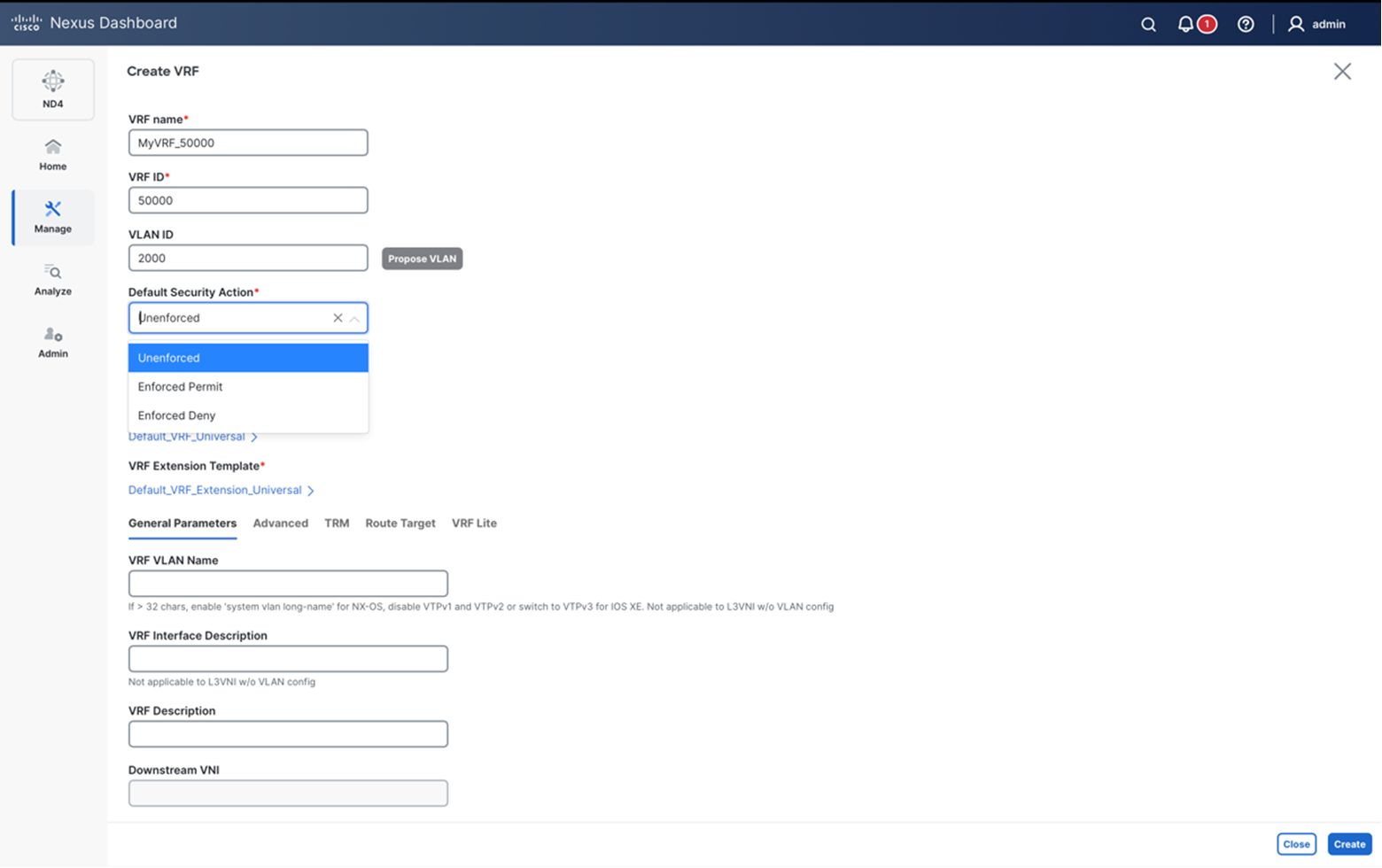
Once a VRF is created, the VRF mode, the default VRF SGT and any SG Contract associations can be verified from the VRF page:
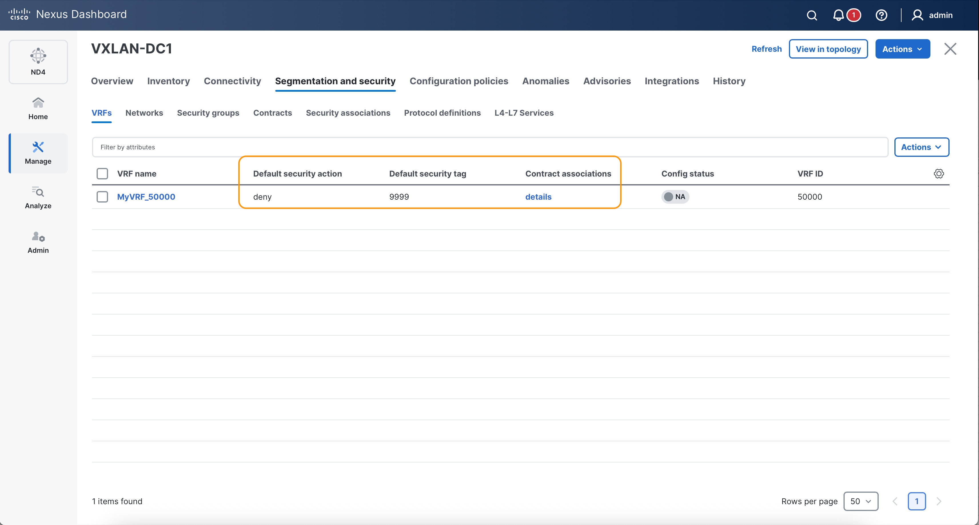
Next, create the networks and provision them on the leaf nodes (and interfaces) where they are required:
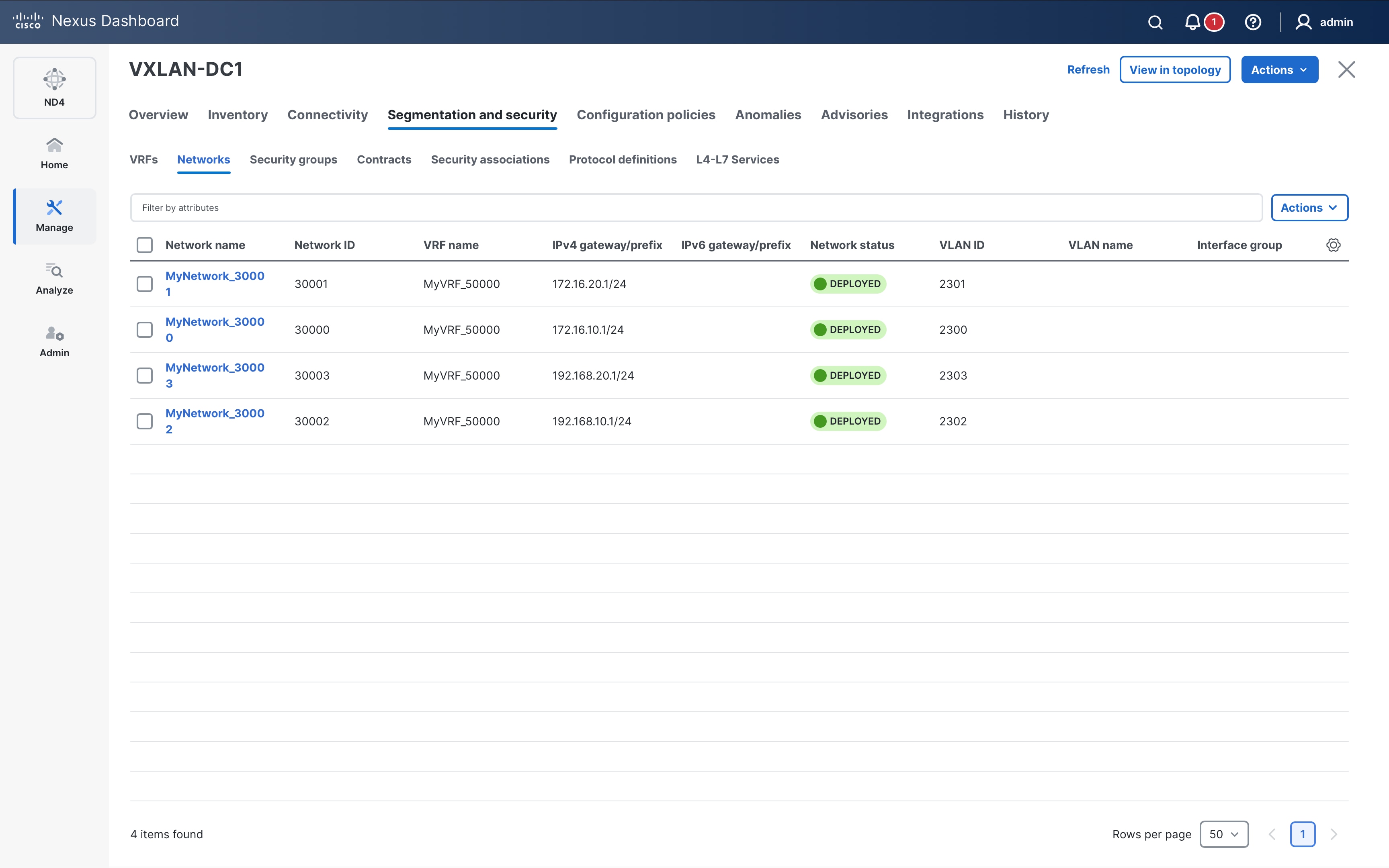
Step 7. Now move the Security groups tab and start creating the Security Groups (SG):
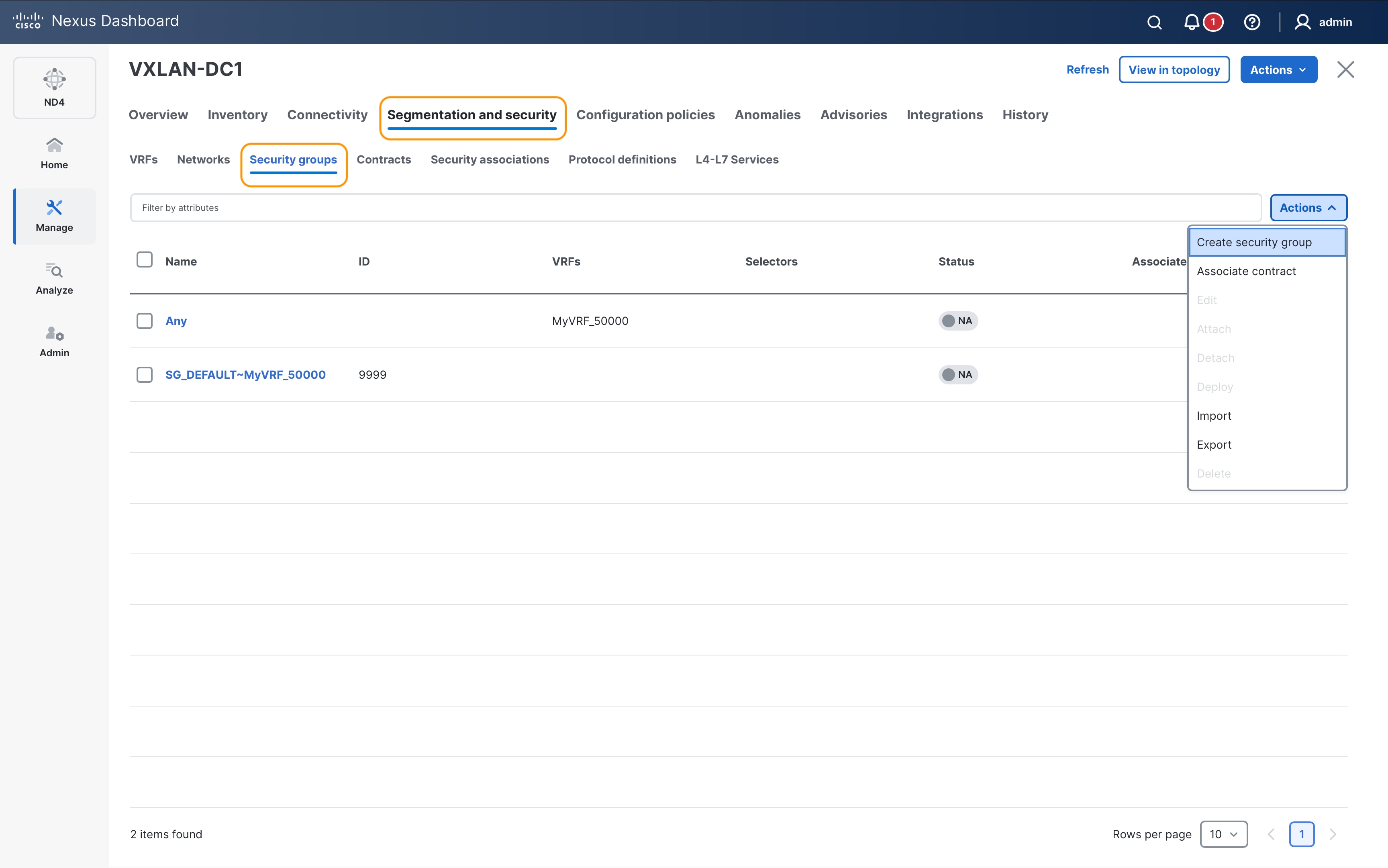
Create a Security Group (SG) Web_App for the endpoints 172.16.10.11 & 172.16.10.12 using IP Selectors:
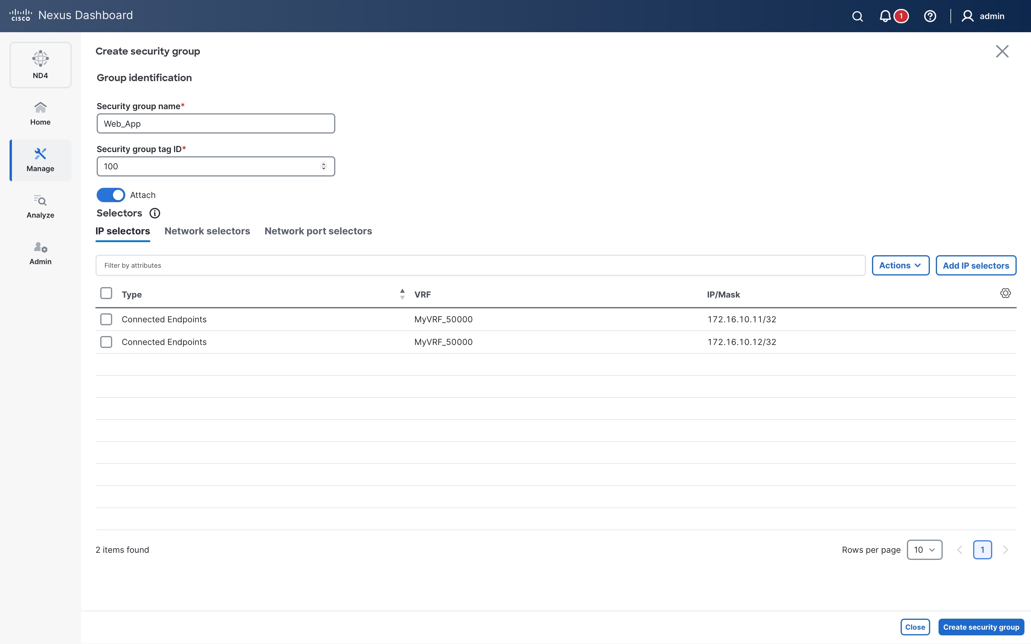
Similarly, create SGs for DB_Prod and DB_Dev using IP selectors:

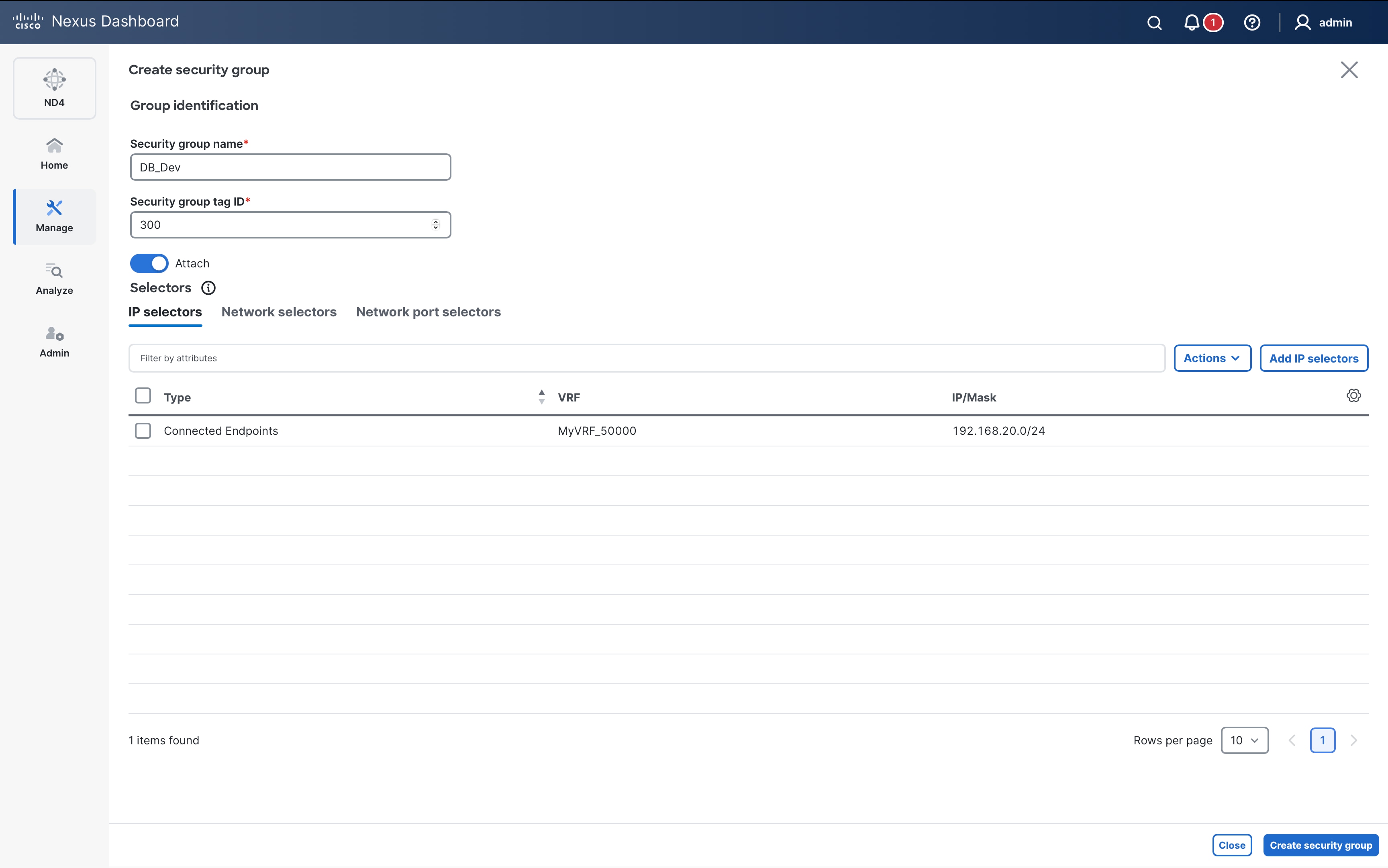
We now have 3 user-defined SGs created as shown in Figure 80:
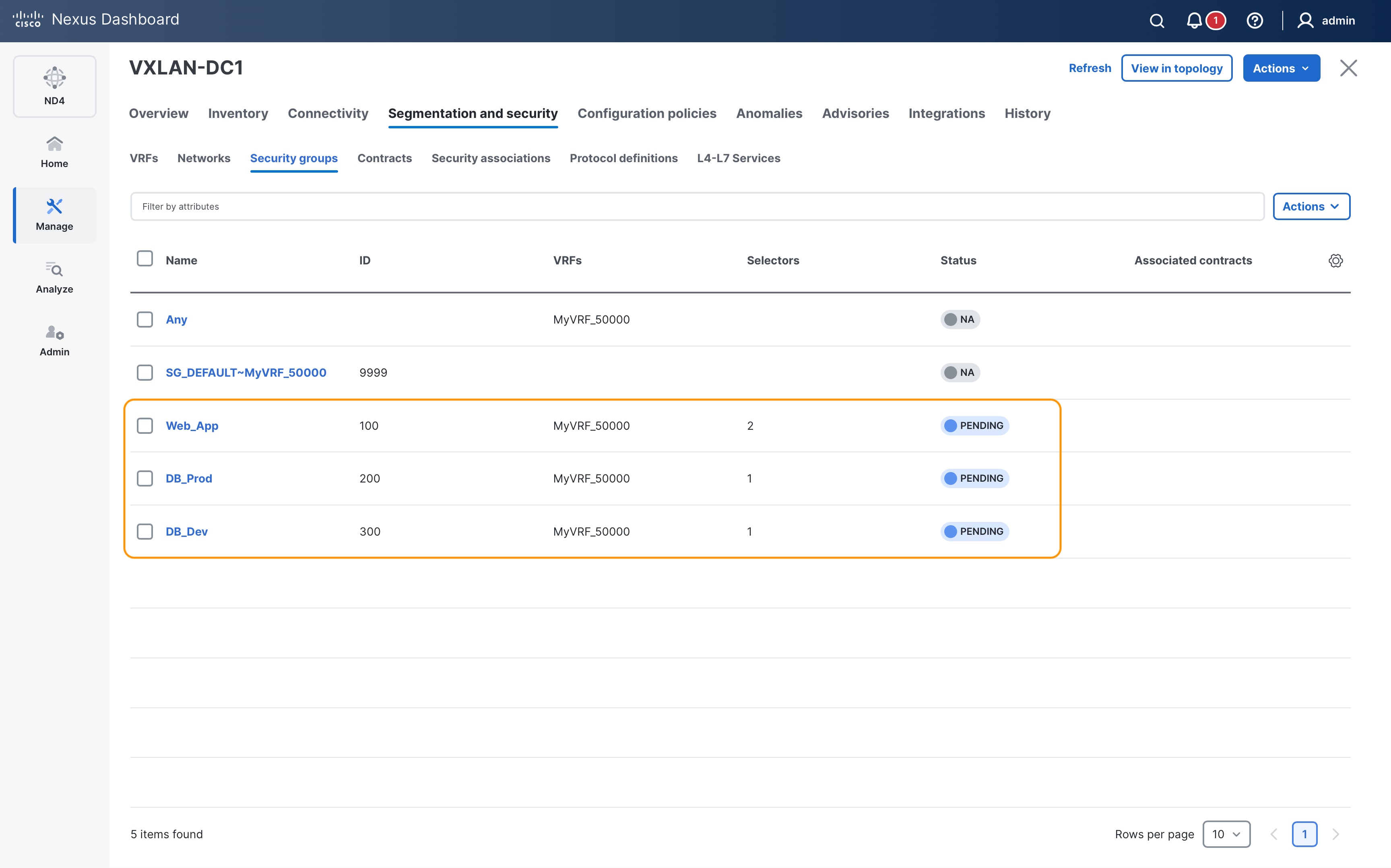
Select the SGs created and click on Deploy from Actions drop-down for Nexus Dashboard to push the required configuration to the switches:
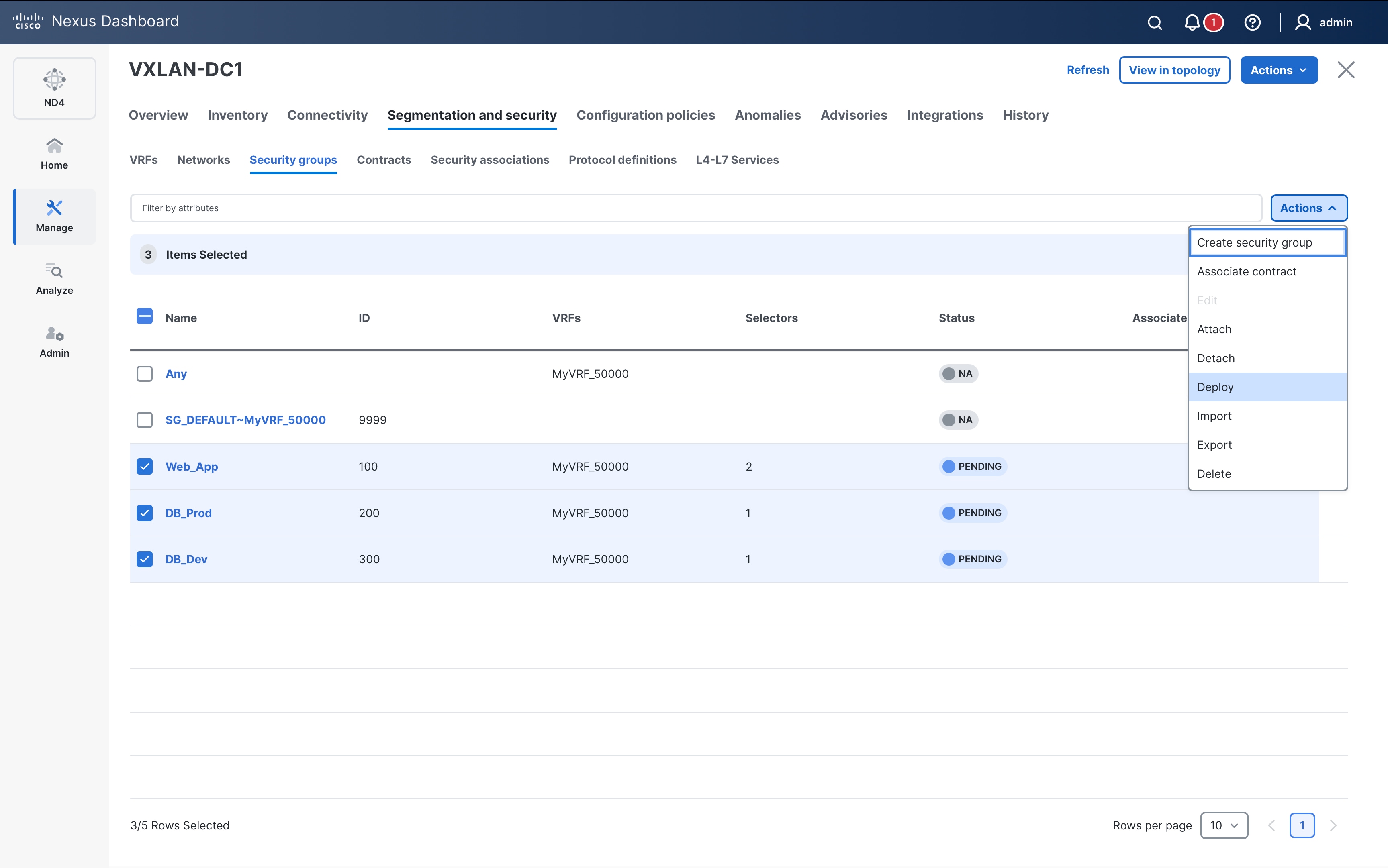
Choose Proceed to Full Switch Deploy (Recommended) option and click on Next button:
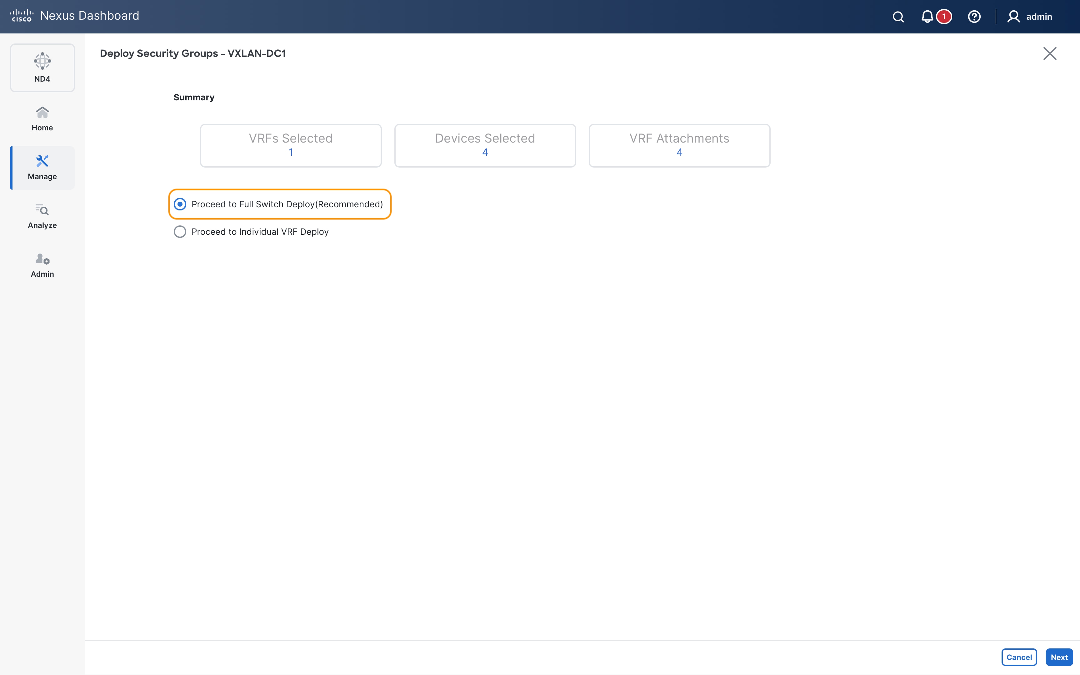
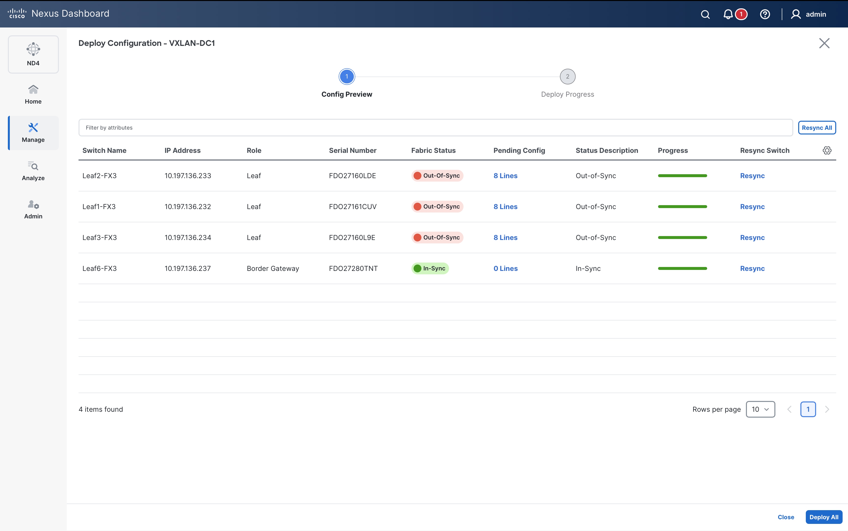
On Deploy Config page, click on Pending Config column review the config being pushed by ND:
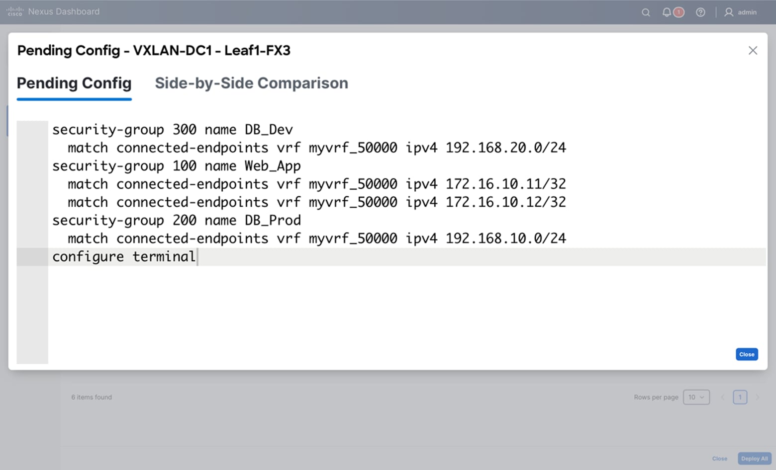
Step 8. Under Protocol Definitions tab, you can find the pre-defined traffic selectors:
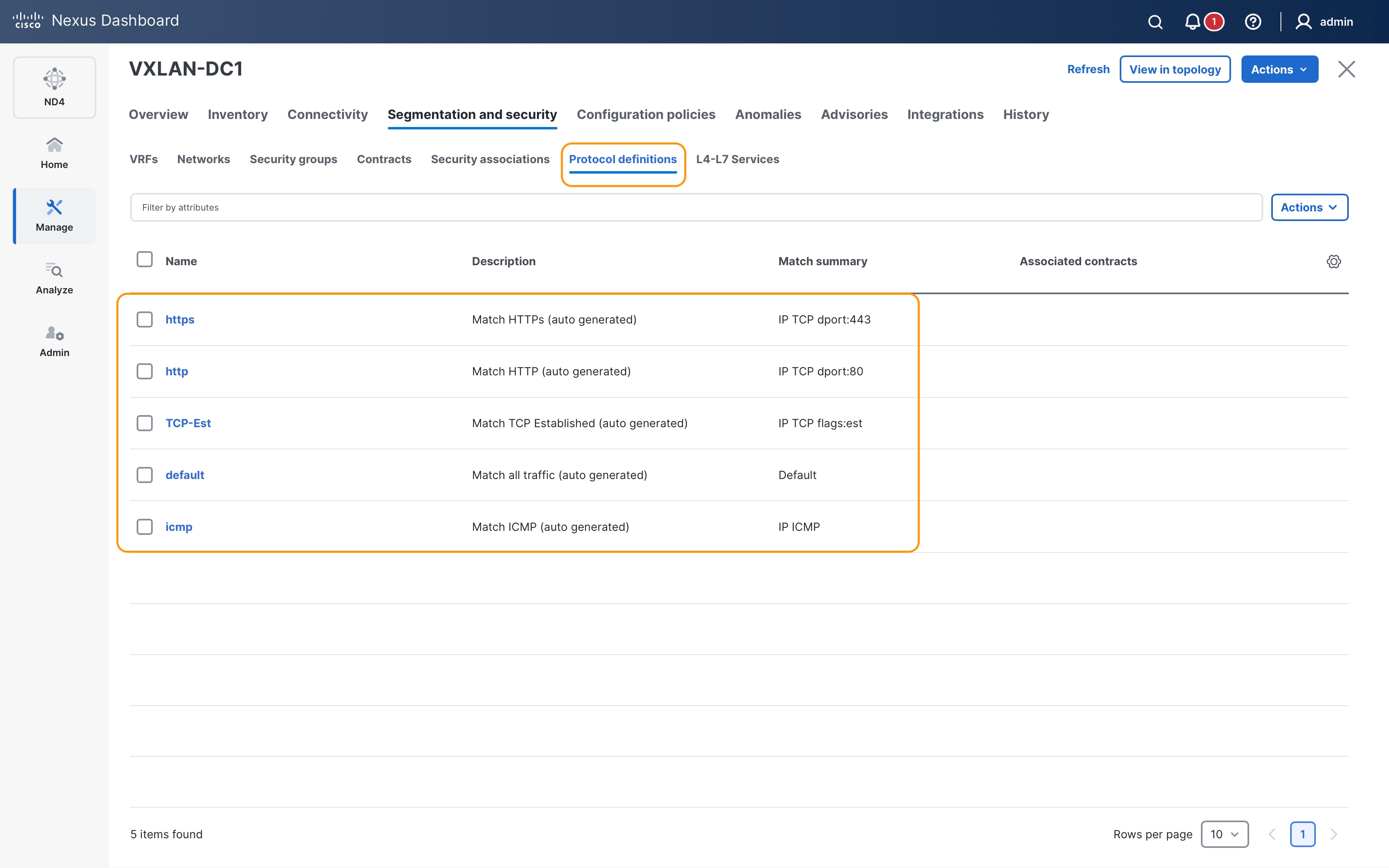
If needed, customized traffic selectors can be defined by clicking on Create security protocol definition from Actions drop-down on Protocol definitions tab:
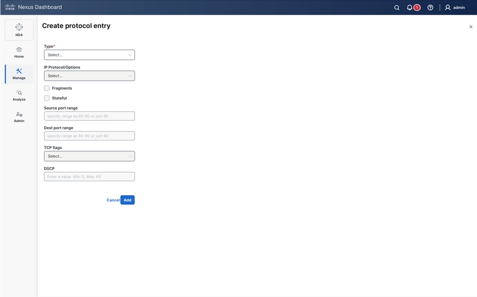
Step 9. Define the Contract by selecting Protocol Definition, Direction and Actions to be taken under Contract tab:
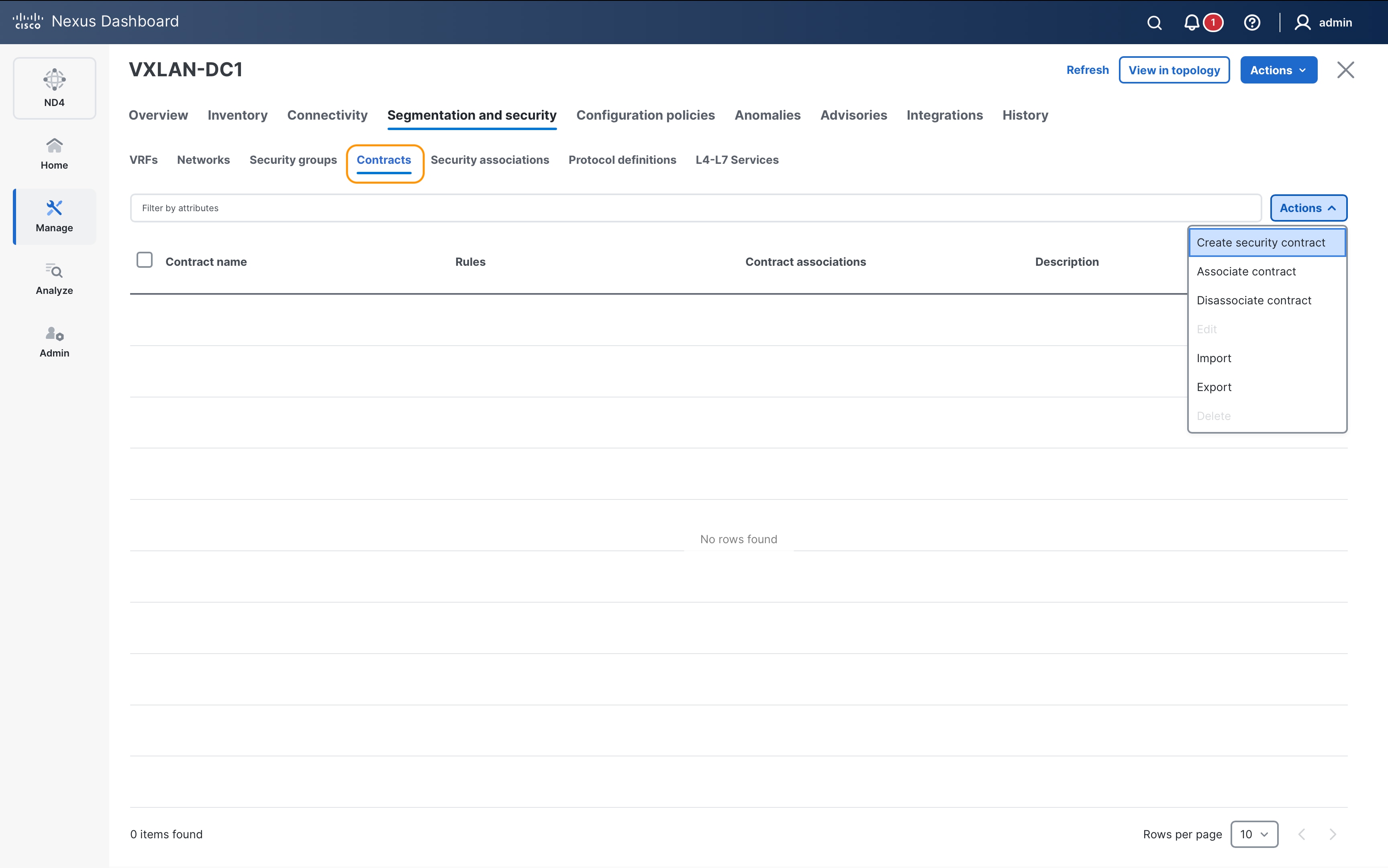
Protocol definition to permit HTTPs traffic:
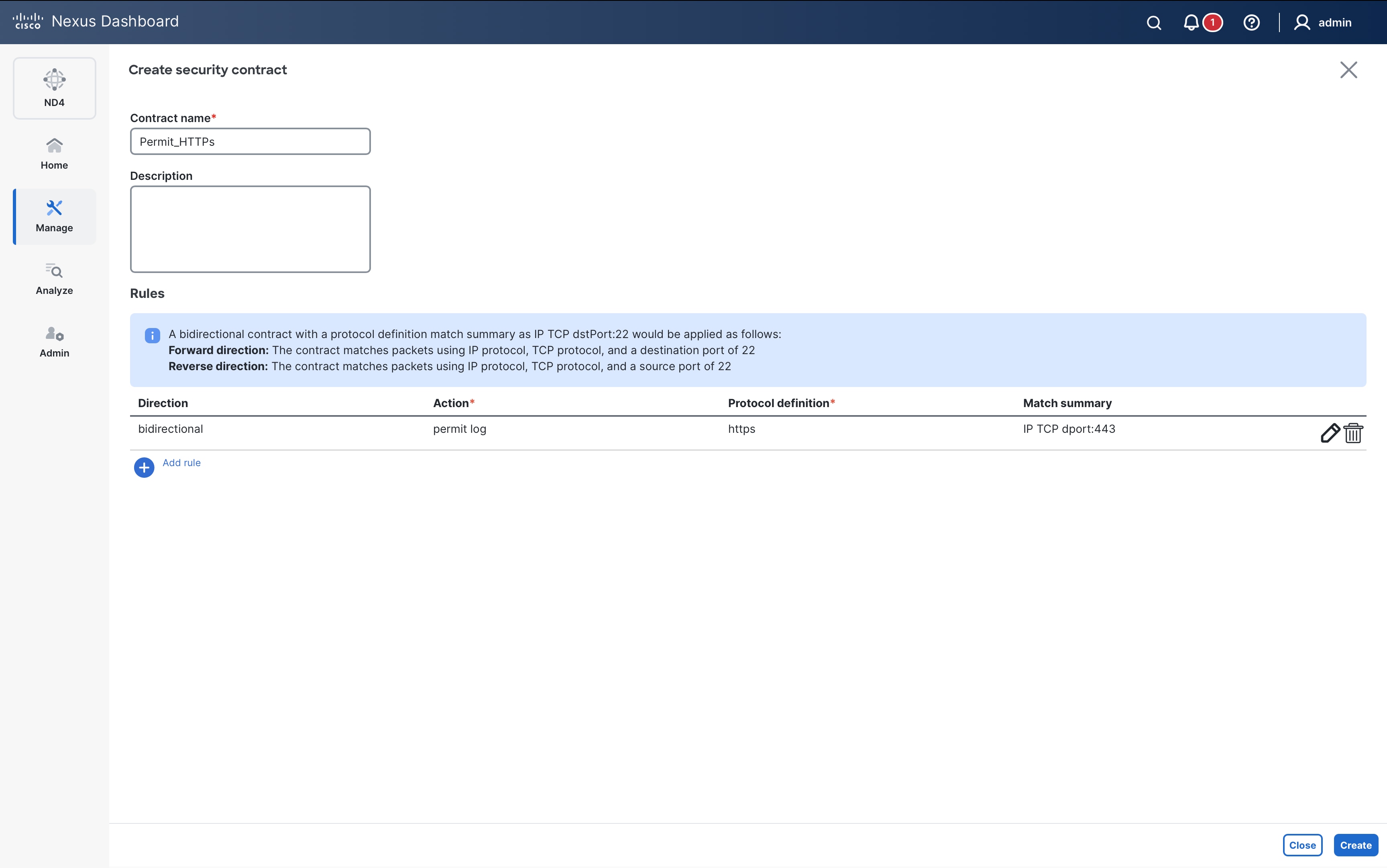
Protocol definition to permit HTTP traffic:

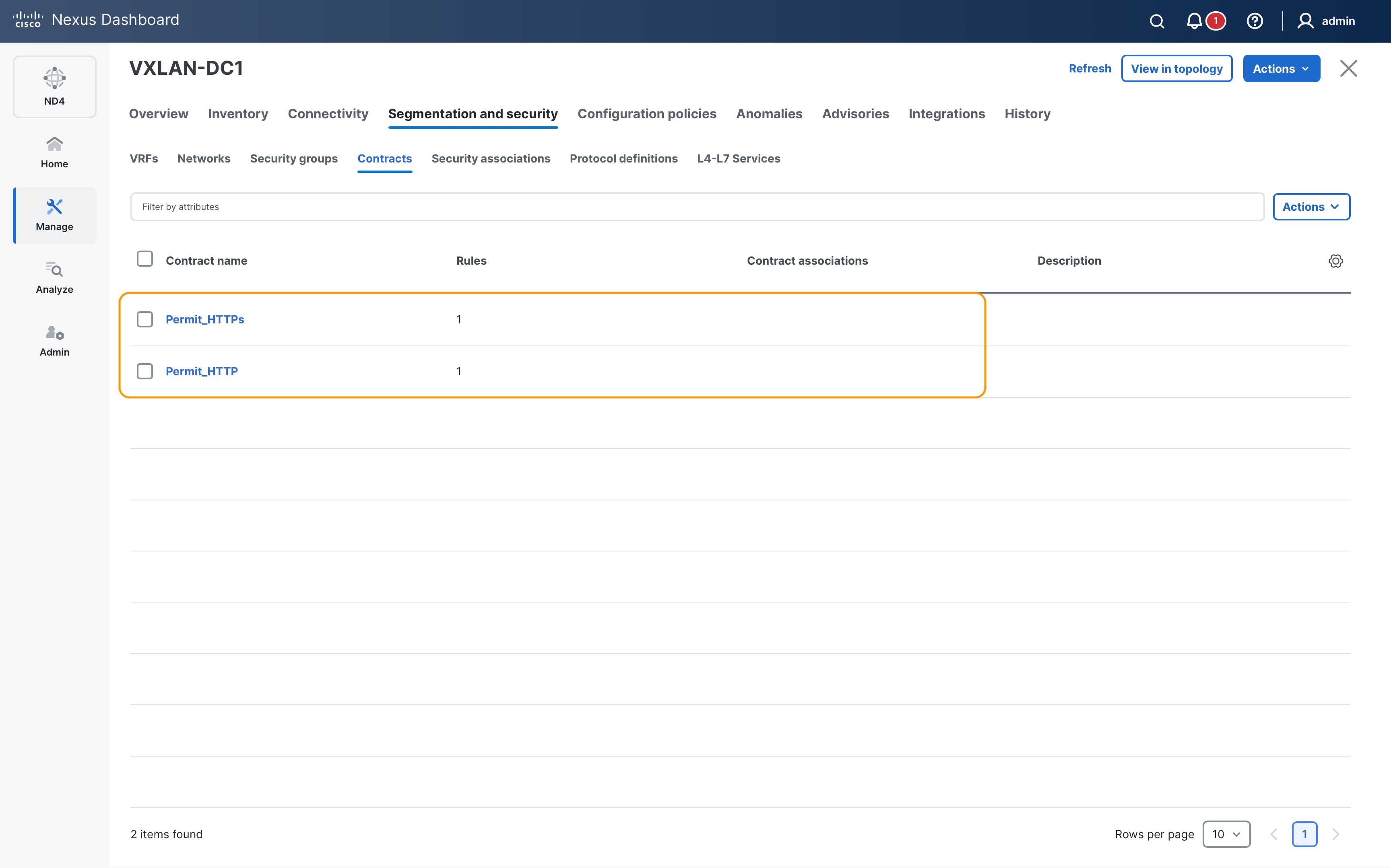
Step 10. The final step is to define the association between the SGs and the contract under the Security Associations tab:
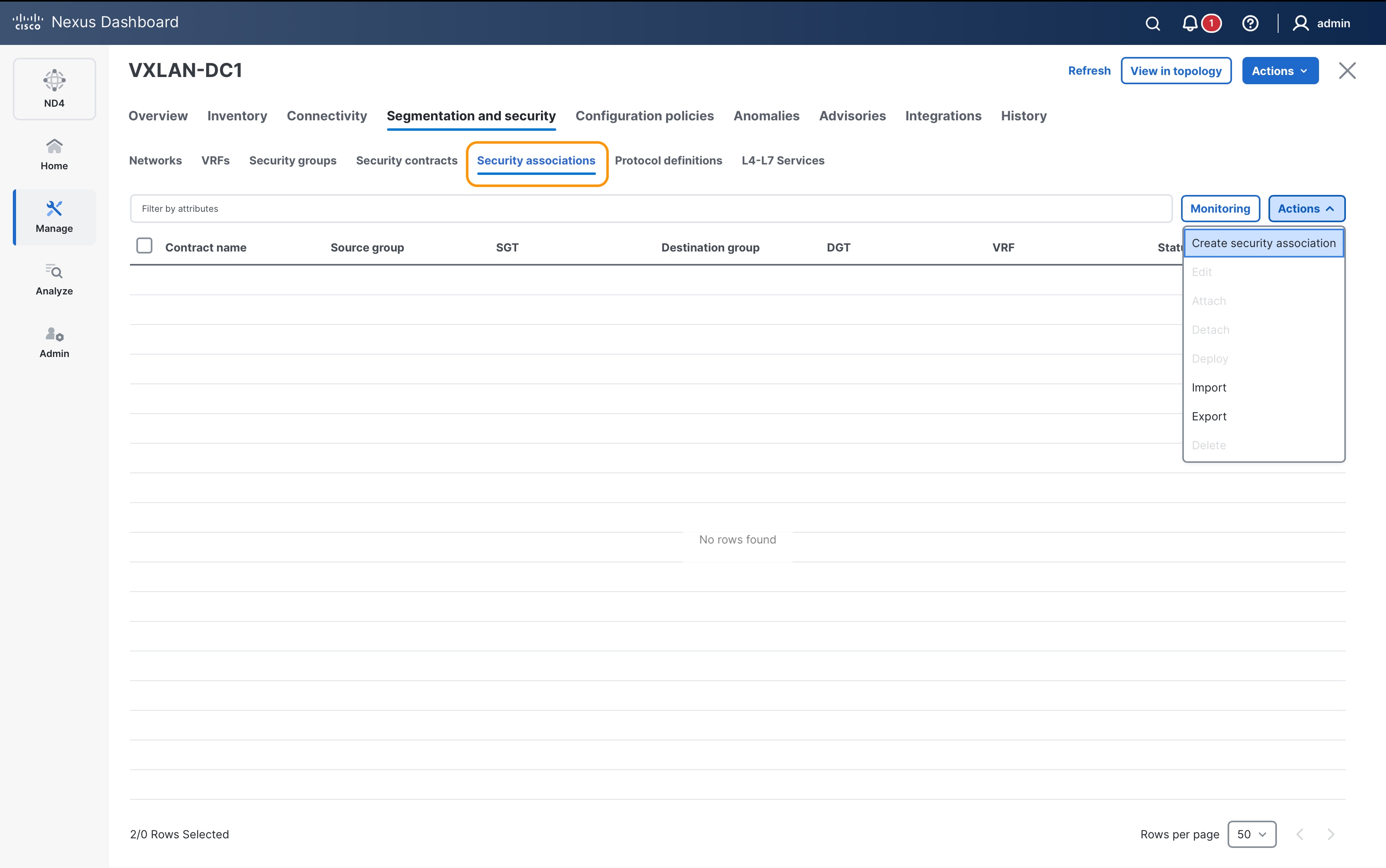
Define security association between source SG Web_App and destination SG DB_Prod using contract Permit_HTTPs.
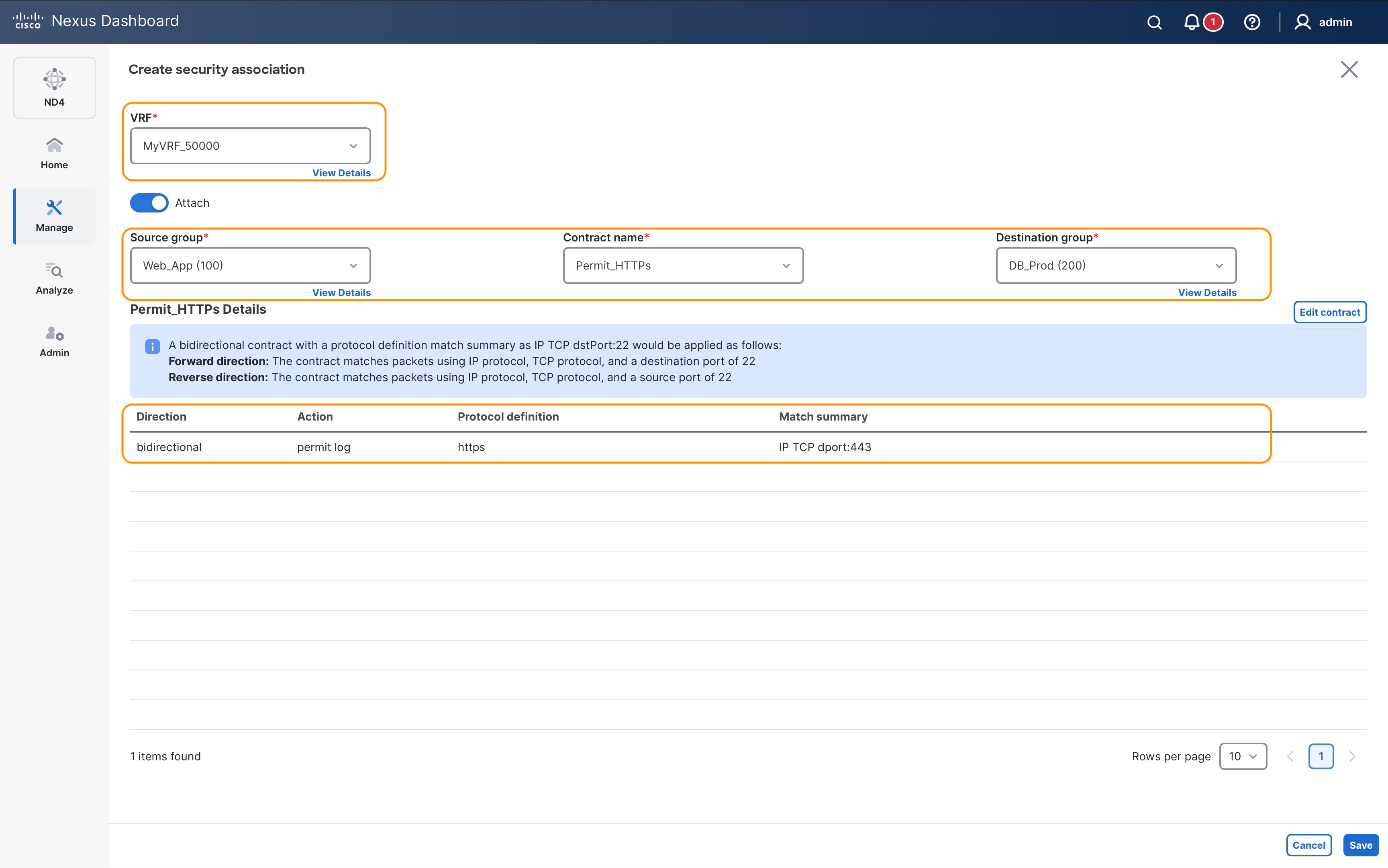
Similarly, define security association between source SG Web_App and destination SG DB_Prod using contract Permit_HTTP:
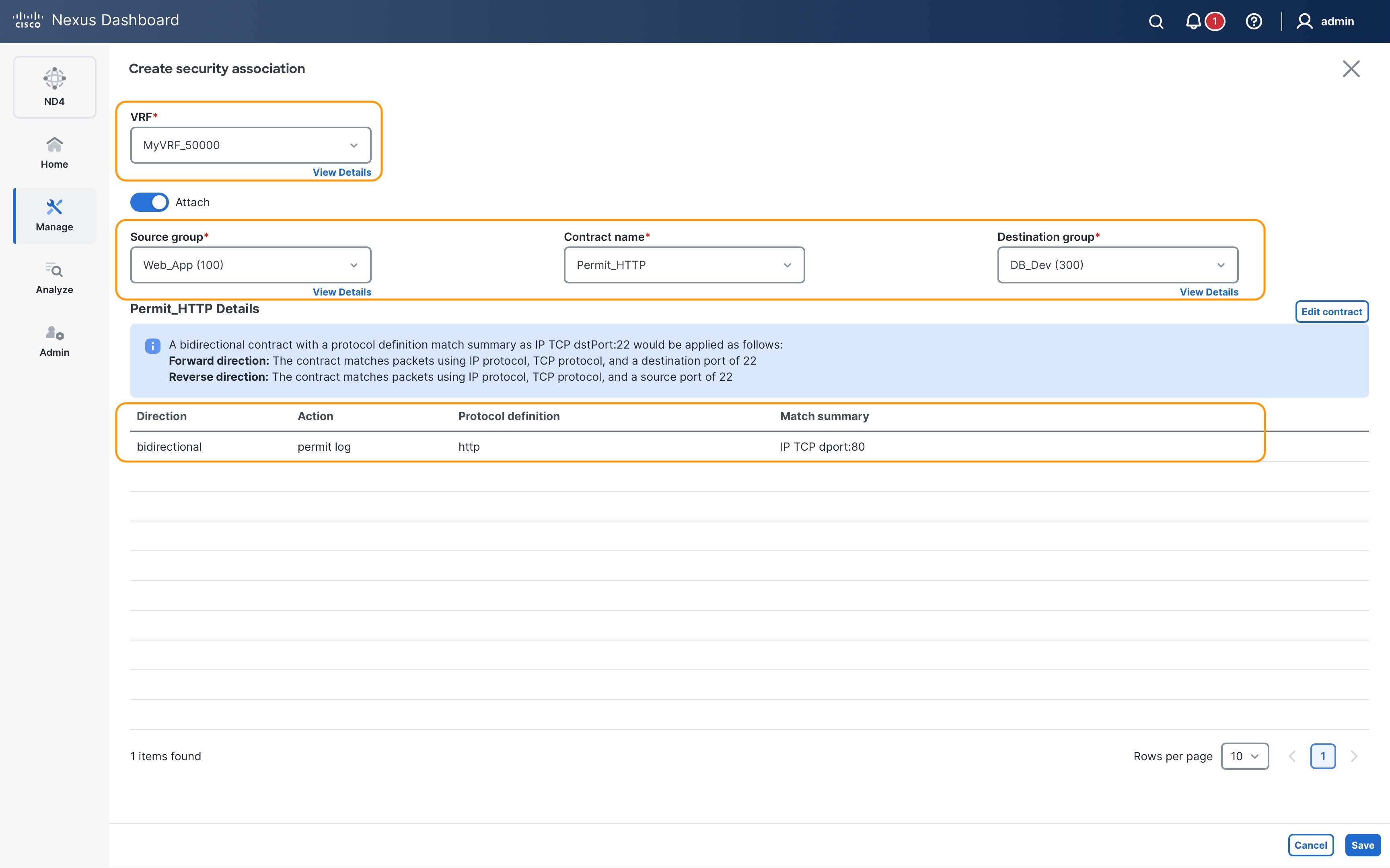
Once the associations are defined, you will notice Pending status for them.
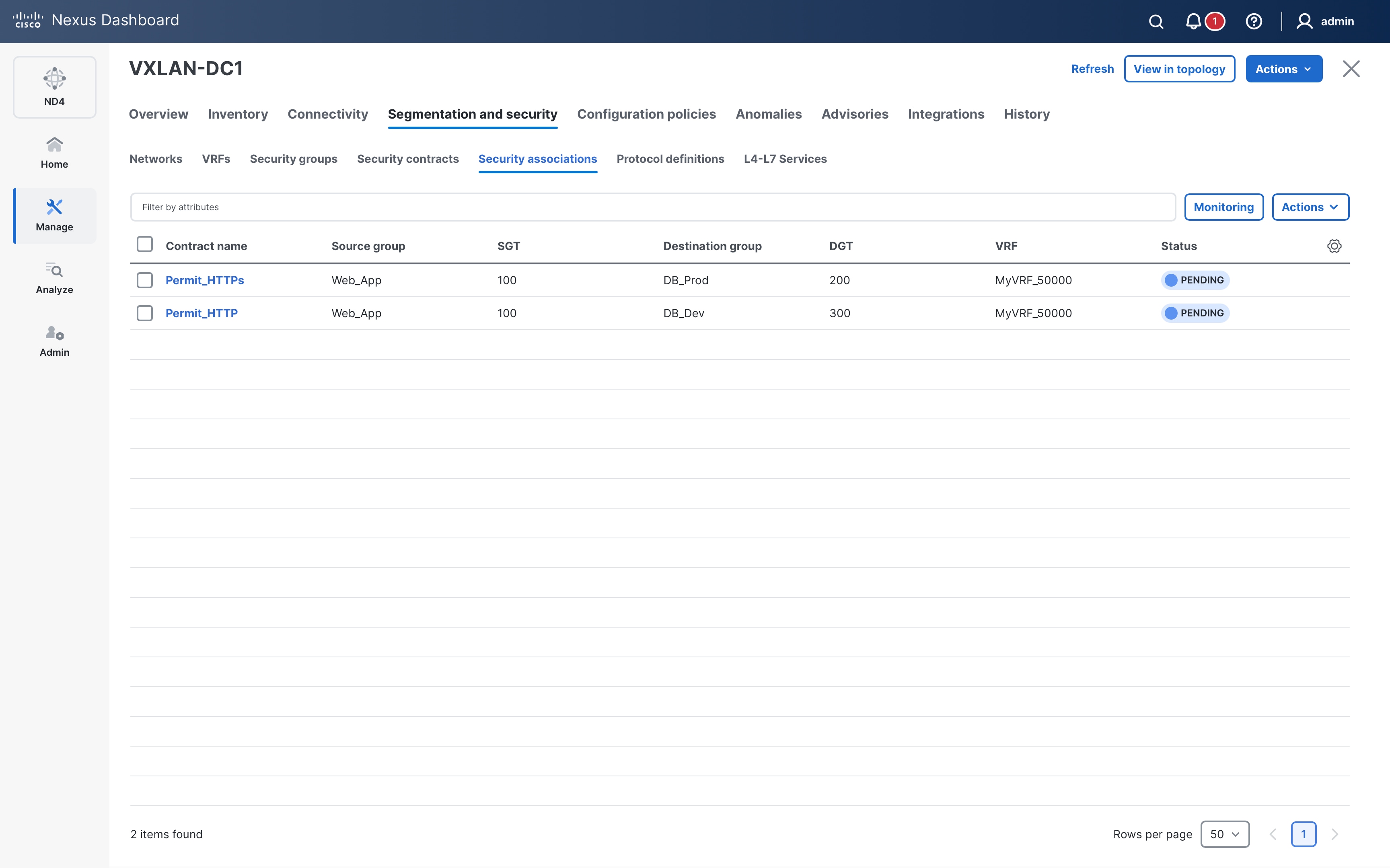
Select the associations and click on Deploy from Actions drop-down for ND to push configuration to the devices:
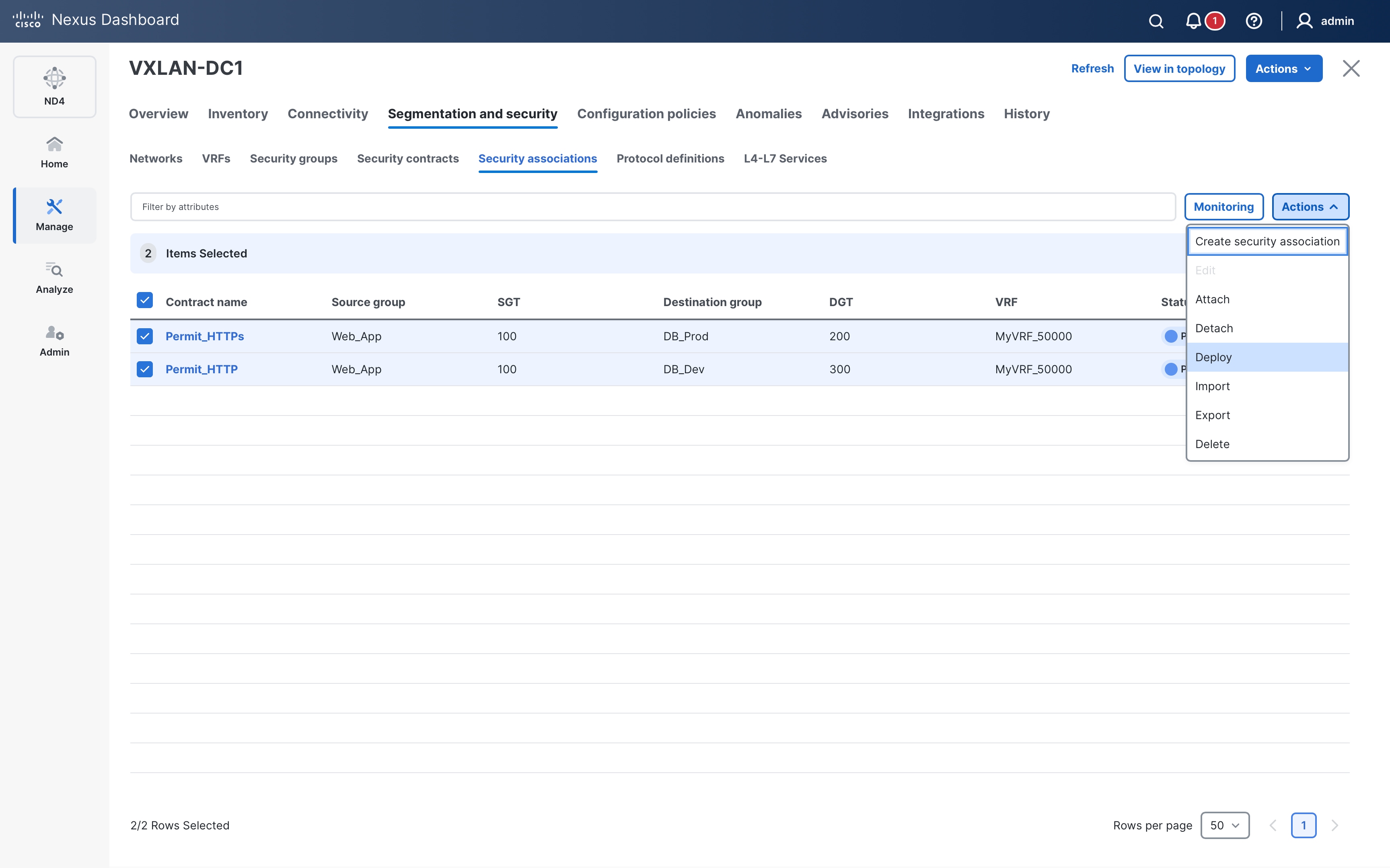
Optionally, review the configuration on the Deploy Config page.
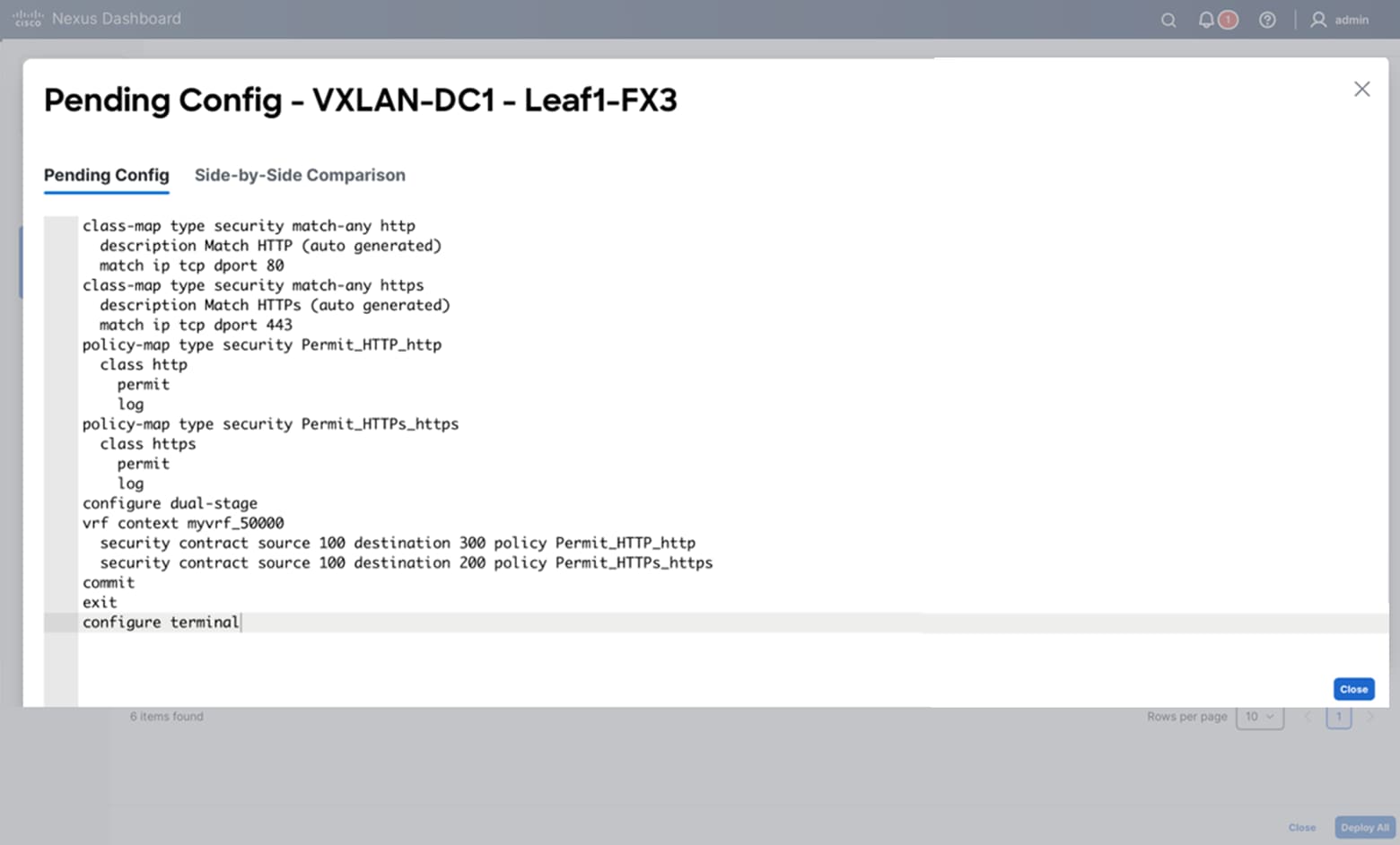
Monitoring of Security Contracts
ND also provides visibility into the enforced security policies by capturing the stats for the hits against each of the Security Associations. This information can be accessed by clicking on the Monitoring sub-tab found on the Security Association tab page:
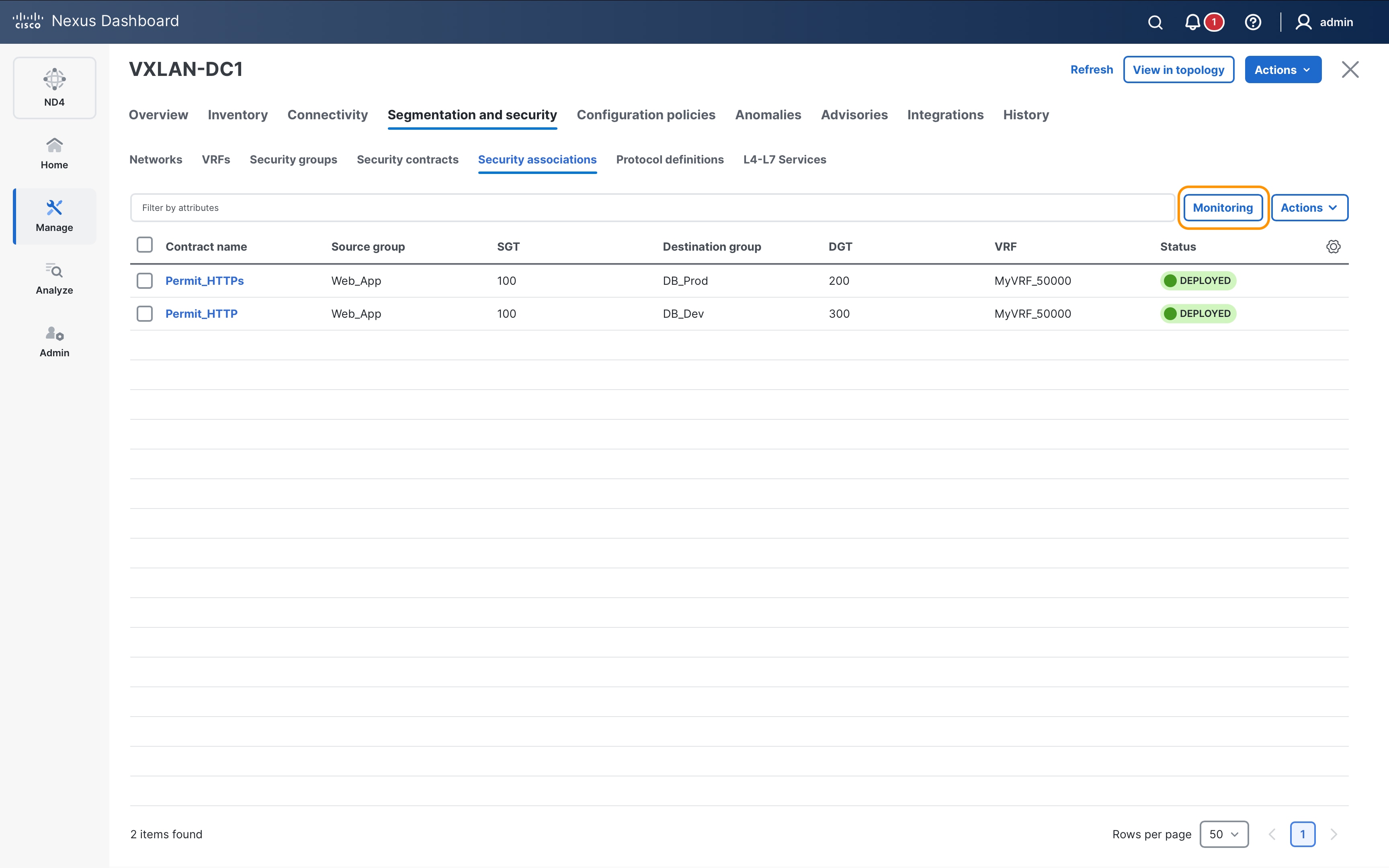
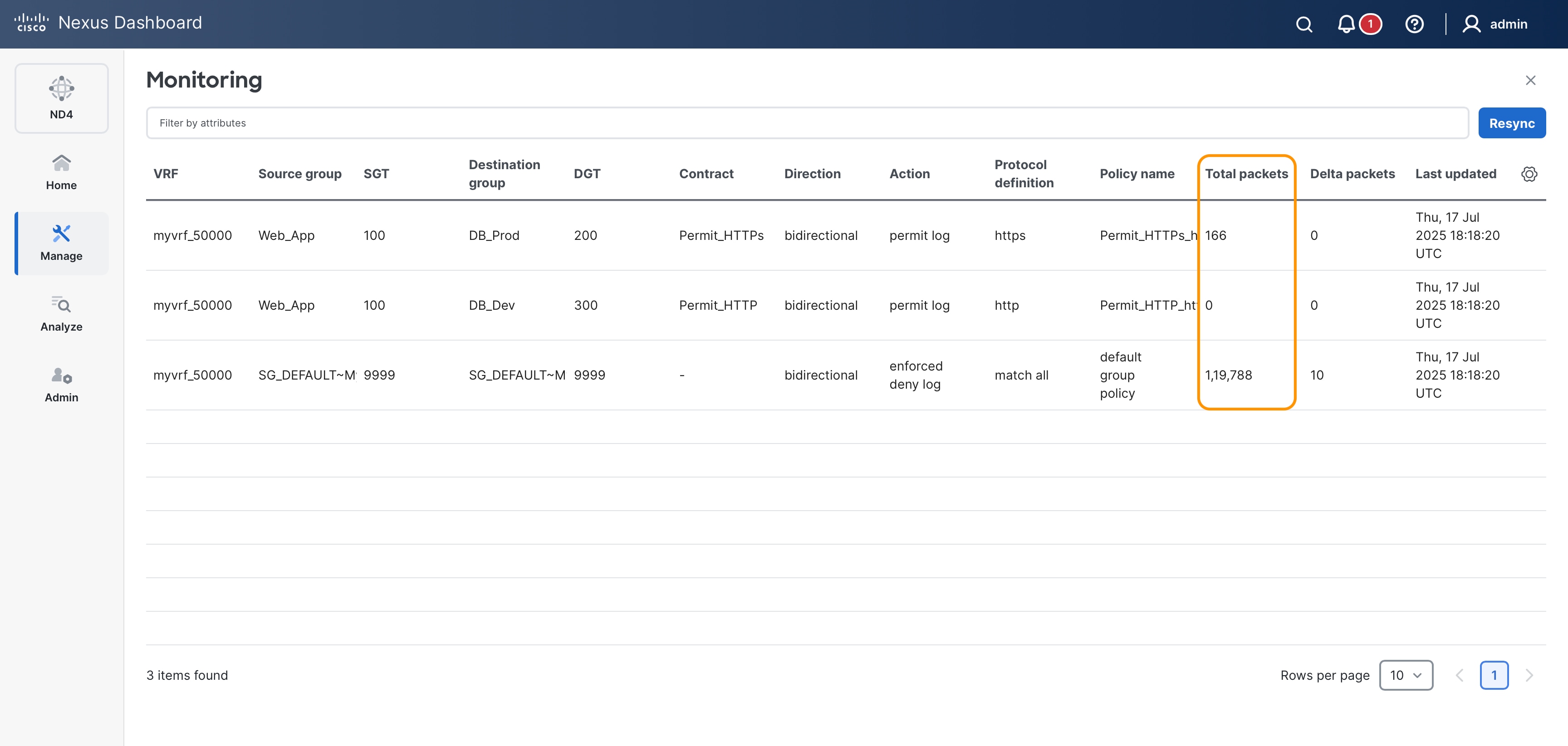
Securing resources within Data Centers is a critical priority in today's interconnected and increasingly threat-prone environments. Modern Data Centers, often designed as flat networks to support virtualization and scalability, present unique challenges in traffic control due to their lack of inherent segmentation. Traditional solutions such as Private VLANs (PVLANs) and Access Control Lists (ACLs) attempt to address these issues but face limitations in scalability, operational complexity, and adaptability to dynamic environments. Similarly, relying on firewalls for traffic control at scale can lead to high costs, bottlenecks, and performance degradation, ultimately restricting business agility.
Fabric-level network segmentation provides a transformative solution to these challenges by enabling the creation of smaller, isolated zones within the network. This approach allows for fine-grained traffic control directly within the fabric, avoiding the need for costly external solutions. It enhances security, optimizes performance, and ensures compliance while aligning with both technical and business objectives.
The VXLAN Group Policy Option (GPO) further advances this concept by integrating segmentation and policy enforcement directly into the fabric. This eliminates the need for external devices like firewalls, as traffic remains within the fabric, ensuring no loss of bandwidth or performance. By leveraging the existing VXLAN header to carry Security Group Tags (SGTs), VXLAN GPO enables line-rate policy enforcement without adding complexity or overhead.
The key business benefits of VXLAN GPO include:
● Cost Efficiency: Eliminates the need for standalone firewalls, reducing both capital and operational expenses while ensuring robust security.
● Operational Simplicity: Policies are enforced natively within the fabric, minimizing complexity and reducing manual intervention.
● Scalability and Flexibility: Easily adapts to dynamic environments, supporting the agility required for modern workloads and hybrid cloud deployments.
● Enhanced Security and Performance: Provides line-rate policy enforcement, ensuring security without compromising high-speed, uninterrupted operations.
● Cisco Nexus 9000 Series NX-OS Micro-segmentation for VXLAN Fabrics Using Group Policy Option (GPO)
Cisco and the Cisco logo are trademarks or registered trademarks of Cisco and/or its affiliates in the U.S. and other countries. To view a list of Cisco trademarks, go to this URL: https://www.cisco.com/c/en/us/about/legal/trademarks.html. Third-party trademarks mentioned are the property of their respective owners. The use of the word partner does not imply a partnership relationship between Cisco and any other company. (1721R)
Any Internet Protocol (IP) addresses and phone numbers used in this document are not intended to be actual addresses and phone numbers. Any examples, command display output, network topology diagrams, and other figures in the document are shown for illustrative purposes only. Any use of actual IP addresses or phone numbers in illustrative content is unintentional and coincidental.
© 2025 Cisco Systems, Inc. All rights reserved.