Deploying and Verifying Cisco Nexus One Fabric Connectivity and Policy between ACI Fabrics
Available Languages
Bias-Free Language
The documentation set for this product strives to use bias-free language. For the purposes of this documentation set, bias-free is defined as language that does not imply discrimination based on age, disability, gender, racial identity, ethnic identity, sexual orientation, socioeconomic status, and intersectionality. Exceptions may be present in the documentation due to language that is hardcoded in the user interfaces of the product software, language used based on RFP documentation, or language that is used by a referenced third-party product. Learn more about how Cisco is using Inclusive Language.
- US/Canada 800-553-2447
- Worldwide Support Phone Numbers
- All Tools
 Feedback
 Feedback
| Date |
Change |
Location |
| 2026-09-2 |
Initial publication |
This document |
Goals of this Document
The goals of this document are to elaborate on the requirements and deployment procedures for infrastructure connectivity and logical tenant communication between two ACI sites using Border Gateways. It specifically focuses on APIC configuration without relying on external tools such as Nexus Dashboard. The guide covers Layer 2, Layer 3, shared services, and end-to-end policy extension, ensuring consistent policy enforcement across interconnected ACI sites.
This guide details infrastructure VXLAN connectivity using either direct BGP EVPN peering (non-Route Server) or a Border Gateway Route Server. While both are covered, the design focus remains on the non-Route Server model. The “User Tenant Baseline Configuration” section is essential for understanding the subsequent use cases; readers should review this foundational content and the following scenarios in the order presented.
Note: Throughout this document, the terms “site” and “fabric” are used interchangeably.
This document uses the following terms, with which you will need to be familiar:
● BD: bridge domain
● EPG: endpoint group
● ESG: endpoint security group
● EP: endpoint residing in an ACI fabric
● L3Out: Layer 3 Out or external routed network
● L3Out EPG also known as External EPG: subnet-based EPG in L3Out
● VRF: Virtual Routing and Forwarding
● Border leaf: ACI leaf where L3Out is deployed
● Border gateway: ACI leaf that is used to connect to other VXLAN EVPN domain
● ISN: The Inter‑Site Network that provides connectivity between Border Gateways deployed in separate ACI sites
● pcTag: Policy Class Tag is a numeric ID used for internal representation of EPG/ESG also referred to as Source Class (sclass) or Destination Class (dclass)
● CLI: Command-Line Interface
● DF: Designated Forwarder, a role assigned to a specific Border Gateway that is responsible for forwarding BUM (Broadcast, Unknown Unicast, and Multicast) traffic within a given Bridge Domain (BD)
● PIP: Primary IP Address, a unique loopback IP address assigned to each individual Border Gateway, it is used as source for VXLAN tunnel
Reader Prerequisite Knowledge
● Familiarity with Cisco ACI core concepts such as Tenants, BDs, EPGs, and ESGs.
● Understanding of VXLAN and BGP EVPN technologies.
● For more information, see the Cisco ACI white papers listing.
Deployment Requirements
● ACI Release: 6.1(5) or higher is required to support multiple independent ACI sites communicating through border gateways and to leverage enhanced features such as Layer 2, Layer 3 connectivity and policy extension between sites.
● Logical Model: ESGs are required, and BDs must be configured in Flooding mode for Unknown Unicast traffic. ESGs are the required security model for flexible and scalable endpoint classification in Multi-Site deployments.
● Border Gateway hardware: Cisco Nexus 9000 Series switches of the FX generation or later, with a minimum of 32 GB of RAM, are required to support Border Gateway functionality. At the time of writing, a Border Gateway in Cisco ACI is a dedicated leaf node that cannot host a tenant L3Out or an endpoint in an EPG/ESG.
● Inter-Site Network: The Inter-Site Network must support external BGP (eBGP) for underlay connectivity.
As of ACI Release 6.1(5), interconnecting multiple ACI Sites via Border Gateways became a supported capability. Broadly, there are three primary methods for connecting ACI sites:
● Independent Sites: In this model, each ACI site operates autonomously. Local APIC administrators are responsible for configuring tenants, VRFs, BDs and Contracts independently on each site. One ACI site perceives the other as an external Layer 2 or Layer 3 network, with no inherent policy synchronization. Networking services rely solely on EPG static path binding and L3Out. This architecture presents several limitations, including complex contract management, lack of support for an “app-centric mode” (where multiple EPGs share a single stretched BD), and the absence of a pervasive gateway across sites.
● Nexus Dashboard Orchestrator (NDO): Now known as Orchestration Service in Nexus Dashboard (ND) starting from ND release 4.1(1), NDO provides a single pane of glass for configuring inter-site connectivity and applying consistent network and policy across ACI sites. Site-to-site VXLAN connectivity is established between ACI spines.
● Border Gateway Interconnect: This newer design option centralizes the interconnectivity between ACI sites through dedicated Border Gateways. It facilitates Layer 2 and Layer 3 networking services and policy using standard VXLAN encapsulation for the data plane and BGP EVPN for the control plane. The VXLAN connectivity between sites is key to maintaining a pervasive gateway across ACI sites. Centralized provisioning can be achieved through programmatic interfaces, including the APIC REST API, as well as automation frameworks such as Ansible and Terraform. As a roadmap, Nexus Dashboard will evolve into a central orchestrator for both infrastructure connectivity and logical tenant extension between sites.
This document further elaborates on the requirements and deployment procedures for infrastructure connectivity and logical tenant communication, encompassing Layer 2, Layer 3, and shared services between two ACI sites using Border Gateway.
In this document, the terms “site” and “fabric” are used interchangeably. Both refer to the same ACI domain managed by a single APIC cluster. This ACI domain can be either a single-pod ACI site or a multi-pod ACI site.
The topology below is intended for configuration and deployment demonstrations only. For production environments requiring high availability and specific business requirements, this topology can be scaled by adding more leaf, border gateway and spine switches.
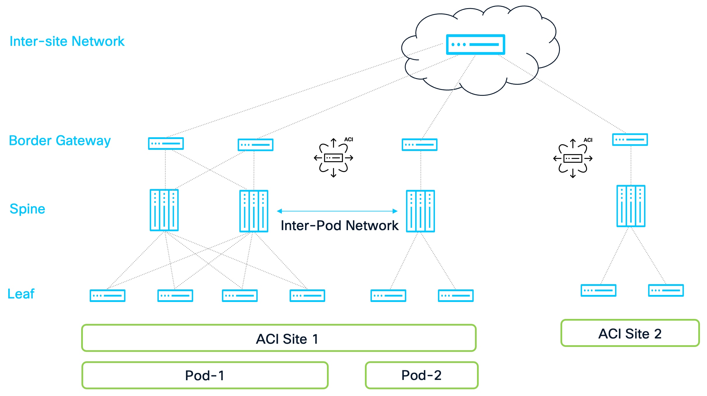
Figure 1. Reference physical topology
The figure below illustrates the IP addressing and BGP AS numbers used in the guide. Although the examples in this guide use /30 subnets for point-to-point links, /31 subnets are also valid options.
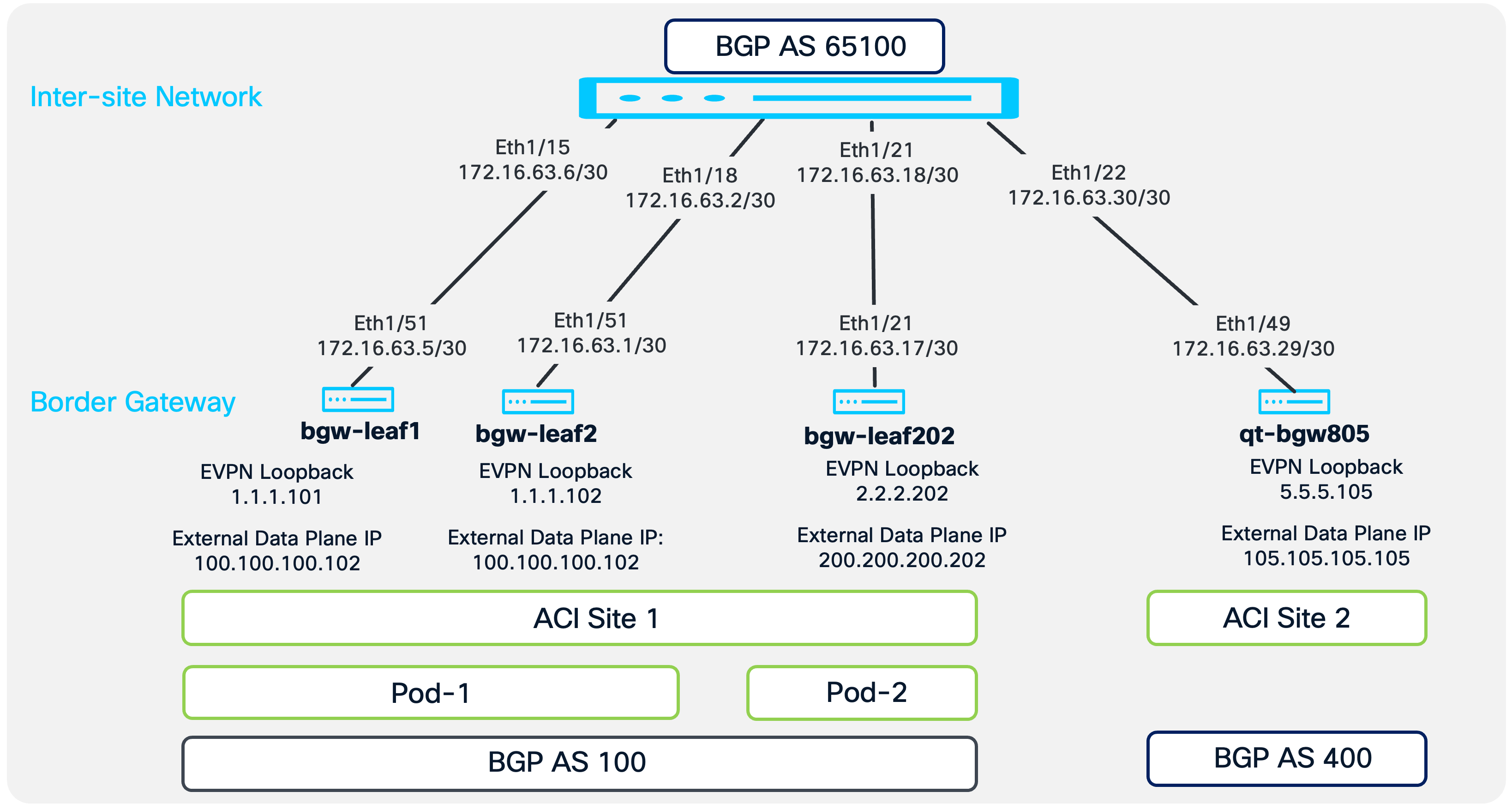
Figure 2. IP Addressing and BGP AS numbers
● The External Data Plane IP, also known as the Multi-Site External VIP, is a virtual IP shared across all Border Gateways within the same ACI Pod. This loopback IP is user-configured per Pod and serves as the next-hop for Type-2 and Type-5 EVPN routes advertised to remote ACI site (VXLAN EVPN fabric). It is set up when creating Border Gateway Sets on the APIC controller.
● EVPN Loopback, also referred to as BGW PIP or VXLAN-RTEP, is a unique loopback IP address assigned to each Border Gateway. It serves as the source IP for all traffic destined to the remote VXLAN EVPN domain and functions as the next-hop for Type-5 prefixes received from the remote ACI site (VXLAN EVPN domain), which are injected into the local ACI fabric via VPNv4/VPNv6. This loopback address is configured during the setup of the VXLAN Infra L3Out.
This section introduces several supported use cases between ACI sites utilizing Border Gateways:
● Intra-subnet Communication (Bridged Flow): Stretched Layer 2 Network: Communication between endpoints residing in the same subnet across different ACI sites.
● Inter-subnet Communication (Routed Flow): Layer 3 communication between:
● Directly connected endpoints across ACI Sites (e.g., an endpoint in Site 1 communicating with an endpoint in Site 2).
● External endpoints across ACI Sites (e.g., an external endpoint through Site 1 communicating with an external endpoint through Site 2).
● North-South Communication across sites: Communication from internal endpoint in one site to external endpoint in another Site through L3Out in the same VRF.
● Shared Service (Inter-VRF): Communication between endpoints located in different VRFs across different ACI sites.
● Shared L3Out: Communication between endpoints located in one VRF in one ACI Site to external endpoint in a different VRF in another ACI Site.
For details, please refer to this section Overlay Networking and Use Cases Deployment Details.
This section provides an overview of the control plane established between two ACI sites. ACI Border Gateways (BGWs) build full-mesh BGP EVPN sessions with each other to facilitate this inter-site communication. Starting from ACI release 6.1(6) and 6.2(2), Route-Server deployments are also supported as an alternative topology, providing greater scalability and simplified BGP peering management.
Several types of EVPN sessions are established between ACI Border Gateways:
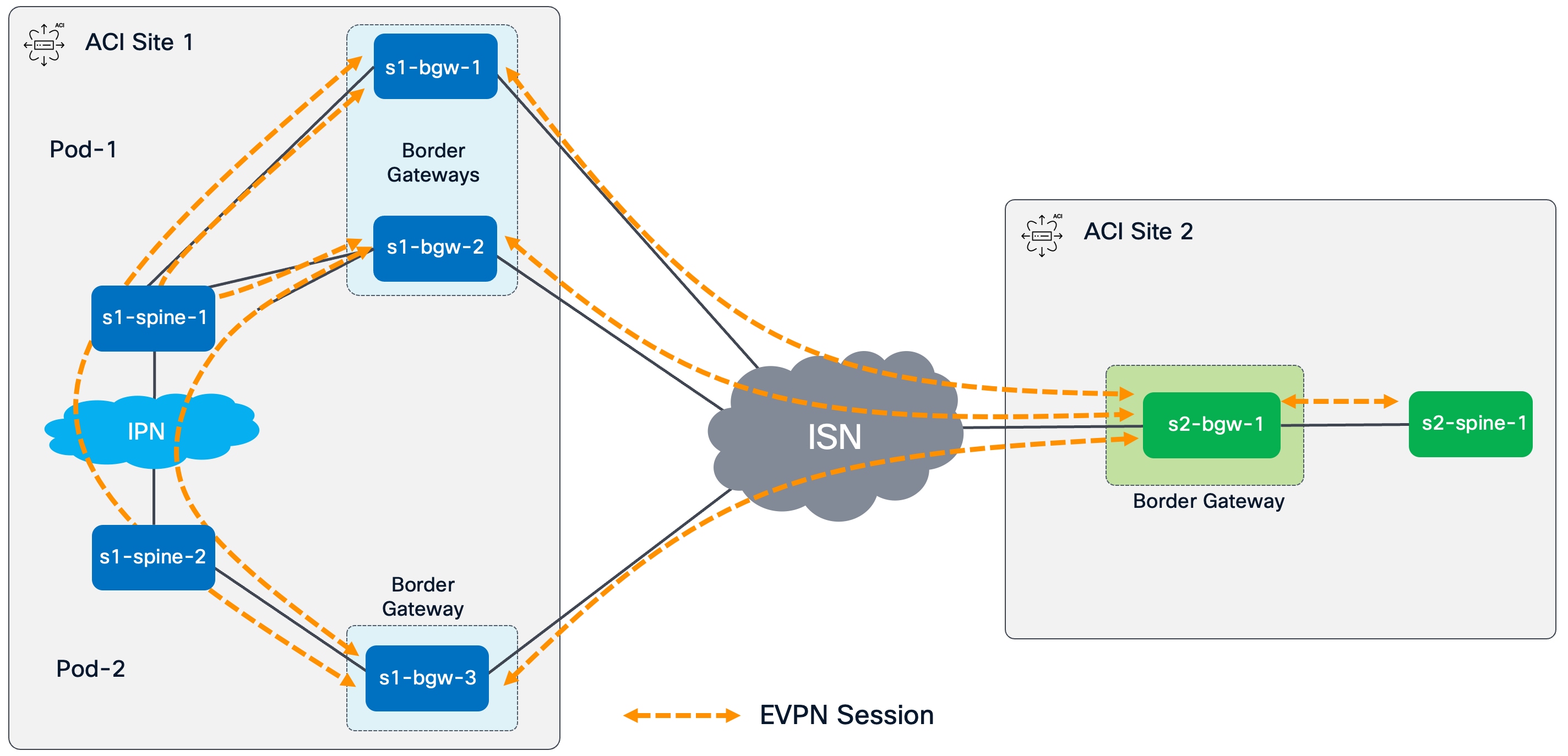
Figure 3. Border Gateways EVPN Sessions
● EVPN sessions between Border Gateways within the same Pod.
● EVPN sessions between Border Gateways and spine switches within the same Pod.
● EVPN sessions between Border Gateways across different Pods, which are part of the same ACI Site.
● EVPN sessions between Border Gateways across different ACI sites.
● The primary purpose of these EVPN sessions is to advertise EVPN routes both within and across sites. Although these routes include Type-2, Type-3, Type-4, and Type-5 routes, this document will focus on Type-2 and Type-5 routes.
● Type-2 routes are used to advertise endpoint information, including MAC and MAC-IP addresses.
● Type-5 routes, conversely, advertise subnet reachability across ACI sites both for BD subnets and external prefixes reachable via L3Outs.
● Type-3 routes, also known as Inclusive Multicast Ethernet Tag (IMET) routes, are exchanged between ACI Border Gateways (BGWs) to build the Bridge Domain (BD) flood list toward the remote ACI Site.
● Type-4 Ethernet Segment routes are used for Designated Forwarder (DF) election among all ACI BGWs across all Pods within the same ACI Site for each deployed Bridge Domain. The DF election ensures that only one BGW is responsible for sending and receiving BUM (Broadcast, Unknown Unicast, and Multicast) traffic to and from the remote ACI Sites, preventing duplicate traffic forwarding.
As ACI is a policy-aware site, the EVPN route type is extended to carry the pcTag (policy-control Tag), also known as Class ID information, across ACI sites. Based on the pcTag information learned from the BGP EVPN control plane, ACI Border Gateways apply policies to allow or deny communication across sites. For VRFs stretched via Border Gateways, the use of Endpoint Security Groups (ESGs) is mandatory, as ESGs provide the policy classification required for consistent enforcement across sites. Policy implementation is, as usual, achieved using the contract model. Communication between endpoints within the same ESG is permitted without a contract, while communication between endpoints in different ESGs requires a contract with a permit filter.
EVPN establishes overlay sessions between the loopback interfaces (PIPs) of the Border Gateways. The reachability between these loopback interfaces is handled by the underlay protocol, which in this case is BGP. ACI Border Gateways are configured with external BGP (eBGP) peering to the Inter-Site Network (ISN) to ensure loopback address reachability between Border Gateways across Pods and sites. The configuration of the ISN devices can be automated by Nexus Dashboard or by API, or it can be performed manually using the CLI. The configuration on the ACI Border Gateway itself is managed via the APIC in each site. Centralized configuration for both ACI sites will be supported through Nexus Dashboard beginning with Release 4.4(1).
APIC automates the allocation of VXLAN VNIs for both VRF and BD VNIs. Consequently, it is common to see different VNI values for the same network constructs across different ACI sites. As shown in the screenshot below, site 1 uses VRF VNI 2162688, while site 2 uses VRF VNI 2097152. This same discrepancy occurs with BD VNIs. Without VNI normalization or translation, routes cannot be successfully exchanged between these sites and consequently the network constructs (VRFs or BDs) cannot be functionally extended.
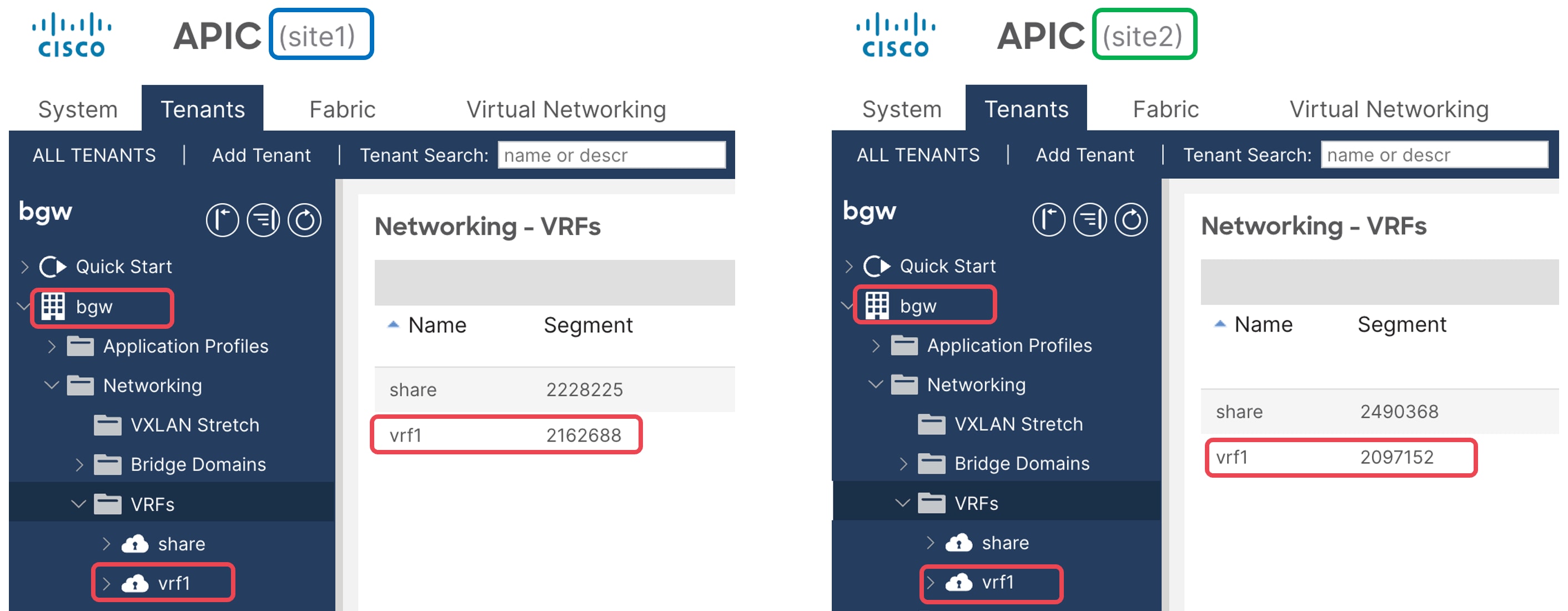
Figure 4. Local VRF VNI on each ACI Site
To support route exchange between ACI sites with differing local VNIs, Cisco ACI utilizes a normalized VNI (also known as a global VNI). Essentially, the Border Gateway (BGW) facilitates all inter-site route exchanges through this normalized VNI. At a high level, when a BGW receives a local route from its home site, it performs a VNI translation from the local VNI to the normalized VNI before advertising the route. Conversely, the BGW at the destination site receives these updates and translates the normalized VNI back to its own local VNI before propagating the update to the spines within its home site.
While the normalized VNI is defined individually on each ACI site, the assigned values must be identical across all sites when stretching a VRF or BD to another site. The normalized VNI is defined when associating them with the site’s Border Gateway Set. Similarly, when deploying the same ESG across sites, the normalized pcTag must also be identical across all sites. This ESG is used to classify local resources (such as endpoints and prefixes from local L3Out) and/or remote resources to consistently apply the policy. These concepts and their associated workflows are introduced in the subsequent sections of this document. The figure below illustrates the local VRF (Layer 3) VNIs and their corresponding Normalized VNIs. The same applies to local Bridge Domain (Layer 2) VNIs and their corresponding Normalized BD VNIs.
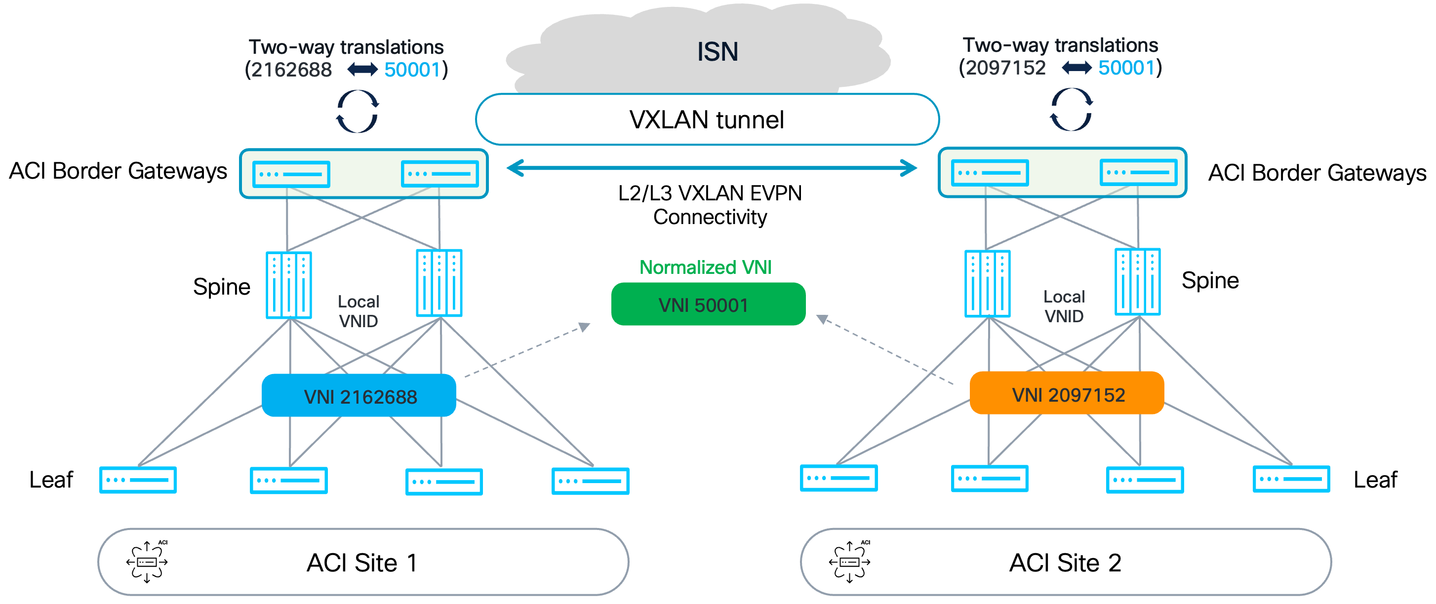
Figure 5. Normalized VNI two-way translations
Intra-site traffic behavior remains unchanged and continues to use iVXLAN encapsulation, which is the standard ACI data plane behavior. For inter-site traffic, however, the ACI Border Gateways (BGWs) on each site encapsulate traffic using standard VXLAN before forwarding it across the inter-site network.
The VXLAN tunnel source is a unique loopback IP address provisioned on each Border Gateway, commonly referred to as the BGW Primary IP (PIP) or EVPN Loopback IP. The VXLAN tunnel destination is an anycast IP address shared by all Border Gateways within the same ACI fabric (for single Pod fabrics) or within the same Pod (for Multi-Pod fabrics), commonly referred to as the Multi-Site External Virtual IP (VIP) or Multi-Site External Anycast IP. Both the PIP and VIP are defined during the provisioning of the VXLAN Infra Layer 3 Outside (L3Out) and the VXLAN Border Gateway policies, as described in the subsequent sections.
The VNI value carried in the VXLAN header is determined by the type of communication:
◦ For an inter-site traffic flow between VRF 1 and VRF 2, the VNI used is the Layer 3 Normalized VNI of VRF 2.
◦ For the corresponding reply from VRF 2 to VRF 1, the VNI used is the Layer 3 Normalized VNI of VRF 1.
Traffic captures illustrating selected inter-site communication flows including Bridged, Routed, Shared Service (Inter-VRF), and Shared L3Out are provided within their respective use case sections. It is strongly recommended that readers review the Bridged (Layer 2) Communication section first, as it contains detailed information that is applicable to all subsequent communication flows.
Underlay and Overlay Infrastructure Configuration
The infra tenant in ACI is a special predefined tenant that represents the underlay network of the fabric. All underlay and overlay sessions originating from the ACI Border Gateway including connectivity to the ISN (underlay) and to other ACI sites (overlay) are configured within this tenant. This section provides a step-by-step configuration for both the underlay and the overlay networks. As the overlay relies on the underlay to exchange the routes for the loopback IP addresses, it is essential to complete the underlay configuration before proceeding with the overlay setup.
Within the infra tenant, several new objects have been introduced to facilitate the construction of underlay and overlay networks for site interconnection.
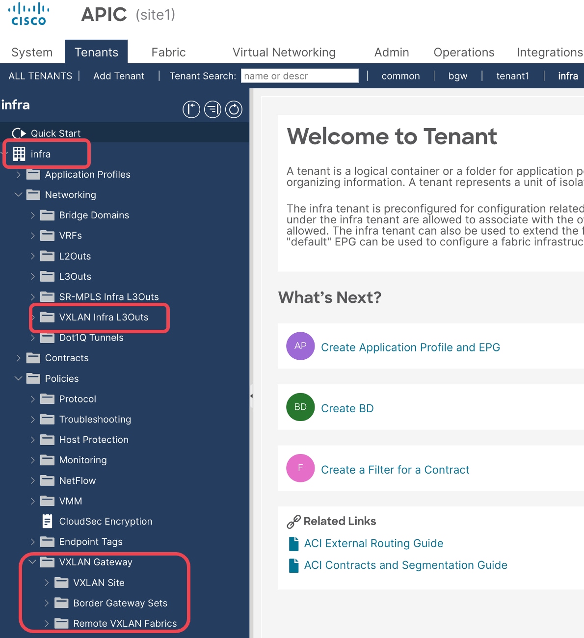
Figure 6. Infra tenant VXLAN Infra L3Outs and VXLAN Gateway
● VXLAN Infra L3Outs: This serves as the foundational “underlay” connection, used to connect ACI Border Gateways (BGWs) to the Inter-Site Network (ISN). The VXLAN Infra L3Out is associated with a Border Gateway Set, an object representing a group of ACI Border Gateways part of the same fabric, to signal that these gateways should utilize this specific Infra L3Out for overlay connectivity.
● VXLAN Gateway: This sub-menu under Policies contains the logical configuration required to represent the ACI site as a “site” within a broader VXLAN EVPN ecosystem. It consists of three key objects:
◦ VXLAN Site: Defines the local ACI site as a unique EVPN site. It requires a site ID, which ensures the site is uniquely identified when exchanging routes with remote sites, thereby preventing routing loops.
◦ Border Gateway Sets: This object represents the collection of all Border Gateways within the ACI site. In a Multi-Pod environment, Border Gateways must be deployed in each pod. As an administrator, you must assign a unique External Anycast (External Data Plane IP also known as Multi-Site external VIP) to the Border Gateways in each pod. For example, if you have two pods with Border Gateways, you must assign two separate External Anycast IP addresses, one for each pod’s group of Border Gateways. This External Anycast IP acts as the destination tunnel endpoint for remote VXLAN sites communicating with the ACI site. Note that there is only one Border Gateway Set per site. Additionally, the APIC automatically assigns a unique Internal Anycast IP to all Border Gateways in the site for internal data plane communication within the ACI site. The Border Gateway Set is then linked to the Remote VXLAN Sites configuration.
◦ Remote VXLAN Sites: Defines the external VXLAN EVPN sites you wish to interconnect with. For instance, from the perspective of ACI site 1, ACI site 2 is defined as a Remote VXLAN site. This is where you specify reachability information, such as the remote site’s BGW loopback IP addresses, to establish the EVPN Multi-Site relationship. Starting from ACI releases 6.1(6) and 6.2(2), this same configuration is also used to define connectivity to a Route-Server, providing an alternative to full-mesh BGP EVPN peering between Border Gateways.
In this example, the underlay BGP configuration on the ISN device is configured manually via Cisco NX-OS CLI. For each ACI site, the underlay configuration is done using the APIC GUI. Detailed steps, including screenshots, will be provided in the following sections.
Inter-Site Network Configuration - Underlay
The figure below shows the IP addresses and interfaces used in the underlay BGP configuration example.
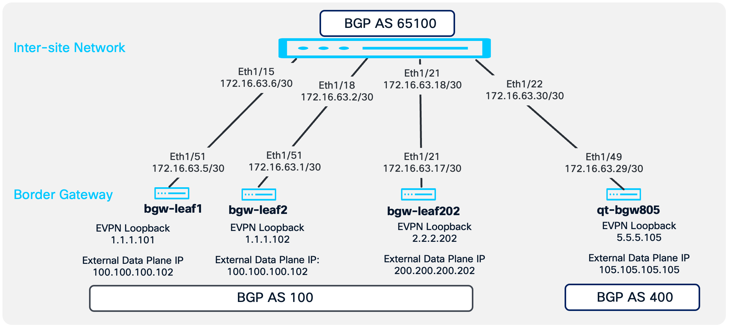
Figure 7. ISN Underlay IP addressing
To provide underlay connectivity between the two sites to communicate using VXLAN BGP EVPN, the ISN devices must provide a routed transport to carry the EVPN control plane and VXLAN date plane. To accommodate this, each ISN device will have the BGP enabled, and will peer eBGP to Border Gateways in both ACI sites. This ensures that any IP address injected from each site will automatically be advertised to the other sites and allow IP reachability to be established. Although this reference topology uses single ISN device to represent ISN network, it is recommended to use at least two ISN devices for redundancy.
The following outlines the primary configuration steps on the ISN device which is Cisco Nexus 9000 running NX-OS. Note that object names, such as VRF, are provided for reference only; you should employ names consistent with your network’s naming conventions.
Proceed with the following key configuration steps on the ISN device.
● If the ISN device is shared between other function, it is recommended to create a dedicated VRF for inter-site control plane and data plane traffic forwarding.
● Assign IP addresses and the relevant VRF to the physical interfaces connecting the ISN device to the Border Gateways of each site.
● Configure BGP and establish BGP peers with the Border Gateways of each site, and between individual Border Gateways, using the appropriate Autonomous System Numbers.
The sample configuration below uses routed physical interfaces on the ISN to connect to the Border Gateways. If the use of routed sub-interface is preferred, any appropriate VLAN ID can be used; the commonly referenced VLAN 4 is supported but not required.
# Create a VRF
vrf context bgw
address-family ipv4 unicast
# Interface configuration
interface Ethernet1/15
description --> bgw-leaf1 51
mtu 9216
vrf member bgw
ip address 172.16.63.6/30
no shutdown
interface Ethernet1/18
description --> bgw-leaf2 e1/52
mtu 9216
vrf member bgw
ip address 172.16.63.2/30
no shutdown
interface Ethernet1/21
description bgw-leaf202 e1/21
mtu 9216
vrf member bgw
ip address 172.16.63.18/30
no shutdown
interface Ethernet1/22
description --> qt-bgw-805
mtu 9216
vrf member bgw
ip address 172.16.63.30/30
no shutdown
# BGP configuration
router bgp 65100
vrf bgw
neighbor 172.16.63.1
remote-as 100
update-source Ethernet1/18
address-family ipv4 unicast
neighbor 172.16.63.5
remote-as 100
update-source Ethernet1/15
address-family ipv4 unicast
neighbor 172.16.63.17
remote-as 100
update-source Ethernet1/21
address-family ipv4 unicast
neighbor 172.16.63.29
remote-as 400
update-source Ethernet1/22
address-family ipv4 unicast
ACI VXLAN L3Out – VXLAN Gateway
The followings are the pre-requisite and steps to configure VXLAN L3Out that is an infra L3Out object to build underlay BGP peering from ACI Border Gateway to ISN device.
● Make sure ACI leaf nodes are registered with Border Gateway role
● In the infra tenant, create a VXLAN L3Out to do underlay BGP peering with ISN devices
ACI releases 6.1(6) and 6.2(2) add support for the Border Gateway Route Server, which streamlines the BGP overlay control plane by reducing the required number of overlay BGP sessions. This model uses overlay BGP EVPN sessions between the ACI Border Gateways and Route Servers, providing an alternative to full-mesh inter-site overlay BGP EVPN peering between Border Gateways. Configuration steps and best practices are covered at the end of this section.
Border Gateway is new role; we need to explicitly register the leaf with Border Gateway role. If the leaf had been already registered with leaf role, it must be decommissioned and re-registered with Border Gateway role. The leaf will be displayed with the Node Type “Border Gateway Leaf” in the fabric inventory.
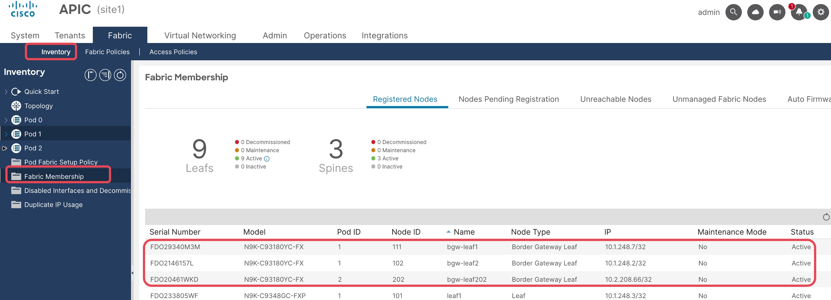
Figure 8. ACI Site 1 Inventory Fabric Membership
ACI Site 1 - Border Gateway Sets
At the time of writing, only one Border Gateway Set is permitted per site. As an APIC administrator, you must manually define a unique External Data Plane IP Address for each ACI Pod. The External
Data Plane IP is an anycast IP address shared by all Border Gateways within the same Pod. Also known as the Multi-Site External VIP, this IP address has the following properties and purposes:
● Used as the next-hop for Type-2 and Type-5 EVPN routes advertised to remote VXLAN EVPN fabrics.
● Serves as the destination IP for Layer 2 and Layer 3 communications initiated from the VXLAN EVPN domain toward endpoints or external networks via ACI fabric.
● Has a unique value per Pod.
The Internal Anycast IP Address (Internal Anycast TEP) is automatically assigned by the APIC to all Border Gateways within the same ACI site. Also known as the Multi-Site Internal VIP, this Internal Anycast IP address has the following properties and purposes:
● Used as the source IP for all traffic received from the remote ACI sites and re-encapsulated to be sent into the ACI fabric.
● Used as the destination IP for all traffic destined to remote endpoints that are part of stretched BDs.
● Assigned as a common value to all ACI Border Gateways within the same site (regardless of single Pod or Multi-Pod).
The Border Gateway Set is associated with the Remote VXLAN Sites object, which is configured in the following step.
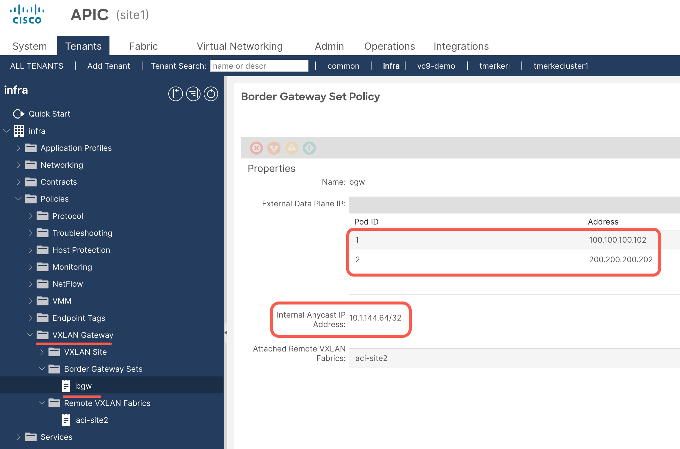
Figure 9. ACI Site 1 Border Gateway Sets
To create a Border Gateway Set, navigate to Policies -> VXLAN Gateway in the infra tenant. Right-click on Border Gateway Sets and select Create Border Gateway Set Policy. A workflow will open to guide you through the creation process. Once the set is created, it can be used in the VXLAN Infra L3Out creation workflow to reference the Border Gateway Set to the VXLAN Infra L3Out.
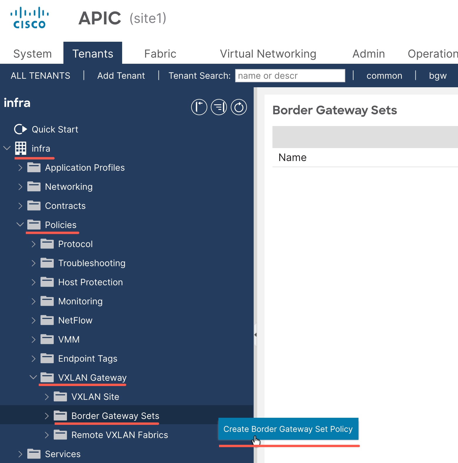
Figure 10. Create a Border Gateway Set Policy
ACI Site 1 - VXLAN Infra L3Outs
Upon joining the fabric, the Border Gateway, like any other leaf switch, automatically obtains a router ID from the ACI site’s TEP pool (in this example, 10.1.248.7 for the first Border Gateway). This router ID is used for the MP-BGP sessions to the spines and is referred to as the Operational Router ID.
When configuring the VXLAN Infra L3Out, it is recommended to leave the Router ID field blank to retain the existing Router ID. In this case, the Router ID field will display as 0.0.0.0, while the actual router ID, referred to as the Operational Router ID (10.1.248.7), remains in use. While it is technically possible to configure a different router ID, doing so will cause the existing MP-BGP sessions on the Border Gateway to flap.
When configuring a node profile, you can specify the loopback interface under the node. The IP address assigned to the loopback interface on the Border Gateway is used to establish BGP EVPN control plane peering with Border Gateways in other ACI sites or with a Route Server.
To create VXLAN Infra L3Out, from infra tenant, navigate to Networking, right click on VXLAN Infra L3Outs.
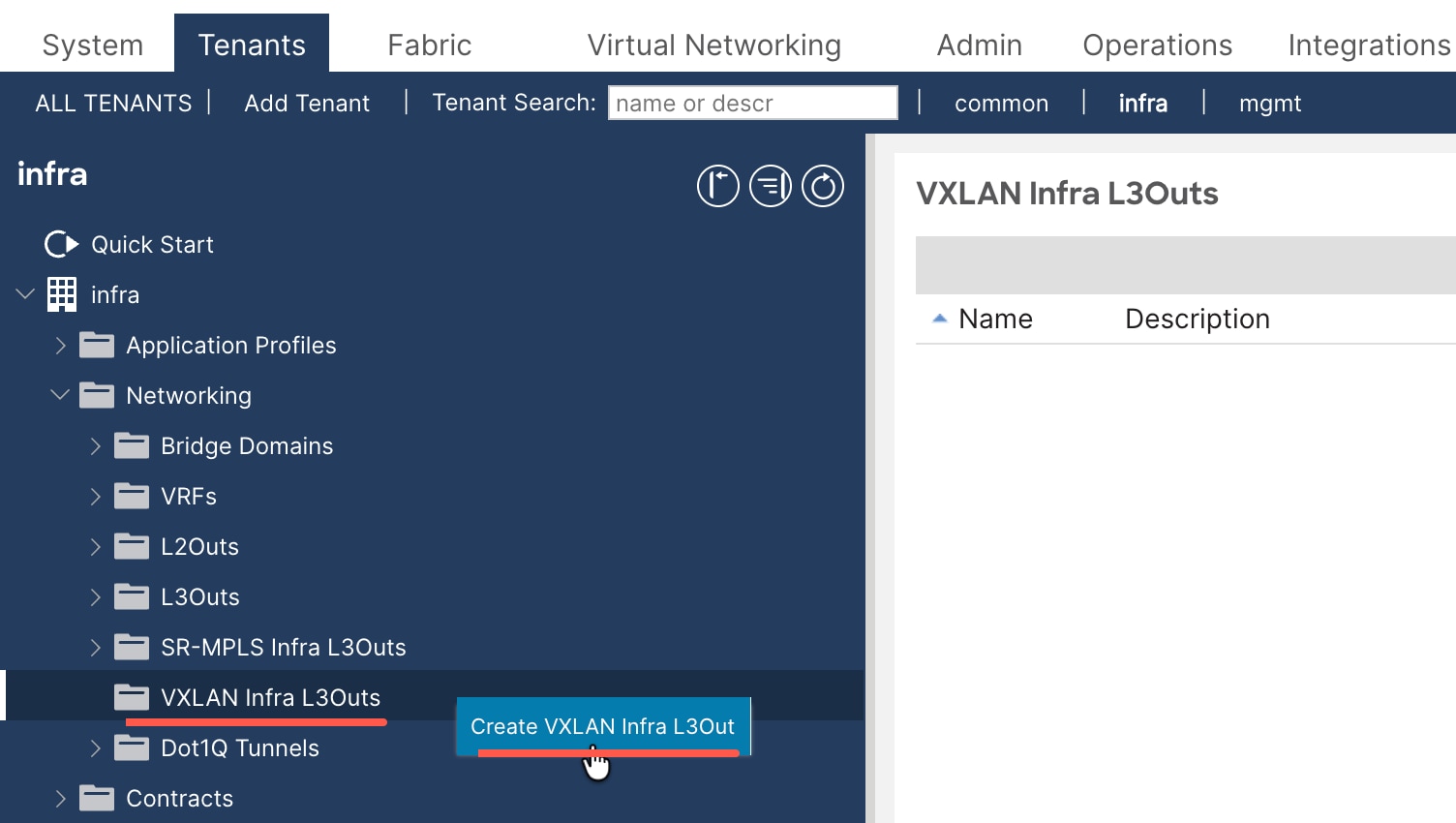
Figure 11. Create a VXLAN Infra L3Out
Give it a name for example vxlan-infra and hit Next to continue.
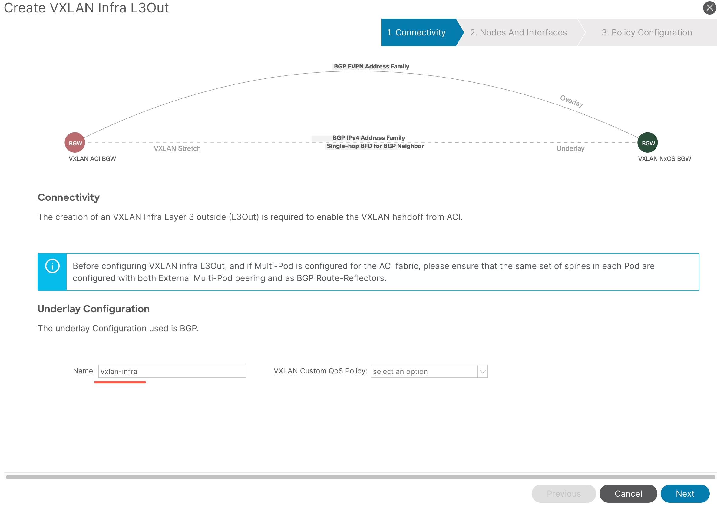
Figure 12. VXLAN Infra L3Out vxlan-infra
Choose a Border Gateway from the Node ID drop-down list. A warning message appears with additional information about the Operational Router ID. Click OK to continue.
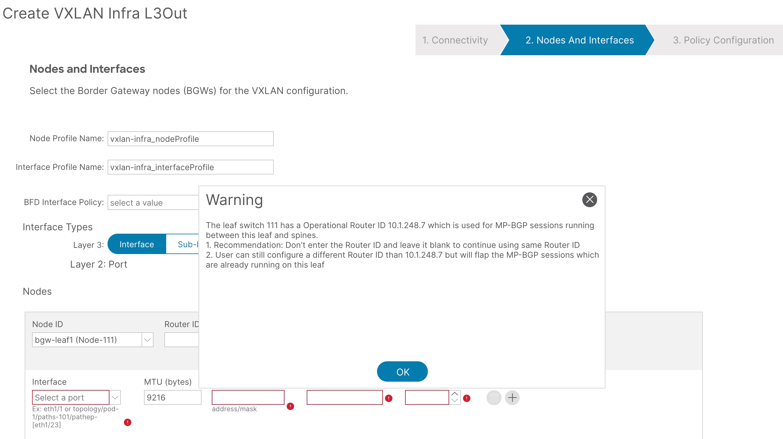
Figure 13. VXLAN Infra Operational Router ID
Configure the following fields:
● Node Profile name
● Interface Profile name
● Loopback Address: The source IP address used to establish the BGP EVPN control plane to remote Border Gateways or a Route Server.
● Interface IPv4 address: The IP address of the local interface.
● Peer IPv4 Address: The IP address of the connected ISN interface.
● Remote ASN: The BGP ASN of the ISN device.
● MTU: Use the default value 9216
This example uses a routed interface, but routed sub-interfaces are also supported. Any VLAN ID can be used for routed sub-interfaces, there is no requirement to use VLAN 4, which is required for spine uplinks in ACI Multi-Pod and Multi-Site deployments. The Border Gateway must use a downlink port to connect to the ISN device. Default uplink ports are intended for connectivity to the ACI spines; however, if needed, an uplink port can be converted to a downlink port and used for ISN connectivity. To add more interfaces, click the + button. Once complete, click Next to continue.
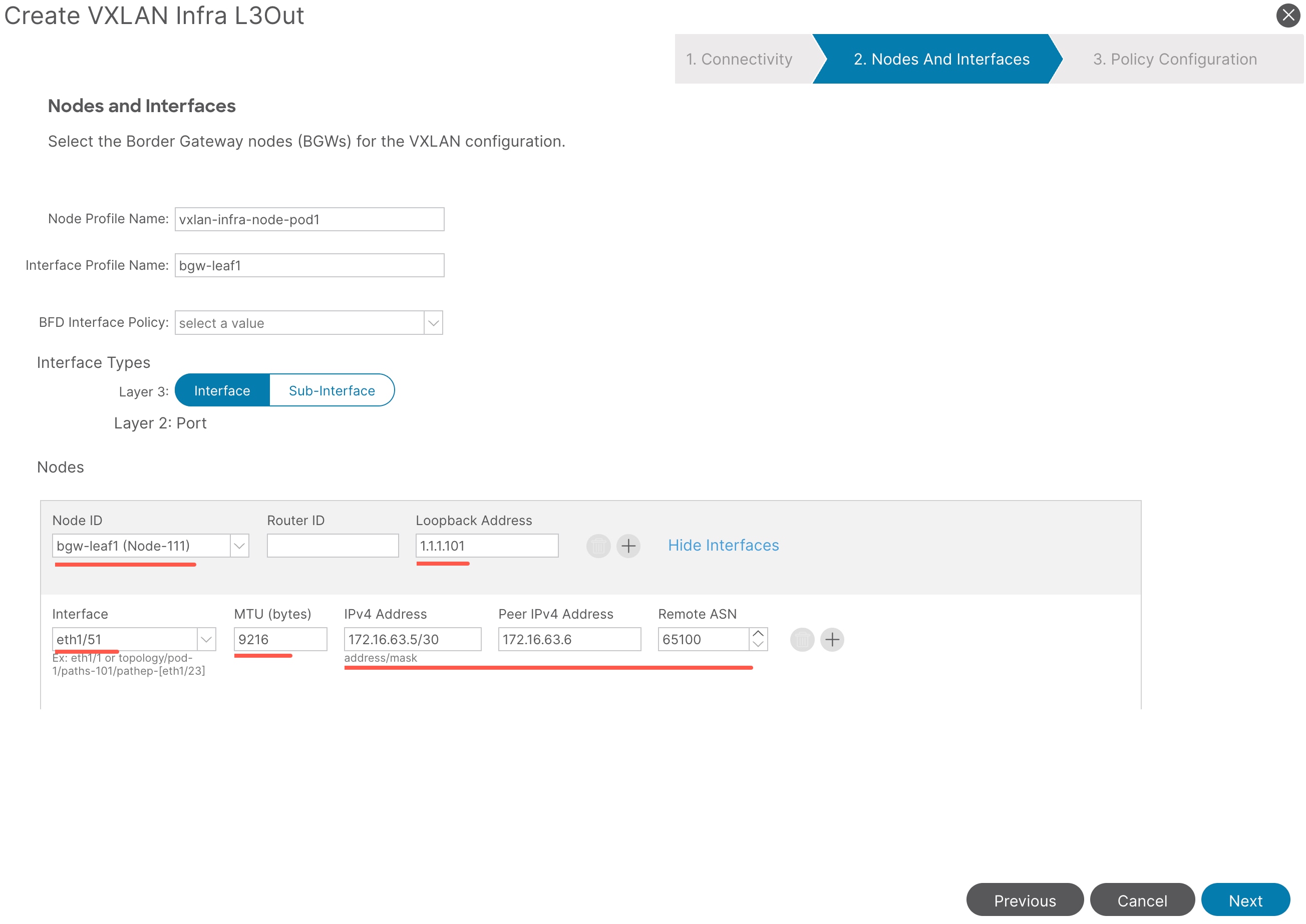
Figure 14. VXLAN Infra L3Out node, interface profile, peer.
On the next screen, select the Border Gateway Set created in the previous step and click Finish to complete the configuration. You may check the “Configure VXLAN Remote Fabrics” checkbox to proceed a VXLAN Remote Fabric configuration in the same wizard.
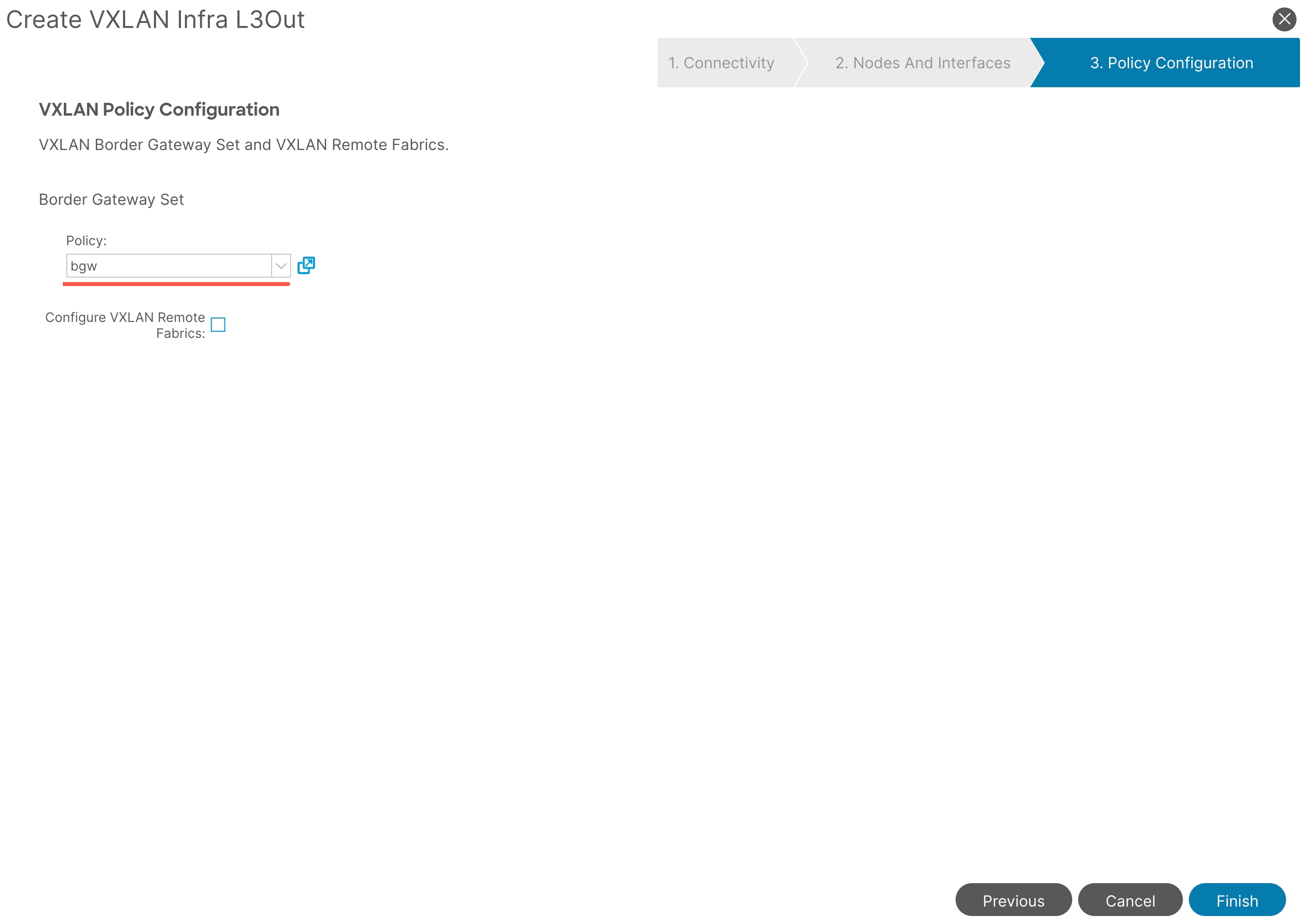
Figure 15. VXLAN Infra L3Out Attach Border Gateway Set
If a Border Gateway Set has not yet been created, click the dropdown list and select “Create Border Gateway Set Policy” to launch the creation workflow. Once a Border Gateway Set is created, the configuration workflow returns to this main window.
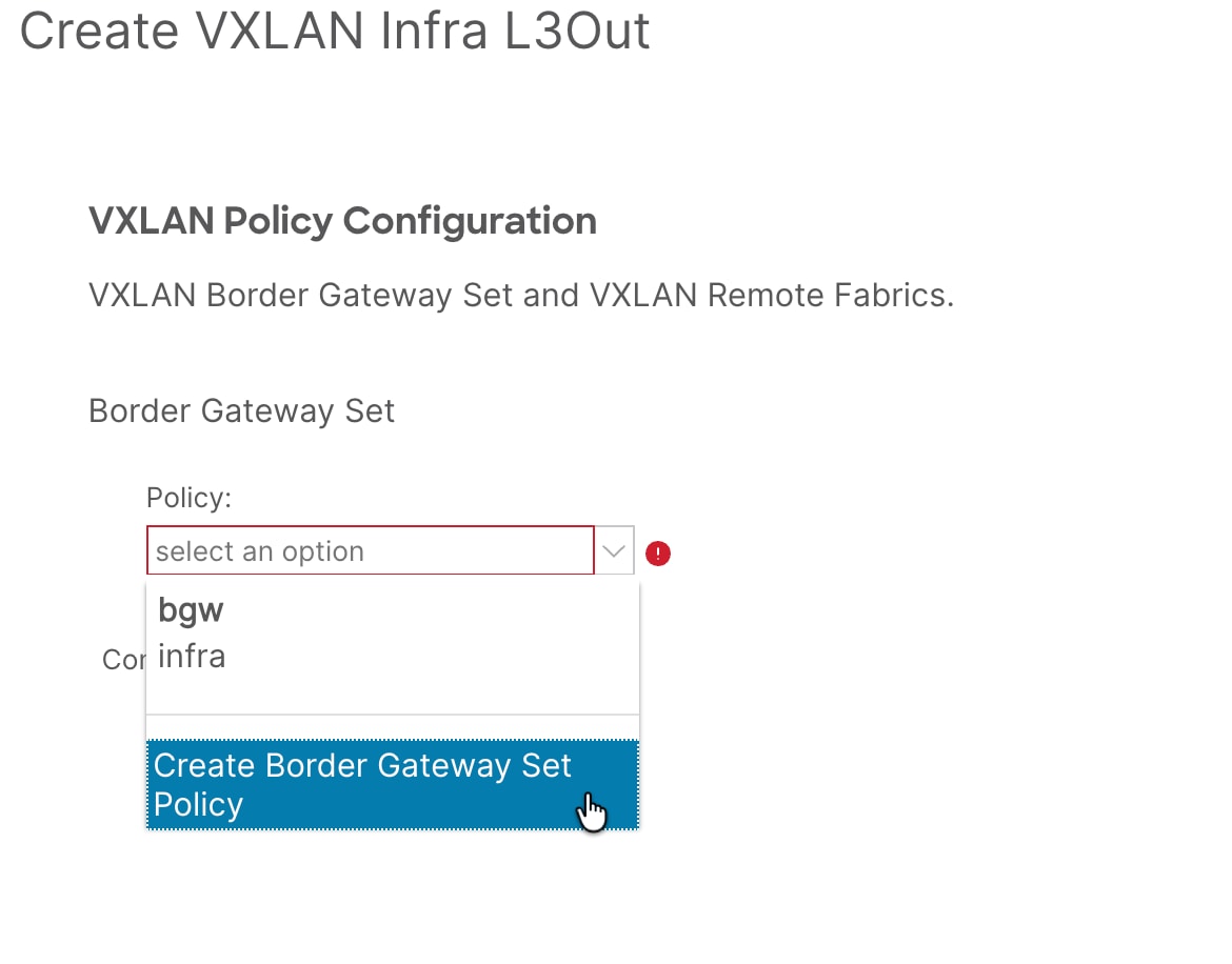
Figure 16. Create Border Gateway Set inside VXLAN Infra L3Out creation workflow.
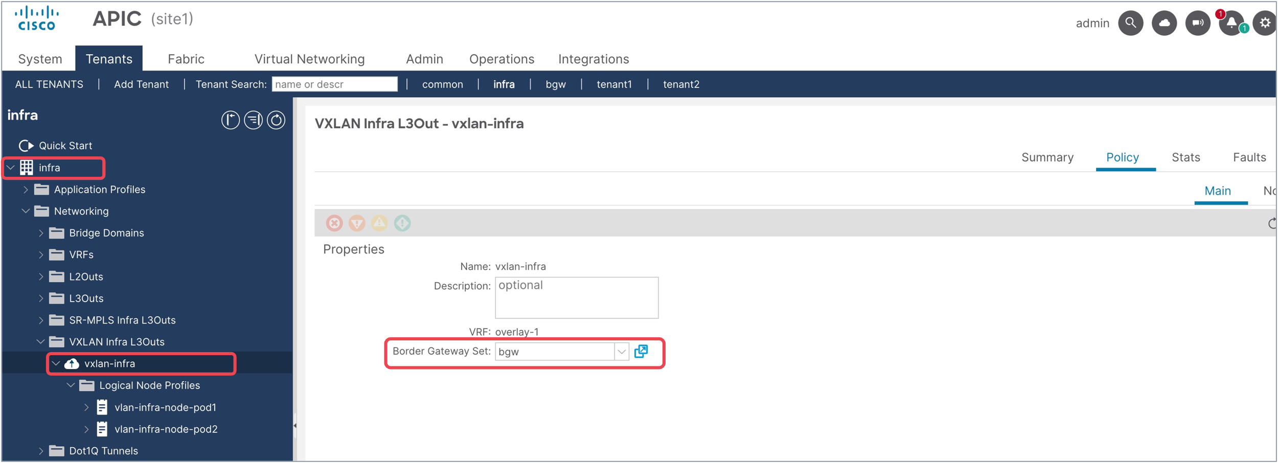
Figure 17. VXLAN Infra L3Out
The figure above shows the completed VXLAN Infra L3Out object and its Border Gateway Set Policy. This set represents all Border Gateways in the site. You can define the set during the VXLAN L3Out creation workflow or later in the Policy tab. However, the VXLAN Infra L3Out must be attached to a Border Gateway Set Policy to successfully create the overlay EVPN session. The next screenshots show completed objects including node profiles, interface profiles.
ACI Site 1 - Border Gateway Node Profiles
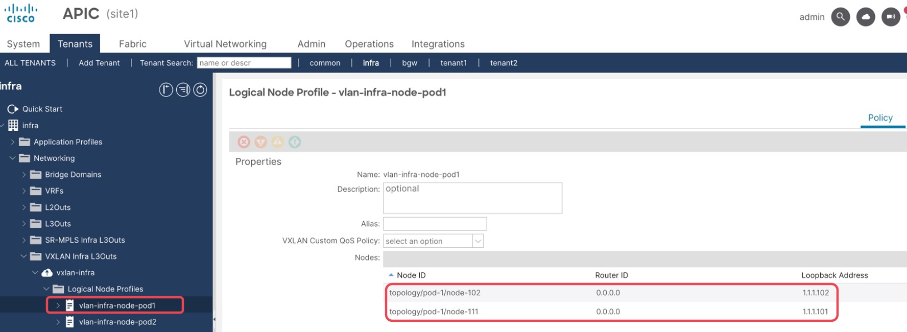
Figure 18. ACI Site 1 BGW Logical Node Profile
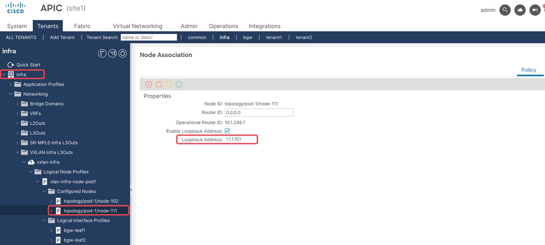
Figure 19. ACI Site 1 bgw-leaf1 Node Association
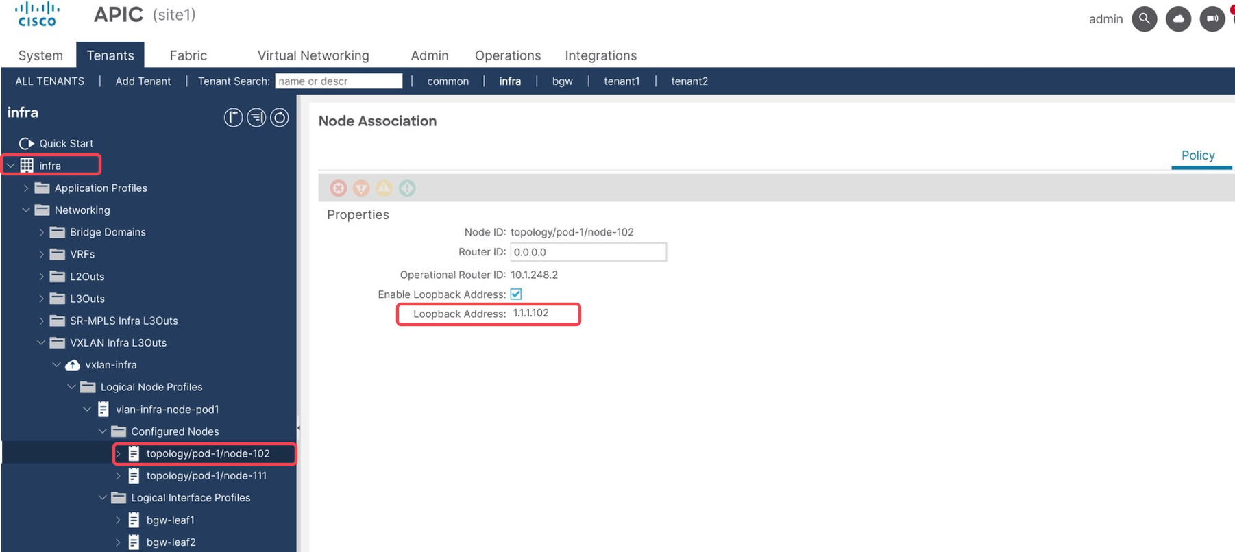
Figure 20. ACI Site 1 bgw-leaf2 Node Association
ACI Site 1 - Border Gateway Interface Profiles
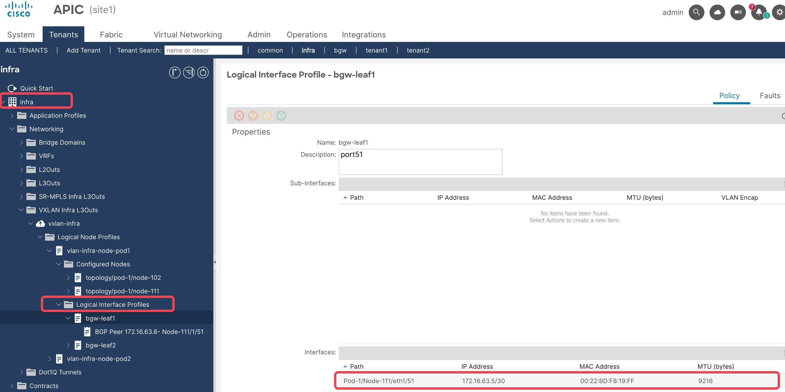
Figure 21. ACI Site 1 Border Gateway bgw-leaf1 Logical Interface Profile
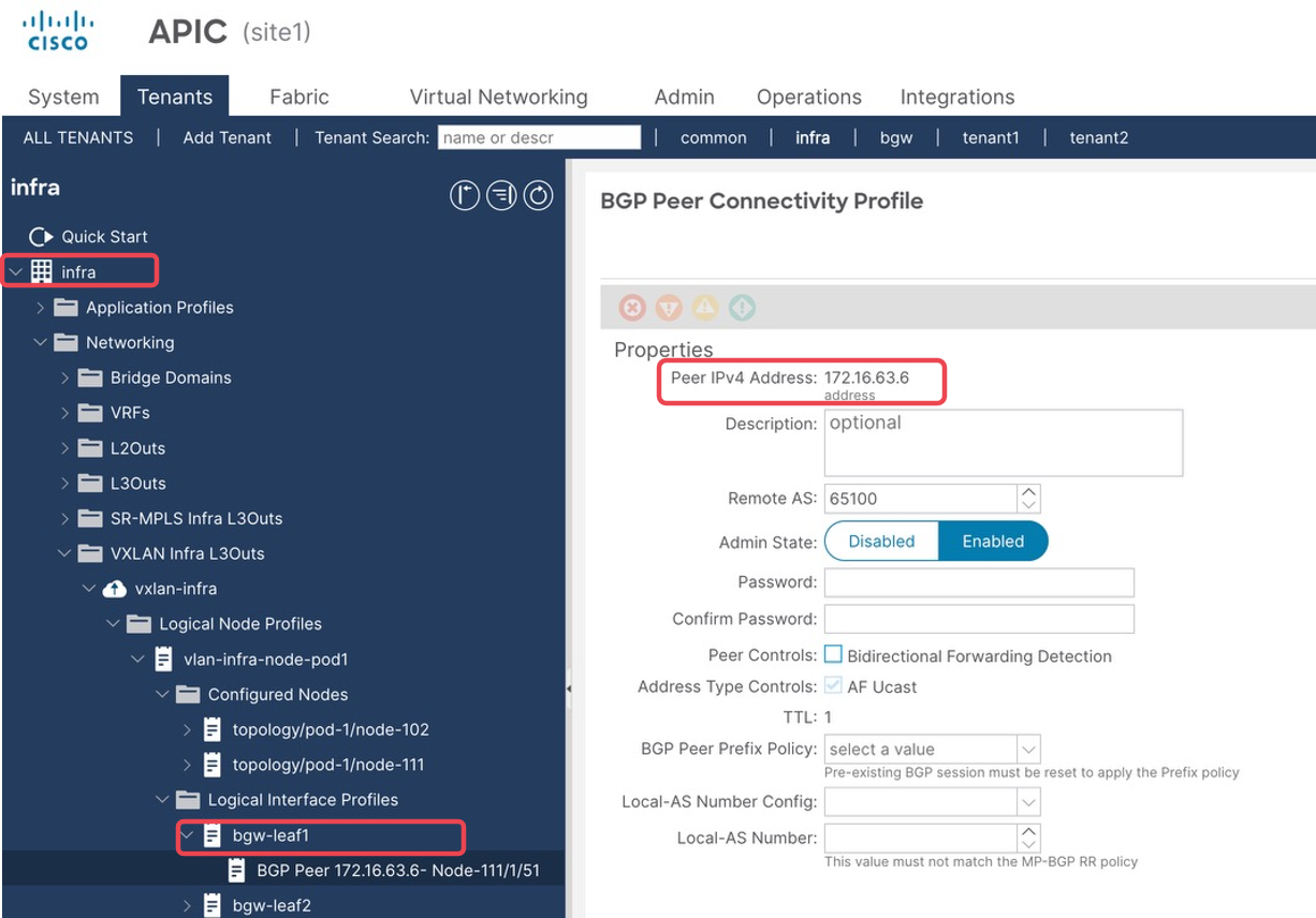
Figure 22. ACI Site 1 Border Gateway bgw-leaf1 BGP Peer Connectivity Profile
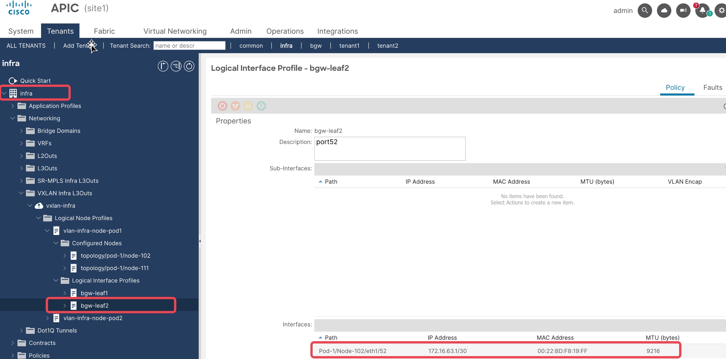
Figure 23. ACI Site 1 Border Gateway bgw-leaf2 Logical Interface Profile
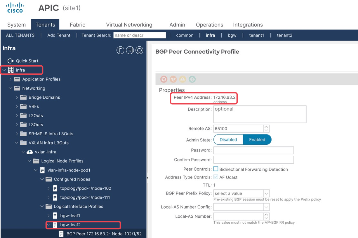
Figure 24. ACI Site 1 Border Gateway bgw-leaf2 BGP Peer Connectivity Profile
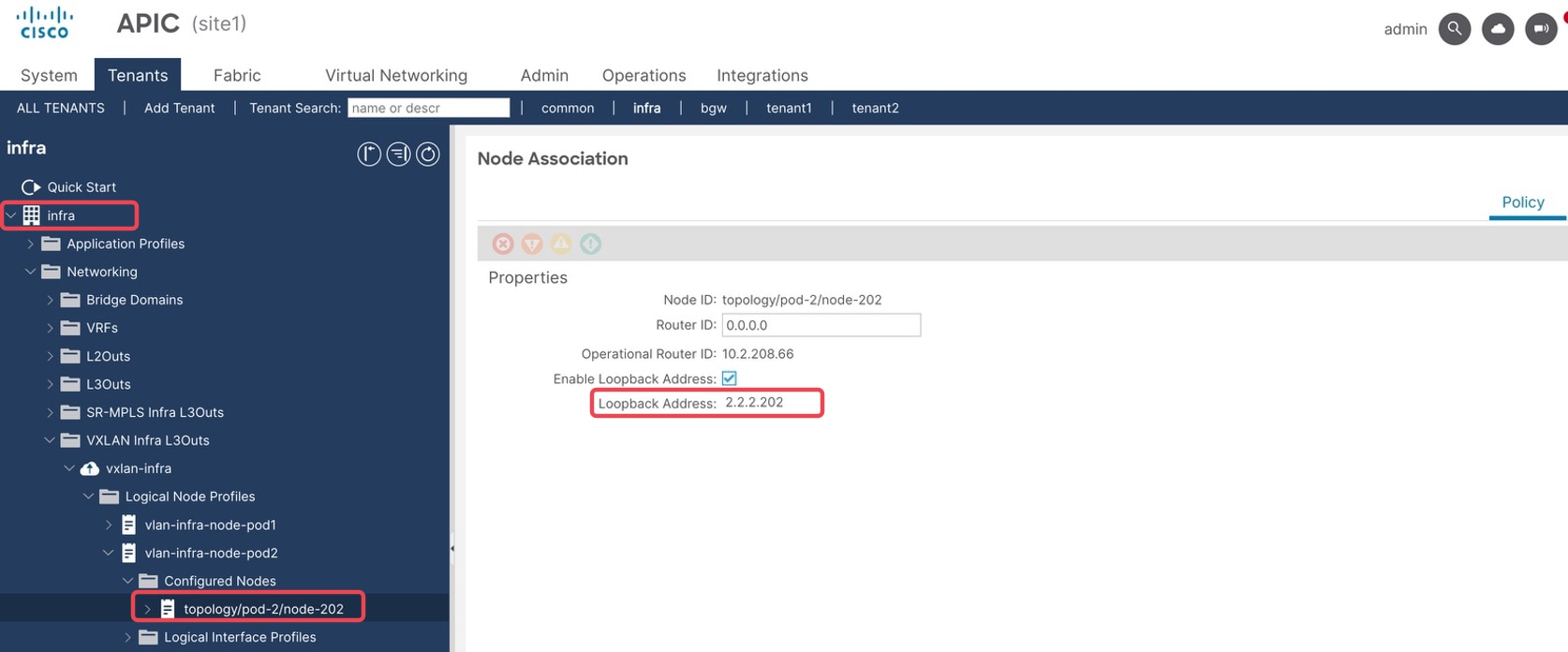
Figure 25. ACI Site 1 bgw-leaf202 (in pod2) Node Association
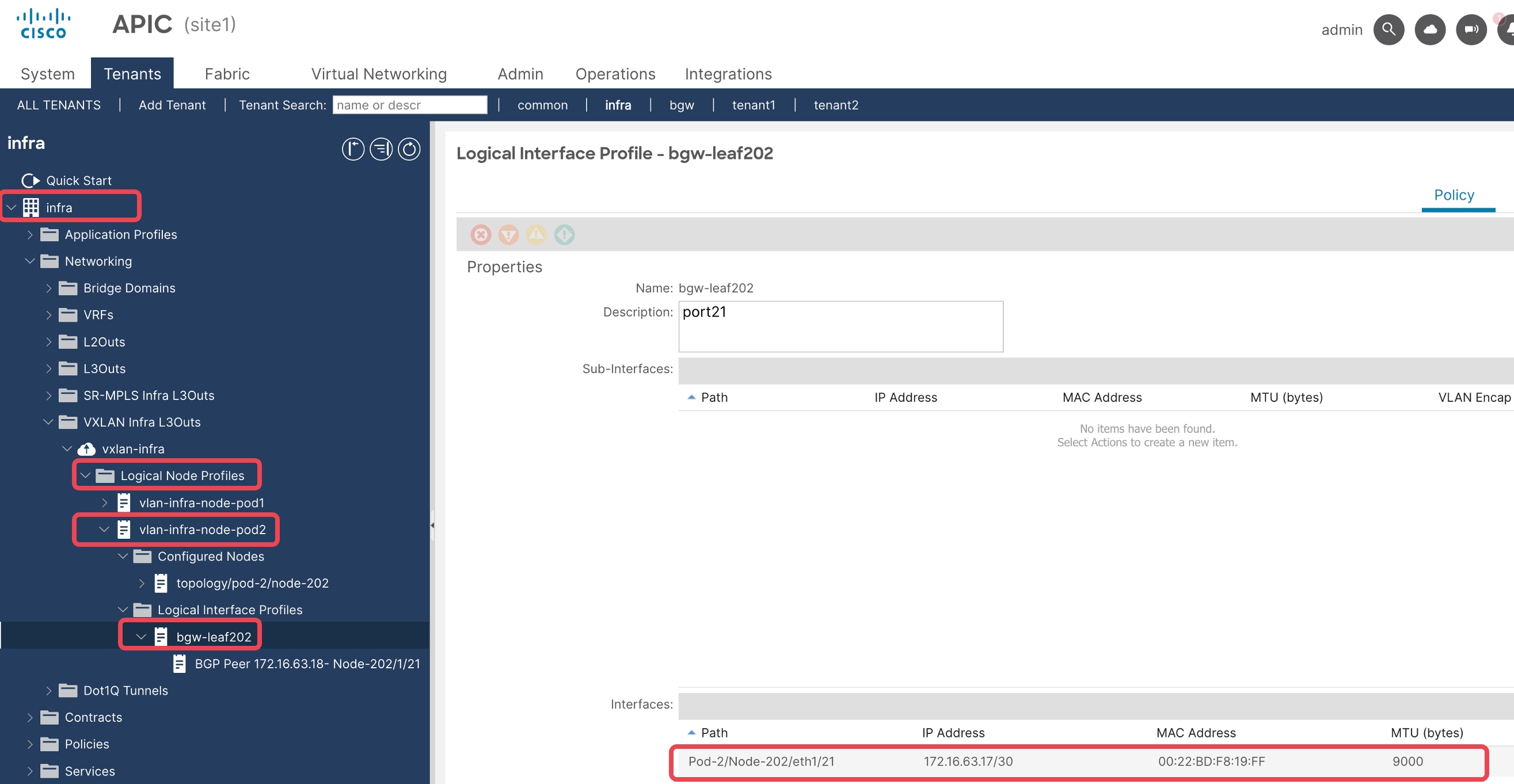
Figure 26. ACI Site 1 bgw-leaf202 (in pod2) Logical Interface Profile
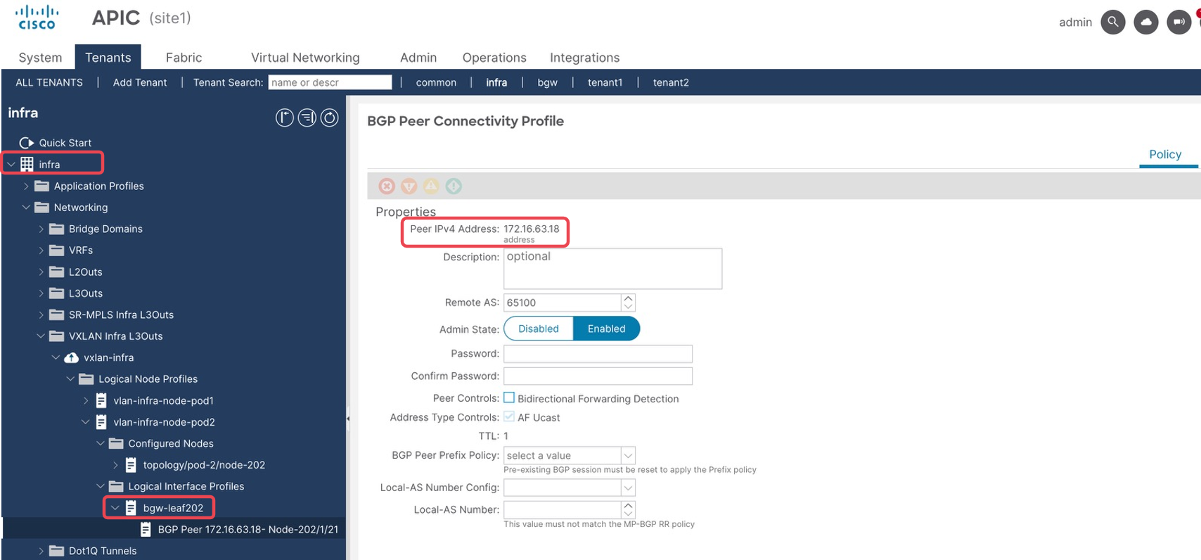
Figure 27. ACI Site 1 bgw-leaf202 (in pod2) BGP Peer Connectivity Profile
The VXLAN Site object uniquely identifies the local site, which in this example is ACI Site 1 (site1). At the time of writing, only one VXLAN Site is permitted per site; therefore, the APIC UI prevents the creation of a new VXLAN Site if one already exists. It is a common practice to use the BGP Autonomous System Number (ASN) as the Site ID though it is not mandatory.
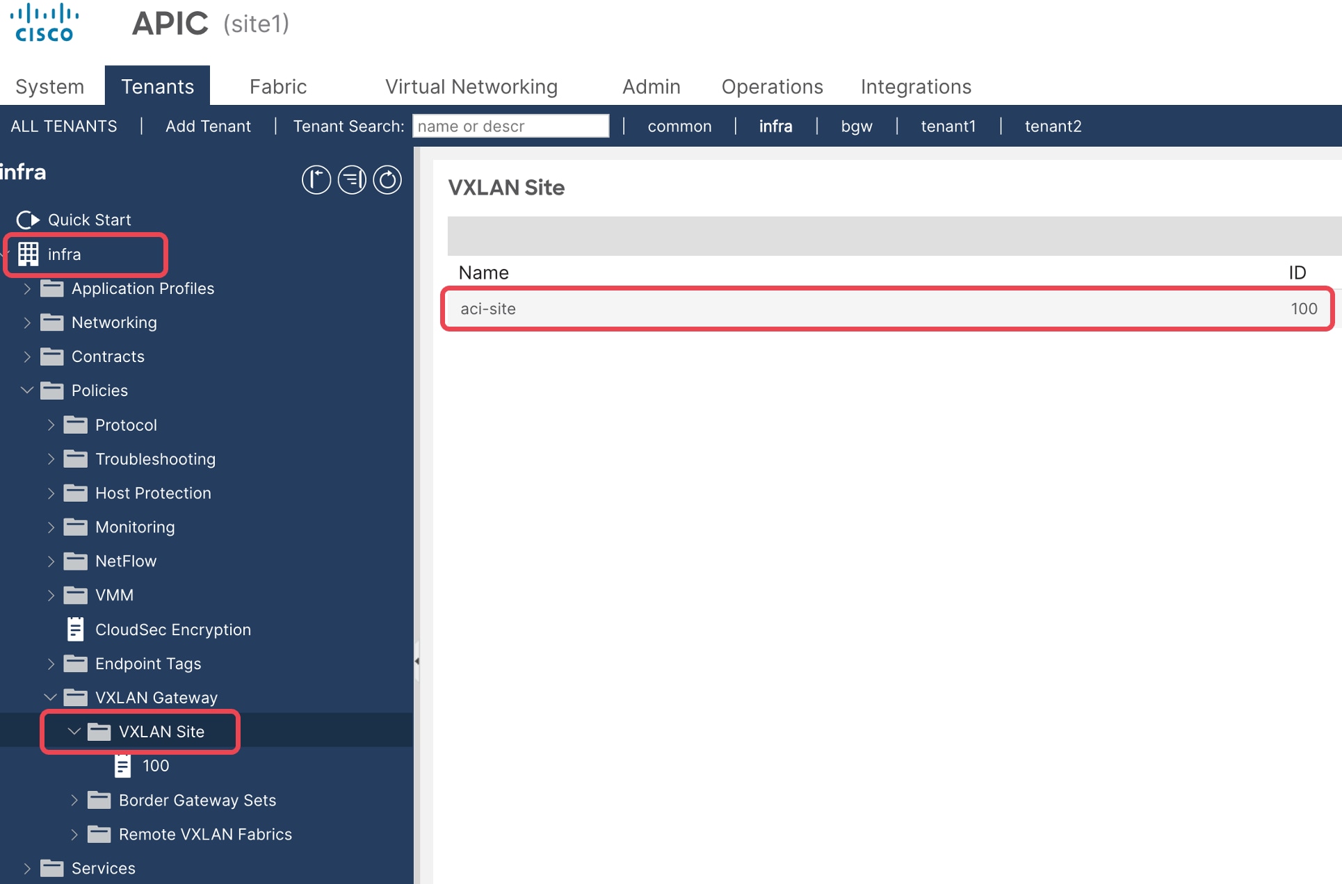
Figure 28. ACI Site 1 VXLAN Site
ACI Site 1 - Remote VXLAN Sites
The Remote VXLAN Sites object (displayed as Remote VXLAN Fabrics in the APIC GUI) defines the external site to which local ACI site (site1 in this example) will connect. In this step, specify the Peer IP Address (5.5.5.105 in this example), which is the loopback address of the Border Gateway in the remote site (ACI site2).
The Remote VXLAN Sites object is also used to define a Route Server, enabling all ACI site Border Gateways to establish BGP EVPN control plane peering to the Route Server. This eliminates the need for direct peering between Border Gateways across sites.
As an APIC administrator, you must also associate the Remote VXLAN Site with the local Border Gateway Set to complete the configuration.
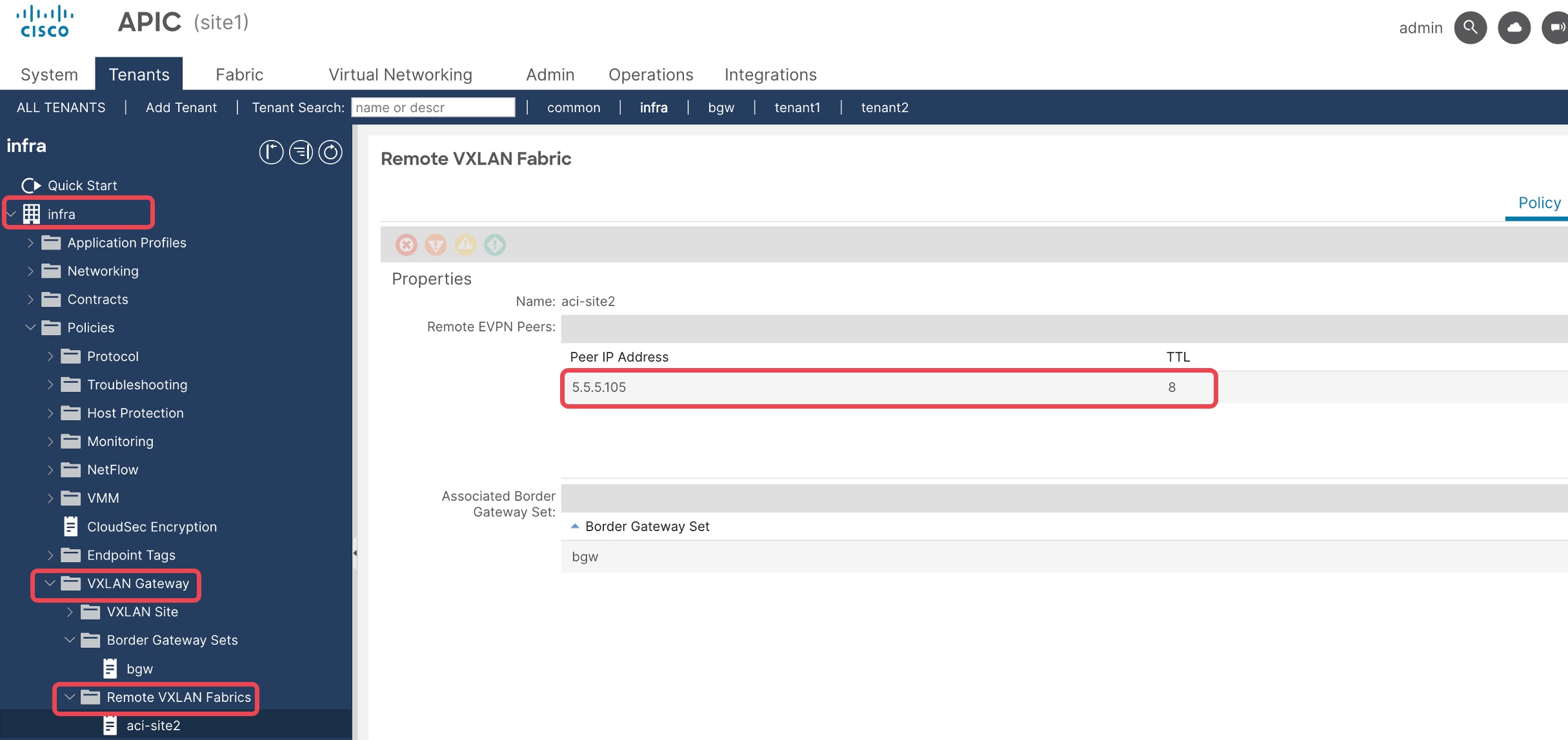
Figure 29. ACI Site 1 Remote VXLAN Fabric
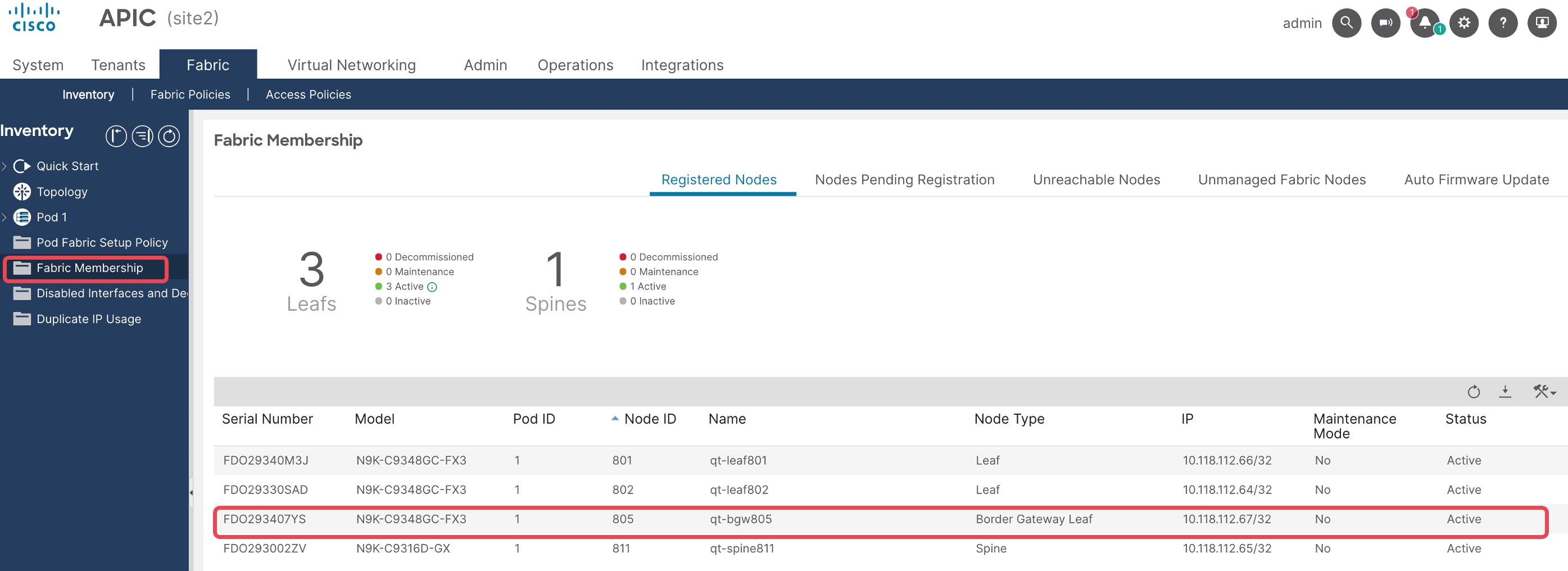
Figure 30. ACI Site 2 Inventory – Fabric Membership
ACI Site 2 - Border Gateway Sets
Since ACI Site 2 (site2) is a single-pod site, only one External Data Plane IP needs to be configured.
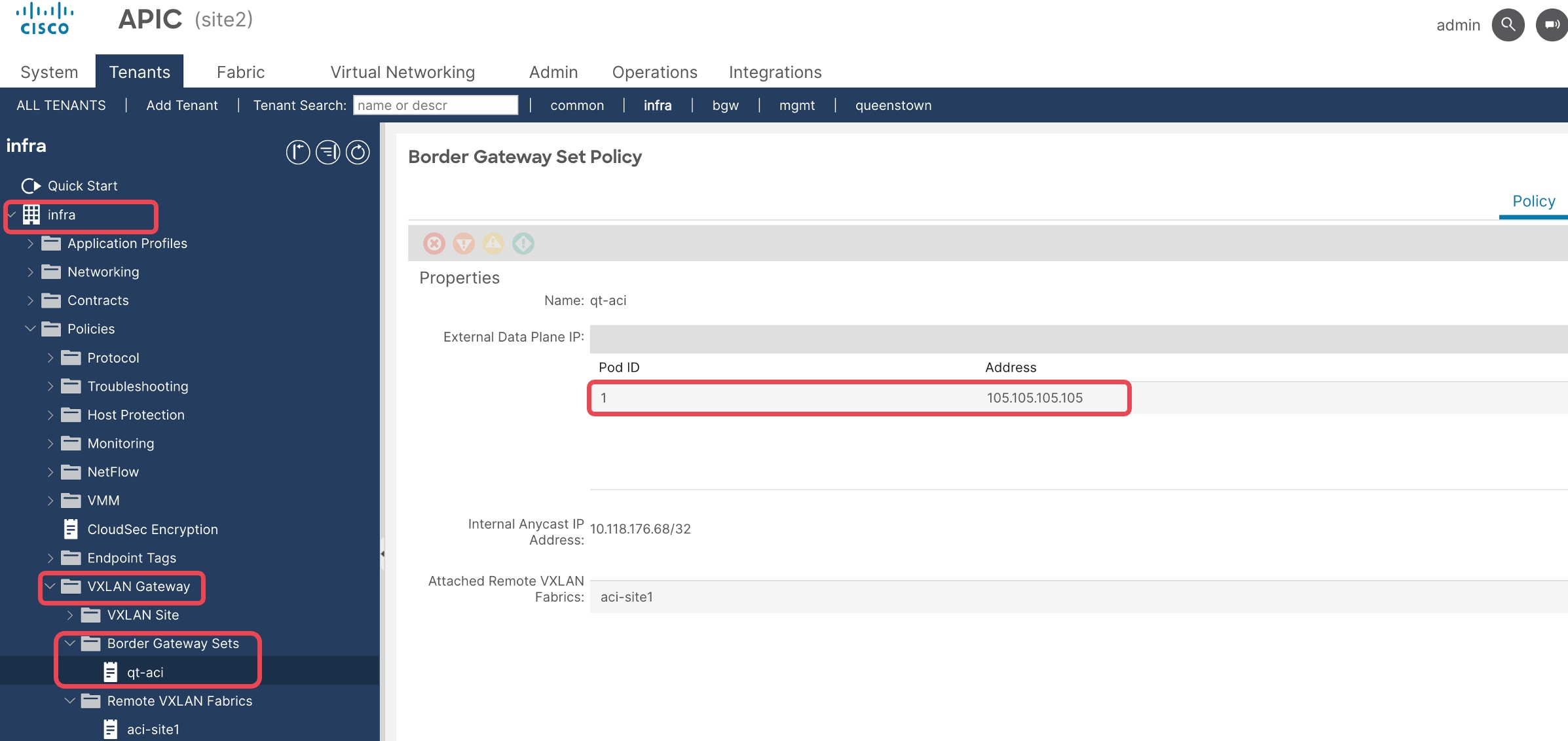
Figure 31. ACI Site 2 Border Gateway Sets
ACI Site 2 - VXLAN Infra L3Outs
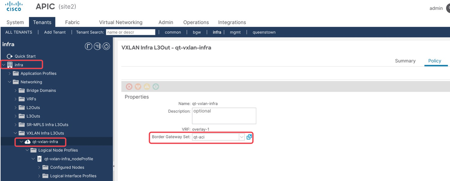
Figure 32. ACI Site 2 VXLAN Infra L3Outs
ACI Site 2 - Border Gateway Node Profiles
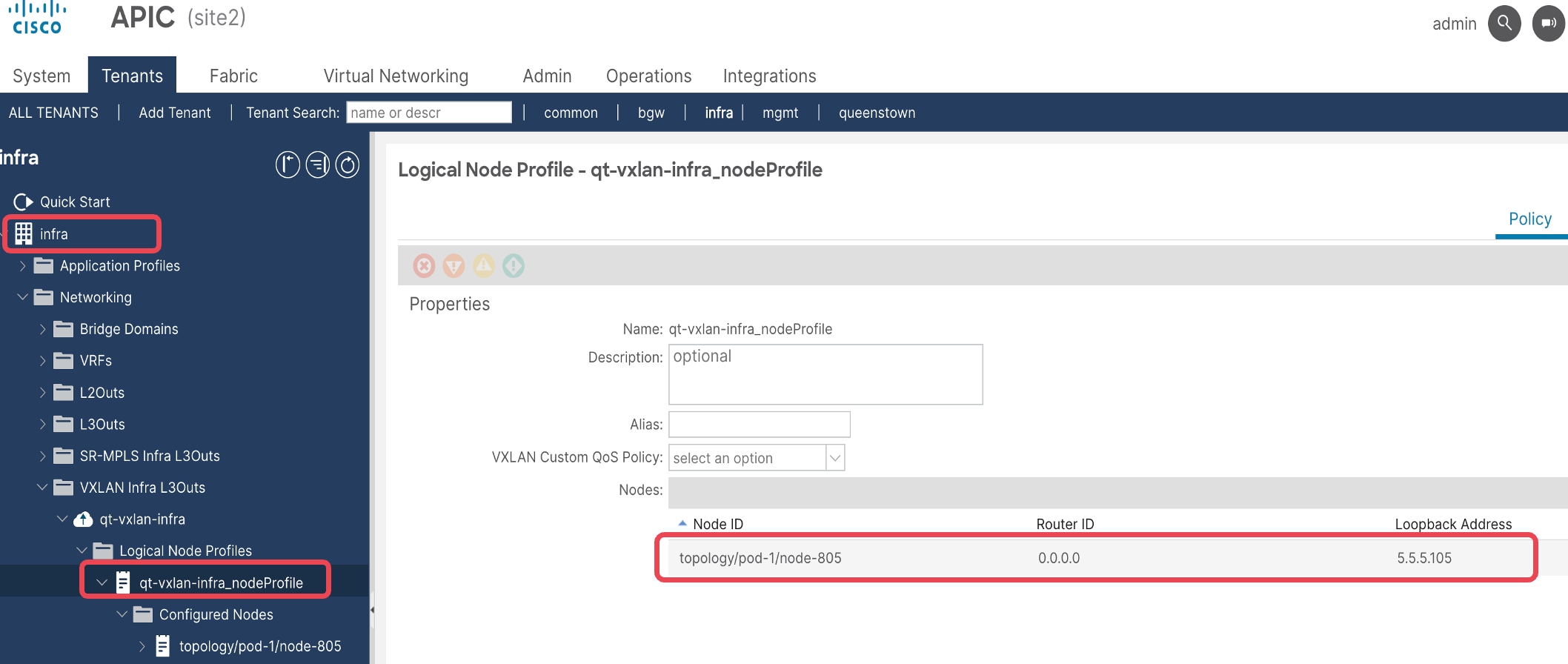
Figure 33. ACI Site 2 Border Gateway qt-bgw805 Logical Node Profile
ACI Site 2 - Border Gateway Interface Node Profiles
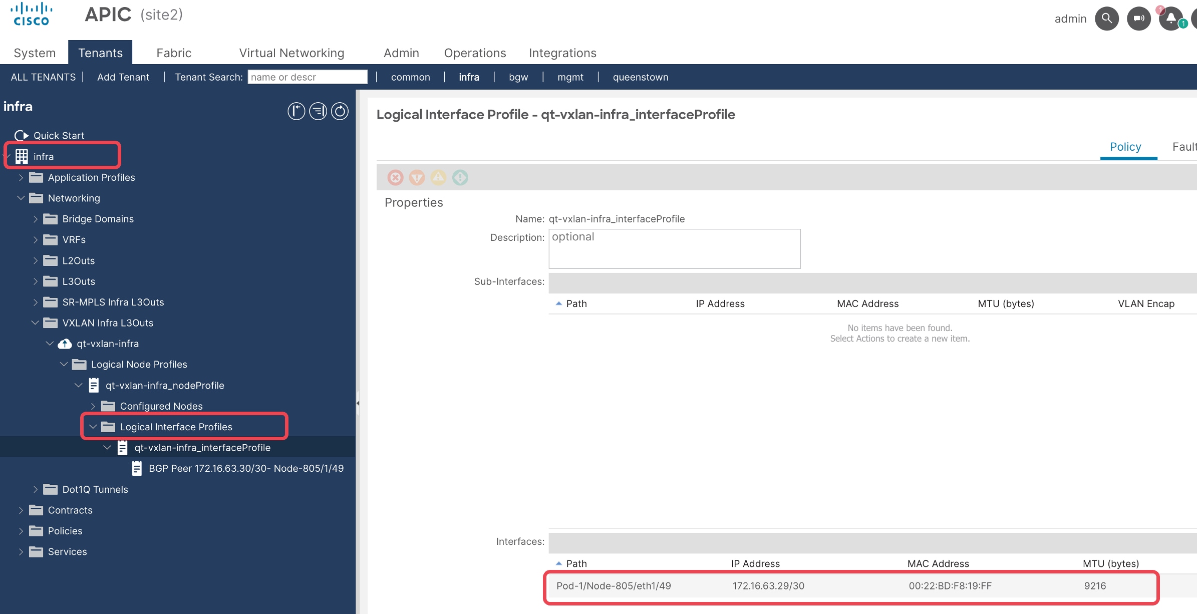
Figure 34. ACI Site 2 Border Gateway - Logical Interface Profile
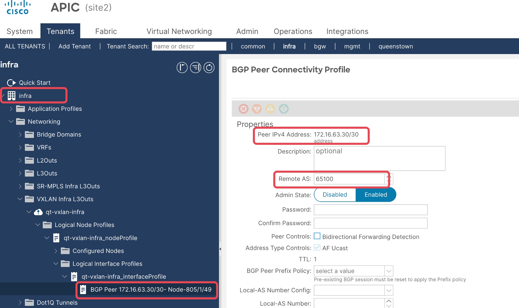
Figure 35. ACI Site 2 Border Gateway qt-leaf805 BGP Peer Connectivity Profile
The VXLAN Site can be assigned any descriptive name; in this example, the site representing ACI Site 2 is named qt-site. It is common practice to use the BGP Autonomous System Number (ASN) as the Site ID.
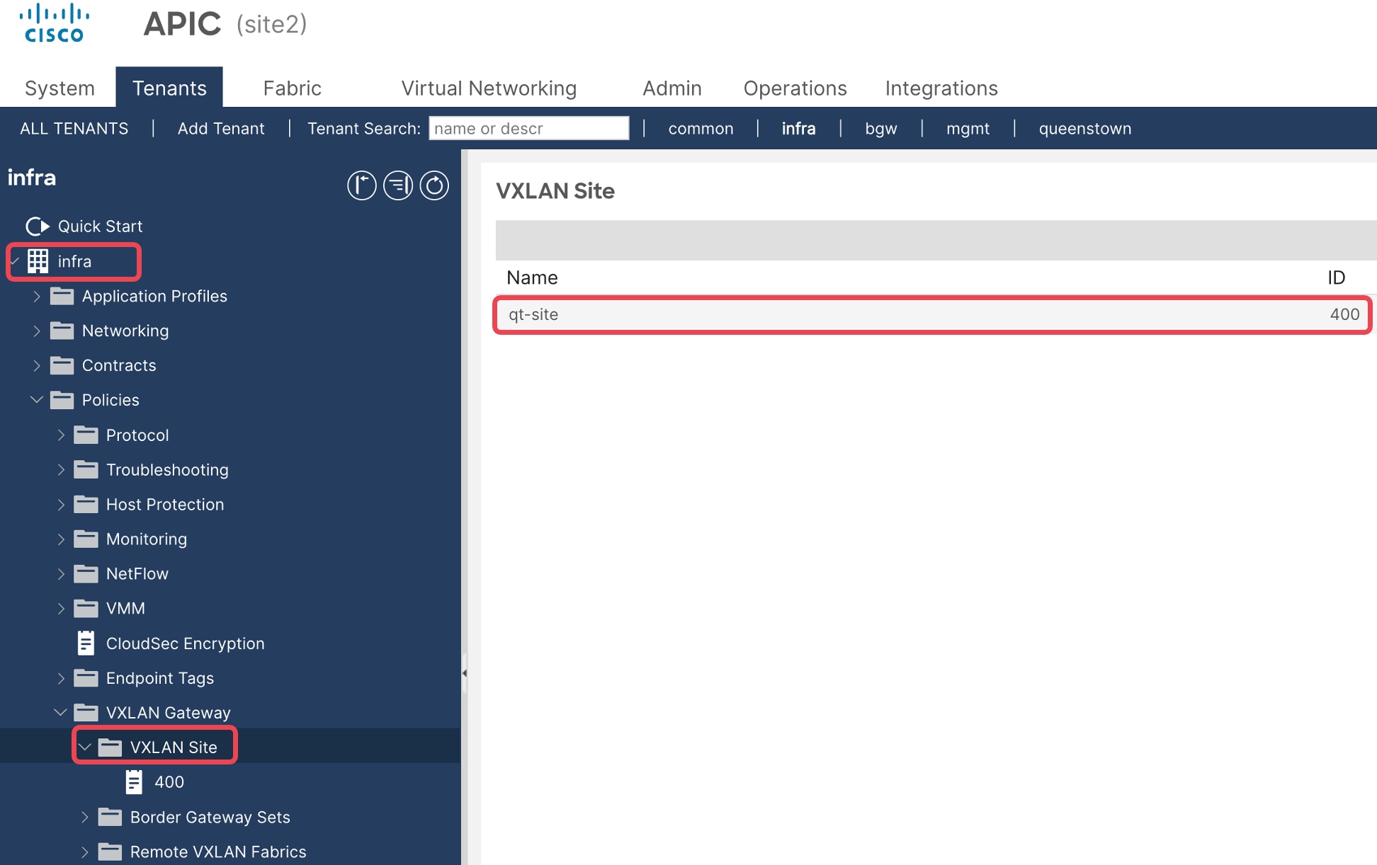
Figure 36. ACI Site 2 VXLAN Site
ACI Site 2 - Remote VXLAN Sites
Because the remote VXLAN site (ACI Site 1) consists of three Border Gateways: two in Pod 1 and one in Pod 2, we must configure three corresponding EVPN peers. These are defined using the loopback IP addresses of the ACI Site 1 Border Gateways: 1.1.1.101, 1.1.1.102, and 2.2.2.202.
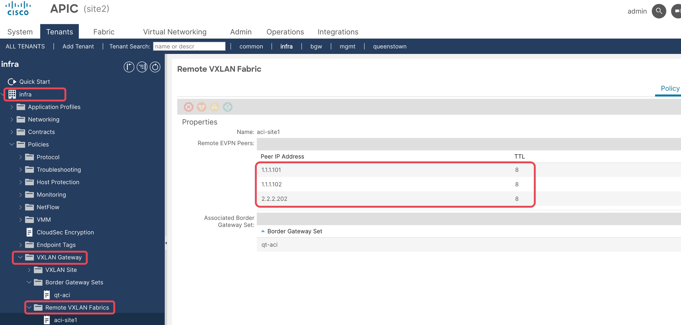
Figure 37. ACI Site 2 Remote VXLAN Fabrics
This section covers verification of the underlay and overlay configurations by validating routing and control plane reachability. For reference, the topology with IP addressing is shown again below:
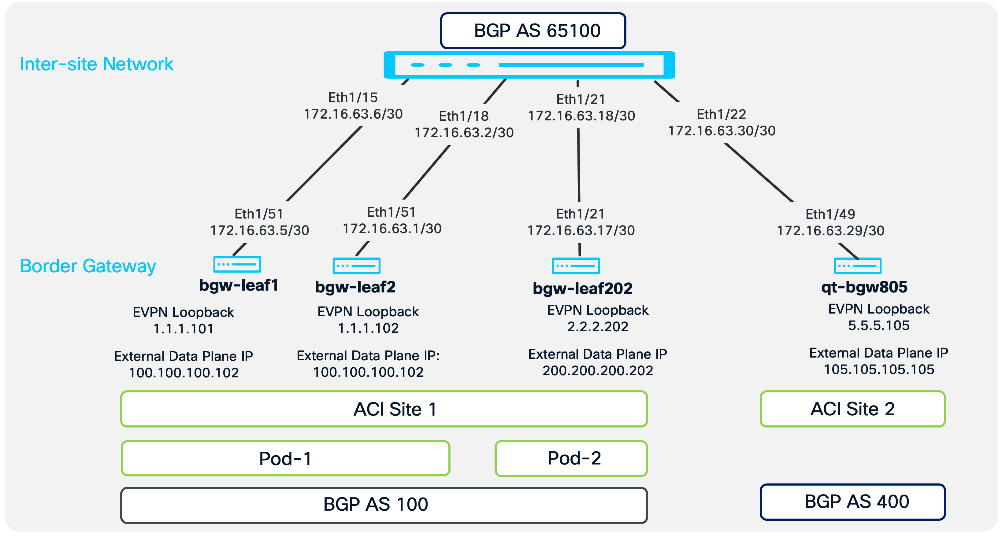
Figure 38. Topology with IP addressing
While CLI commands are available for detailed troubleshooting, the APIC GUI offers built-in features that simplify the process of monitoring BGP EVPN adjacency status.
The following figures show the successful configuration, where the first Border Gateway in ACI Site 1 has established five EVPN adjacencies.
● 1.1.1.102: The second Border Gateway in Pod 1 of ACI Site 1
◦ This EVPN session is used to exchange EVPN Type-4 routes for Designated Forwarder (DF) election.
● 2.2.2.102: The first Border Gateway in Pod 2 of ACI Site 1
◦ This EVPN session is used to exchange EVPN Type-4 routes for Designated Forwarder (DF) election.
● 5.5.5.105: The Border Gateway in the remote site, ACI Site 2
◦ This EVPN session is used to exchange EVPN Type-2, Type-3, Type-5 routes.
● 10.1.248.0: The first spine in Pod 1 of ACI Site 1
◦ This EVPN session is used to exchange EVPN Type-2 between Border Gateway and Spine.
● 10.1.248.1: The second spine in Pod 1 of ACI Site 1
◦ This EVPN session is used to exchange EVPN Type-2 between Border Gateway and Spine.
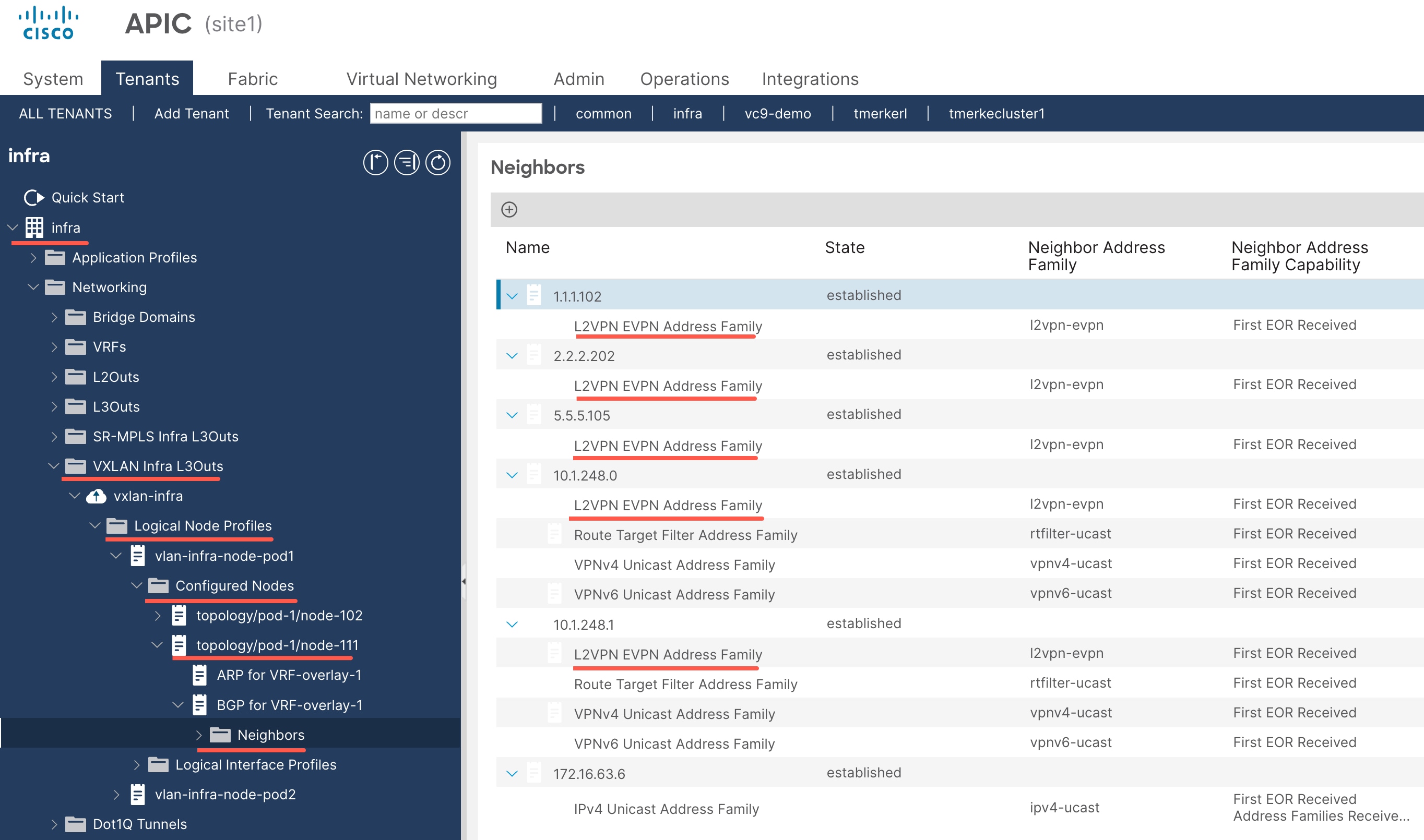
Figure 39. ACI Site 1 Border Gateway bgw-leaf1 BGP EVPN neighbors
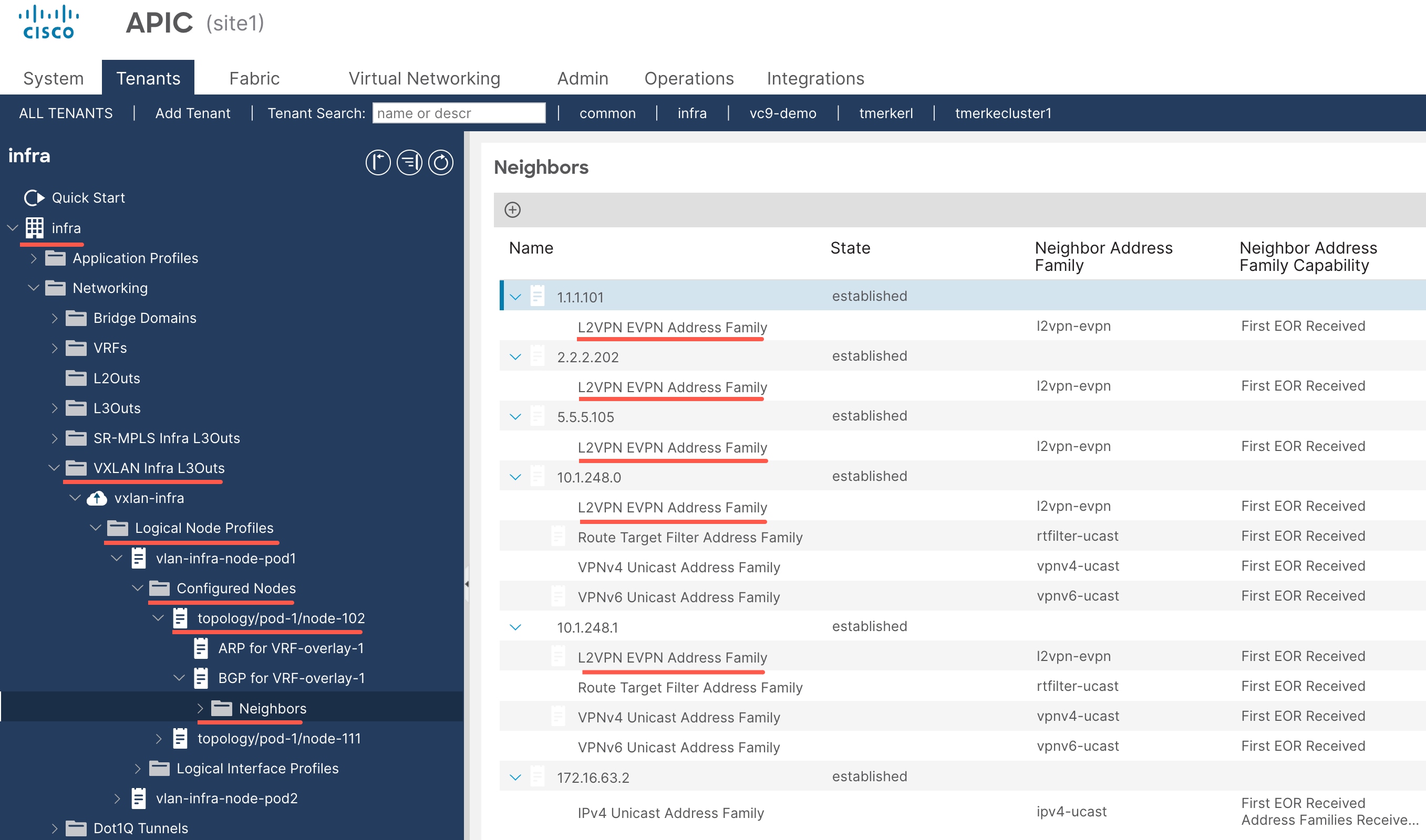
Figure 40. ACI Site 1 Border Gateway bgw-leaf2 BGP EVPN neighbors
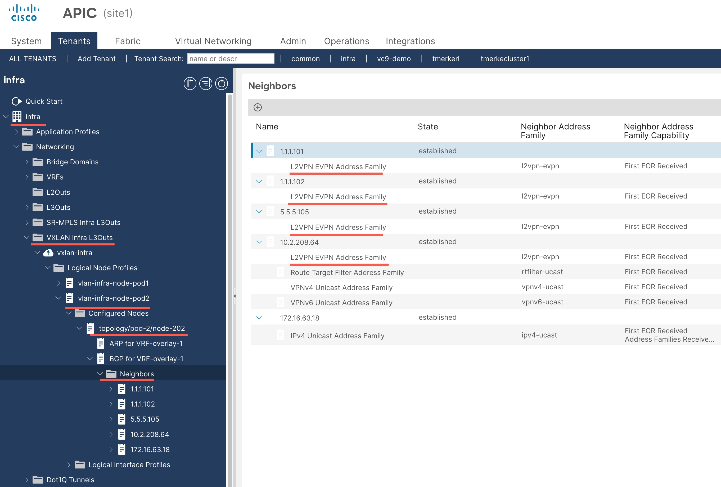
Figure 41. ACI Site 1 Border Gateway bgw-leaf202 BGP EVPN neighbors
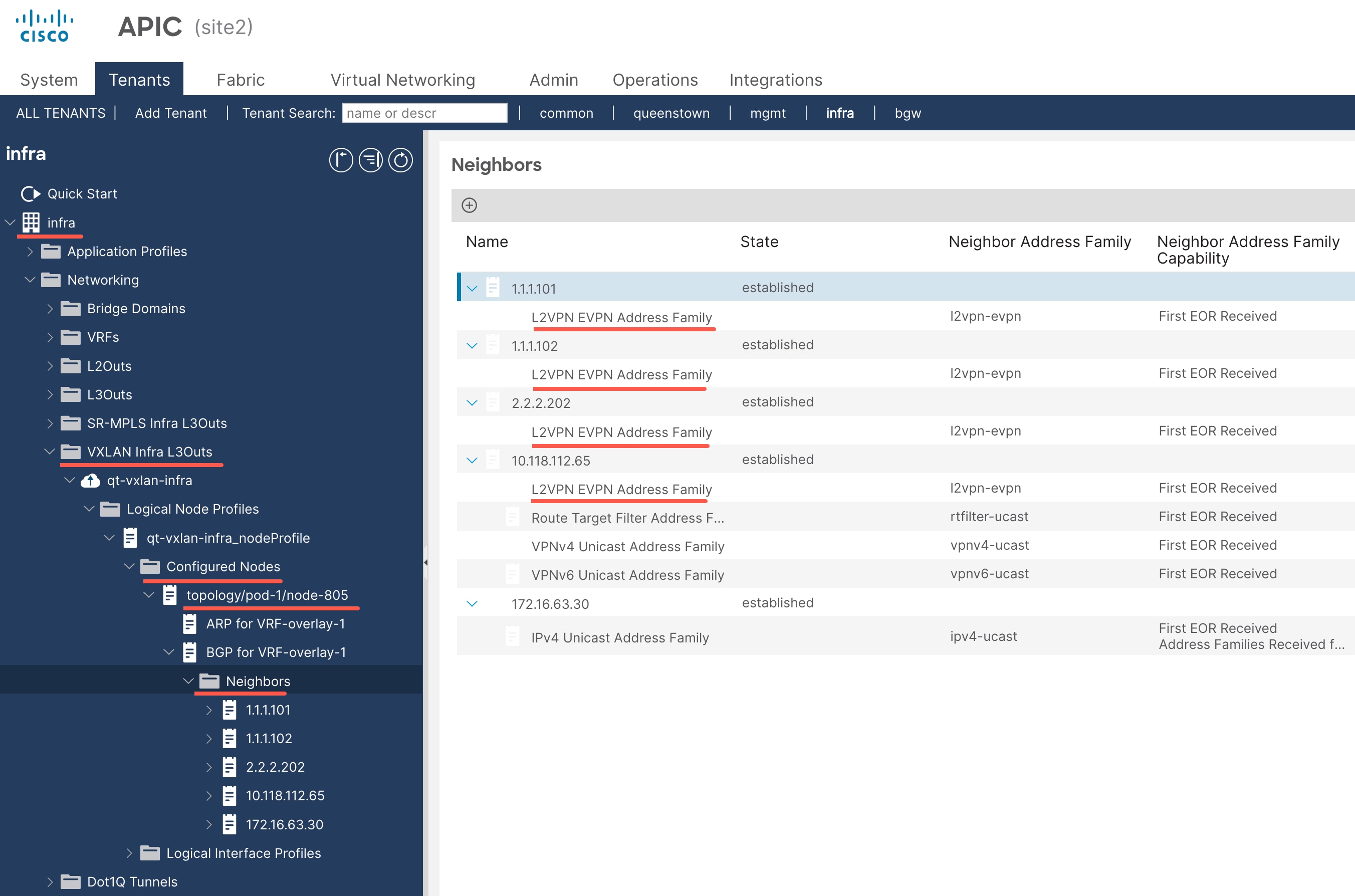
Figure 42. ACI Site 2 Border Gateway qt-bgw805 BGP EVPN neighbors
With the Border Gateway Route Server (or “Route Server” for short), BGP EVPN sessions are established between ACI Border Gateways and the Route Servers, eliminating the need for direct inter-site BGP EVPN peering. These sessions are built between the loopback interfaces of the ACI Border Gateways and the Route Server. Loopback reachability is carried via BGP IPv4, while the Inter-Site Network (ISN) continues to handle underlay BGP functions exclusively.
● A Route Server is a dedicated node that acts as a centralized EVPN BGP route reflector like entity between fabrics using eBGP.
● Deployment model: Supported as dedicated standalone nodes; also supports co-location where the same physical node serves as both the Route Server and the ISN (Inter-Site Network) forwarding node.
● Protocol: All sessions between BGWs and Route Servers are eBGP sessions.
● Redundancy: On production it is recommended to deploy more than one Route Server for redundancy; no BGP overlay session is required between the Route Servers themselves.
● AS Flexibility: The Route Server cluster can reside within a single AS or be spread across multiple ASes.
Although the Route Server and ISN functions can reside on the same device, this deployment example utilizes a dedicated Nexus 9000 NX-OS for the Route Server. For production environments, deploying Route Servers in a redundant pair is recommended to ensure high availability.
The architecture consists of three primary session types:
● BGP IPv4 sessions between the ACI Border Gateways (in each Pod/Site) and the ISN.
● BGP IPv4 sessions between the Route Server and the ISN.
● BGP EVPN sessions between the ACI Border Gateways and the Route Server.
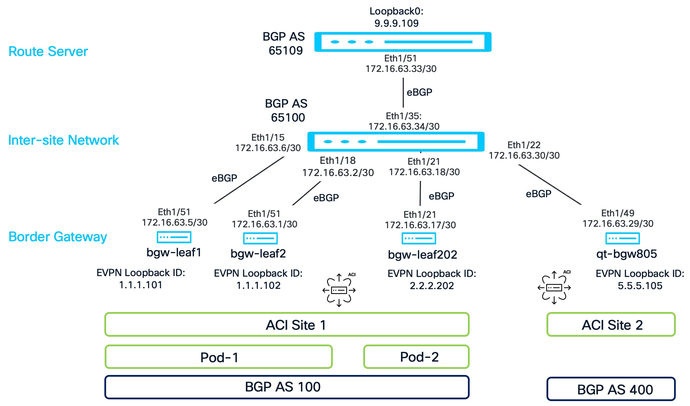
Figure 43. Infra VXLAN L3Out Route Server option
From a configuration perspective, the underlay VXLAN infrastructure remains unchanged across both ACI sites. The only modification is to the overlay BGP EVPN sessions. Instead of defining the peer ACI site as a remote site, both Site 1 and Site 2 now point to the Route Server as the remote site.
● Configure external underlay BGP sessions between the ISN and the ACI Border Gateways.
● Configure external underlay BGP sessions between the ISN and the Route Server.
● On the Route Server, advertise the Loopback0 interface into BGP.
● On the Route Server, configure BGP EVPN peering with the ACI Border Gateways.
● On both ACI sites, configure the Route Server as a Remote VXLAN Fabric.
● (Optional) Remove any existing legacy remote VXLAN fabric configurations if transitioning from a non-Route Server environment. Create Route Server as Remote VXLAN fabric.
# Create a VRF
vrf context bgw
address-family ipv4 unicast
# Interface configuration
interface Ethernet1/15
description --> bgw-leaf1 51
mtu 9216
vrf member bgw
ip address 172.16.63.6/30
no shutdown
interface Ethernet1/18
description --> bgw-leaf2 e1/52
mtu 9216
vrf member bgw
ip address 172.16.63.2/30
no shutdown
interface Ethernet1/21
description bgw-leaf202 e1/21
mtu 9216
vrf member bgw
ip address 172.16.63.18/30
no shutdown
interface Ethernet1/22
description --> qt-bgw-805
mtu 9216
vrf member bgw
ip address 172.16.63.30/30
no shutdown
interface Ethernet1/35
description --> Route-Server
mtu 9216
vrf member bgw
ip address 172.16.63.34/30
no shutdown
# BGP configuration
router bgp 65100
vrf bgw
neighbor 172.16.63.1
remote-as 100
update-source Ethernet1/18
address-family ipv4 unicast
disable-peer-as-check
neighbor 172.16.63.5
remote-as 100
update-source Ethernet1/15
address-family ipv4 unicast
disable-peer-as-check
neighbor 172.16.63.17
remote-as 100
update-source Ethernet1/21
address-family ipv4 unicast
disable-peer-as-check
neighbor 172.16.63.29
remote-as 400
update-source Ethernet1/22
address-family ipv4 unicast
neighbor 172.16.63.33
remote-as 65109
update-source Ethernet1/35
address-family ipv4 unicast
# Interface configuration
interface loopback0
ip address 9.9.9.109/32 tag 54321
interface Ethernet1/51
description --> ISN
no switchport
ip address 172.16.63.33/30 tag 54321
no shutdown
# Route-map configuration
route-map rmap-redist-direct permit 10
match tag 54321
route-map unchanged permit 10
set ip next-hop unchanged
# BGP IPv4 Unicast and BGP EVPN configuration
router bgp 65109
address-family ipv4 unicast
network 9.9.9.109/32
address-family l2vpn evpn
retain route-target all
template peer OVERLAY-PEERING
update-source loopback0
ebgp-multihop 5
address-family l2vpn evpn
send-community
send-community extended
route-map unchanged out
neighbor 1.1.1.101
inherit peer OVERLAY-PEERING
remote-as 100
description multi-site overlay session to ACI Site 1 BGW bgw-leaf1
address-family l2vpn evpn
rewrite-evpn-rt-asn
neighbor 1.1.1.102
inherit peer OVERLAY-PEERING
remote-as 100
description multi-site overlay session to ACI Site 1 BGW bgw-leaf2
address-family l2vpn evpn
rewrite-evpn-rt-asn
neighbor 2.2.2.202
inherit peer OVERLAY-PEERING
remote-as 100
description multi-site overlay session to ACI Site 1 BGW bgw-leaf202
address-family l2vpn evpn
rewrite-evpn-rt-asn
neighbor 5.5.5.105
inherit peer OVERLAY-PEERING
remote-as 400
description multi-site overlay session to ACI Site 2 BGW qt-leaf805
address-family l2vpn evpn
rewrite-evpn-rt-asn
neighbor 172.16.63.34
remote-as 65100
description BGP session to ISN
update-source Ethernet1/51
address-family ipv4 unicast
Since both ACI Sites are using RT in the same format ASN:VNI, and Border Gateway and Route Server are in different ASNs, it is critical to include the “rewrite-evpn-rt-asn” command (supported in Nexus 9000 platform) in your Route Server configuration. This command ensures the Route Server modifies the EVPN Route Target (RT) and Autonomous System Number (ASN) before forwarding updates to BGP EVPN peers. For example, if the ACI Site 1 Border Gateway sends an update with RT 100:30004, the Route Server rewrites it to 65109:30004 before advertising it to Site 2. Without this rewrite, the Site 2 Border Gateway would reject the update because it does not maintain a direct BGP EVPN session with Site 1 and therefore cannot process the original RT. If the Route Server is deployed different platform than Nexus 9000 then the manual rewrite must be utilized.
Unlike the default eBGP behavior, the Route Server must not rewrite the next hop to itself. Instead, it must preserve the original next hop, which is the external anycast address of the originating Border Gateway. Accordingly, a route map must be configured under “address-family l2vpn evpn” to ensure that the next-hop attribute is preserved.
Peer ACI Border Gateway with Route Server
The underlay infrastructure, specifically the VXLAN Infra L3Out connectivity between the ACI Border Gateway and the ISN device, remains unchanged. Ensure that these underlay configuration steps are completed before proceeding. This section outlines the integration of the Route Server, enabling the ACI Border Gateway to establish BGP EVPN control-plane peering with the Route Server. When using the Route Server model, from the perspective of an ACI site, the Route Server functions as the remote VXLAN fabric, since the ACI Border Gateways do not establish direct peering with the remote fabric but instead peer with the Route Server.
Navigate to Infra tenant, Policies, VXLAN Gateway, right click on Remote VXLAN Fabrics and click Create Remote VXLAN Fabric.
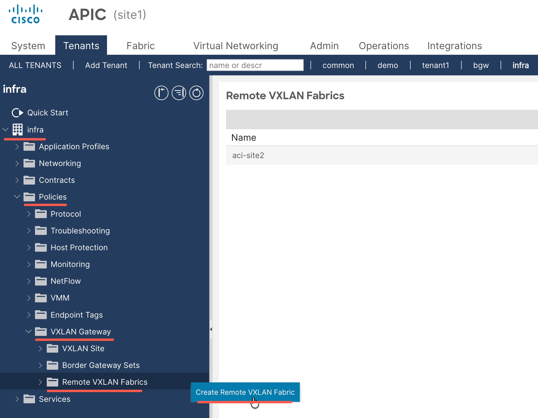
Figure 44. ACI Site 1 Create Remote VXLAN Fabric
Configure a name for the Remote VXLAN fabric. Since it is a route server, this example uses “Route-Server” as the name. Then, click “+” to add the route server information such as the IP address and AS number.
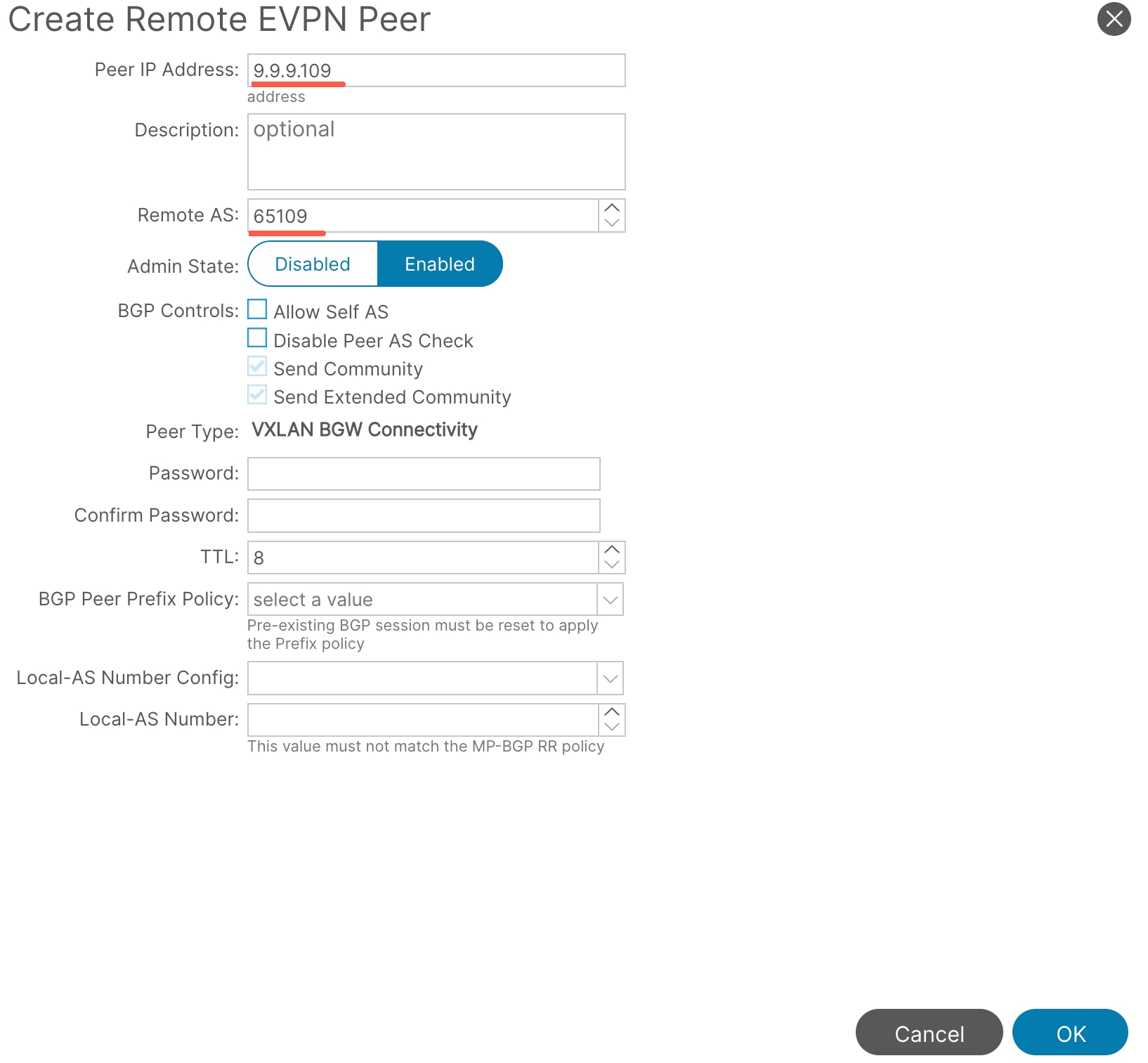
Figure 45. Create a Remote EVPN Peer using the Route Server IP address and ASN
Click OK to proceed. The next step is to associate the Route Server with the Border Gateway Sets. In the Associated Border Gateway Set, click “+” to add Border Gateway Sets.
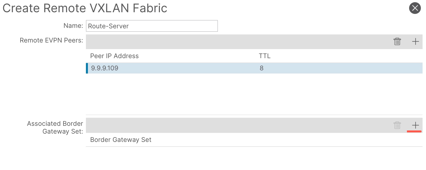
Figure 46. ACI Site 1 Associate Route Server to a Border Gateway Set
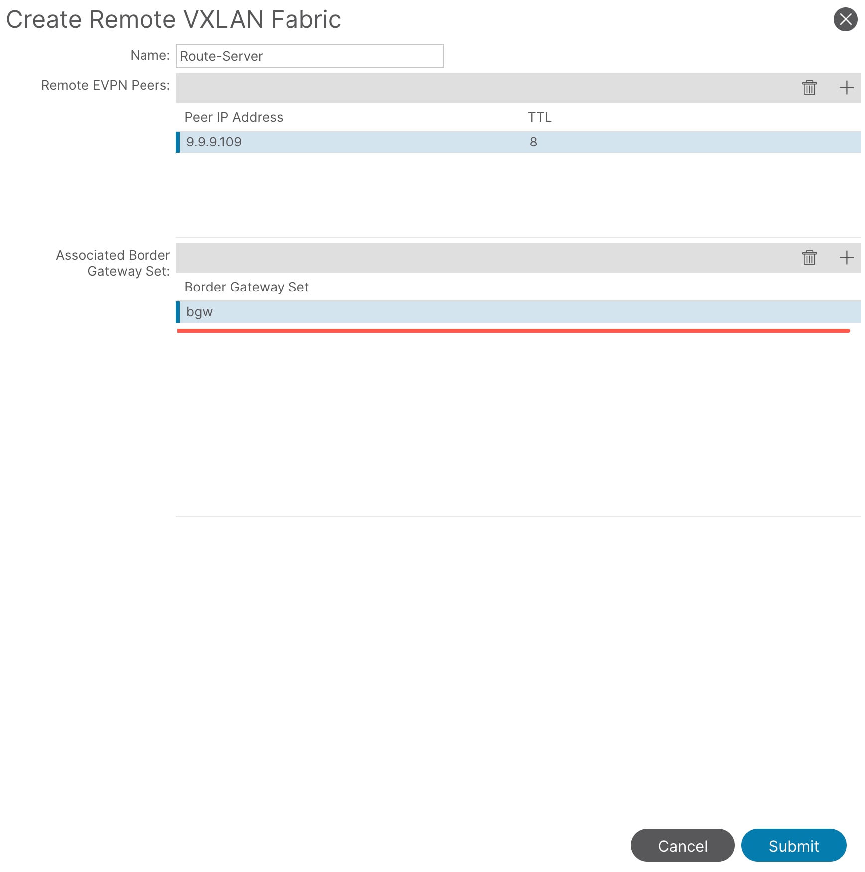
Figure 47. Click Submit to associate the Border Gateway Set
The Route Server now appears as a Remote VXLAN Fabric.
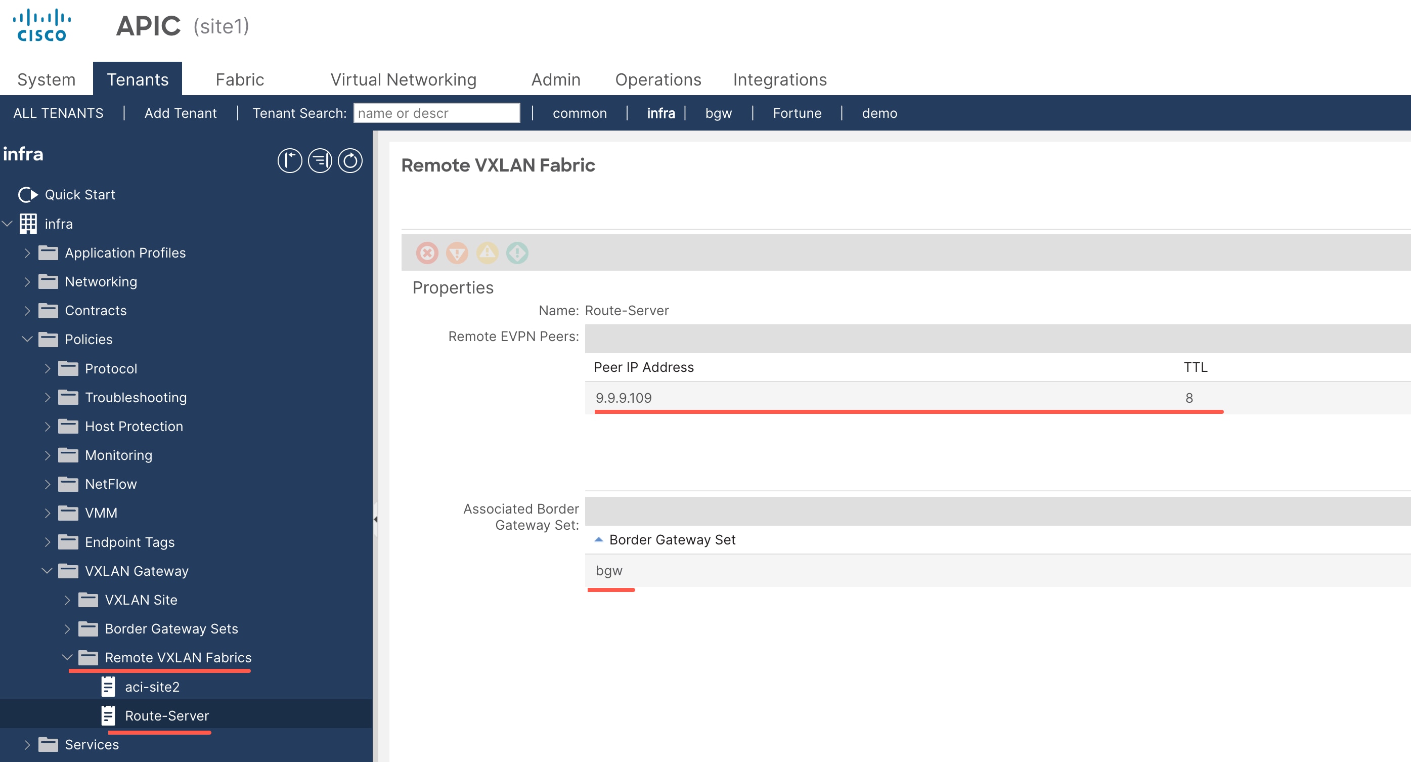
Figure 48. ACI Site 1 Route Server as a remote VXLAN Fabric
If Site 2 was previously configured as a remote site, it can now be removed. In the Remote VXLAN Fabrics window, right-click aci-site2 and select Delete.
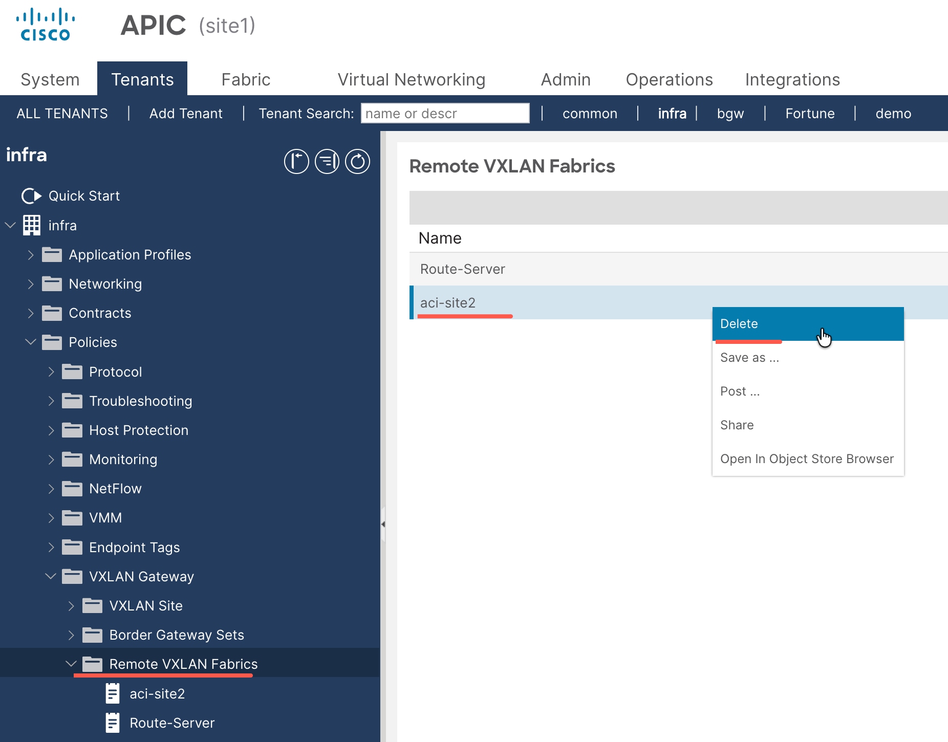
Figure 49. ACI Site 1 Delete the old aci-site2
Repeat the same steps for ACI Site 2. Once the Route Server is added and the old remote site is deleted, the configuration should appear as follows.
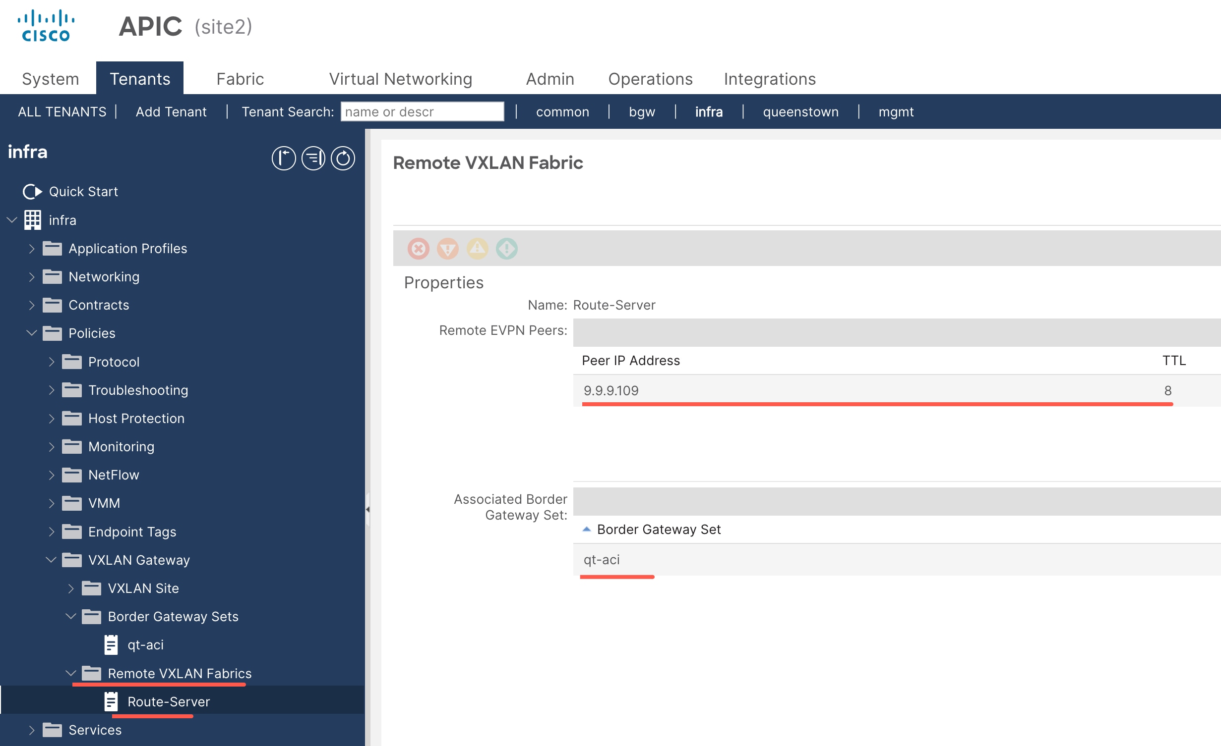
Figure 50. ACI Site 2 Route Server
The verification process is identical to a setup without a Route Server. When a Route Server is deployed, the BGP EVPN control plane is established between each ACI site Border Gateway and the Route Server, eliminating the need for direct BGP EVPN sessions between Border Gateways across different sites.
On the Route Server, the show “bgp l2vpn evpn summary” command displays four established BGP EVPN sessions with the ACI Border Gateways (three from ACI Site 1 and one from ACI Site 2).
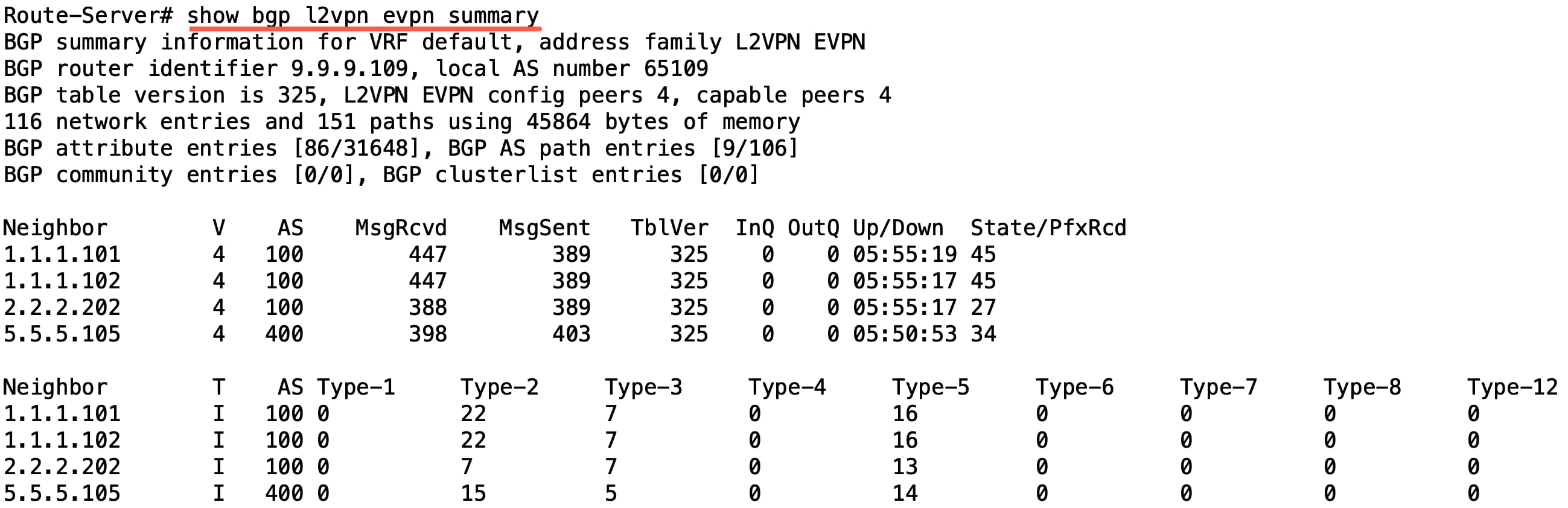
Figure 51. Route server evpn summary
Established BGP EVPN sessions can be verified via the APIC GUI at each site or through the CLI on the respective Border Gateways. Within the APIC GUI, status is available under the Inventory tab or the infra tenant; this section demonstrates verification through the infra tenant. The output below focuses on the first Border Gateway in ACI Site 1, Pod 1. A similar verification procedure can be applied to all other Border Gateways and ACI sites.
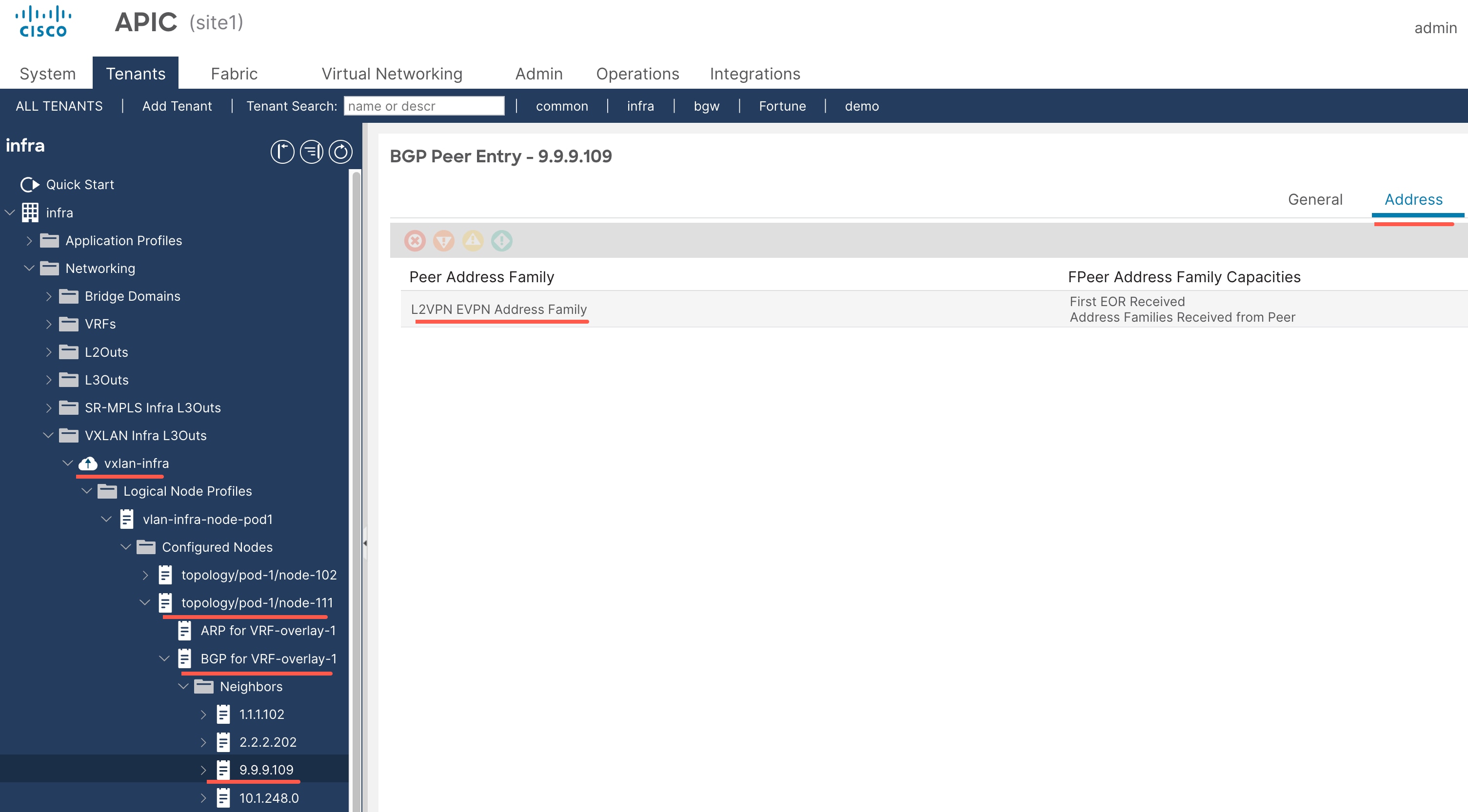
Figure 52. L2VPN EVPN Address Family
Alternatively, checks the status using the command on the Border Gateway in vsh mode.
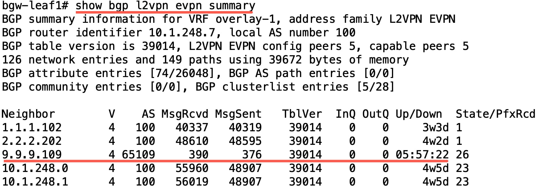
Figure 53. ACI Site 1 - BGP EVPN established session from Border Gateway to Route Server
Please note that after this section, the design will revert to the non-Route Server design. From a high-level architectural perspective, there is no difference in data plane forwarding behavior between the Route Server and Non-Route Server designs, as the Route Server does not participate in the data plane.
Overlay Networking and Use Cases Deployment Details
This section describes the tenant-based baseline configuration and the supported use cases built on top of it. The baseline configuration introduced in the first subsection provides the foundation for most of the scenarios covered later in this document. It is recommended to review that subsection first, as it defines the common building blocks used throughout this section, including stretched VRFs, stretched Bridge Domains (BDs), and Endpoint Security Groups (ESGs) configuration with normalized pcTags.
The following use cases are covered in this section.
● Use Case 1: Intra-Subnet Communication
Endpoints are in the same IP subnet and the same BD. The endpoints are in the same EPG/ESG, thus communication between them does not require a contract.
● Use Case 2: Inter-Subnet Communication with Stretched BDs and Multiple ESGs
Endpoints are in different IP subnets and in different stretched BDs. The endpoints are in different ESGs, thus communication between them requires a contract.
● Use Case 3: Inter-Subnet Communication with Non-Stretched BDs and Single ESG
Endpoints are in different IP subnets and in different local (non-stretched) BDs. The endpoints are in the same ESG, thus communication between them does not require a contract.
● Use Case 4: Inter-Subnet Communication with Non-stretched BDs and Multiple ESGs
Endpoints are in different IP subnets and in different non-stretched (local) BDs. The endpoints are in the different ESGs, thus communication between them require a contract.
● Use Case 5: North-South Communication Across ACI Sites with a Stretched BD
Endpoints in a stretched BD communicate with external endpoints through the other site.
● Use Case 6: North-South Communication Across ACI Sites with a Non-stretched BD
Endpoints in a non-stretched (local) BD communicate with external endpoints through the other site.
● Use Case 7: Transit Routing Across ACI Sites
External endpoints communicate with external endpoints through the other site.
● Use Case 8: Design Considerations and Traffic Flow Optimization for Overlapping Prefixes in Multi-L3Out Deployments
The same IP prefix is advertised from multiple L3Outs in different sites. This use case presents design considerations along with inbound and outbound traffic flow optimization.
● Use Case 9: Inter-VRF Communication (Shared Services) with Stretched BDs
Communication between endpoints located in different stretched BD in different stretched VRFs.
● Use Case 10: Inter-VRF Communication (Shared Services) with Non-stretched BDs
Communication between endpoints located in different non-stretched BD in different stretched VRFs.
● Use Case 11: Inter-VRF Communication (Shared Services) with Shared L3Out
Endpoint in a VRF communicates with an external endpoint in a different VRF through the other site.
● Use Case 12: Service Node Integration
Explains inter-site traffic flow with L4-L7 service nodes insertion. The service insertion is performed independently within each site.
User Tenant Baseline Configuration
Completion of this baseline is a prerequisite before proceeding to the specific use cases. Additionally, it is assumed that all necessary access policies and domains have already been configured accordingly.
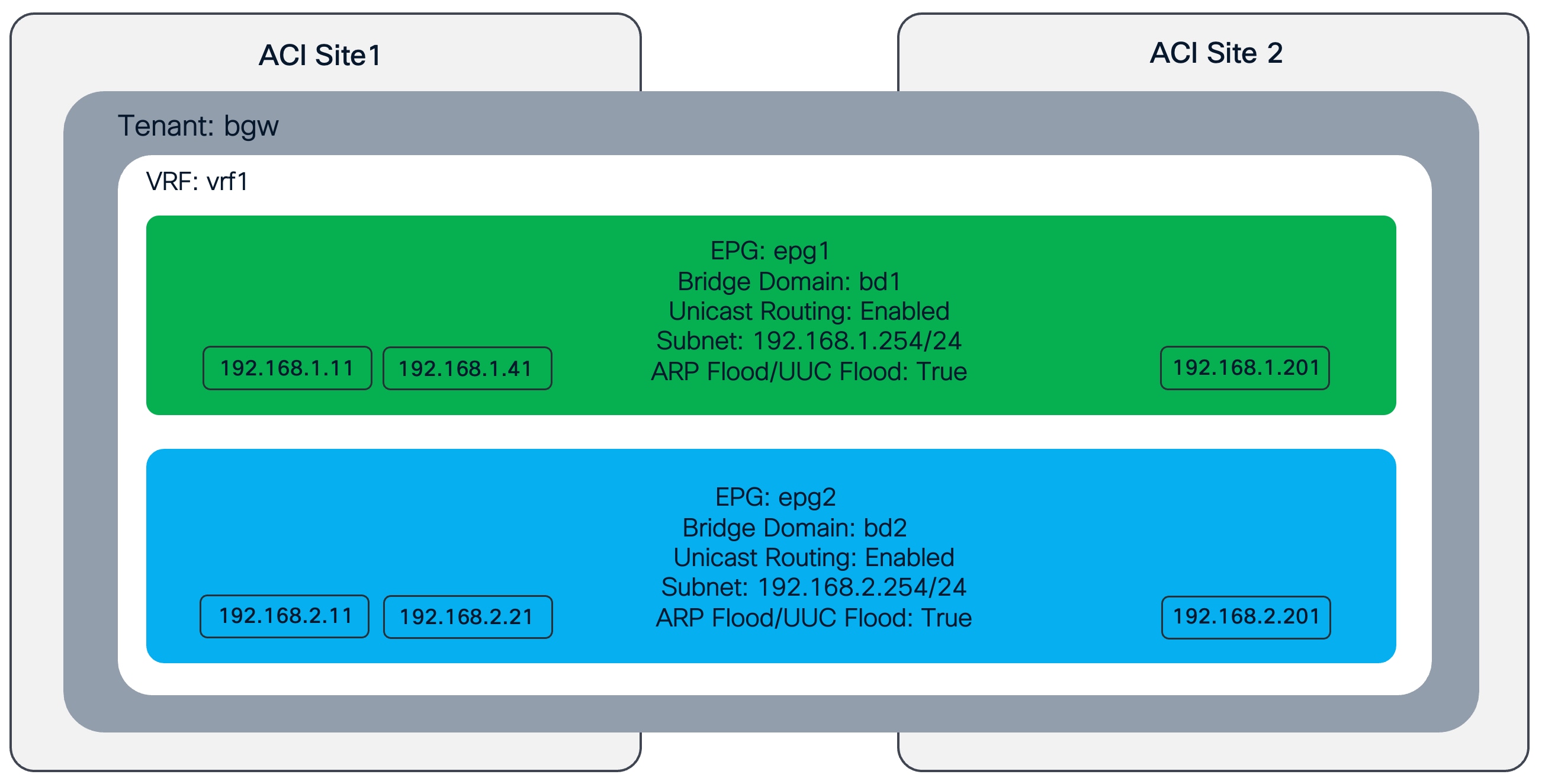
Figure 54. User Tenant Baseline Configuration
Baseline configuration is the following:
● Tenant: bgw
● VRF: vrf1
● Bridge Domain: bd1, bd2 (Unknown Unicast Flooding ON)
● Application Profile ap1 (Note: Not depicted in the diagram)
● Endpoint Group: epg1, epg2
Note: As of APIC release 6.2(2), “Unknown Unicast Flooding” must be ON for the stretched BDs and it is enforced by APIC.
The EPGs are associated with the appropriate domains; for this example, a VMM domain is utilized. EPGs are later migrated to ESGs. The following endpoints are available for connectivity testing:
● ESG esg1 endpoints:
◦ 192.168.1.11: endpoint in Pod 1 ACI Site 1
◦ 192.168.1.41: endpoint in Pod 2 ACI Site 1
◦ 192.168.1.201: endpoint in ACI Site 2
● ESG esg2 endpoints:
◦ 192.168.2.11: endpoint in Pod 1 ACI Site 1
◦ 192.168.2.21: endpoint in Pod 2 ACI Site 1
◦ 192.168.2.201: endpoint in ACI Site 2
The VRF and BDs are stretched across both ACI sites by associating them with the Border Gateway on each site. This ensures that the network objects are correctly deployed to the Border Gateways of both sites. The screenshots below show the baseline configuration for EPGs and the stretched VRF/BD constructs applied across the sites.
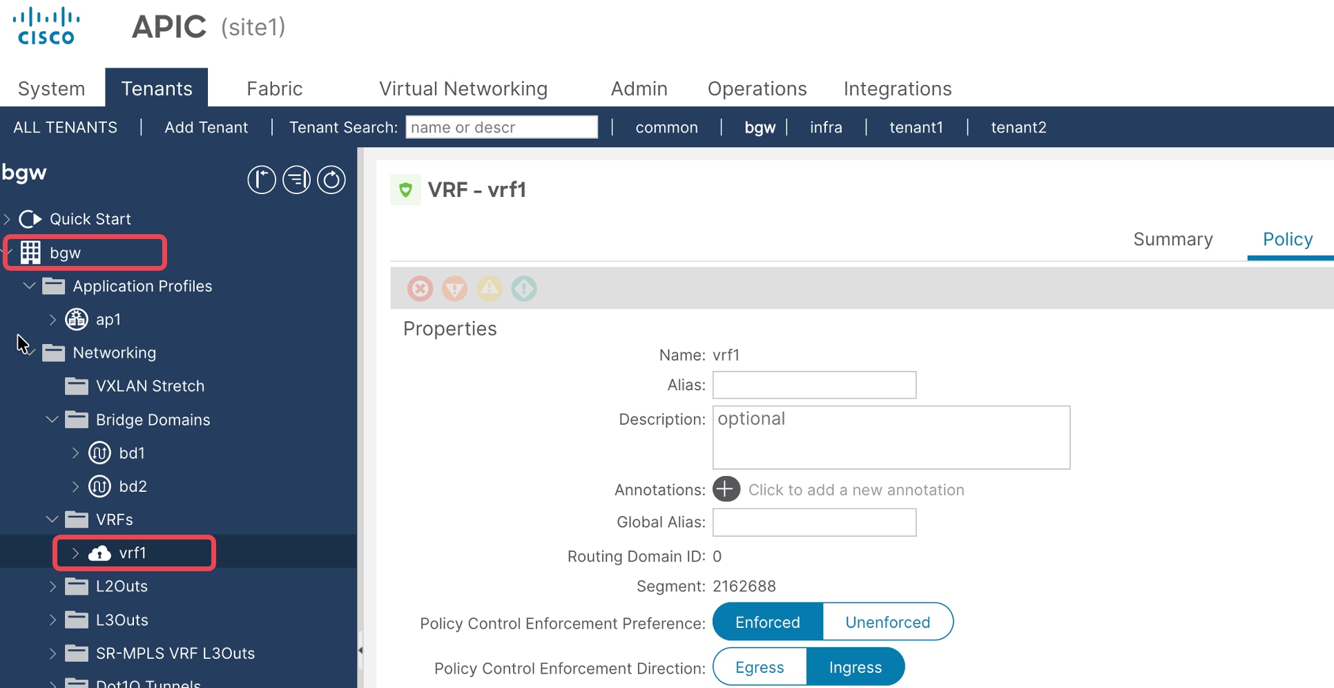
Figure 55. ACI Site 1 tenant and vrf1
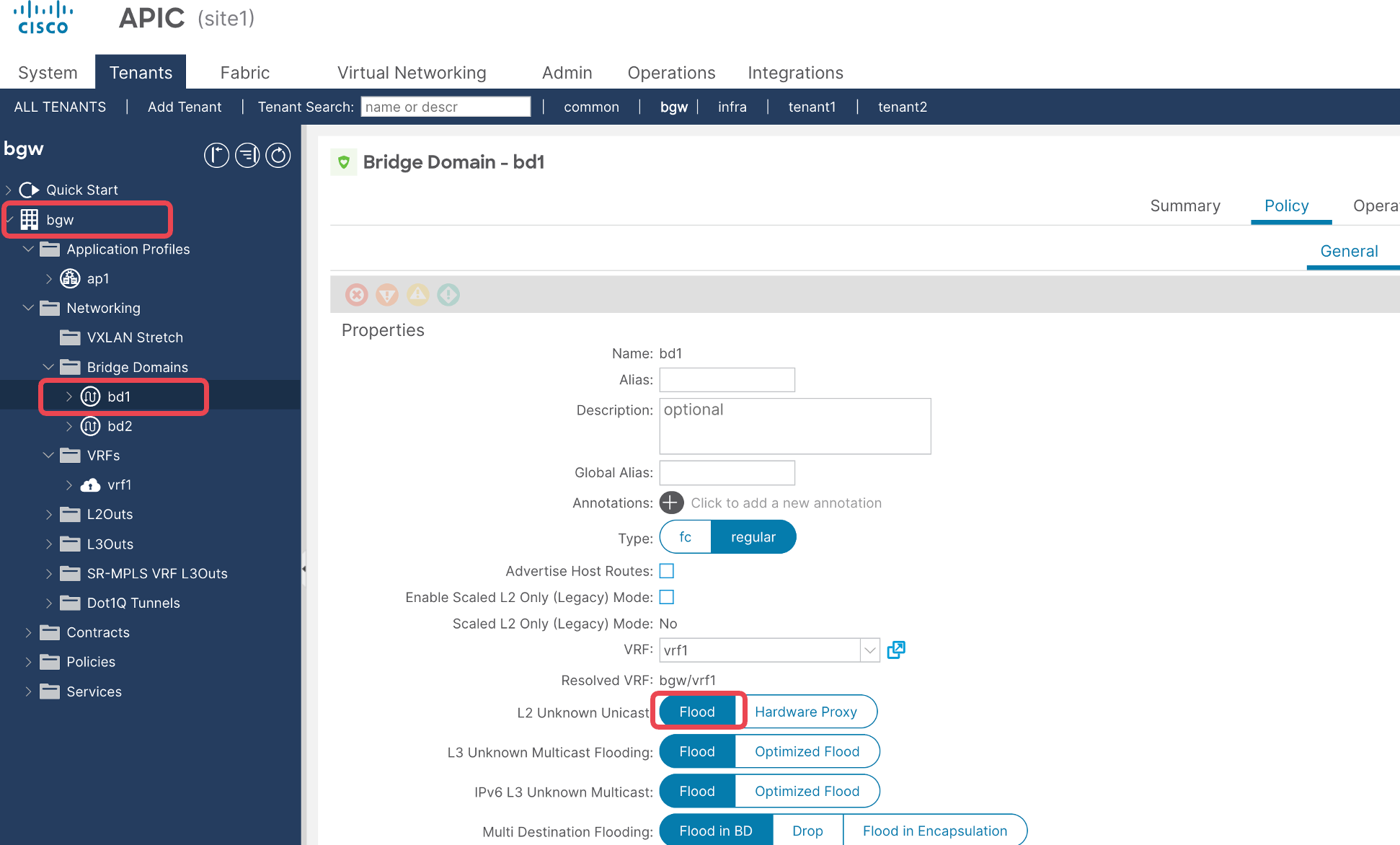
Figure 56. ACI Site 1 bd1
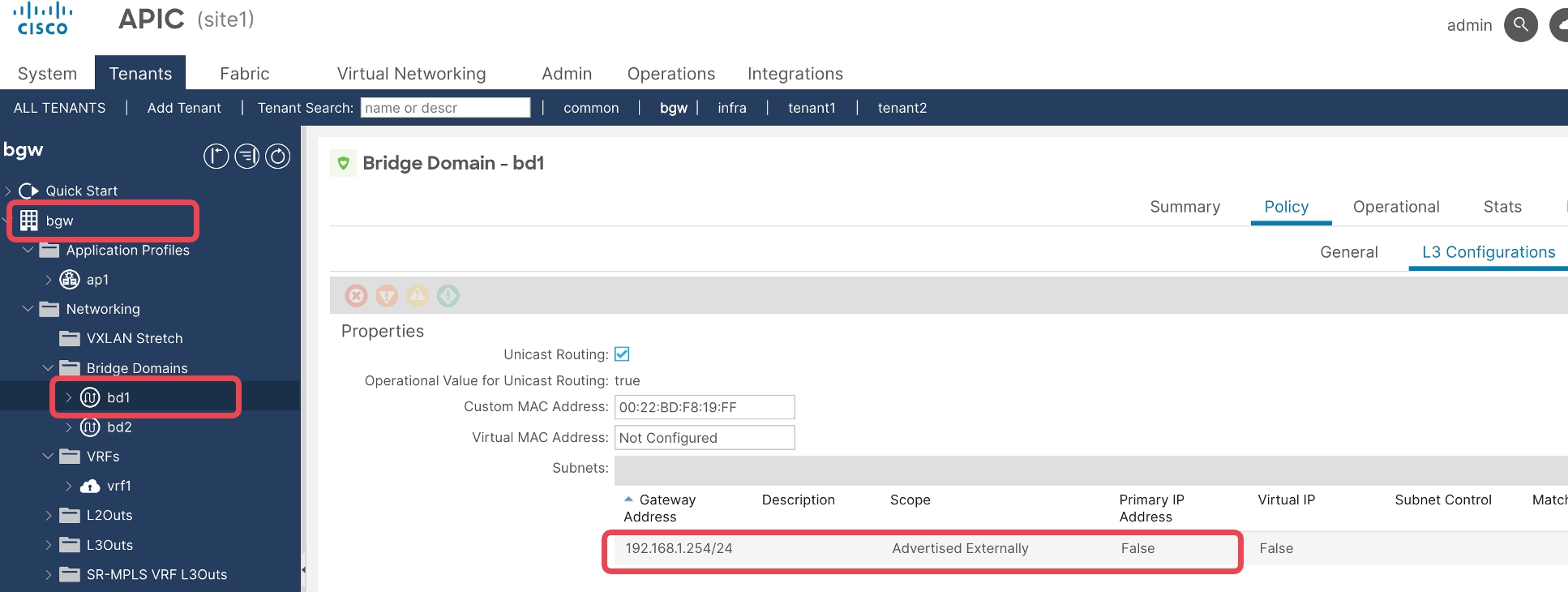
Figure 57. ACI Site 1 bd1 subnet
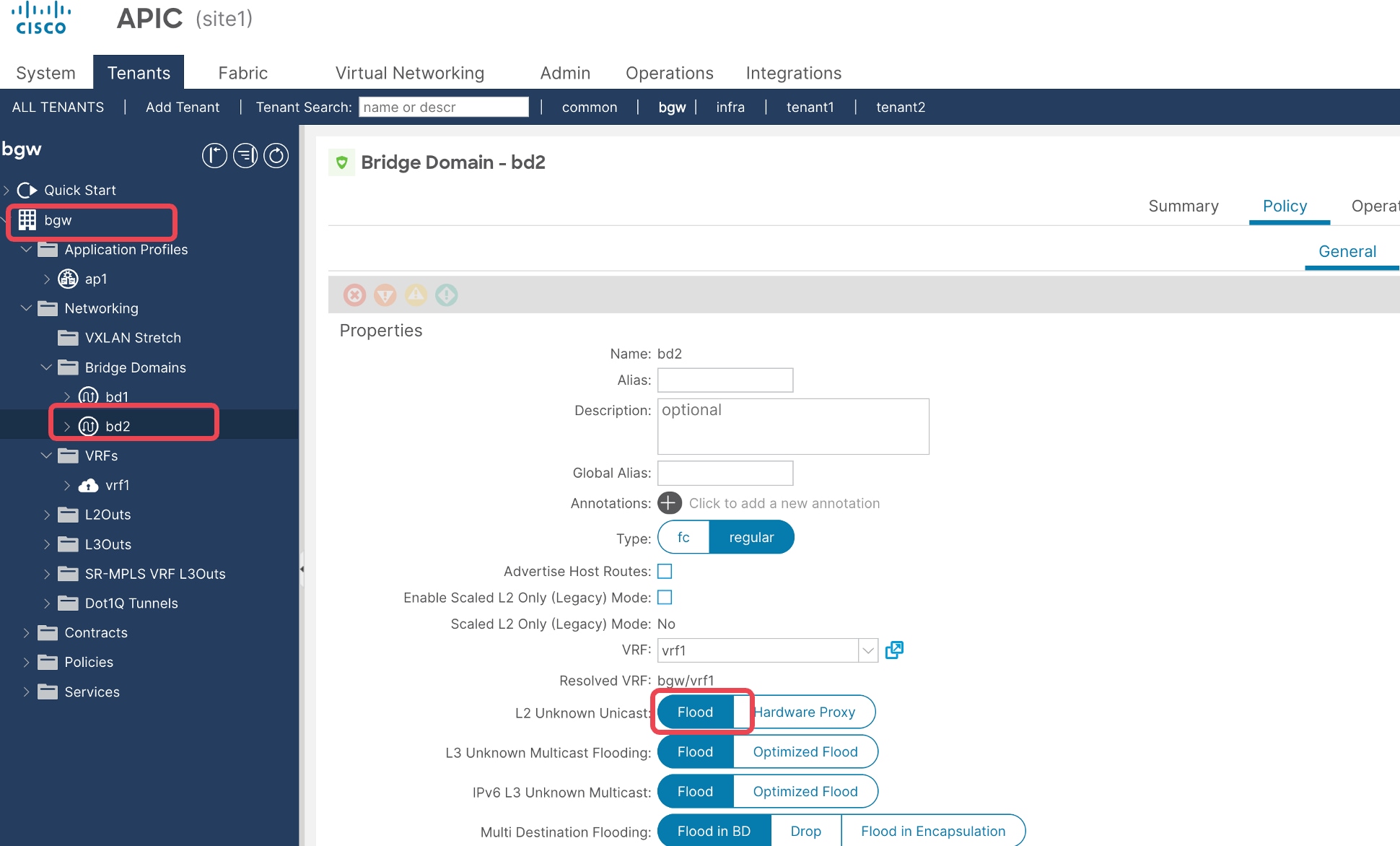
Figure 58. ACI Site 1 bd2
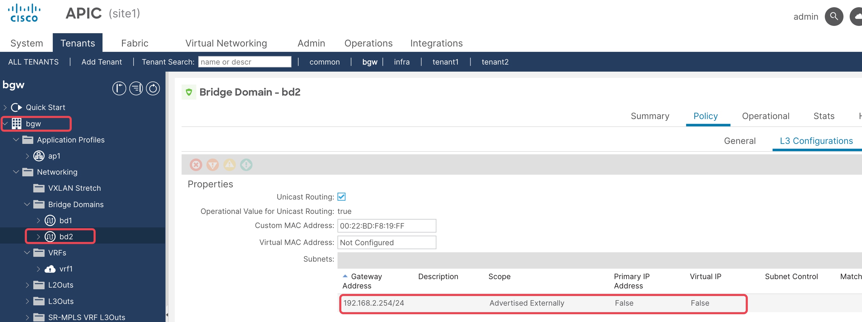
Figure 59. ACI Site 1 bd2 subnet
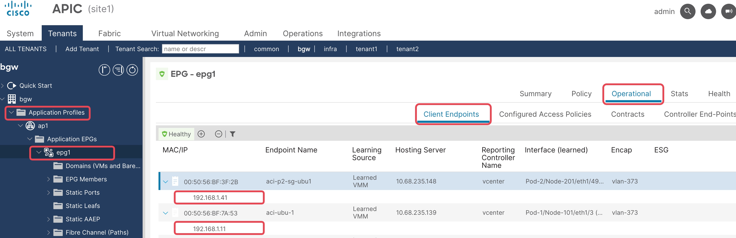
Figure 60. ACI Site 1 epg1 endpoints
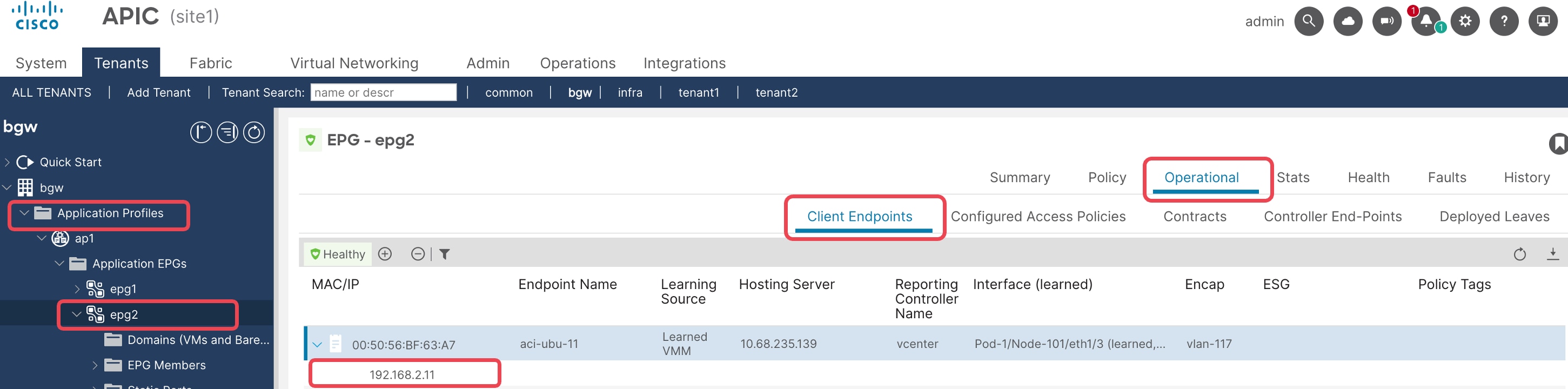
Figure 61. ACI Site 1 epg2 endpoints
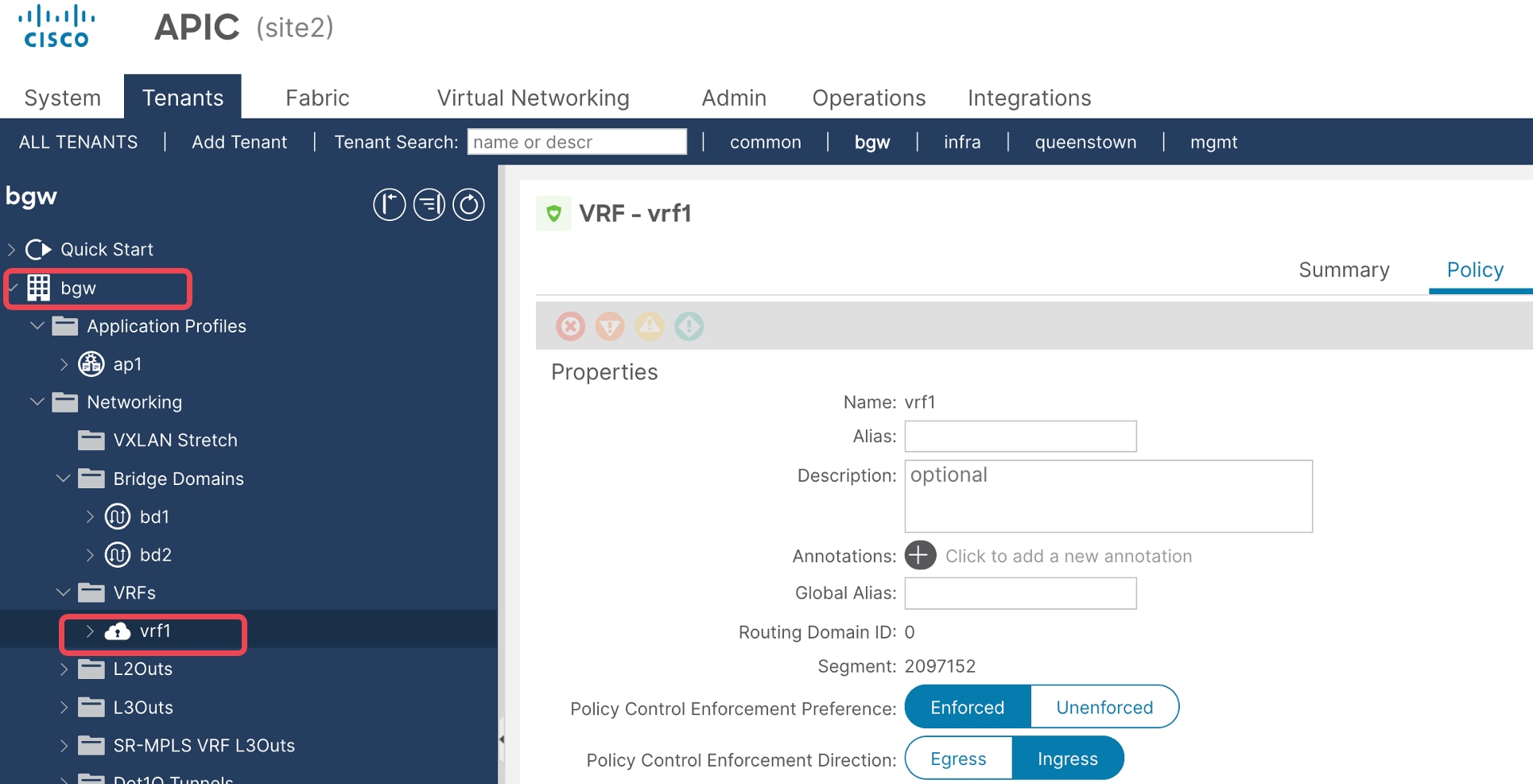
Figure 62. ACI Site 2 tenant and vrf1
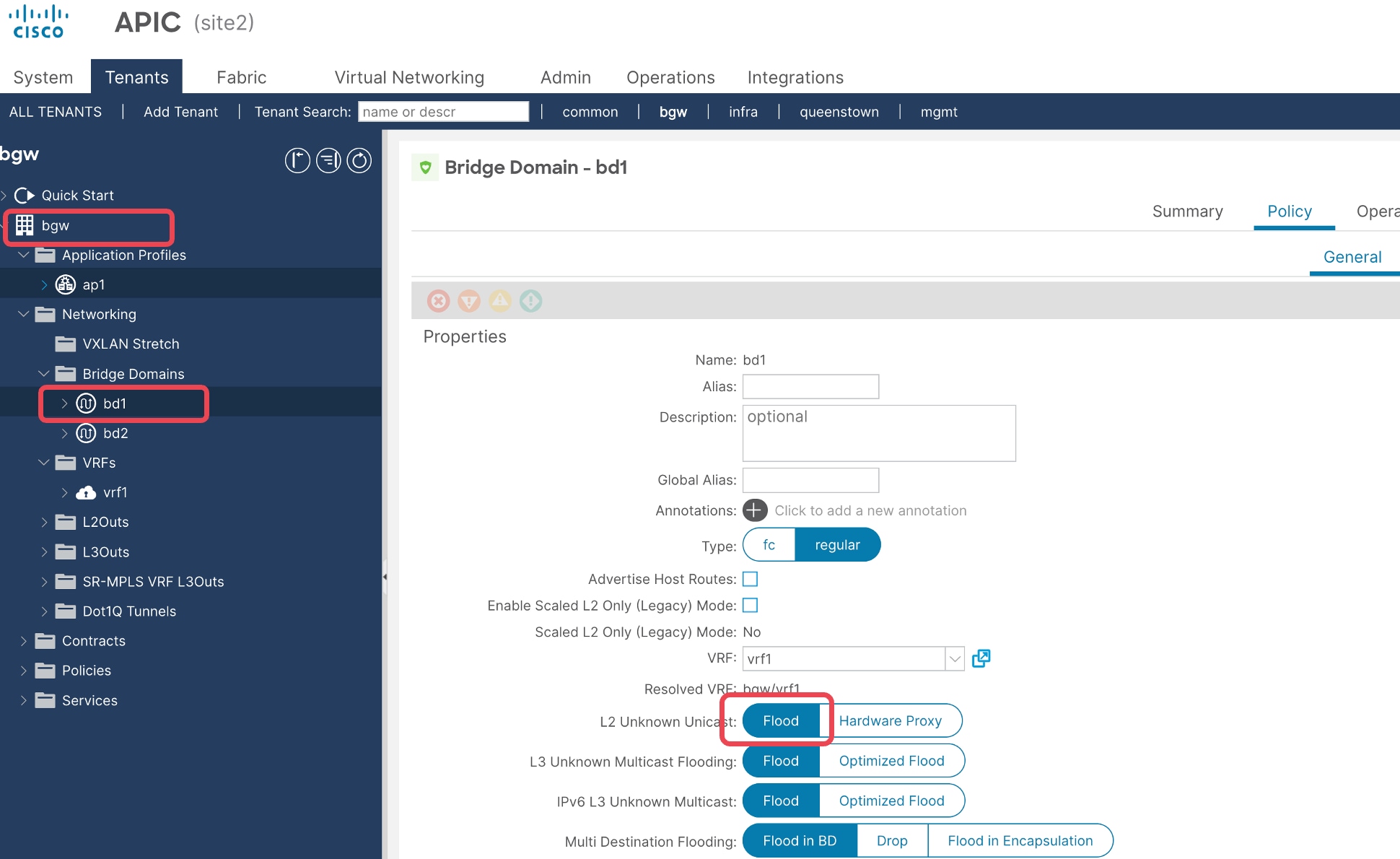
Figure 63. ACI Site 2 bd1
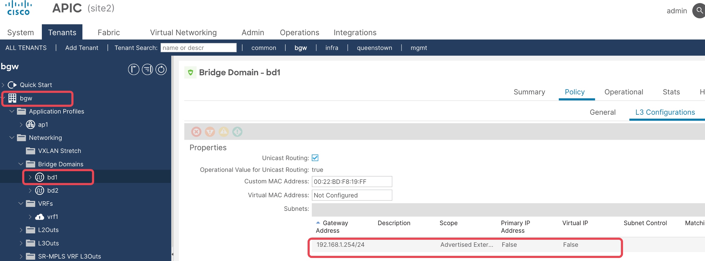
Figure 64. ACI Site 2 bd1 subnet
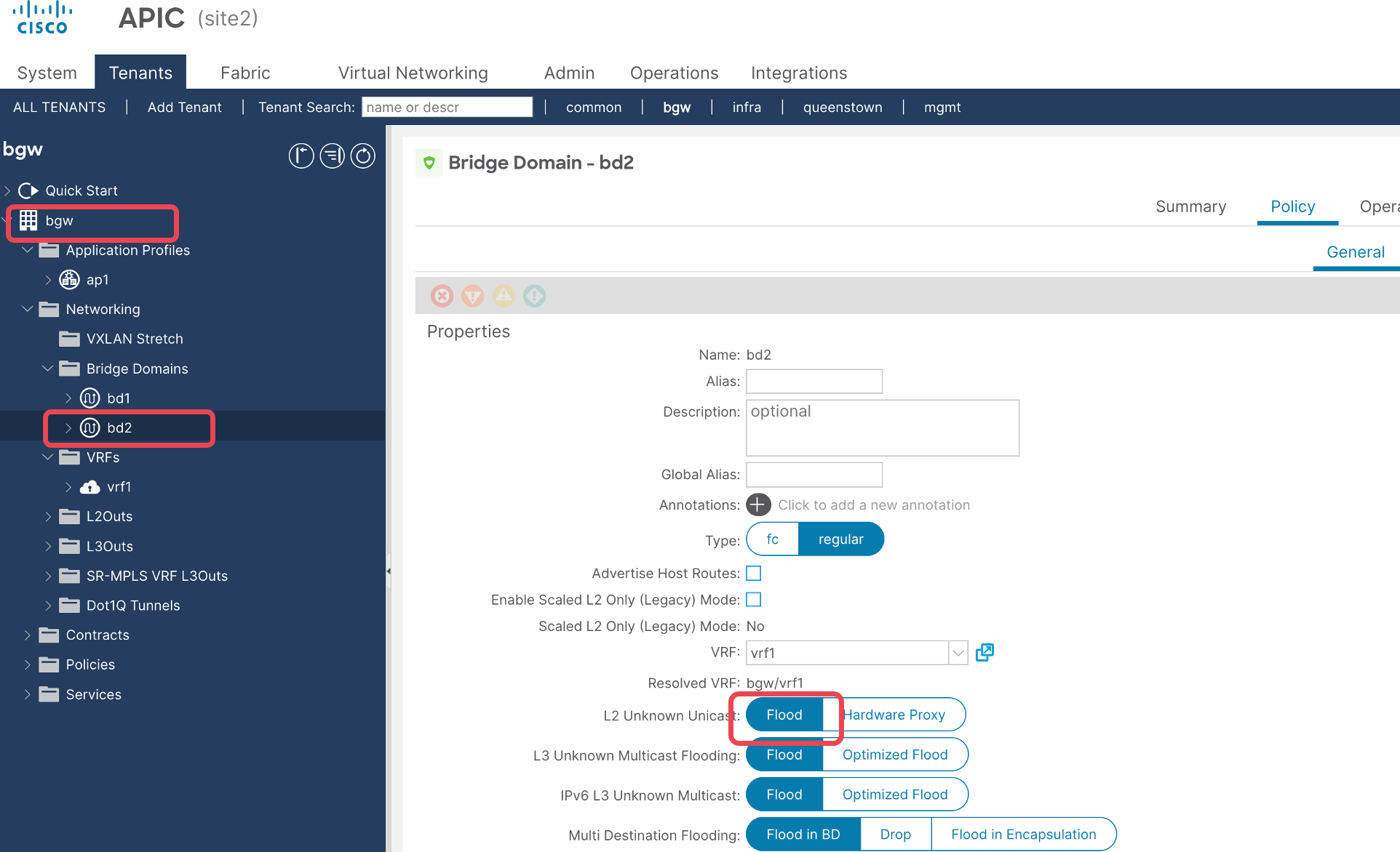
Figure 65. ACI Site 2 bd2
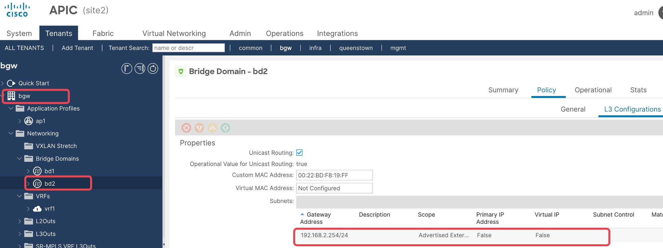
Figure 66. ACI Site 2 bd2 subnet
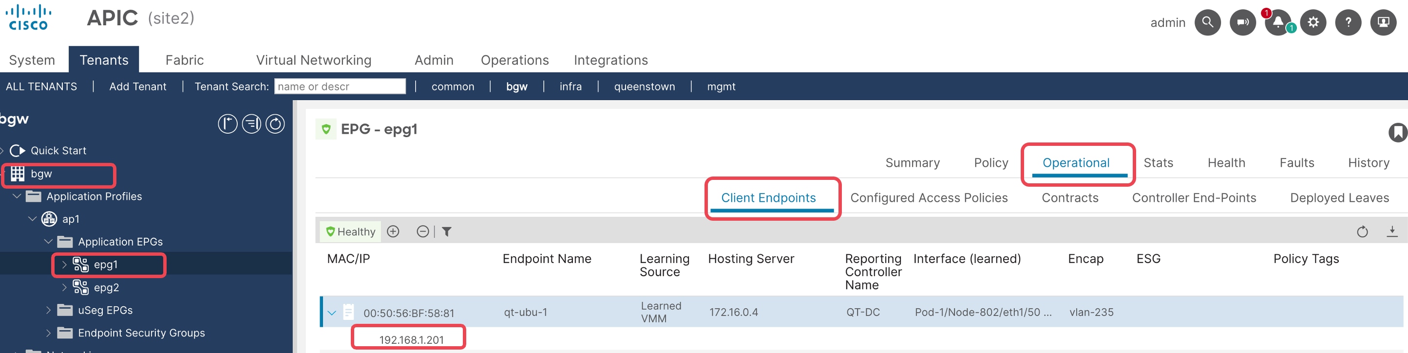
Figure 67. ACI Site 2 epg1 endpoints
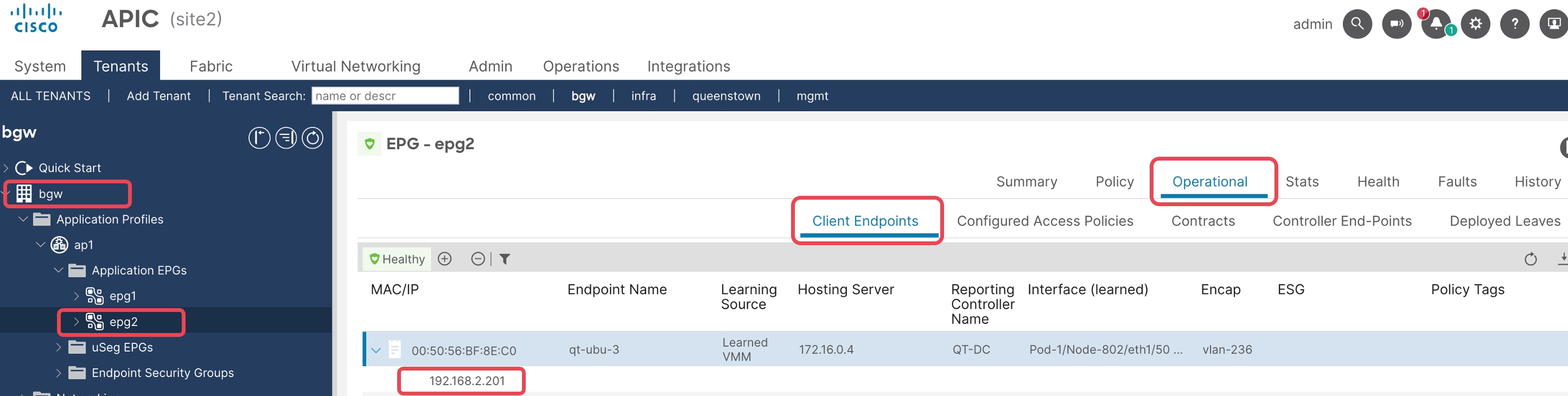
Figure 68. ACI Site 2 epg2 endpoints
Stretched VRF and Bridge Domain
The following figures show the configuration steps to stretch vrf1, then bd1 and bd2 for ACI Site 1. The process is the same on both sites.
Navigate to bgw tenant -> Networking -> VXLAN Stretch -> VRF Stretch -> “+” button.

Figure 69. ACI Site 1 stretch vrf1 step 1
On Create VXLAN VRF Stretch window, from drop-down menu, choose vrf1 and a Border Gateway Set, fill in 50001 as Normalized VNI, and then click Submit.
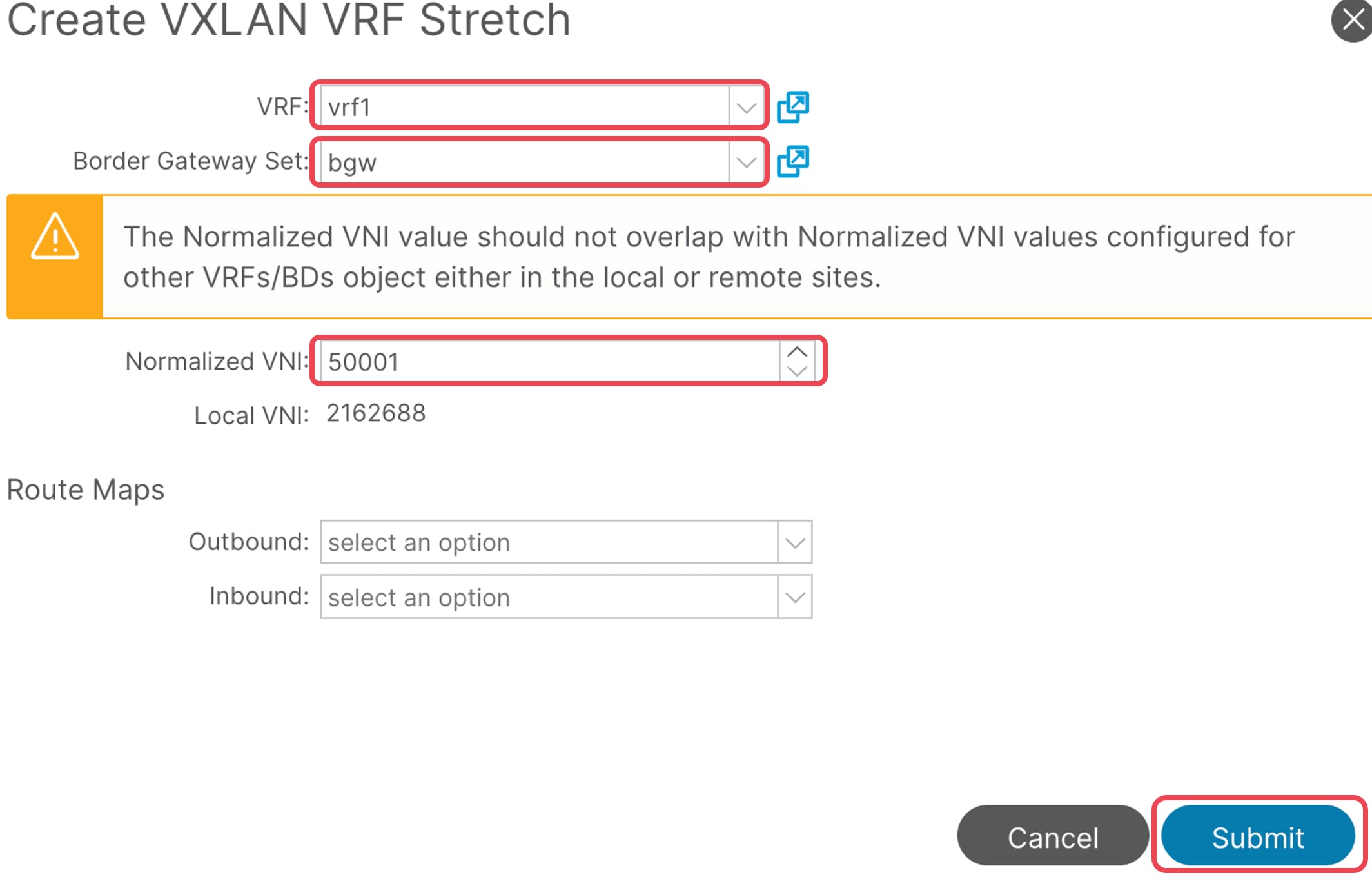
Figure 70. ACI Site 1 stretch vrf1 step 2
Now that vrf1 is stretched, it is visible within the VRF Stretch sub-menu.
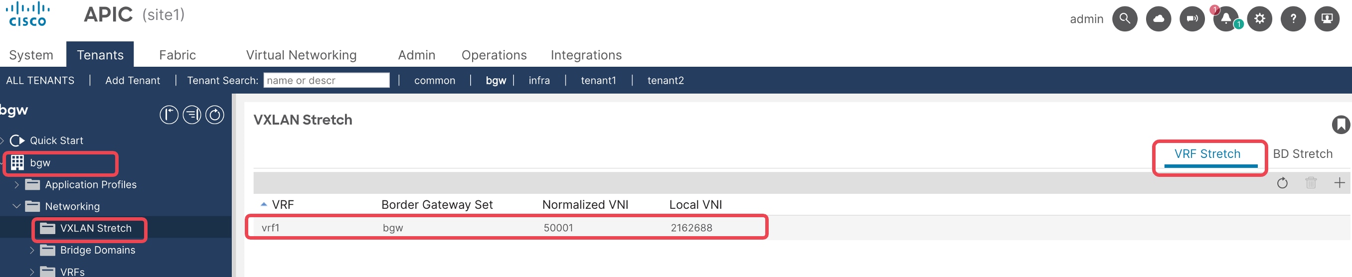
Figure 71. ACI Site 1 vrf1 stretched
Navigate to bgw tenant -> Networking -> VXLAN Stretch -> BD Stretch -> “+” button.

Figure 72. ACI Site 1 stretch bd1 step 1
On Create VXLAN BD Stretch window, from drop-down menu choose bd1 and a Border Gateway Set, fill in 30001 as Normalized VNI, and then click Submit.
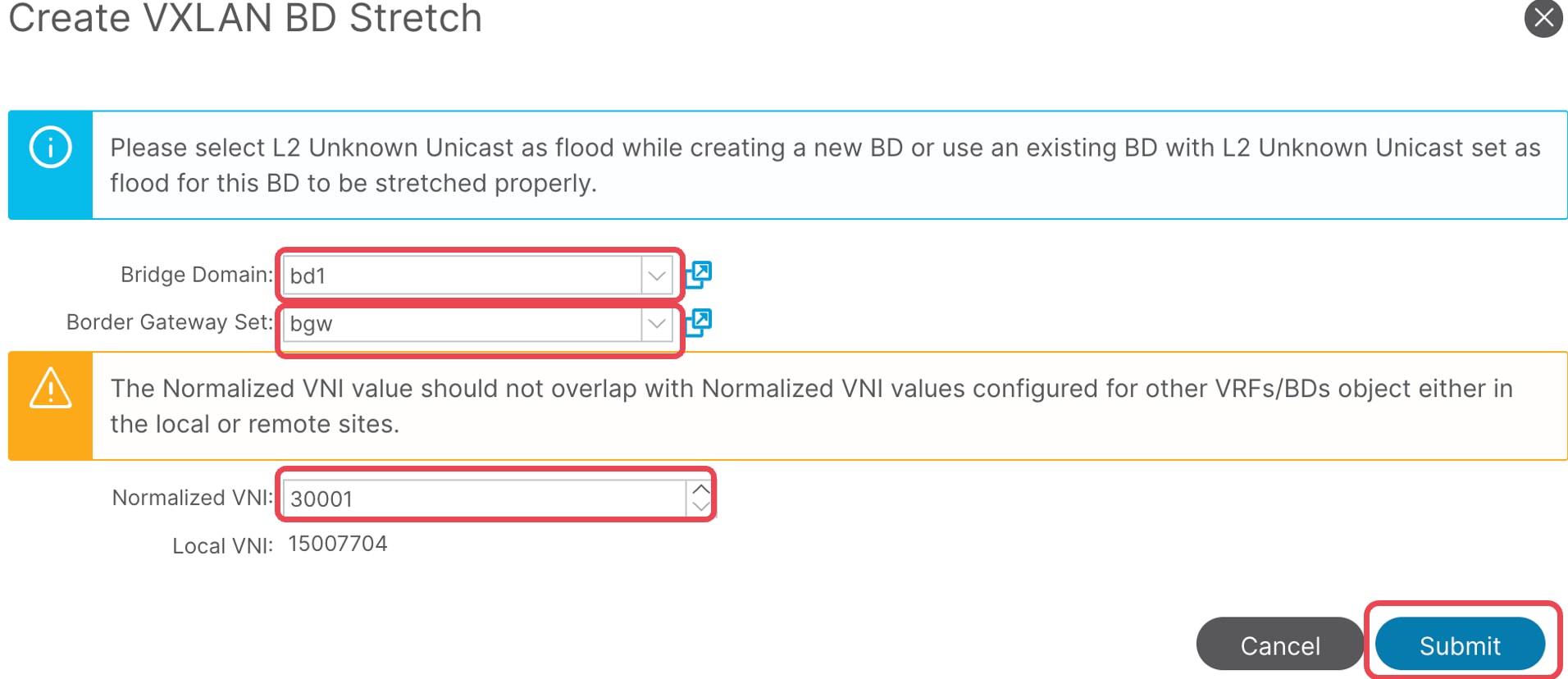
Figure 73. ACI Site 1 stretch bd1 step 2
Now that bd1 is stretched, it is visible within the BD Stretch sub-menu.

Figure 74. ACI Site 1 bd1 stretched
Follow similar process to stretch bd2 with 30002 as Normalized VNI. Below figure shows the result including both stretched bd1 and bd2.
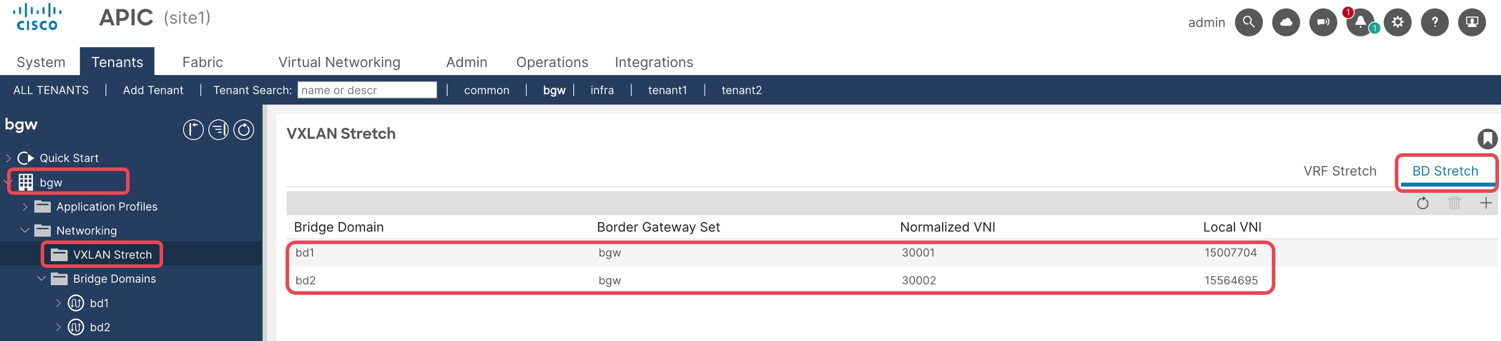
Figure 75. ACI Site 1 bd1 and bd2 stretched
The configuration process for ACI Site 2 follows the same steps as ACI Site 1. However, to make the object functionally stretched across the two APIC domains, the same Normalized VNI value must be configured on both sites. The following figures show the resulting configuration on ACI Site 2.

Figure 76. ACI Site 2 vrf1 stretched
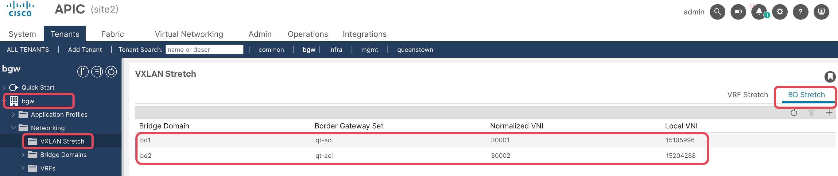
Figure 77. ACI Site 2 bd1 and bd2 stretched
The APIC user interface may vary slightly on different ACI versions. For instance, the VRF and BD stretch views do not display VNI information if your ACI version is prior to 6.2(1). To display detail info about VRF and BD VNI, you can double click on the entry below VRF Stretch and BD Stretch.
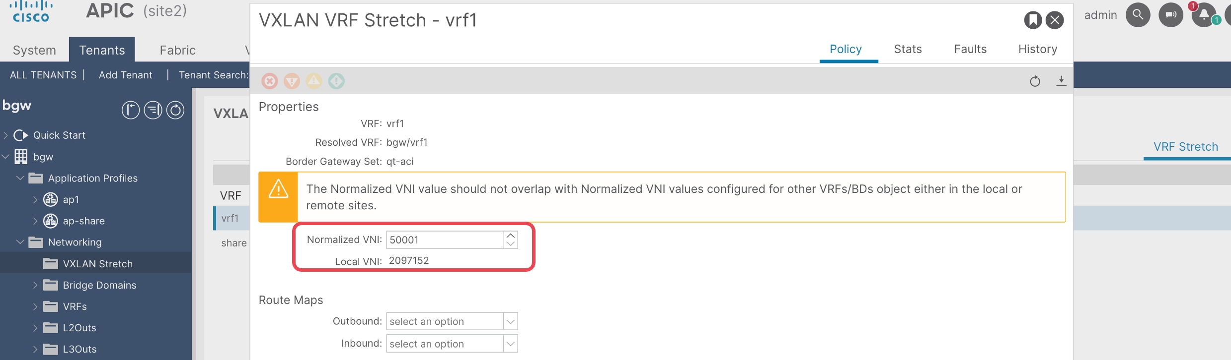
Figure 78. ACI Site 2 vrf1 Normalized VNI and Local VNI
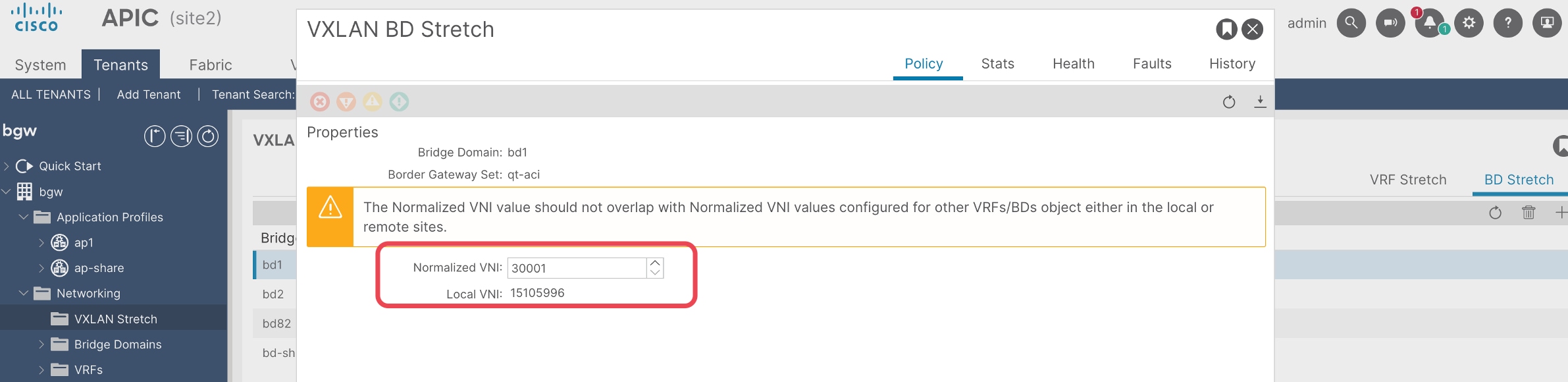
Figure 79. ACI Site 2 bd1 Normalized VNI and Local VNI
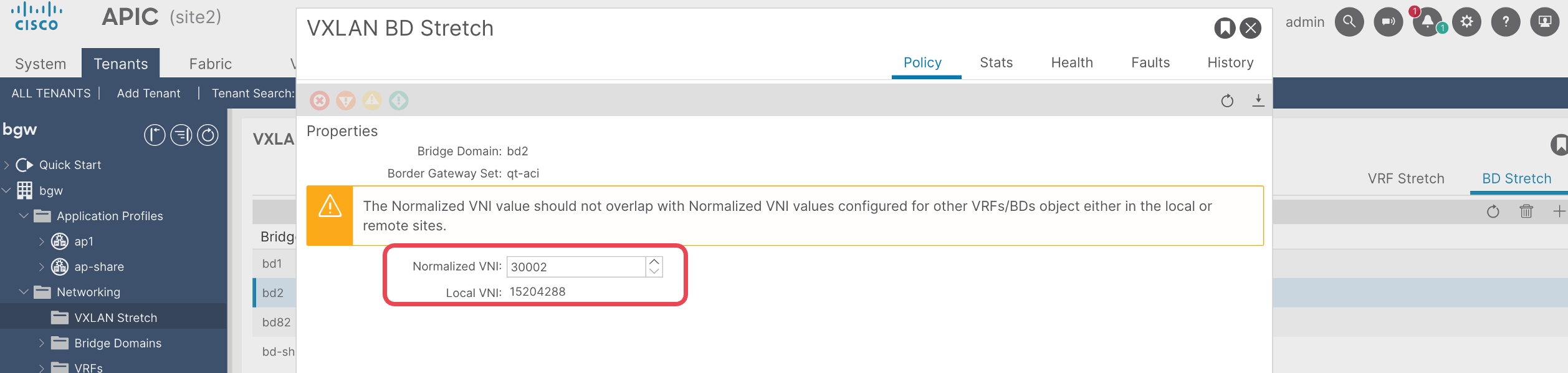
Figure 80. ACI Site 2 bd2 Normalized VNI and Local VNI
Once the VRF and BDs are stretched, they are deployed across all Border Gateways within the site’s Border Gateway Set. You may now proceed to the next section, which covers detailed use cases along with control plane and data plane verification. Any requirements for additional BD stretching will be explicitly mentioned within those specific use cases.
Use Case 1: Intra-Subnet Communication
Intra-subnet communication involves endpoints in the same subnet, regardless of whether they reside in a single or multiple ACI sites. Locally, endpoints in the same EPG communicate without contracts. For Multi-Site scenarios, however, you must migrate from EPGs to ESGs. This is typically done by creating an ESG and selecting an EPG as its member to ensure policy consistency across sites.
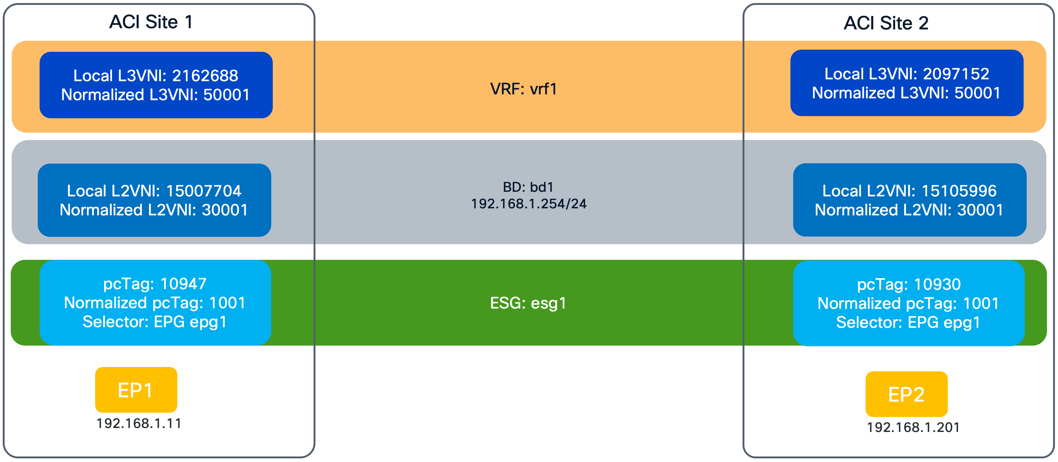
Figure 81. Intra-Subnet Communication
There are several key steps that must be performed across both ACI sites. It is assumed that the baseline tenant configuration is already complete, including the creation of Tenants, VRFs, BDs, Application Profiles, and EPGs, as well as the stretching of VRFs and BDs. The subsequent steps involve creating Endpoint Security Groups (ESGs) and configuring normalized pcTags to facilitate seamless end-to-end communication across the sites.
A script is available to assist with the EPG-to-ESG migration. The script can be accessed from the following GitHub repository: https://github.com/datacenter/ACI-ESG-Migration-Assistant
Each EPG or ESG is assigned with a unique pcTag, also known as a Class ID. Like the local VNI values used for stretched VRFs and BDs, pcTags are typically assigned locally within each APIC domain. As a result, the pcTag assigned to esg1 in ACI Site 1 may not match the pcTag assigned to esg1 in ACI Site 2.
To ensure consistent security enforcement across the multi-site domain, ACI uses a Normalized pcTag. In this example, the Normalized pcTag for esg1 is set to 1001 on both sites.
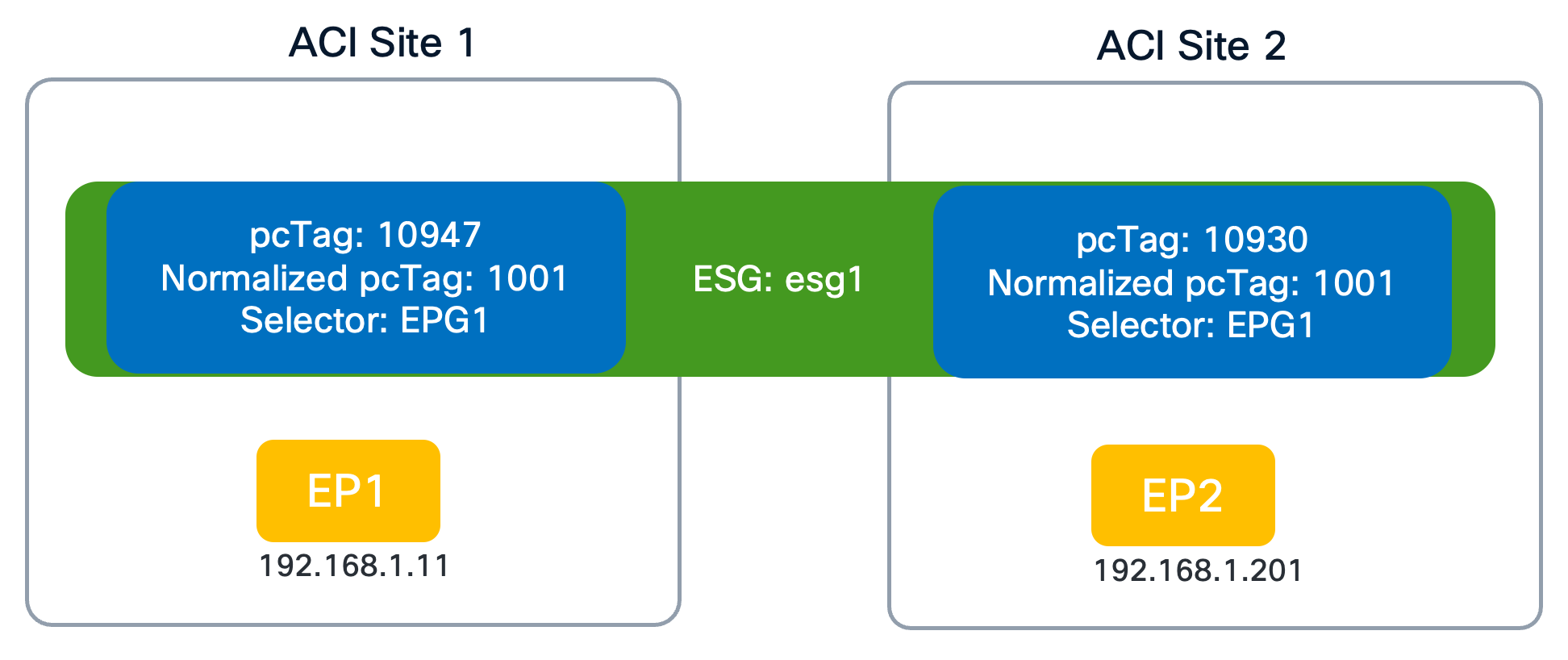
Figure 82. ESG esg1 pcTag and Normalized pcTag
By using this consistent global identifier, endpoints classified as part of esg1 across both sites are recognized as members of the same security group, allowing them to communicate without requiring a contract.
Within the BGW tenant on each ACI site, create an ESG named esg1. To do this, navigate to Endpoint Security Groups and select Create Endpoint Security Group from the Toolbox icon drop-down menu. Alternatively, right-click the Endpoint Security Groups folder in the left navigation pane and select Create Endpoint Security Group.
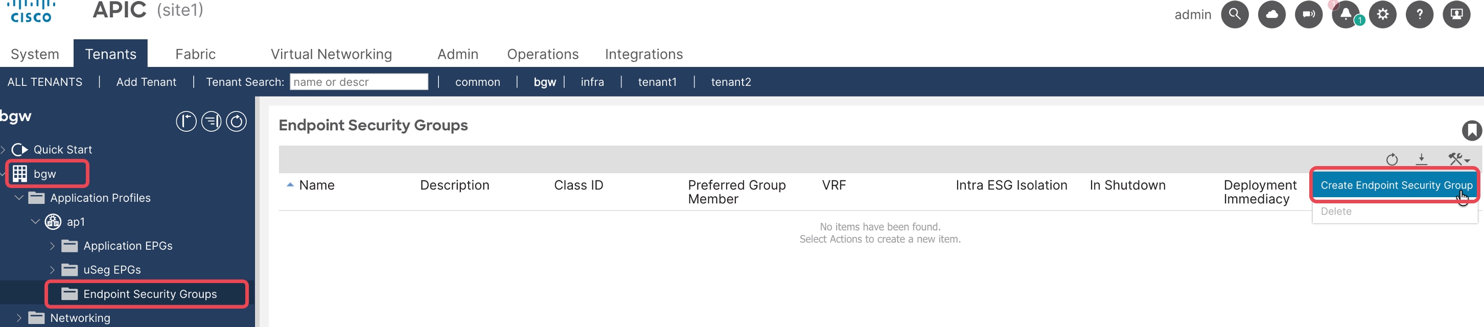
Figure 83. ACI Site 1 Create ESG step 1
Name the ESG “esg1” and select “vrf1” from the VRF dropdown menu. Click Next to proceed to the Selectors configuration.
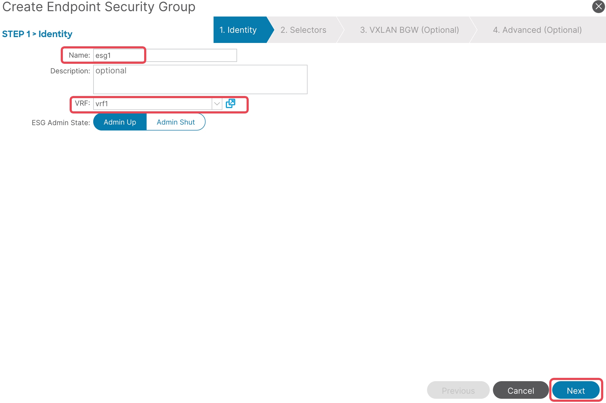
Figure 84. ACI Site 1 Create ESG step 2
Within the Selectors window, click the plus (+) icon on the right side of the EPG/External EPG/Selectors section to add a new selector.
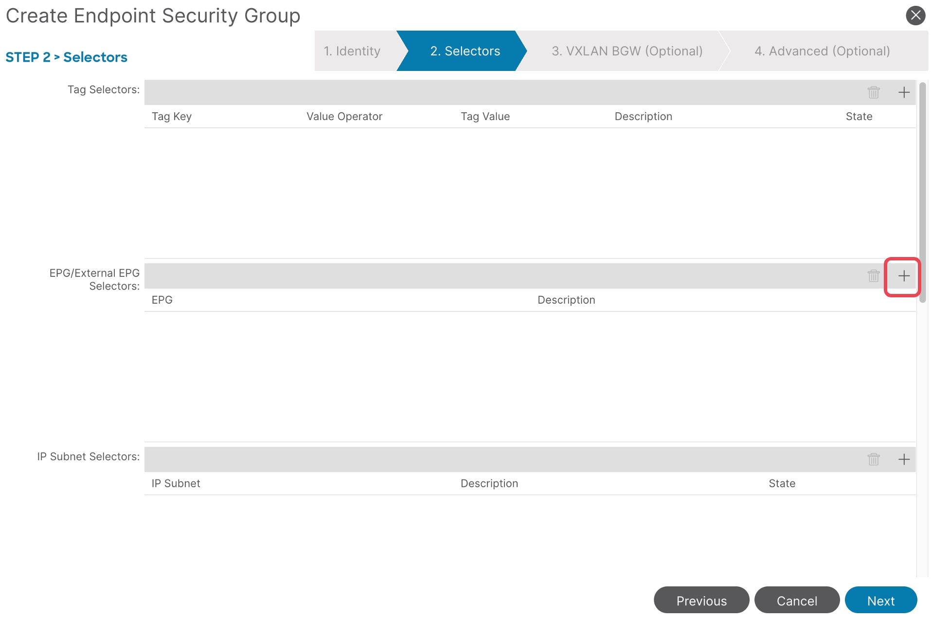
Figure 85. ACI Site 1 Add Selector step 3
In the Create an EPG/External EPG Selector window, select epg1 and click OK to proceed.
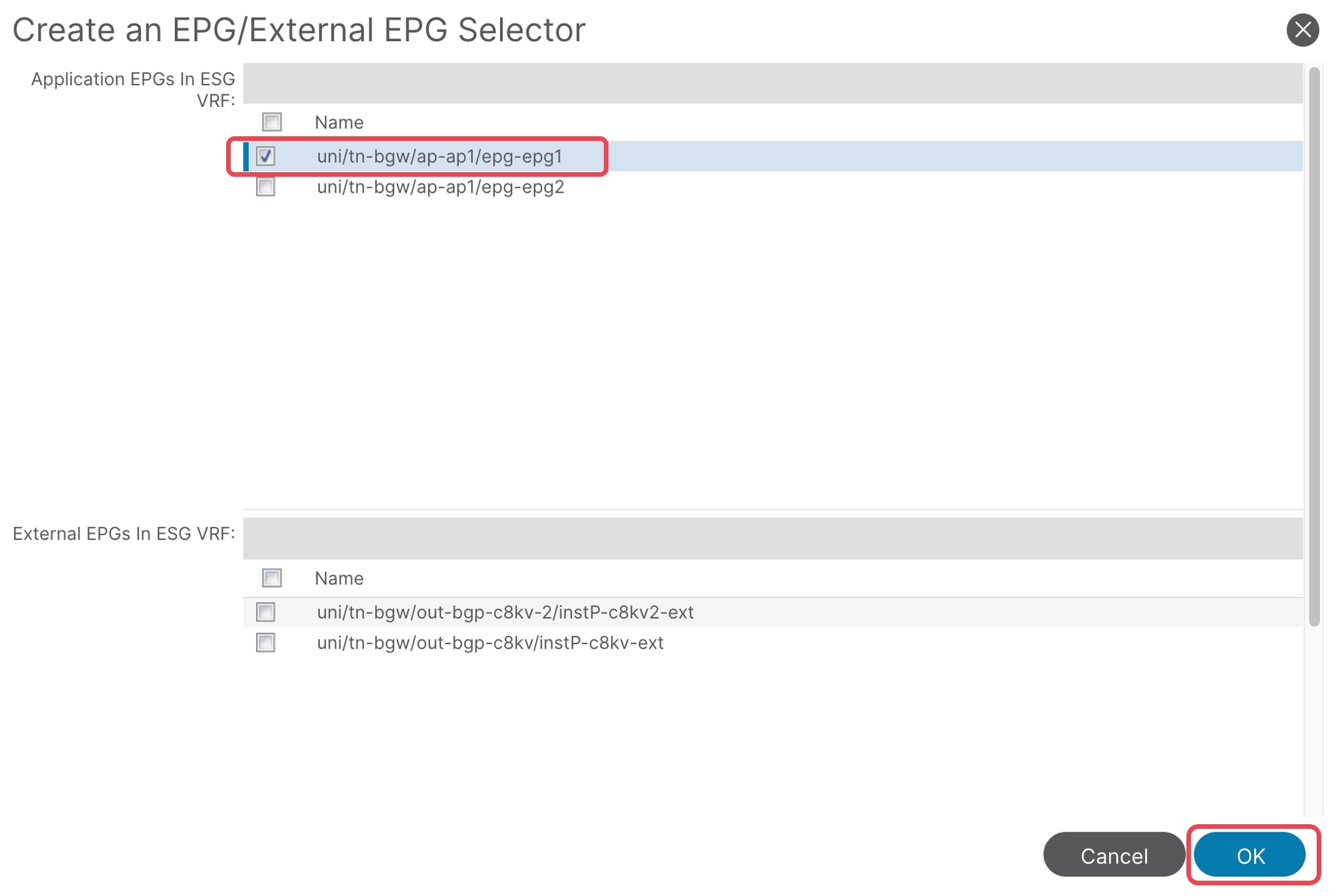
Figure 86. ACI Site 1 Choose epg1 as selector
After clicking OK, select Next to proceed to the VXLAN BGW (optional) window. Enter 1001 into the Normalized pcTag field.
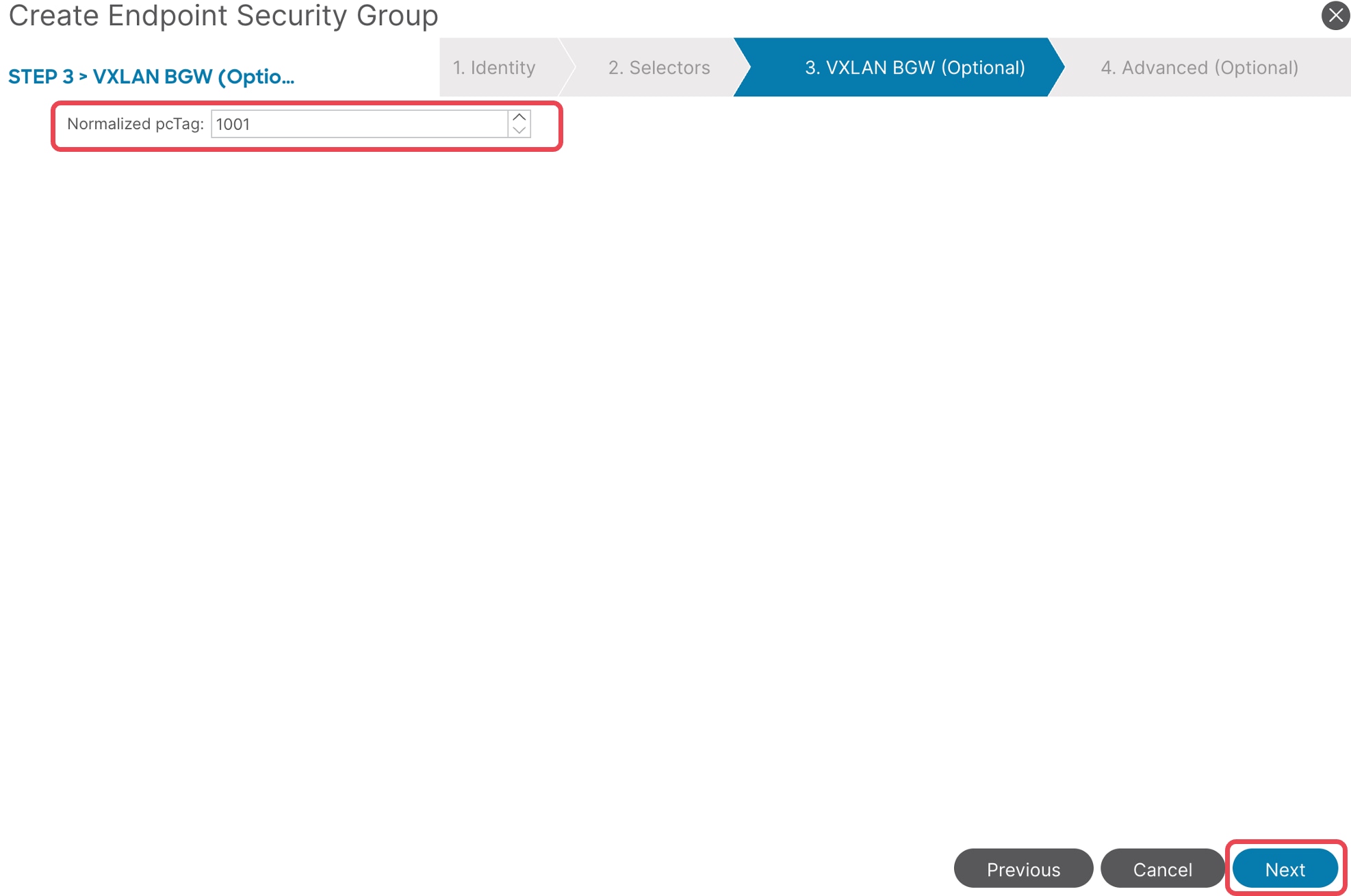
Figure 87. ACI Site 1 Set Normalized pcTag 1001
In the Advanced (optional) window, keep everything default. Adding an EPG to an ESG selector changes the pcTag assigned to the endpoints that match the selector. This policy reclassification may cause a temporary traffic outage while the endpoints are moved from the EPG to the ESG. Click Finish to complete.
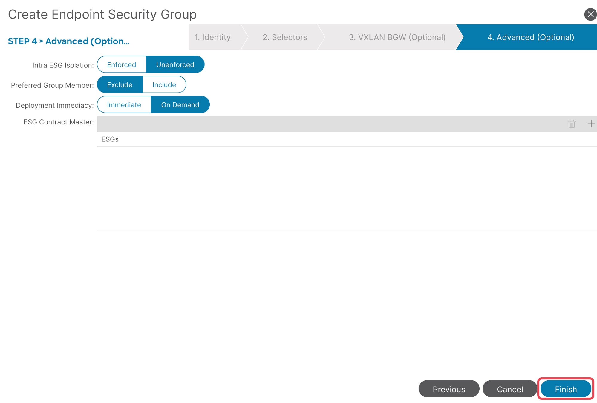
Figure 88. ACI Site 1 esg1 creation completion
Once created, you can review the information for esg1 and modify the configuration as needed. Note that the local pcTag value (e.g., 10947) is automatically assigned by the APIC during the creation process and cannot be manually changed. The most critical parameter is the Normalized pcTag, which must be identical for esg1 across both ACI sites. If you need to update the normalized pcTag for an existing ESG, ensure that the Set Normalized pcTag checkbox is selected before entering the value.
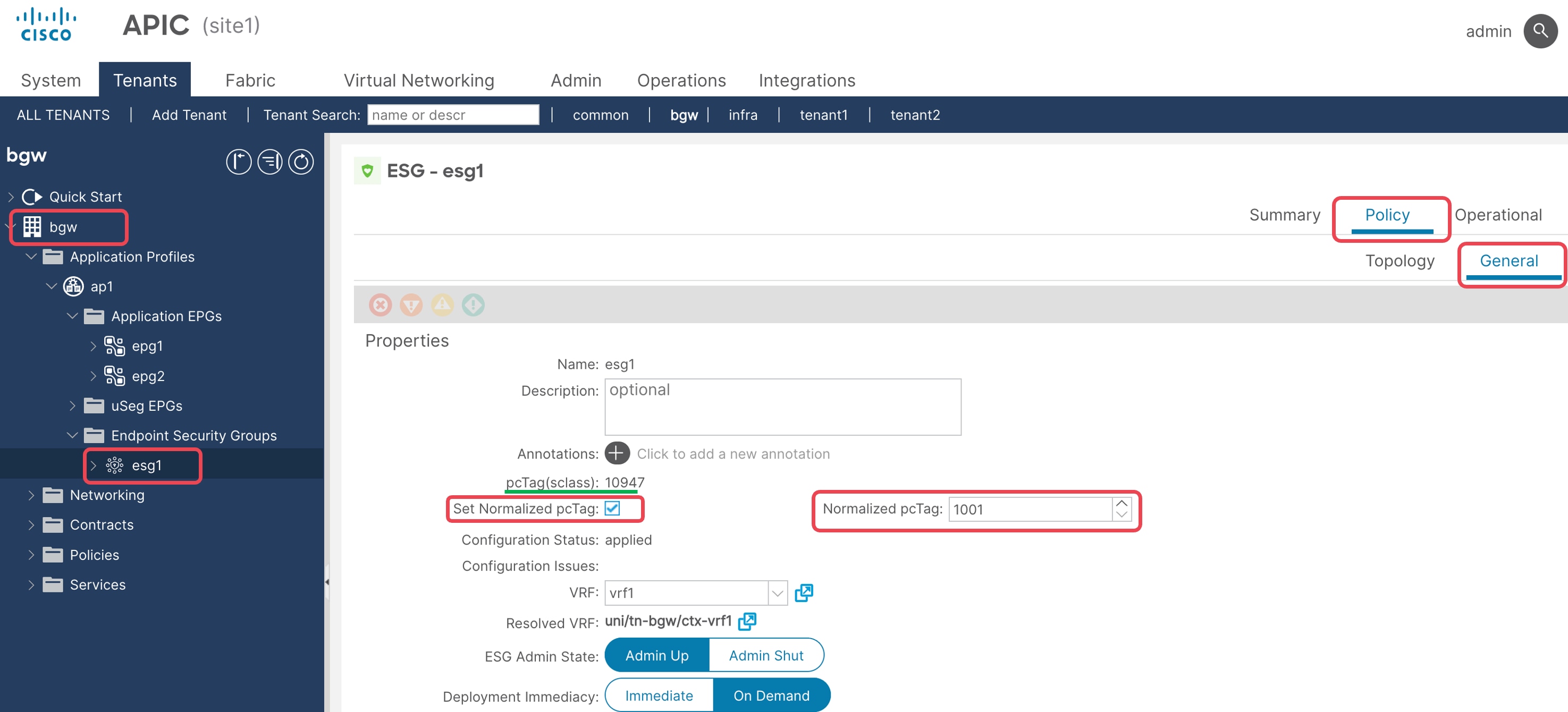
Figure 89. ACI Site 1 esg1 general information
The figure below displays the selectors for esg1. You can update a selector by right clicking the relevant entry in the left navigation pane.
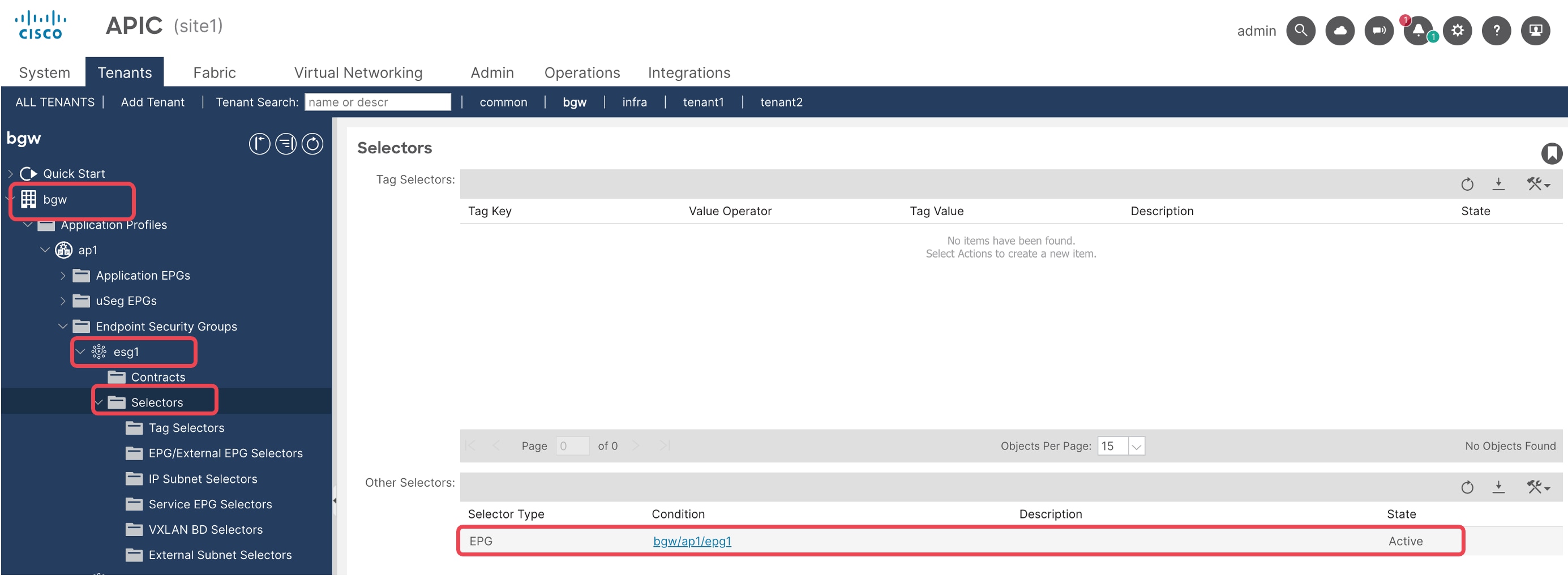
Figure 90. ACI Site 1 esg1 selectors
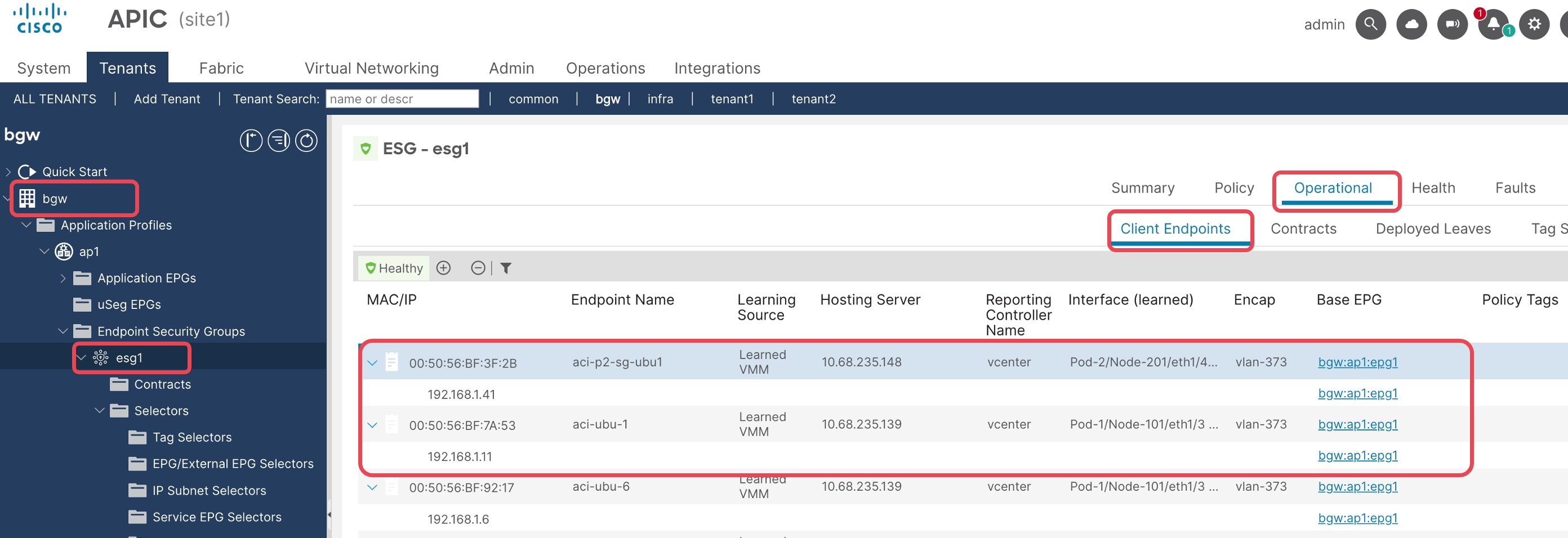
Figure 91. ACI Site 1 esg1 endpoints
The process for creating esg1 on ACI Site 2 is identical. The following image illustrates the resulting configuration for esg1 on the second site.
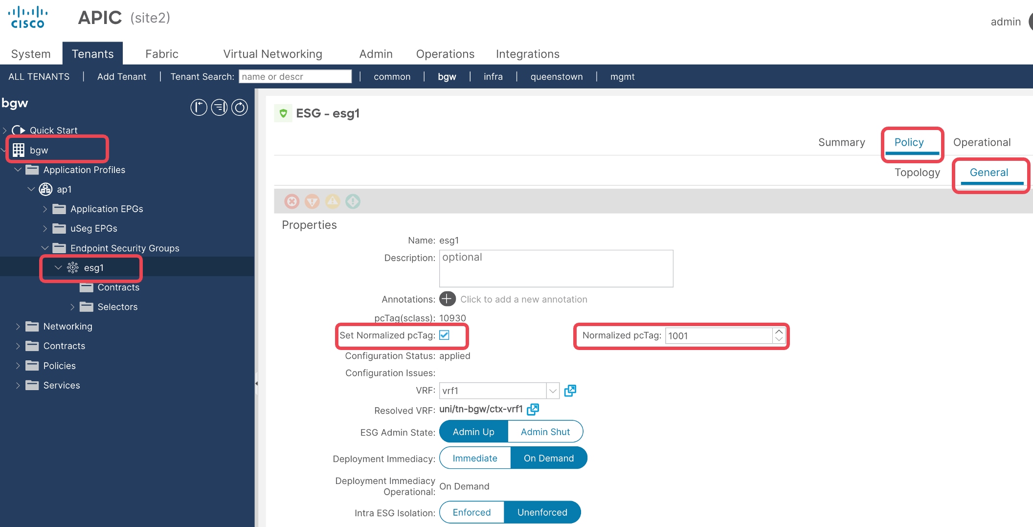
Figure 92. ACI Site 2 esg1 general information
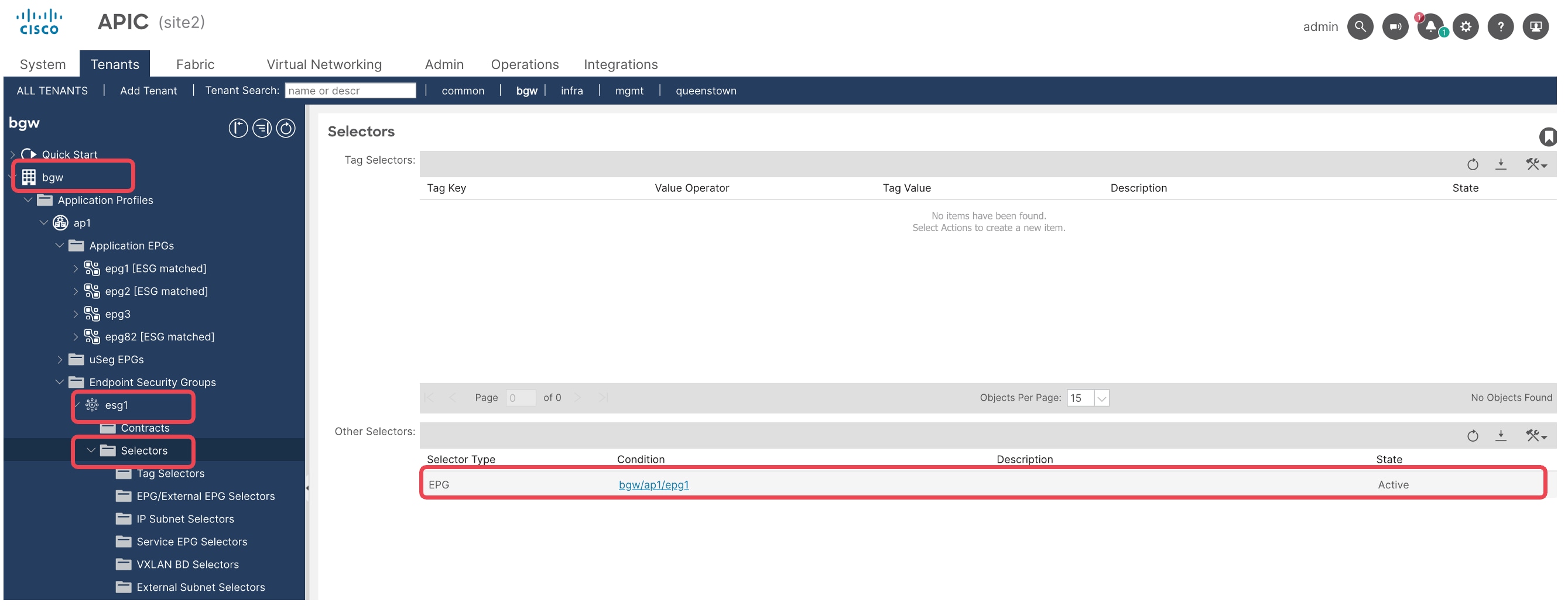
Figure 93. ACI Site 2 esg1 selectors
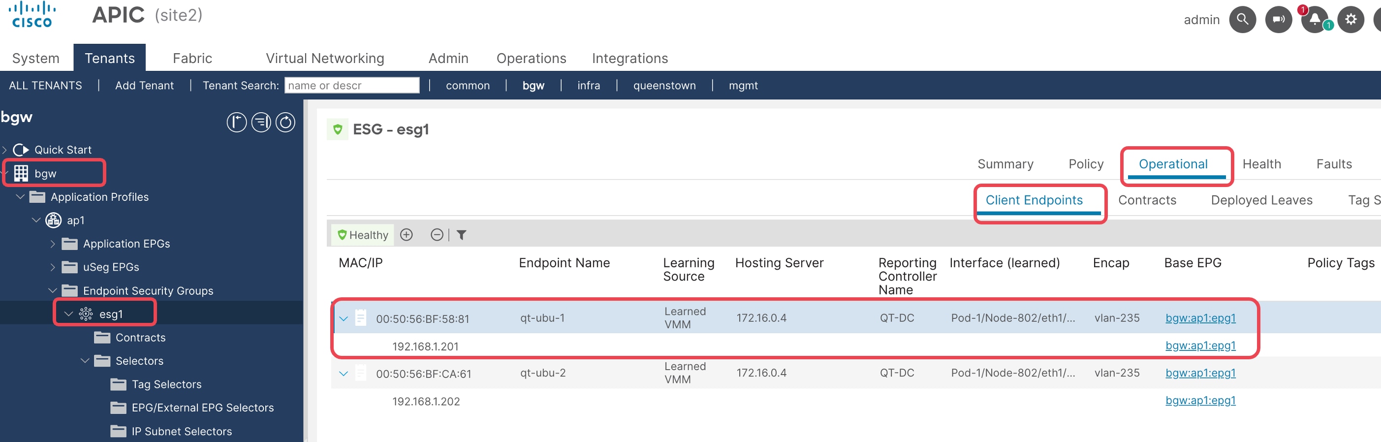
Figure 94. ACI Site 2 esg1 endpoints
Control Plane Verification
This section is intended for advanced users seeking a technical deep dive into how routing and policy enforcement function across the site. At a high level, the block diagram below illustrates the control plane advertisement from ACI Site 1 to ACI Site 2. The same process occurs in reverse, from ACI Site 2 to ACI Site 1.
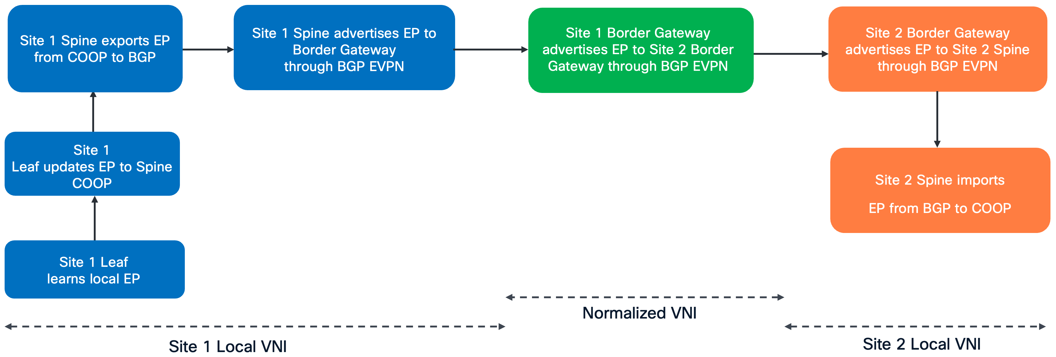
Figure 95. Control Plane across sites
To ensure clarity, the topology diagram illustrates only the essential devices required for this specific configuration.
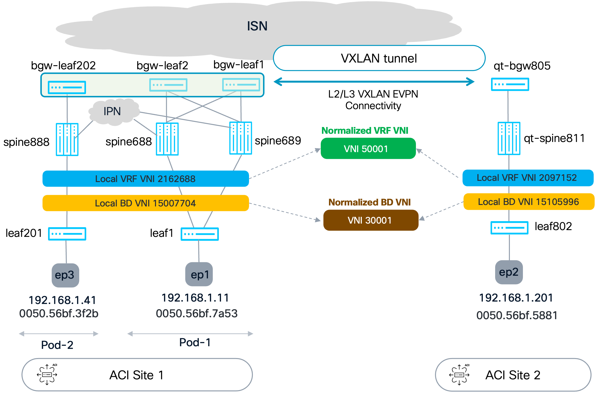
Figure 96. Control Plane verification topology
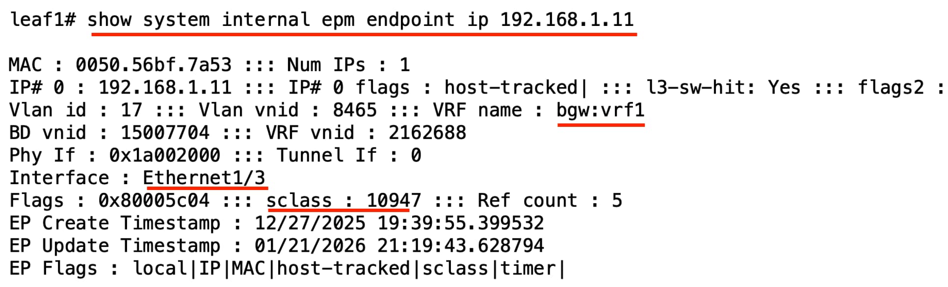 |
Leaf1 on ACI Site 1 learns endpoint MAC address 0050.56bf.7a53.
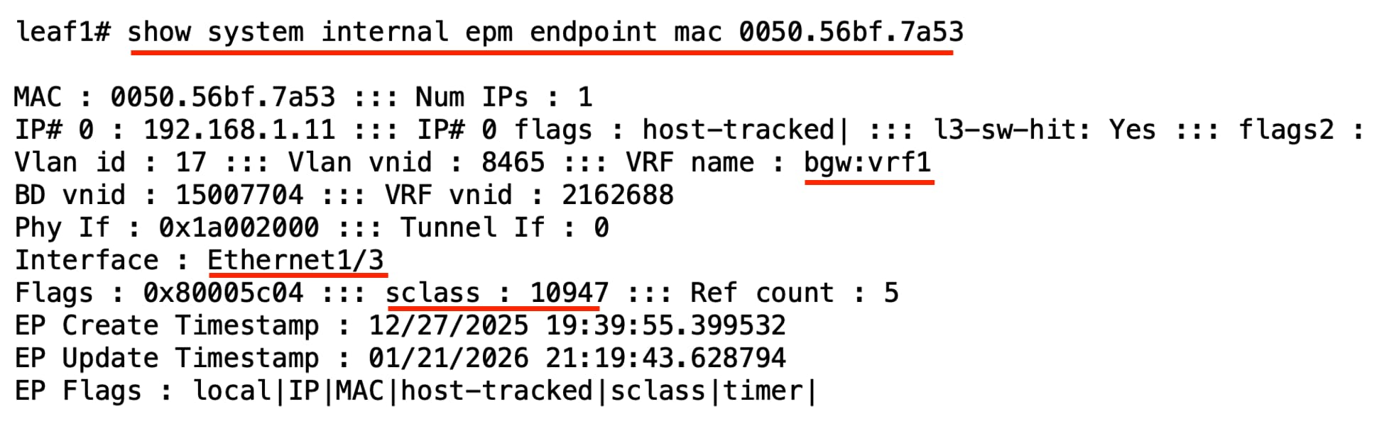
Figure 97. ACI Site 1 - leaf1 learns local endpoint MAC address
When bd1 is configured as Layer 3 BD with unicast routing enabled, Leaf1 learns IP address 192.168.1.11 as well.
Figure 98. ACI Site leaf1 learns endpoint IP address
Verify the COOP entry for the endpoint MAC address on one of the spines. The value 15007704 represents the local VNI for bd1 in ACI Site 1. Note that the COOP output has been truncated to show only the relevant information. For reference, the PcTag value 0x1002ac3 can be converted to decimal by removing the “0x1” prefix and converting “002ac3” from hexadecimal to decimal. This results in 10947, which correctly matches the esg1 pcTag.
Figure 99. Local endpoint COOP entry
In the same output, the IN_OBJ EXPORT flag indicates that this COOP entry has been exported to the BGP process.
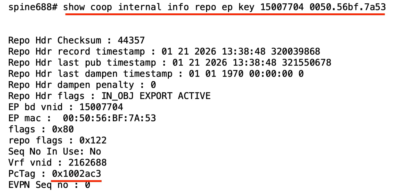
Figure 100. COOP exports to BGP
ACI Site 1 spines advertise local endpoint information to the ACI Site 1 Border Gateways and to spine switches in other pods, such as Pod-2 in this example. This is standard ACI Multi-Pod behavior and is not specific to the Border Gateway implementation.
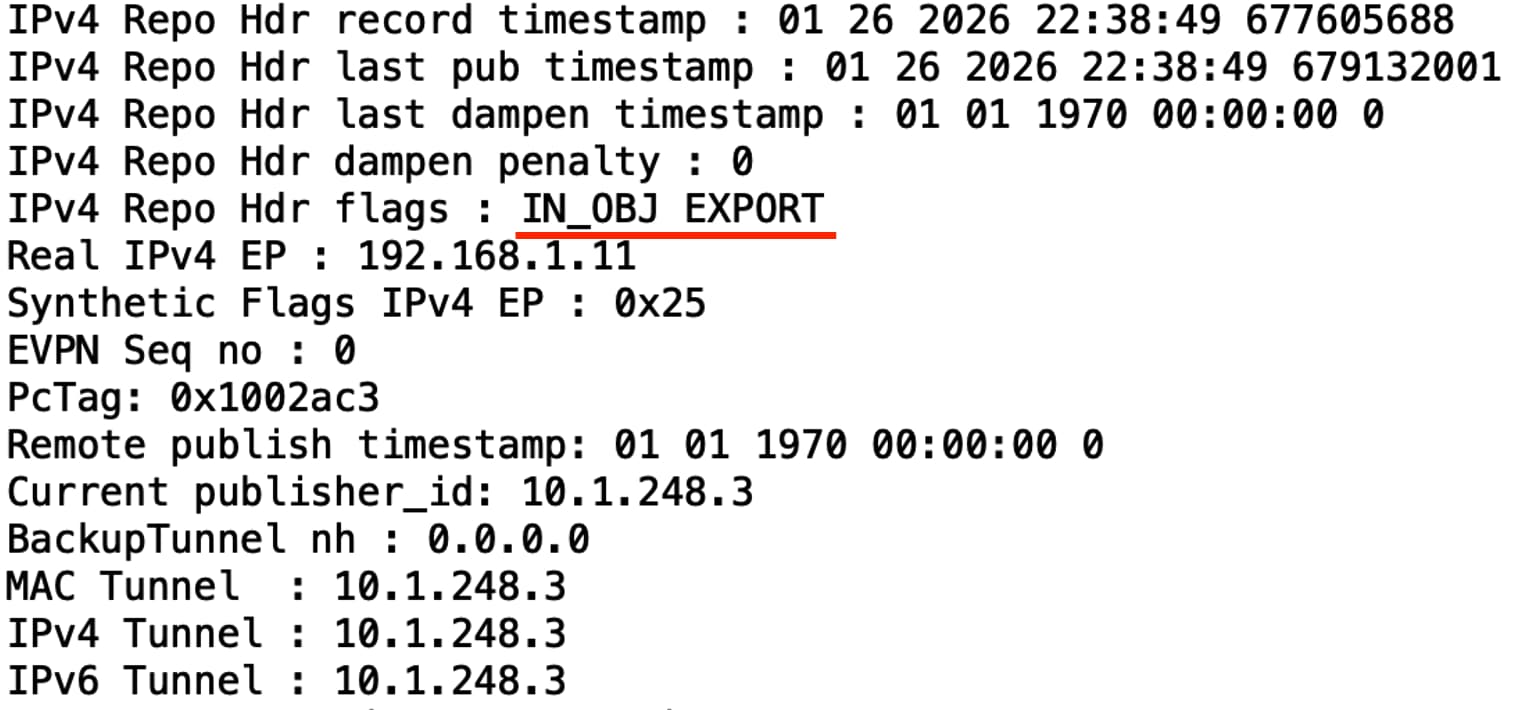
Figure 101. ACI Site 1 - Spine advertises local EP to Border Gateways and Spine in another Pod
Note that the local pcTag 10947 is included in the BGP EVPN update.
After the Border Gateway in the same pod receives the endpoint information, it advertises this information to the Border Gateway in the remote ACI site (ACI Site 2 in this example) using the Normalized VNI and Normalized pcTag.
Note that the CLI output on the local Border Gateway, in this case the Border Gateway in ACI Site 1, currently displays the local VNI and local pcTag values. In the screenshot below, 15007704 represents the local VNI configured in ACI Site 1, and 10947 represents the local pcTag assigned to esg1. The corresponding normalized values are observed on the remote Border Gateway in ACI Site 2 by issuing command in vsh mode.
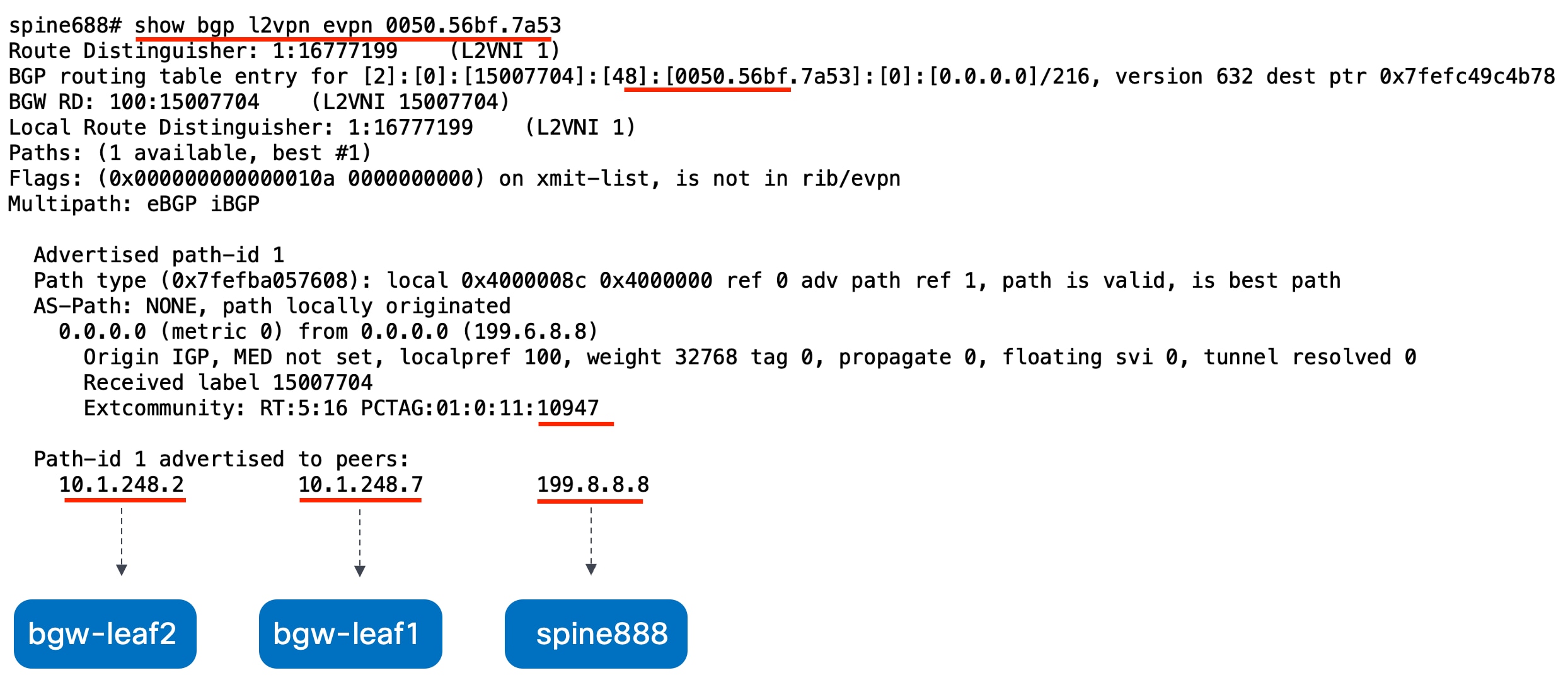
Figure 102. ACI Site 1- Border Gateway advertises endpoint to ACI Site 2 Border Gateway
ACI Site 2 Border Gateway receives endpoint information via a BGP EVPN Type-2 update. Subsequently, this endpoint information is forwarded to the ACI Site 2 spine using BGP EVPN Type-2, with the pcTag updated to 10930, which corresponds to the local pcTag for esg1 in Site 2. The screenshot below taken from ACI Site 2 Border Gateway shows the remote endpoint EVPN Type-2 route learned the remote ACI site (ACI Site 1). The route is first displayed under the remote Route Distinguisher, 100:31784920, with paths learned from the Border Gateways in ACI Site 1. In this section of the output, the route carries the normalized VNI and pcTag information received from ACI Site 1 Border Gateways.
In the following output, “Received label 30001” represents Normalized BD VNI. The pcTag value 1001 represents Normalized esg1 pcTag.
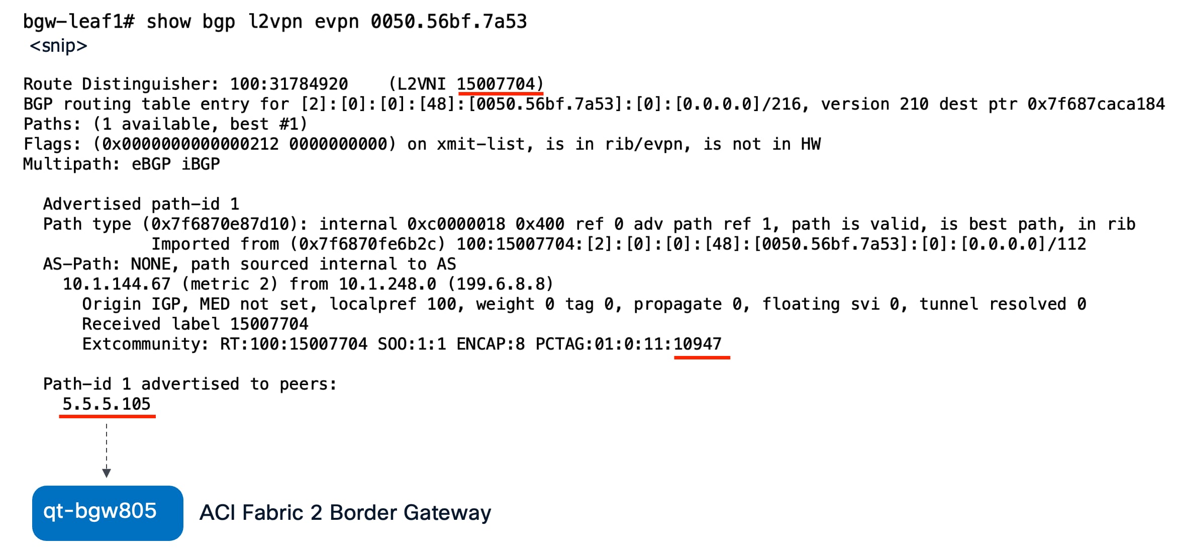
Figure 103. ACI Site 2 Border Gateway received section of EVPN Route
In the same CLI output, the same route is then imported into the local site context under Route Distinguisher 400:31883212 and local L2VNI 15105996. The “Imported from” field identifies the original remote EVPN route, while the “Path-id 1 advertised to peers” field confirms that the imported route is advertised to the local spine peer, 10.118.112.65. The value 10930 represents the esg1 local pcTag.
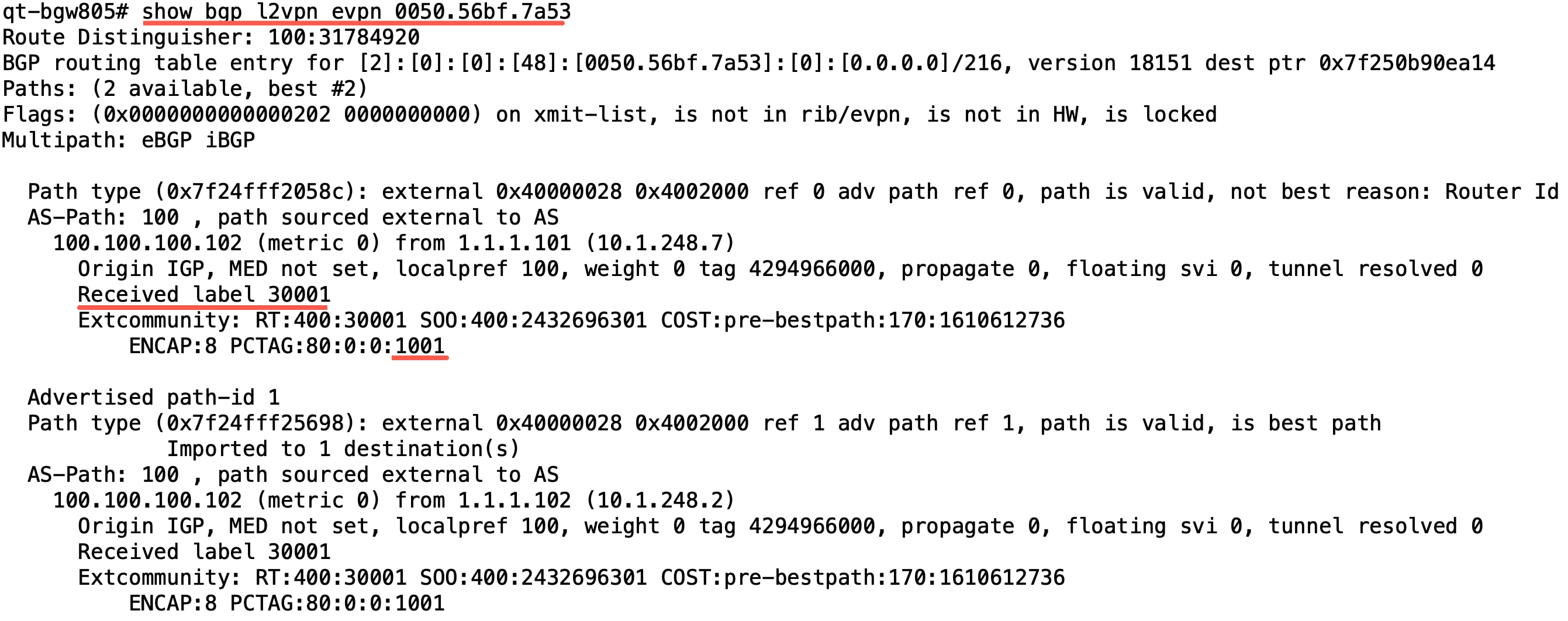
Figure 104. ACI Site 2 Border Gateway receives endpoint information through BGP EVPN update
ACI Site 2 spine receives endpoint information through BGP EVPN update from ACI site 2 Border Gateway, subsequently it imports endpoint information to spine COOP.
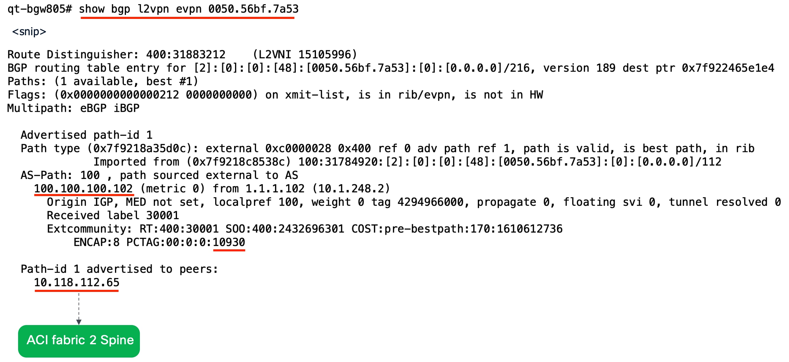
Figure 105. ACI Site 2 spine receives endpoint information from Border Gateway through BGP EVPN update
As shown in the figure above, ACI Site spine receives endpoint information from the Border Gateway via a BGP EVPN update. This is indicated by the output line “from 10.118.112.67”, which refers to the Border Gateway PTEP. The spine then imports this information into its COOP database.
ACI Site spine now has endpoint information in its COOP database. On Site 2 spine:
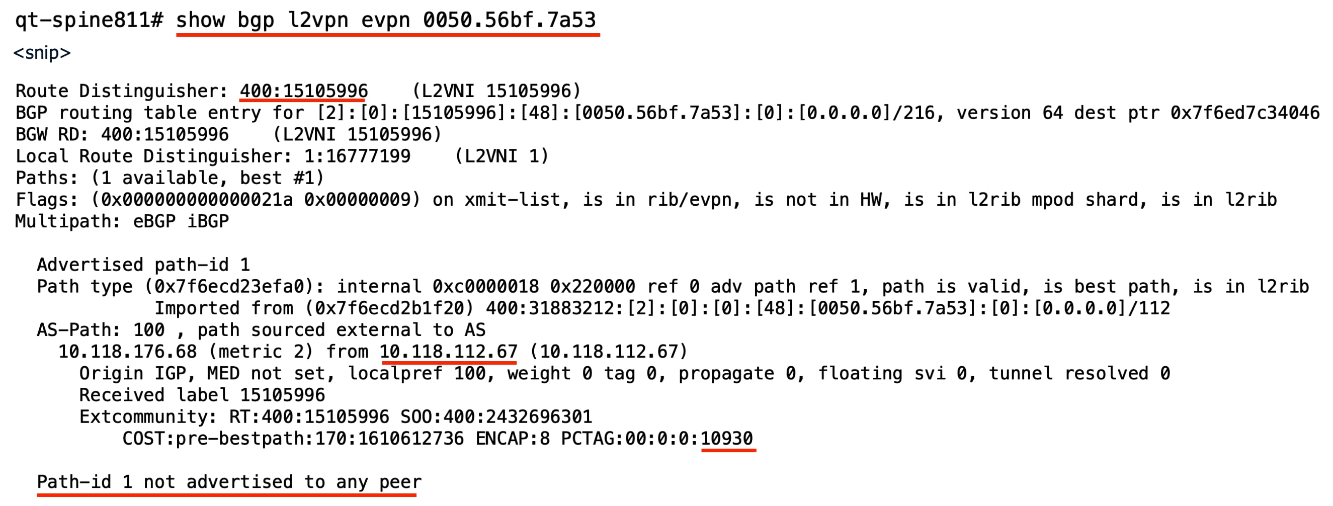
Figure 106. ACI Site 2 spine COOP entry of remote endpoint
Keep in mind that the Bridge Domain (BD) VNID is 15105996, which is the local VNID for bd1 on ACI Site 2. In the COOP entry, “Remote Type: External Site” indicates that this endpoint originates from a remote site (ACI Site 1). We can derive the pcTag in decimal from the value “PcTag: 0x1002ab2” by converting the hexadecimal portion “002ab2” to decimal. The result is 10930, which corresponds to the local pcTag of esg1 configured on ACI Site 2. The tunnel next-hop, 10.118.176.68, represents the internal VXLAN anycast address.
At this stage the control plane information of endpoint in ACI Site 1 has been sent successfully to ACI Site 2. In the reverse direction endpoint information from ACI Site 2 is also sent to ACI Site 1.
Data Plane Verification
Communication occurs between two endpoints, EP-1 and EP-2, residing in the same stretched Bridge Domain but on different ACI Sites. In this example EP-1 resides in ACI Site 1 Pod-1, EP-2 resides in ACI Site 2 Pod-1. The Normalized VNI 30001 is defined by the administrator by configuring the normalized BD VNI when stretching the BD across the sites.
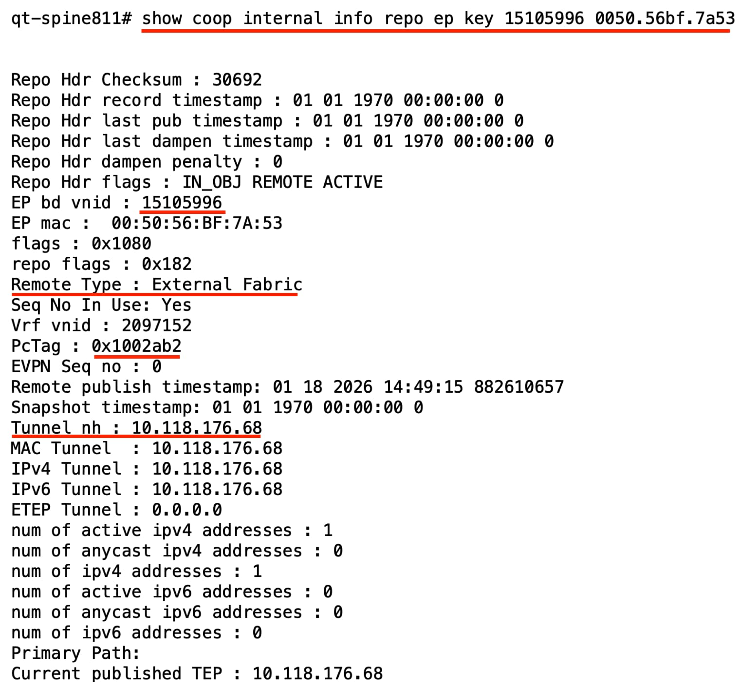
Figure 107. Data plane Bridged Communication across sites
From endpoint in esg1 ACI Site 1 ping endpoint in esg1 ACI Site 2.
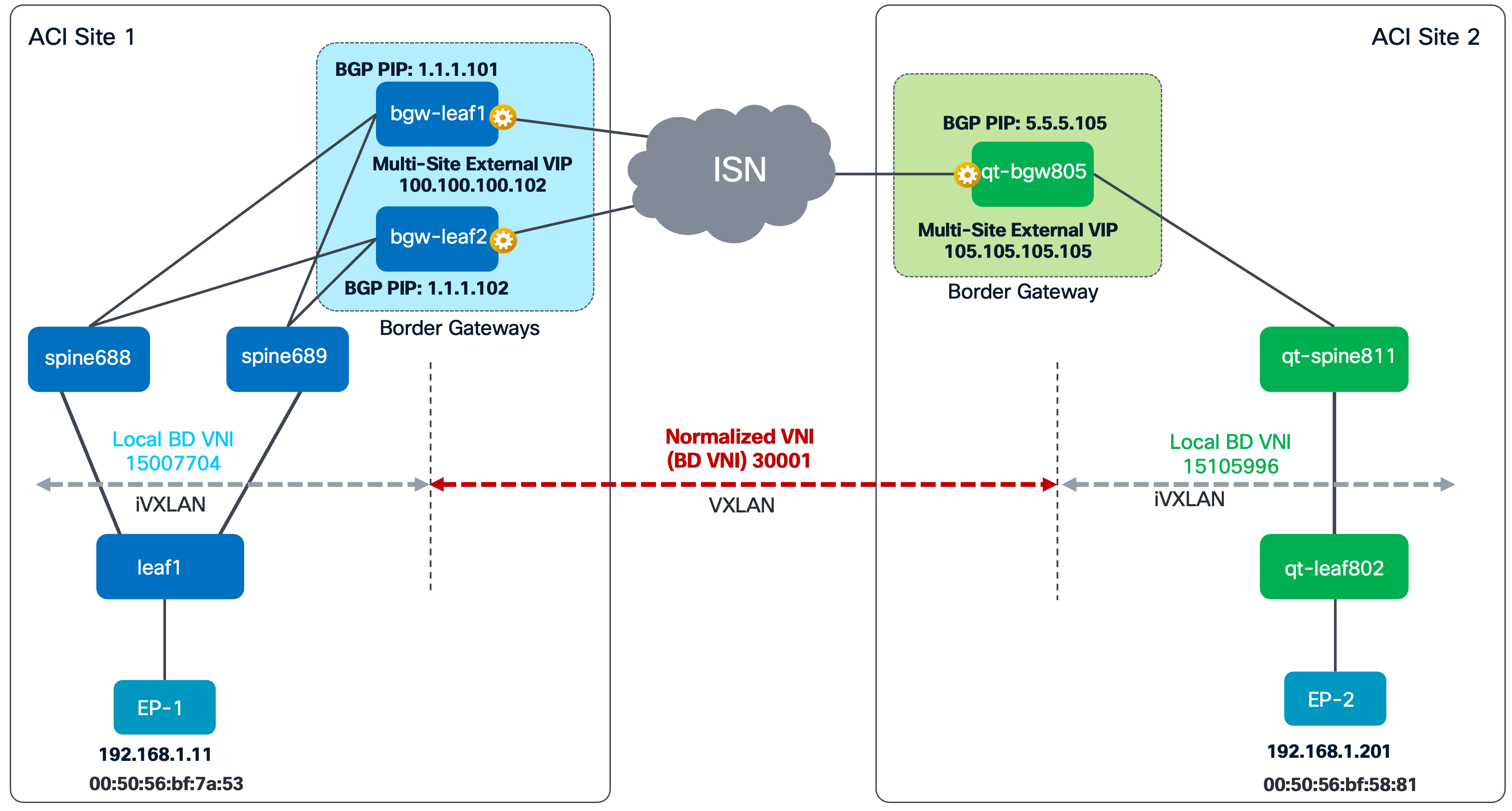
Figure 108. Endpoint in esg1 ACI Site 1
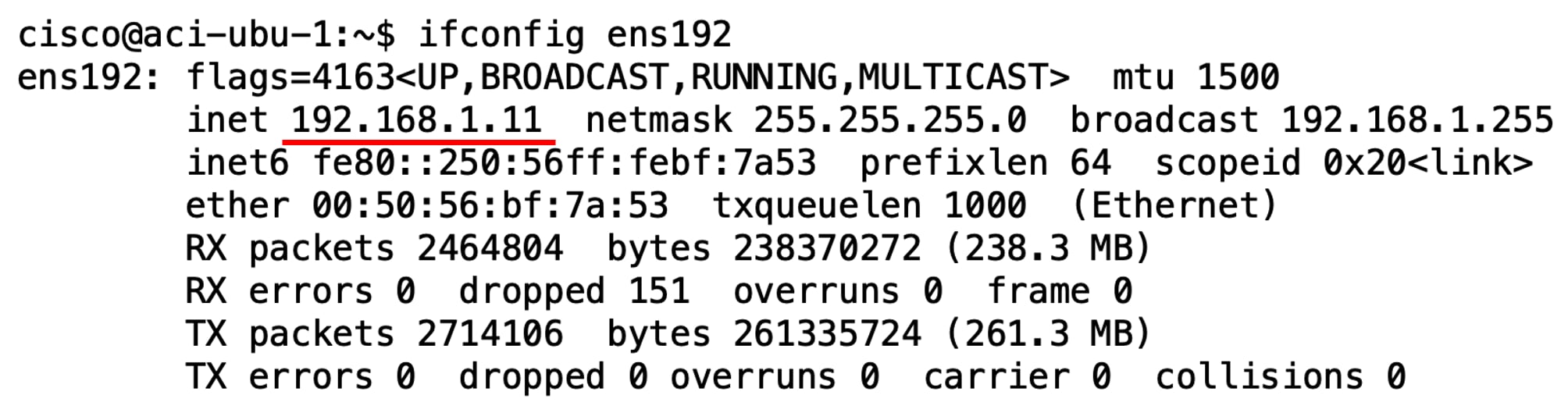
Figure 109. Ping from endpoint in esg1 ACI Site 1 to endpoint in esg1 ACI Site 2
The following packet capture was obtained via ERSPAN traffic from ISN device.
The packet capture of the ICMP request from EP-1 to EP-2 confirms that the Layer 2 (BD) Normalized VNI is used in the VXLAN header for inter-site data plane forwarding.
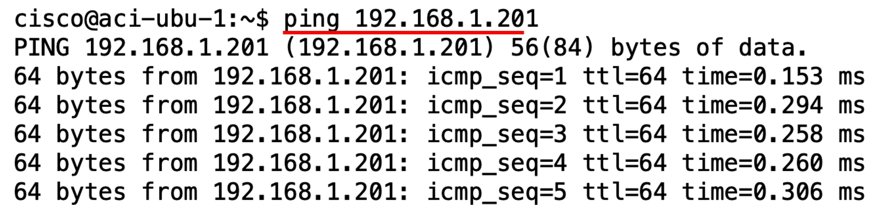
Figure 110. ICMP request from EP-1 (192.168.1.11) to EP-2 (192.168.1.201)
As illustrated in the figure above, an ICMP packet originating from source 192.168.1.11 (EP-1) destined for 192.168.1.201 (EP-2) is encapsulated in standard VXLAN using the standard destination UDP port 4789.
The VXLAN header confirms that the VNI value is 30001, which matches the value configured by the administrator. Of particular interest is the Group Policy ID field, which is set to 0.
To understand the significance of this, it is important to note how the Group Policy ID is used in standard ACI intra-site traffic. Within an ACI fabric, intra-site traffic uses the iVXLAN header, which carries a non-zero Group Policy ID value. This value is also referred to as the Policy Control Tag (pcTag) and represents the EPG/ESG membership of the endpoint. The pcTag is used for policy enforcement to determine whether traffic should be permitted or dropped.
In the ACI Border Gateway implementation, the Group Policy ID (pcTag) is set to 0 in the VXLAN header whenever the Border Gateway sends traffic out of its local site. This is by design rather than relying on the Group Policy ID field for policy enforcement, the BGW leverages the BGP EVPN control plane to carry both routing information and pcTag information within the BGP EVPN route attributes. The policy enforcement decision is therefore made based on the information exchanged through the BGP EVPN control plane, rather than carried via the VXLAN data plane header.
The figure above also illustrates the VXLAN tunnel source address as 1.1.1.102, which is the BGW Primary IP (PIP) also referred to as the EVPN Loopback IP of the second Border Gateway in ACI Site 1. The VXLAN tunnel destination is the Multi-Site External Anycast IP of the Border Gateways in ACI Site 2, Pod-1.
It is important to note that the selection of the VXLAN tunnel source, specifically which Border Gateway PIP is used, is determined by a hashing algorithm. Intra‑fabric ECMP determines the path between the local leaf and the local Border Gateway. If multiple Border Gateways exist within the same ACI Pod, the intra‑fabric ECMP selects one based on the hash outcome. Once the selected Border Gateway receives the flow, it sources the VXLAN tunnel using its own PIP and forwards the packet toward the remote Border Gateways’ Multi‑Site External VIP.
The packet capture of the ICMP reply from EP-2 to EP-1 confirms that the Layer 2 (BD) Normalized VNI is used in the VXLAN header for inter-site data plane forwarding.
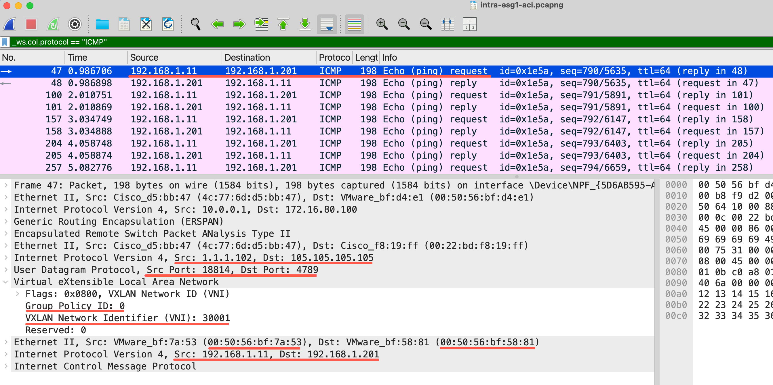
Figure 111. ICMP reply from EP-2 (192.168.1.201) to EP-1 (192.168.1.11)
The information displayed in the ICMP reply capture is almost identical to that of the request. One of the most notable differences is that the VXLAN tunnel source address is now 5.5.5.105, which is the BGW Primary IP (PIP) of the first Border Gateway in ACI Site 2. The VXLAN tunnel destination address is 100.100.100.102, which is the Multi-Site External Virtual IP (VIP) of the Border Gateways in ACI Site 1, Pod-1.
It is important to note that the Multi-Site External VIP is unique per ACI Pod. Therefore, traffic returning from ACI Site 2 is always destined for the Multi-Site External VIP associated with the specific Pod in ACI Site 1 from which the original request was sourced.
The figure below illustrates the policy enforcement locations for intra-subnet communication. The same logic applies for returning flow from ACI Site 2 to ACI Site 1.
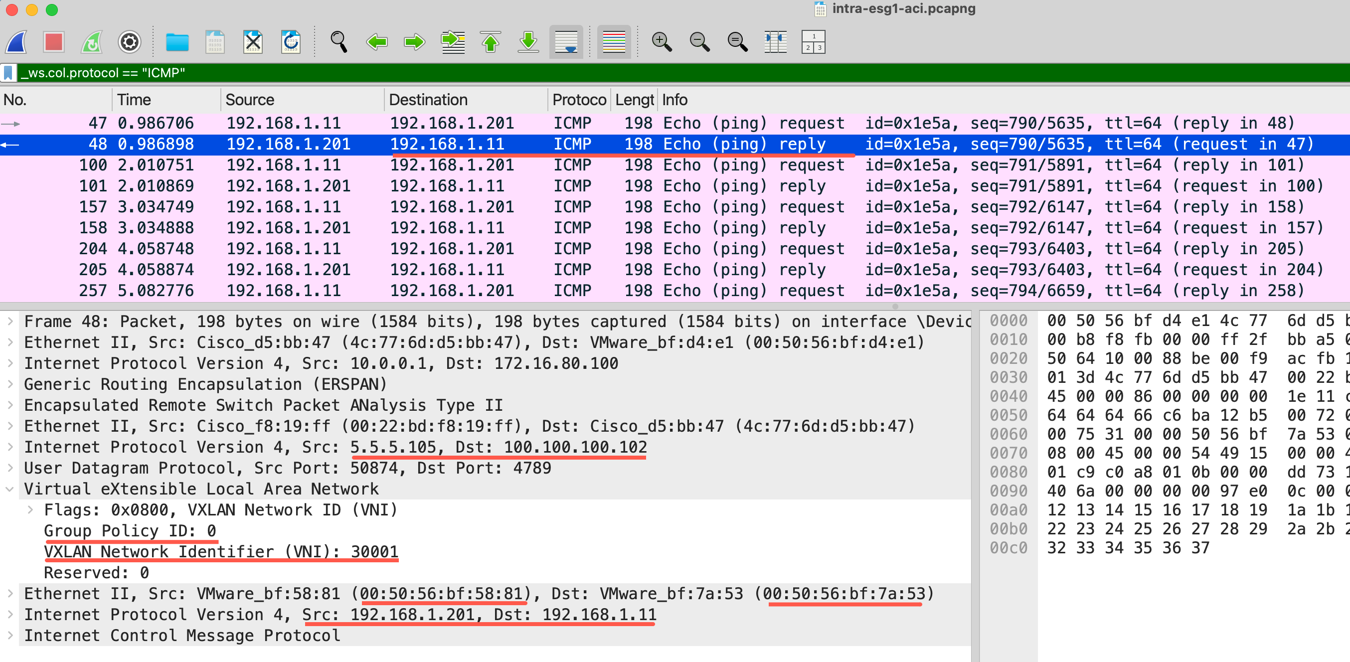
Figure 112. Intra-Subnet communication policy enforcement
For Layer 2 communication, policy enforcement occurs on the compute leaf where the traffic enters the ACI fabric. This is possible because the compute leaf has learned the remote endpoint MAC address, along with the associated pcTag, through data-plane activity. If the compute leaf has not learned the required MAC endpoint information, the Border Gateway performs policy enforcement instead. Since the traffic is bridged within the same Layer 2 domain, ACI performs the policy based on the source and destination MAC addresses.
● Source site: If the destination endpoint MAC is learned, the compute leaf applies policy, else the Border Gateway applies policy.
● Destination site: The compute leaf applies policy.
Use Case 2: Inter-Subnet Communication with Stretched BDs and Multiple ESGs
The figure below illustrates the logical design. In this use case, the source and the destination endpoints are in the different stretched BD subnets and are classified to different ESGs.
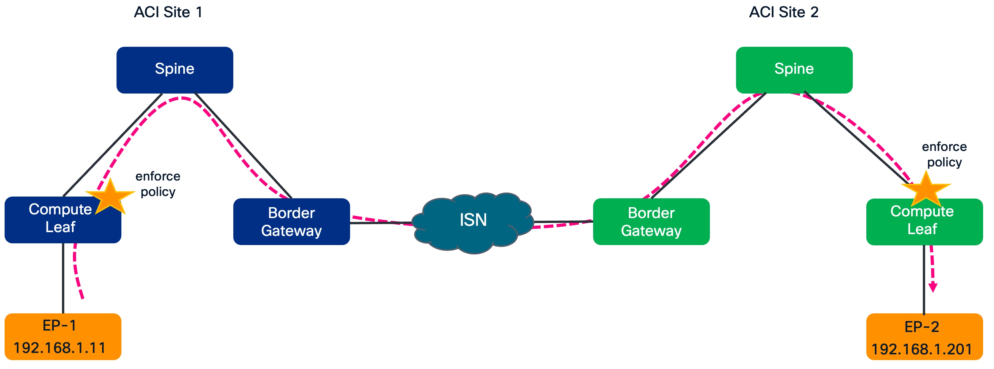
Figure 122. Inter-Subnet Communication
It is assumed that the baseline tenant configuration has already been completed, including the creation of tenants, VRFs, BDs, application profiles, and EPGs, as well as the stretching of VRFs and BDs. It is also assumed that you are already familiar with the process of migrating an EPG to an ESG and configuring a normalized pcTag for an ESG. The following screenshot shows the completed configuration for esg2.
ESG esg2 uses EPG epg1 as EPG selector.
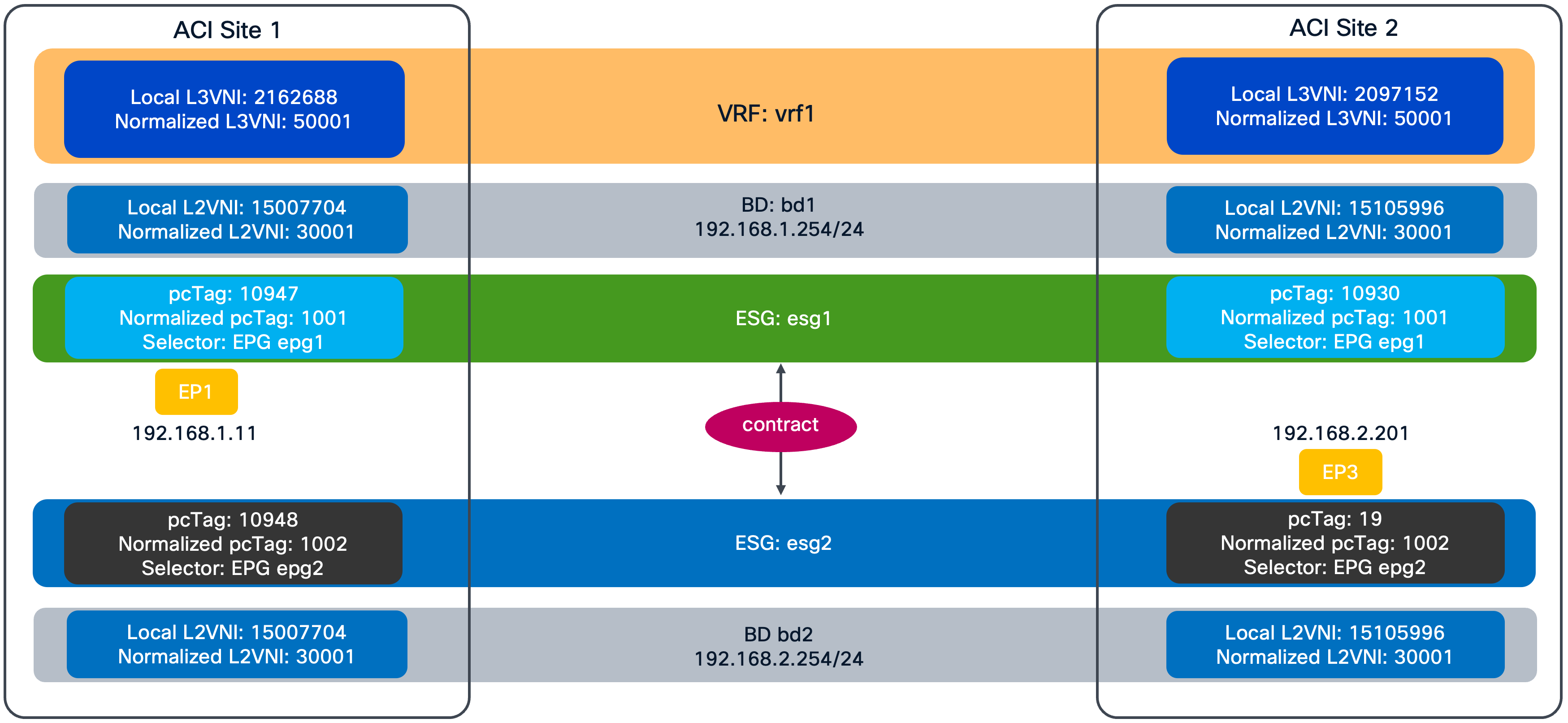
Figure 123. ACI Site 1 esg2
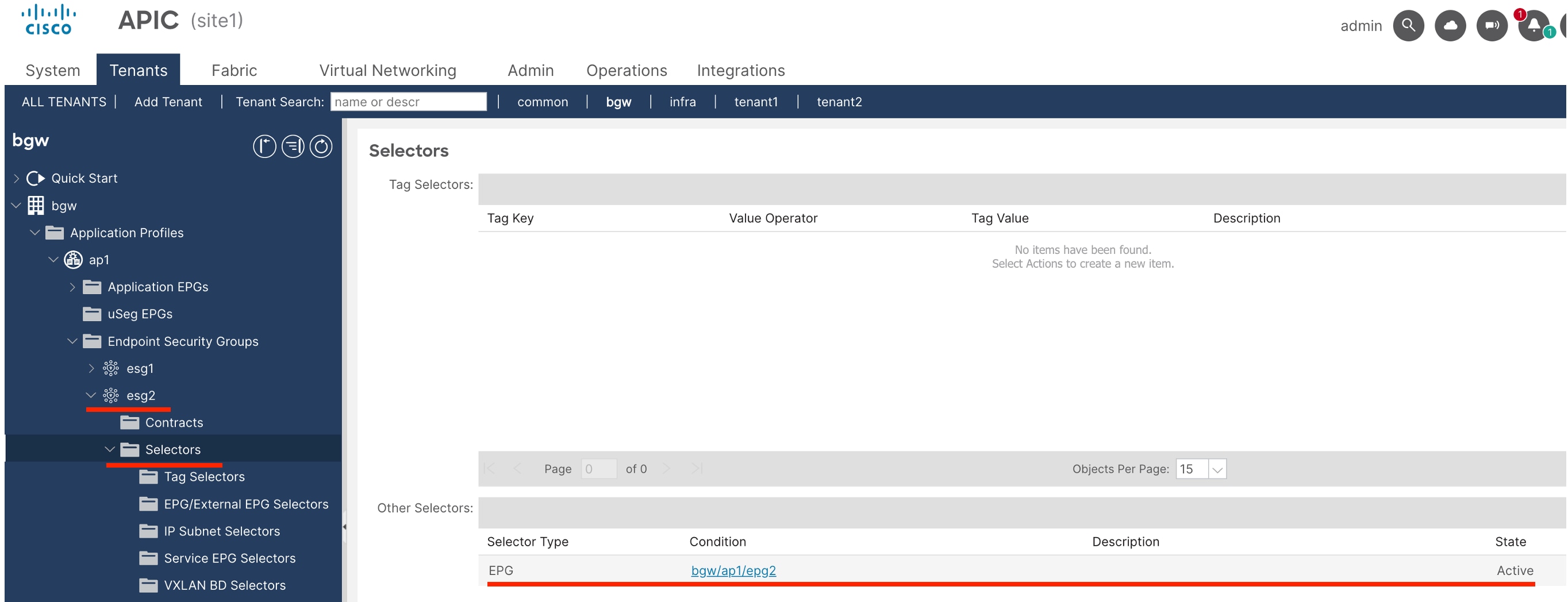
Figure 124. ACI Site 1 esg2 normalized pcTag
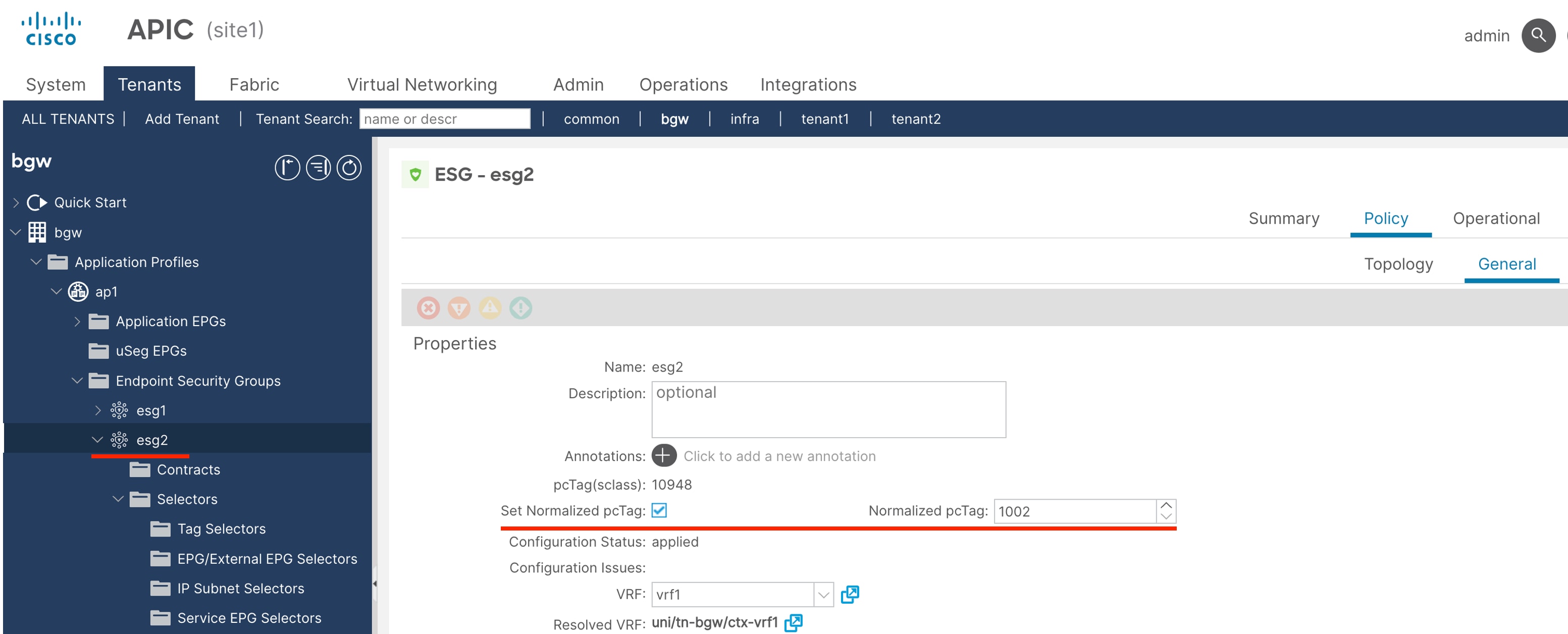
Figure 125. ACI Site 1 esg2 endpoints
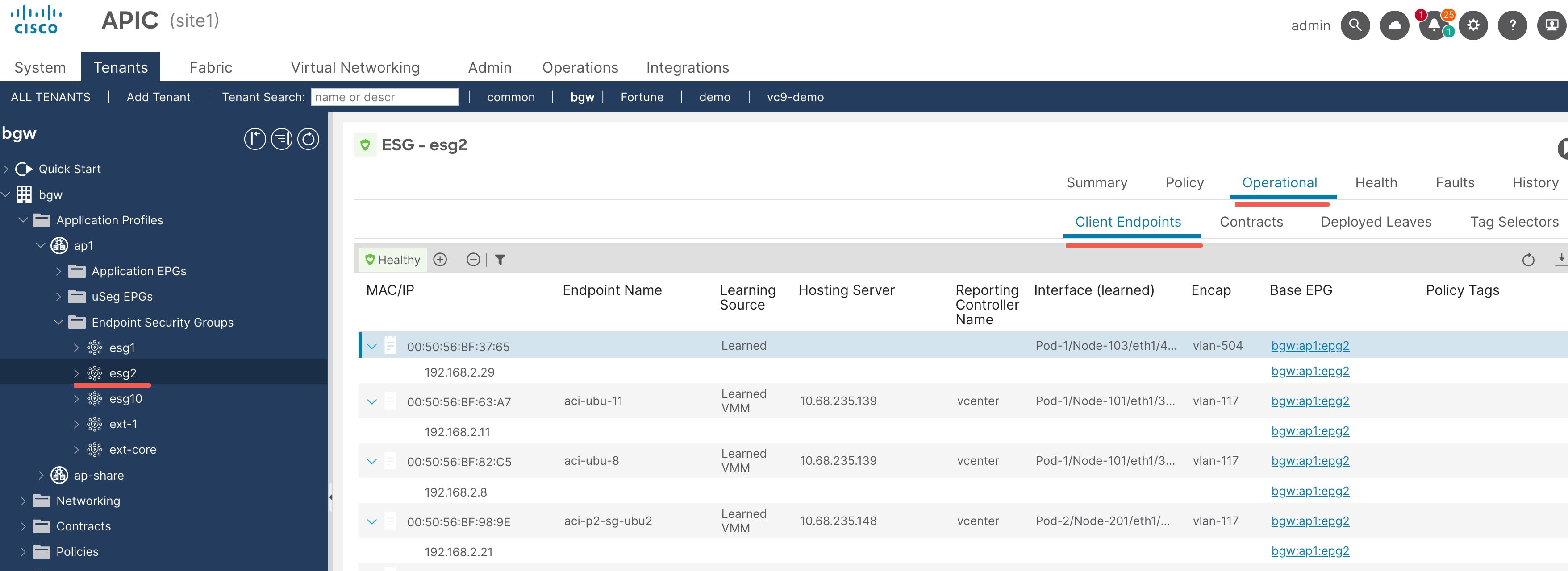
Figure 126. ACI Site 2 esg2
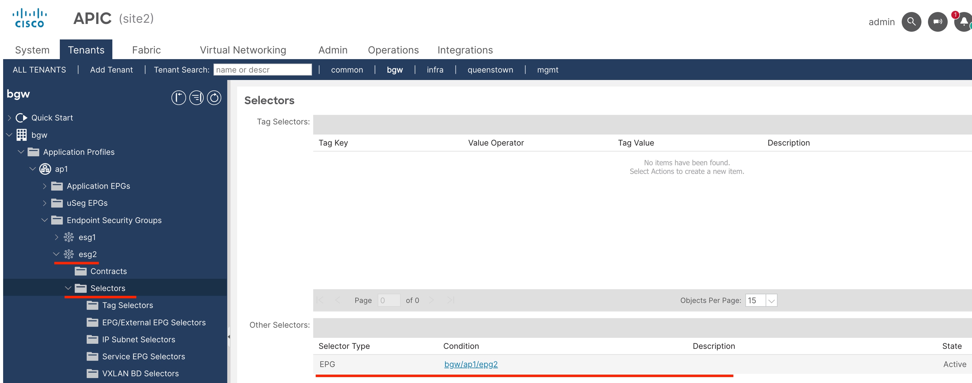
Figure 127. ACI Site 2 esg2 normalized pcTag
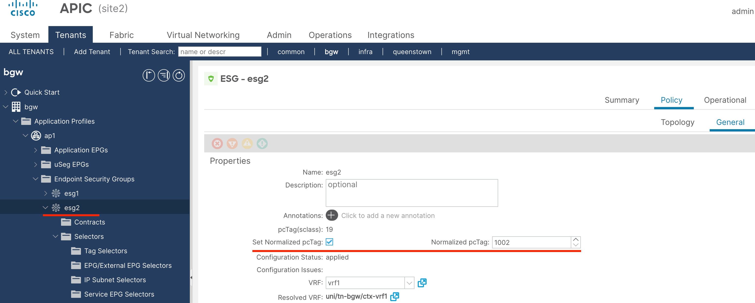
Figure 128. ACI Site 2 esg2 endpoints
Since the endpoints in BD1 and BD2 are classified into different ESGs, a contract is required to enable communication between them. In this example, esg1 is the consumer and esg2 is the provider. The policy must be configured consistently across both APIC domains to ensure the intended communication behavior. Nexus Dashboard could help address this operational challenge in a future release by providing a centralized point for policy authoring.
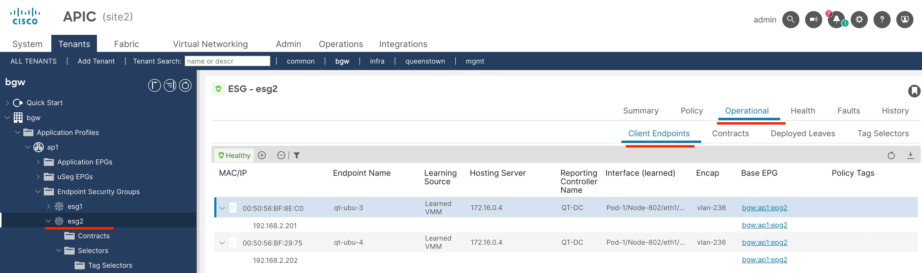
Figure 129. ACI Site 1 esg1 contract consumer
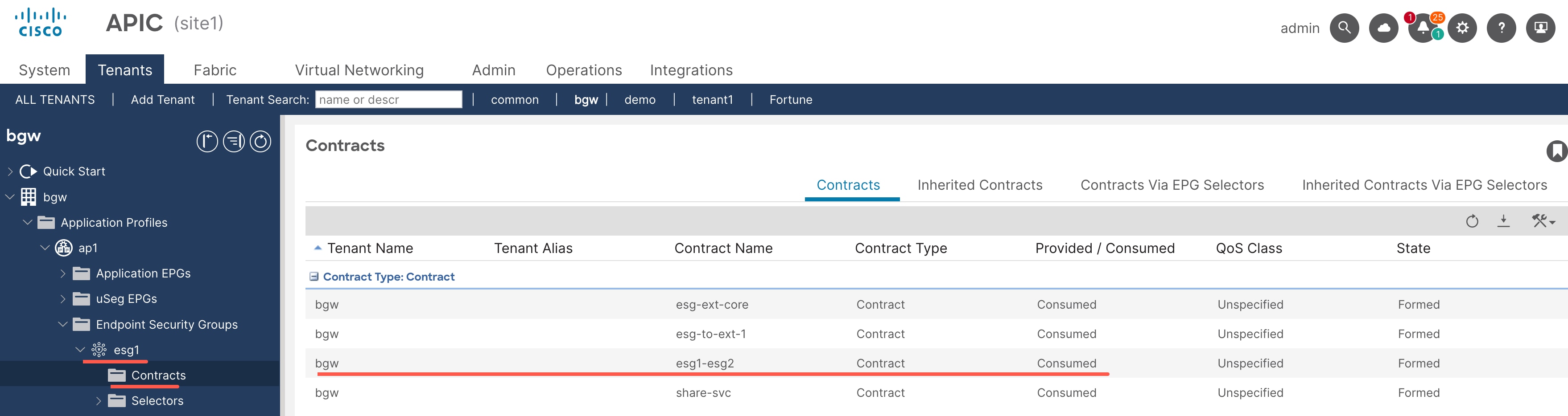
Figure 130. ACI Site 1 esg1 contract provider
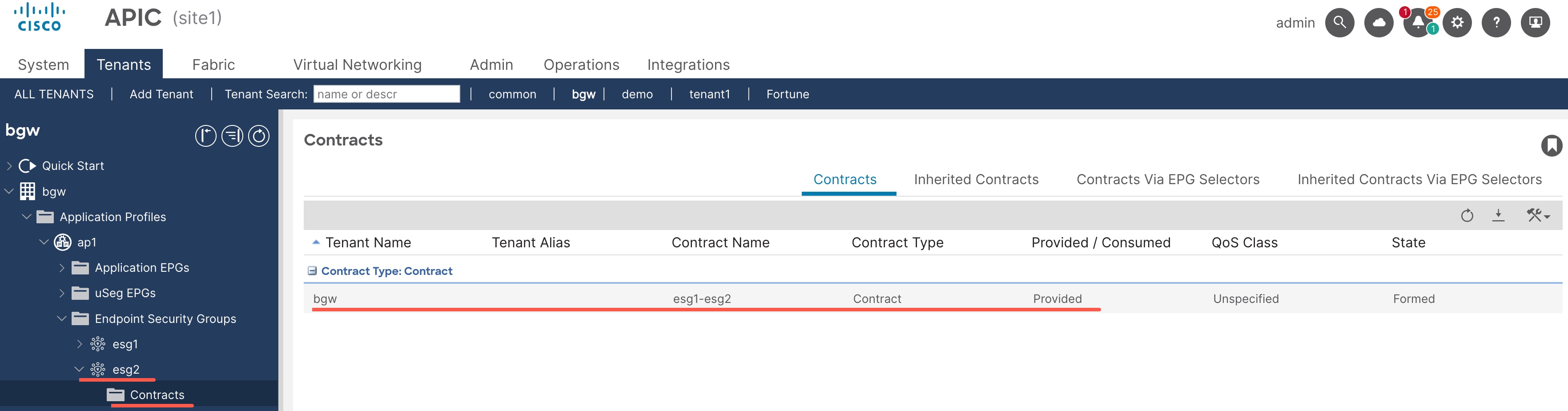
Figure 131. ACI Site 2 esg1 contract consumer
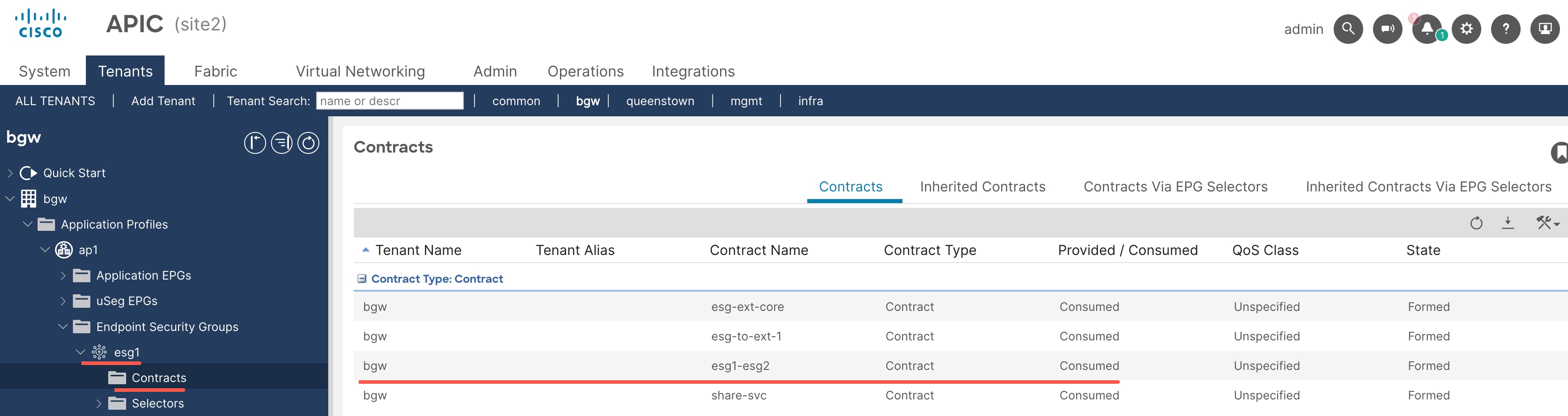
Figure 132. ACI Site 2 esg2 contract provider
Control Plane Verification
Control plane verification is very similar to intra-subnet communication in the previous section. Border Gateway in ACI Site 1 learns endpoint information of endpoints in esg2 in ACI Site 2. Endpoints information includes MAC address and IP address since BD2 also has Unicast routing on. Below are few screenshots for illustration purpose, the similar information could be seen on ACI Site 2.
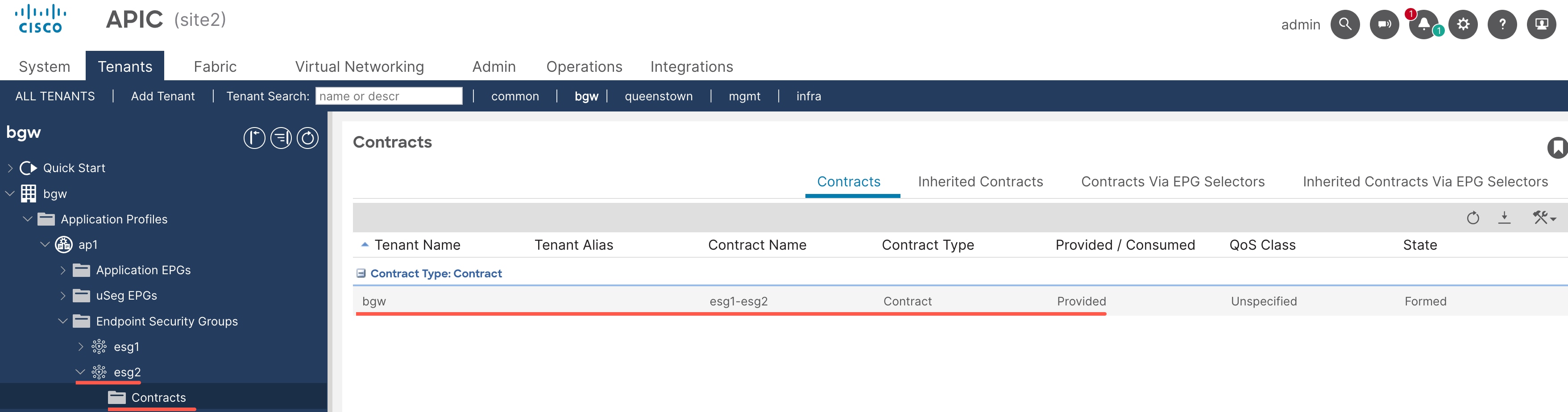
Figure 133. ACI Site 1 Border Gateway learns MAC endpoint from ACI Site 2
Although the endpoint is in ACI Site 2 and is associated with a different pcTag in that site, the border gateway in ACI Site 1 learns the endpoint with the local pcTag of esg2 in ACI Site 1, which is 10948.
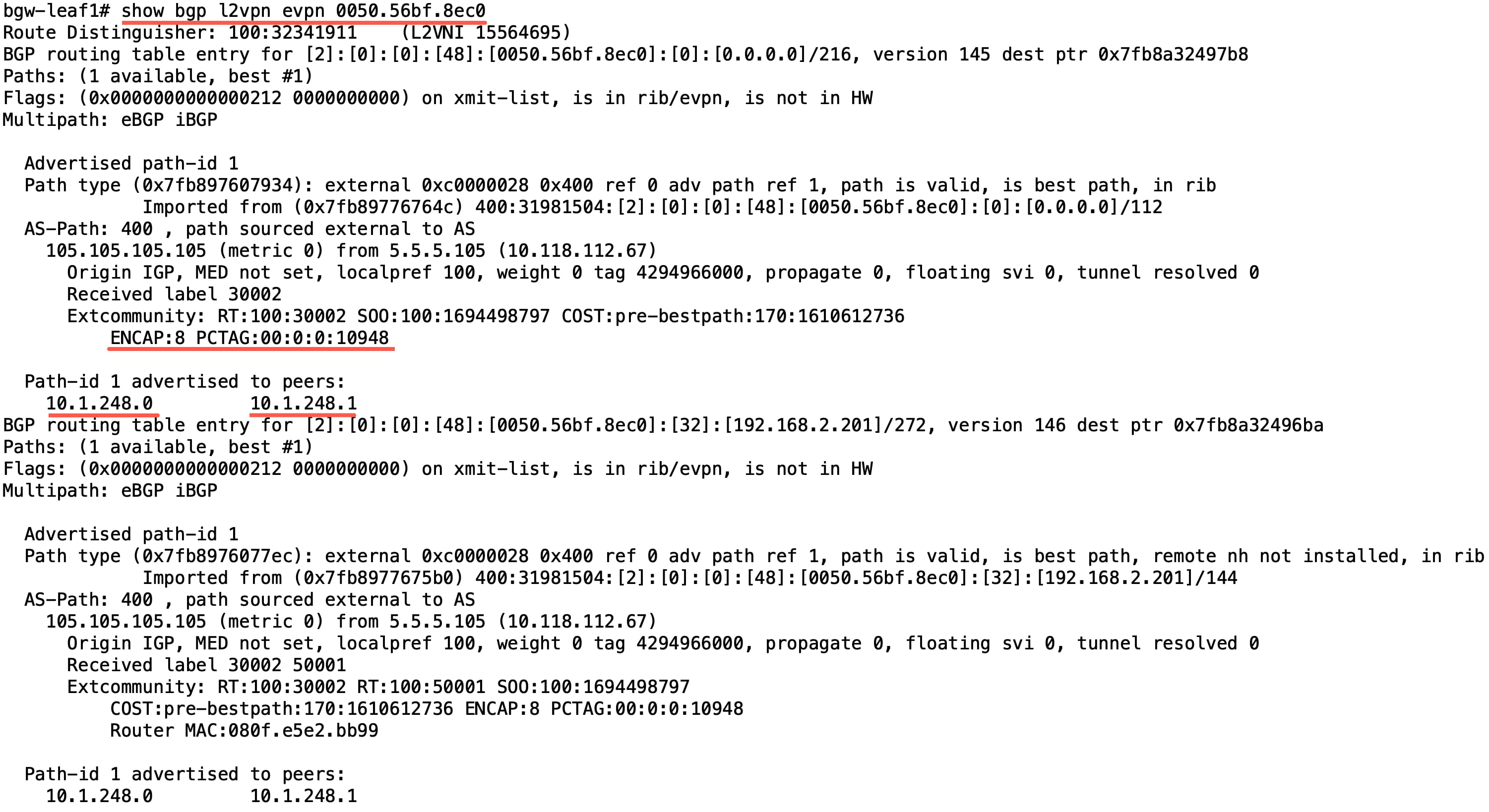
Figure 134. ACI Site 1 Border Gateway learns IP endpoint from ACI Site 2
Data Plane Verification
Communication happens between two endpoints EP-1 and EP-3 across sites. Normalized VNI 50001 is defined by administrator by configuring the normalized VRF VNI when stretching VRF across two sites.
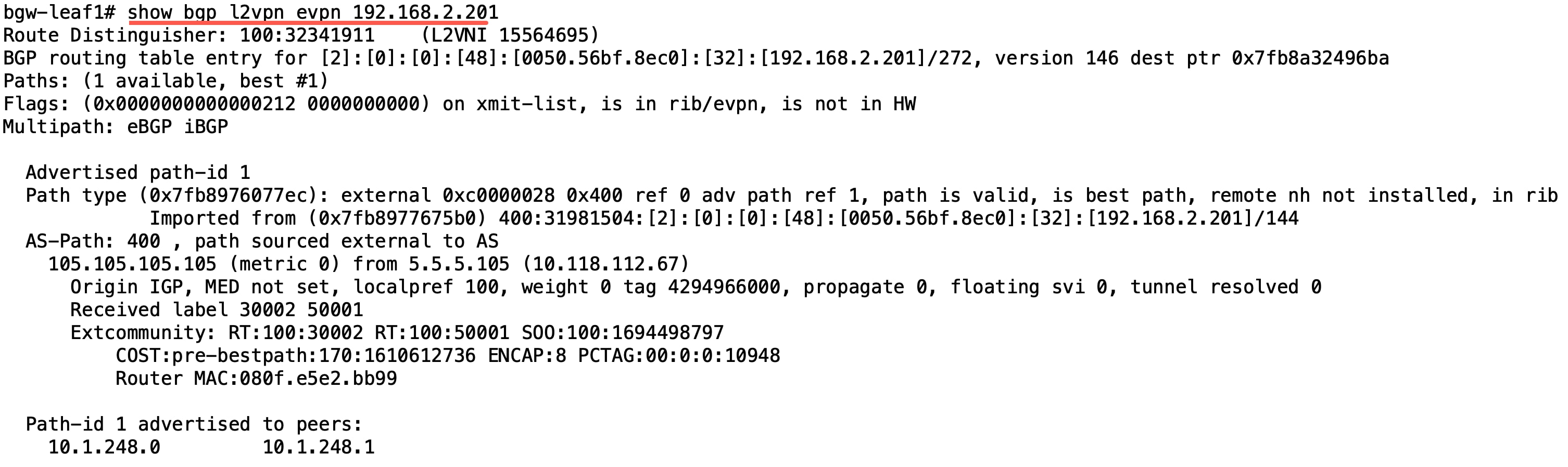
Figure 135. Data plane Routed Communication across sites
The following packet capture was obtained via ERSPAN traffic from ISN device. The packet capture of the ICMP request from EP-1 to EP-3 confirms that the Layer 3 (VRF) Normalized VNI is used in the VXLAN header for inter-site data plane forwarding.
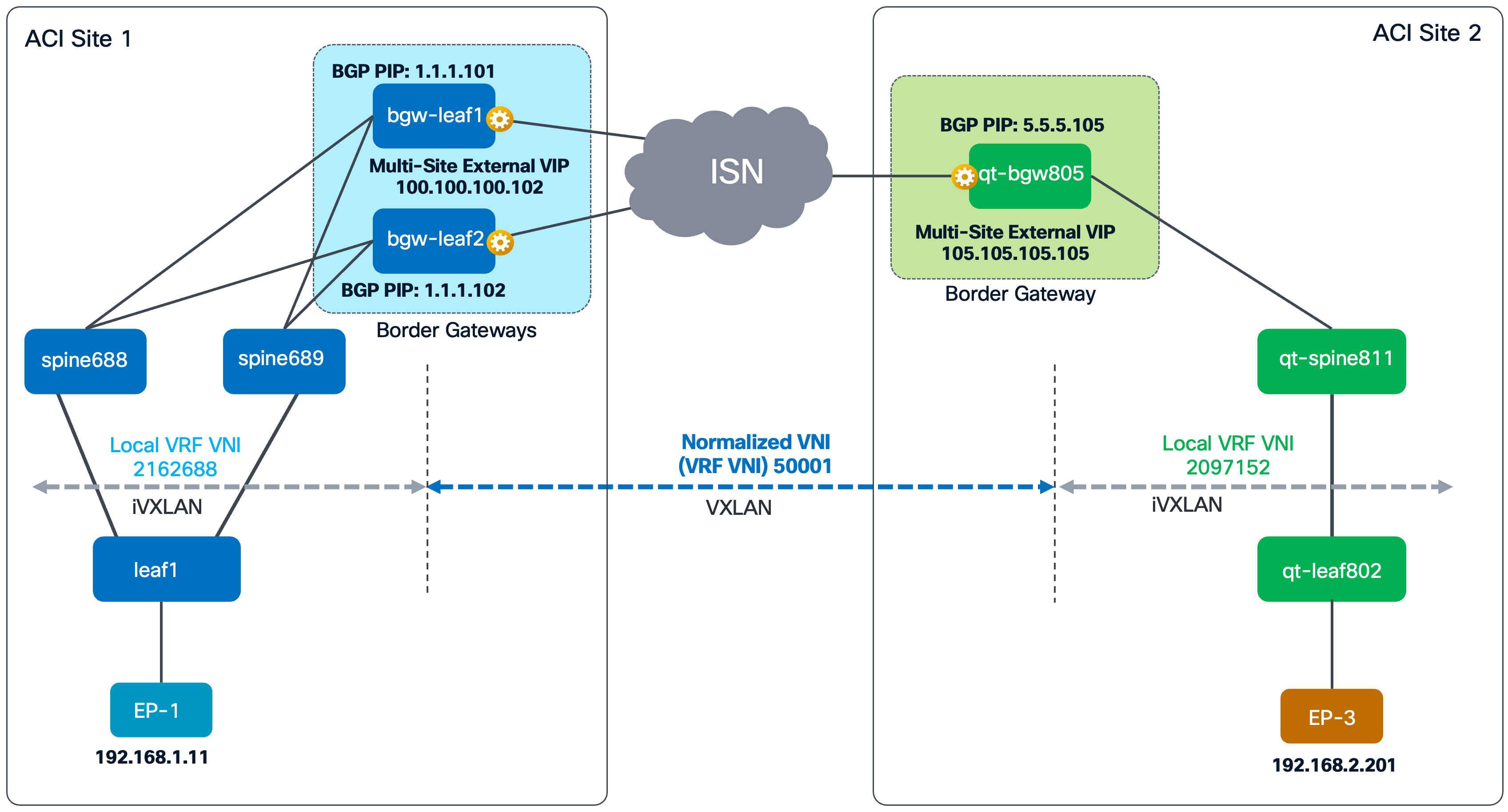
Figure 138. ICMP request from EP-1 (192.168.1.11) to EP-3 (192.168.2.201)
The packet capture of the ICMP reply from EP-3 to EP-1 confirms that the Layer 3 (VRF) Normalized VNI is used in the VXLAN header for inter-site data plane forwarding.
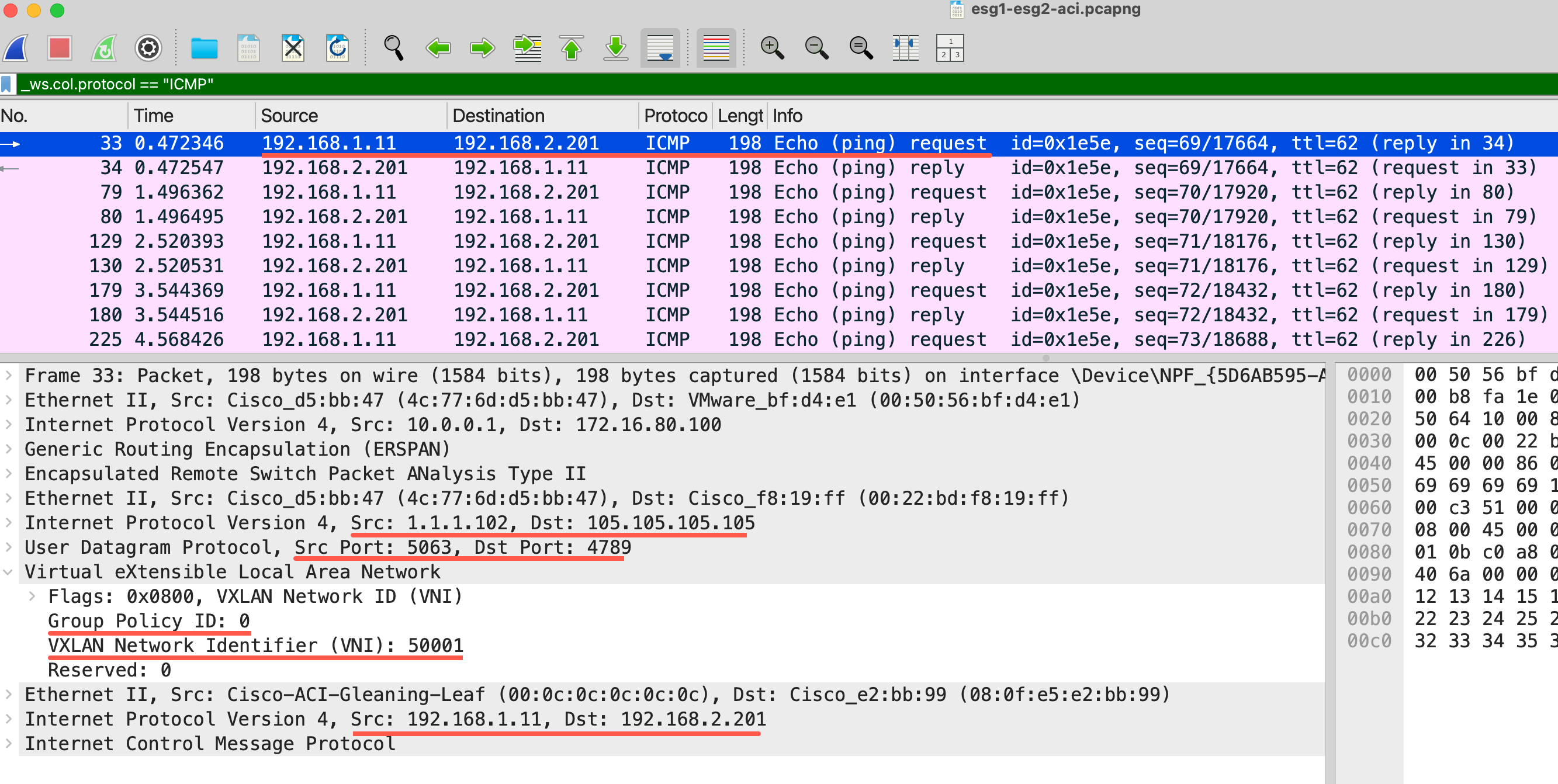
Figure 139. ICMP reply from EP-3 (192.168.2.201) to EP-1 (192.168.1.11)
The figure below illustrates the policy enforcement locations for inter-subnet communication.
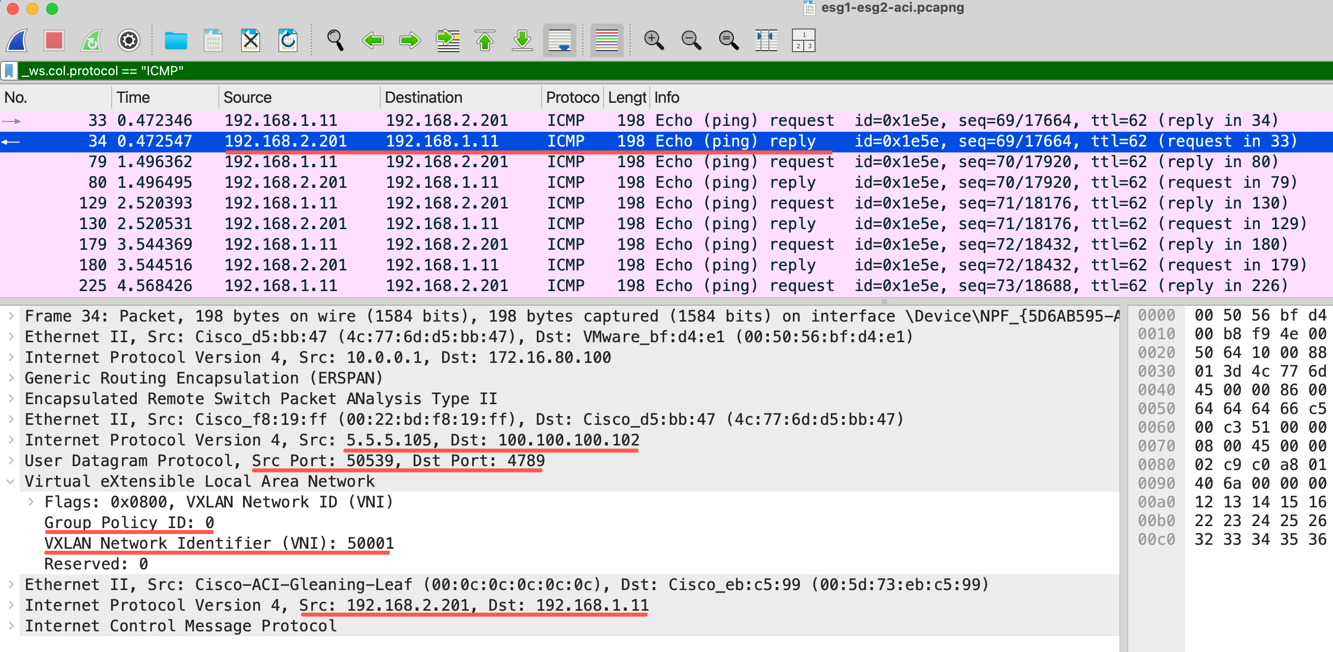
Figure 140. Inter-subnet communication policy enforcement Site 1 to Site 2
Traffic from ACI Site 1 to ACI Site 2: The ACI Site 1 Border Gateway and the ACI Site 2 compute leaf enforce policy for this traffic flow. From the ACI Site 1 perspective, the destination endpoint in ACI Site 2 is a remote endpoint. The remote endpoint information is advertised to the ACI Site 1 Border Gateway and then advertised to the ACI Site 1 spines through EVPN. The endpoint information is subsequently stored in the spine COOP database. This information is not advertised to the ACI Site 1 compute leaf, which is consistent with the standard ACI COOP behavior designed to conserve hardware resources on the compute leaf. At the same time, the remote endpoint IP is not learned on the compute leaf, even based on received data plane traffic. This is because the local Border Gateway sets the Do-Not-Learn bit to the traffic received from remote site that is re-encapsulated toward to the local compute leaf. The ACI Site 1 Border Gateway has the required remote endpoint classification context and performs policy enforcement for traffic leaving the site. In ACI Site 2, although Border Gateway has endpoint information advertised by a local spine, it does not program the information to local hardware table for scalability reason, the compute leaf attached to the destination endpoint enforces policy based on the locally learned endpoint information.
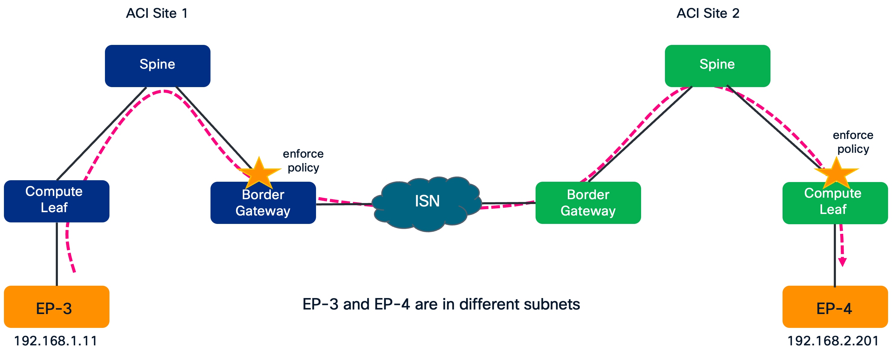
Figure 141. Inter-subnet communication policy enforcement Site 2 to Site 1
Traffic from ACI Site 2 to ACI Site 1: The same logic applies to the reverse direction. The ACI Site 2 Border Gateway enforces policy for traffic leaving the site, whereas the ACI Site 1 compute leaf enforces the policy for traffic destined to the locally attached endpoint.
Use Case 3: Inter-Subnet Communication with Non-stretched BDs and Single ESG
This use case describes communication between endpoints residing in different subnets. It differs from Use Case 2, in which the BDs are deployed locally on each site and a single ESG is used to classify endpoints part of both subnets. Because the endpoints belong to the same ESG, they can communicate without a contract and for that to work the ESG normalized pcTag must be identical on both sites. The following diagram illustrates this scenario.
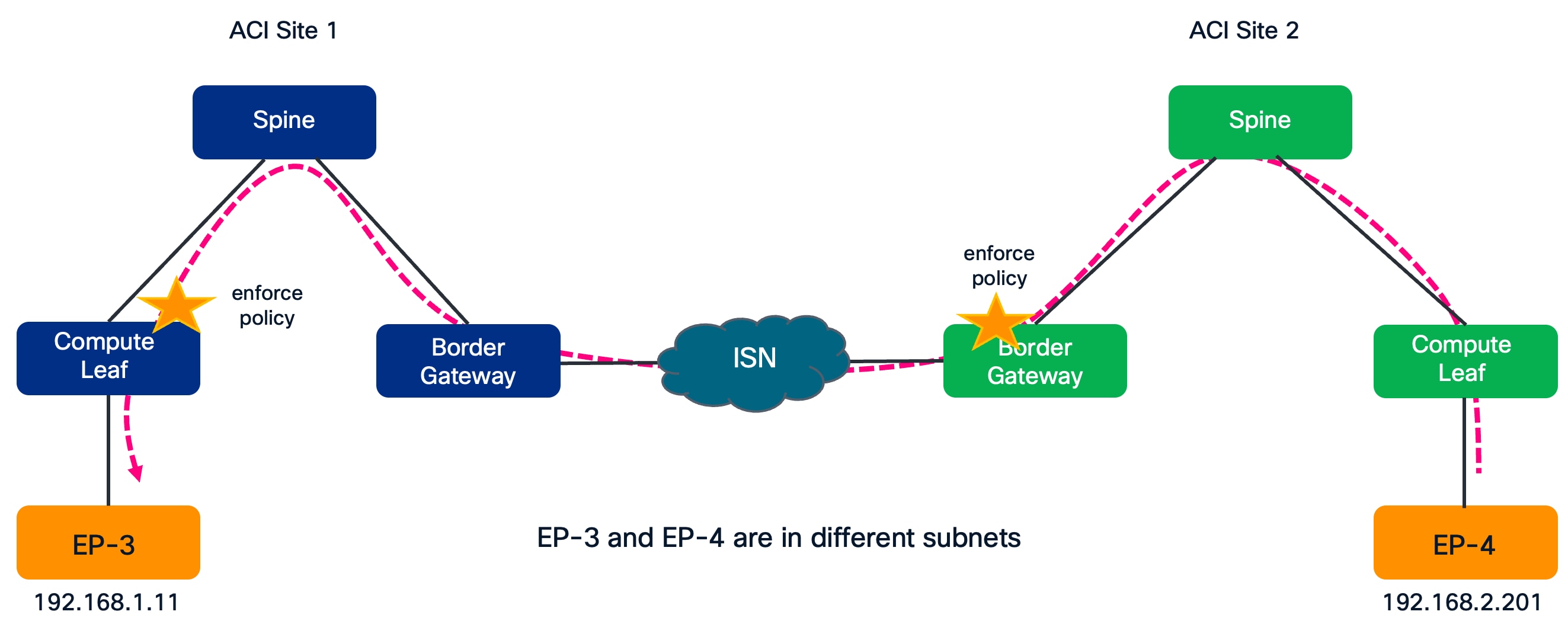
Figure 149. Inter-Subnet Communication Non-Stretched BDs Single ESG
As shown in the above diagram, bd10 is deployed locally in ACI Site 1, and bd20 is deployed locally in ACI Site 2. The ESG esg1020 is stretched across the two ACI sites; however, its selectors differ between the sites. At a high level, the following are the main configuration steps, assuming that VRF vrf1 has already been deployed and stretched across the sites.
● On ACI Site 1, create bd10 with the subnet defined with “Advertised Externally” scope enabled.
● On ACI Site 1, deploy bd10 to Border Gateway by associating the BD to the Border Gateway Set.
● Create epg10 in bd10, create esg1020 and use EPG selector epg10, use 1020 as Normalized pcTag.
● On ACI Site 2, create bd20 with the subnet defined with “Advertised Externally” scope enabled.
● On ACI Site 2, deploy bd20 to Border Gateway by associating the BD to the Border Gateway Set.
● Create epg20 in bd20, create esg1020 and use EPG selector epg20, use 1020 as Normalized pcTag.
After the above steps are completed, the EVPN Type-5 route is exchanged between the two sites. In addition, because the BDs are deployed on the Border Gateway, the EVPN Type-2 route carrying the pcTag is also exchanged across sites. As a result, endpoint EP1 in bd10 in ACI Site 1 can communicate with endpoint EP2 in bd20 in ACI Site 2. The next section covers configuration result and verification.
Create non-stretched local Bridge Domain and ESG
On ACI Site 1 create Bridge Domain bd10:
● L2 Unknown Unicast: Flood
● L3 Configurations: Unicast Routing (checked)
◦ Subnet 192.168.10.254/24 has scope Advertised Externally
The “Advertised Externally” scope must be enabled to allow subnet advertisement (EVPN type-5 routes) to remote ACI sites.
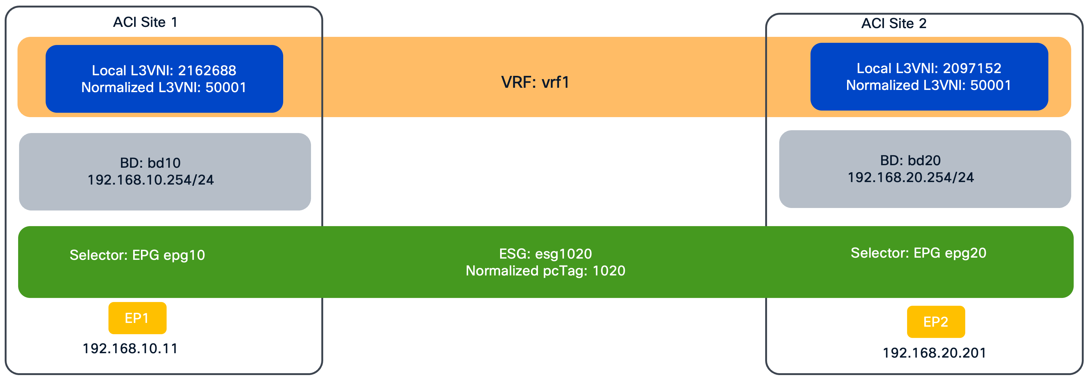
Figure 150. ACI Site 1 bd10 L2 Unknown Unicast Flood
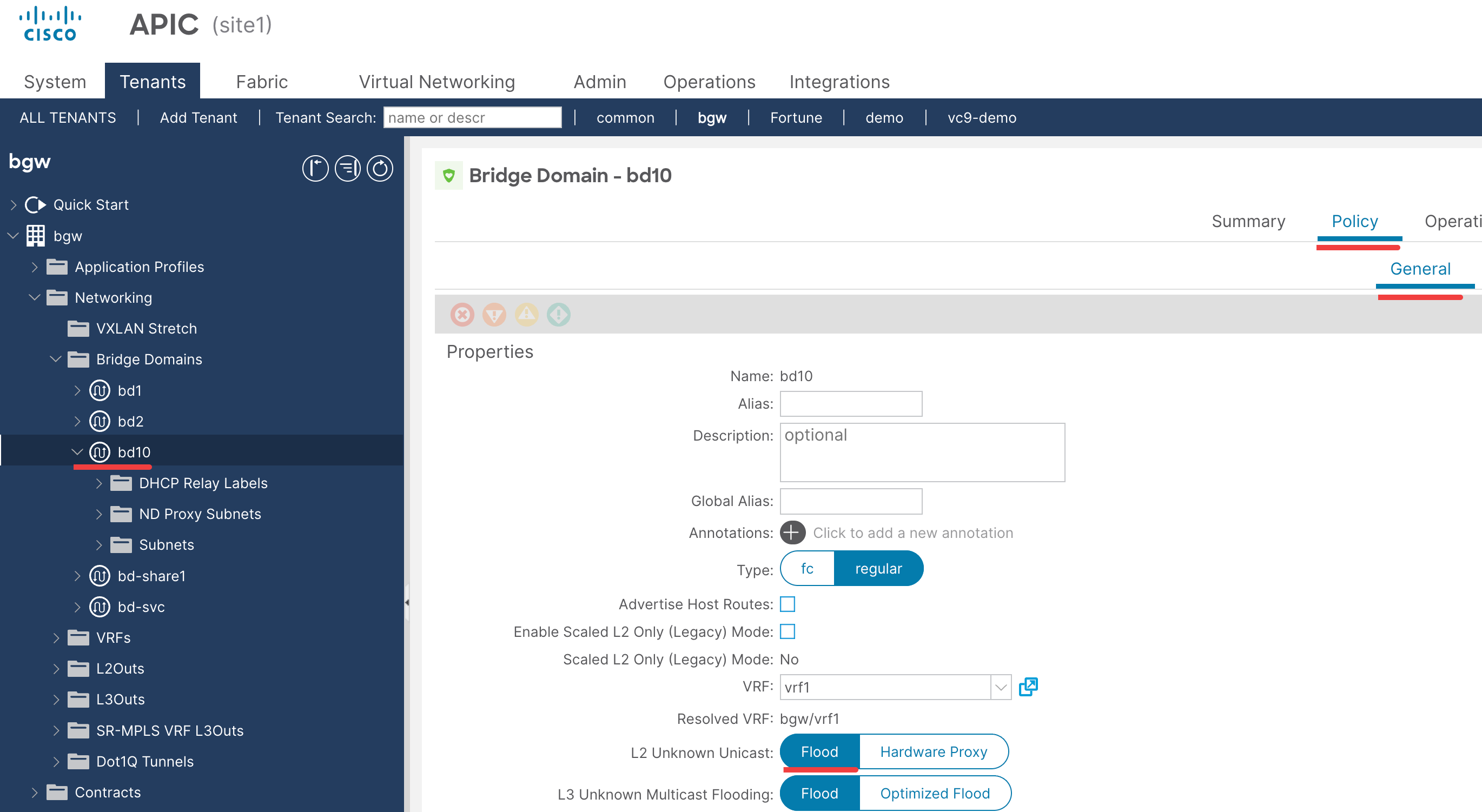
Figure 151. ACI Site 1 bd10 L3 Configurations
Deploy BD bd10 and associate it with the Border Gateway. This association is required even when the subnet remains local to the site, because it enables the Border Gateway to advertise EVPN Type-2 endpoint routes carrying pcTag information to the remote site. The remote site uses this pcTag information for endpoint classification and policy enforcement. A BD is considered local to a site when its Normalized VNI is unique across multiple ACI sites (independently from the name assigned to the BD). In this example, Normalized VNI 30010 is assigned to bd10. Conversely, in ACI Site 2, Normalized VNI 30020 is assigned to bd20.
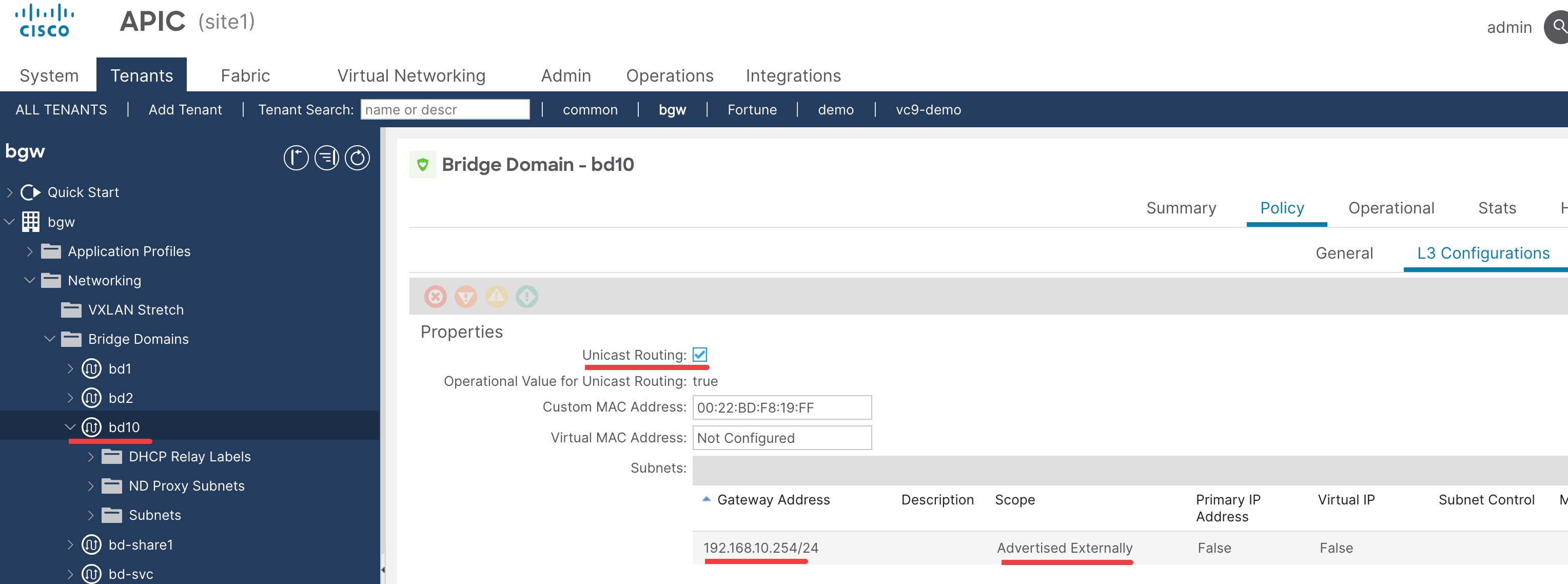
Figure 152. ACI Site 1 deploy bd10 on border gateway
The subsequent step is to create the ESG esg1020. Consistent with the preceding procedures, the associated EPG must be defined prior to the creation of the ESG.
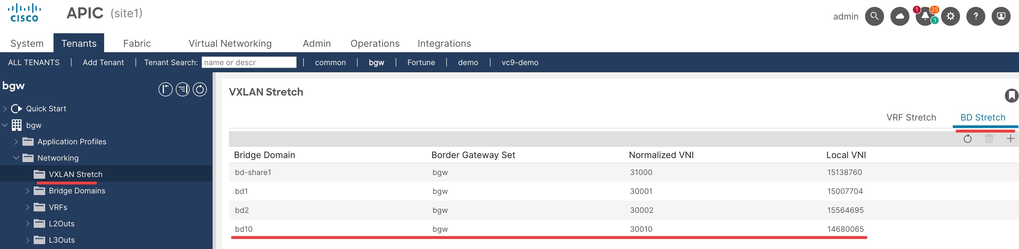
Figure 153. ACI Site 1 epg10
ESG esg1020 uses EPG epg10 as EPG selector.
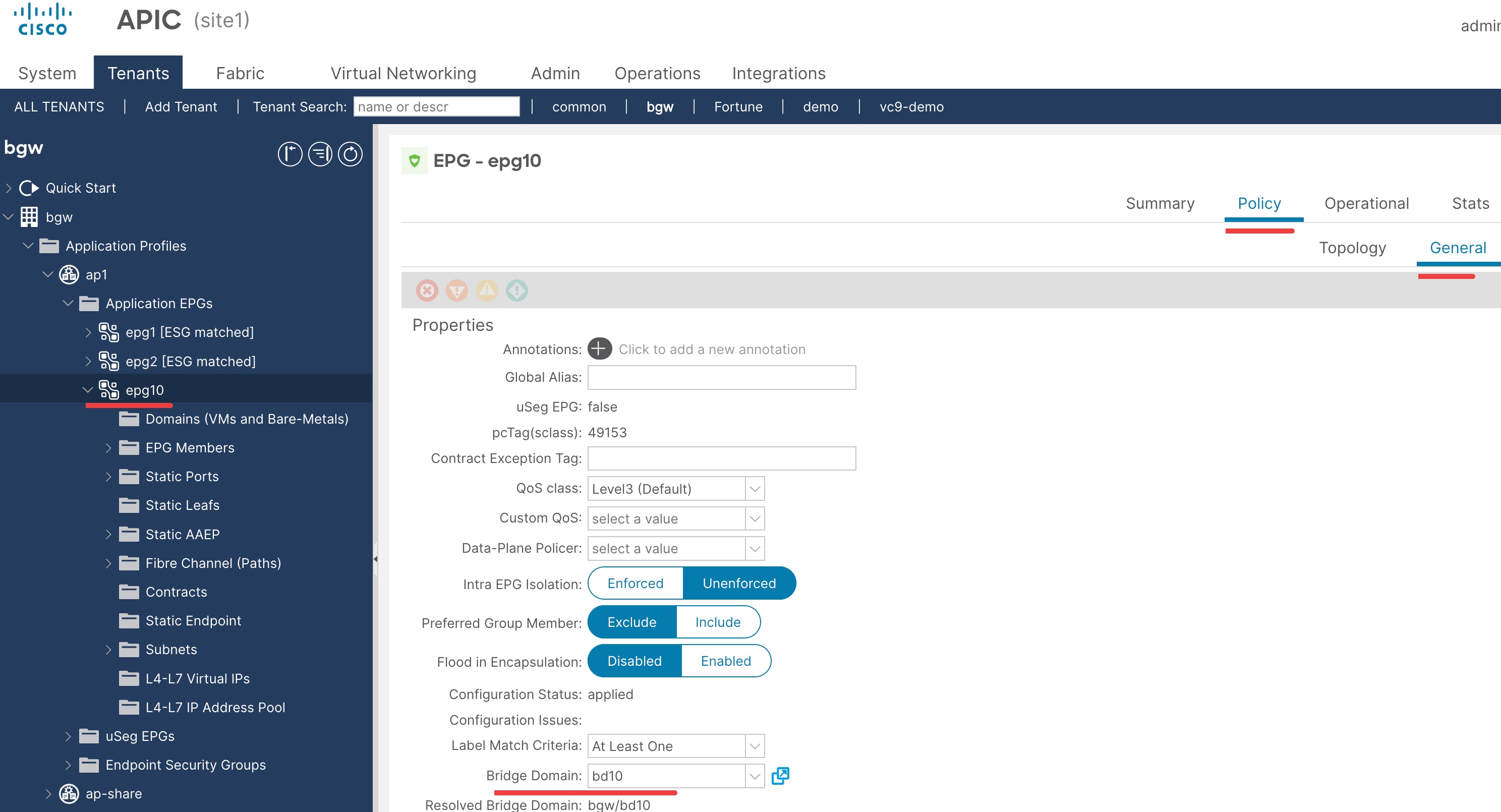
Figure 154. ACI Site 1 esg1020 EPG selector
Set the Normalized pcTag to 1020 for ESG esg1020.
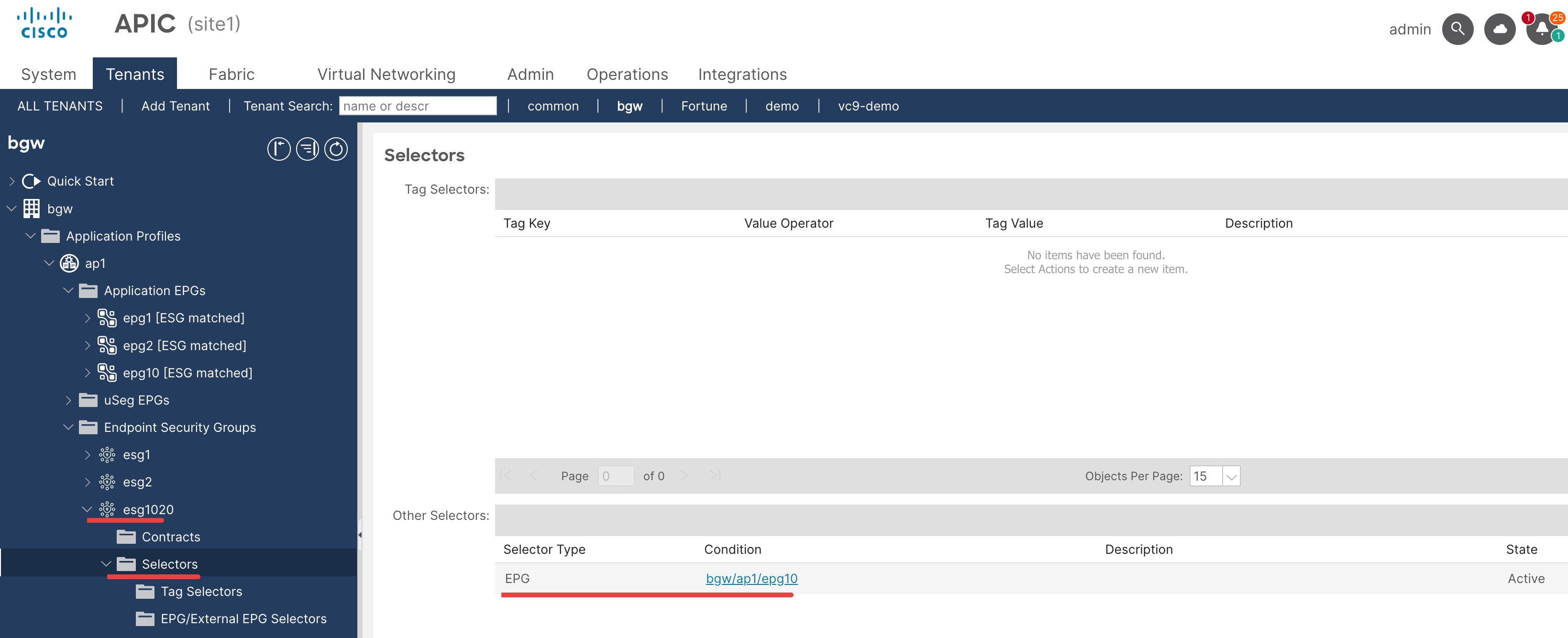
Figure 155. ACI Site 1 esg1020 Normalized pcTag
On ACI Site 2 create Bridge Domain bd20:
● L2 Unknown Unicast: Flood
● L3 Configurations: Unicast Routing (checked)
◦ Subnet 192.168.20.254/24 has scope Advertised Externally
The “Advertised Externally” scope must be enabled to allow subnet advertisement to remote ACI sites.
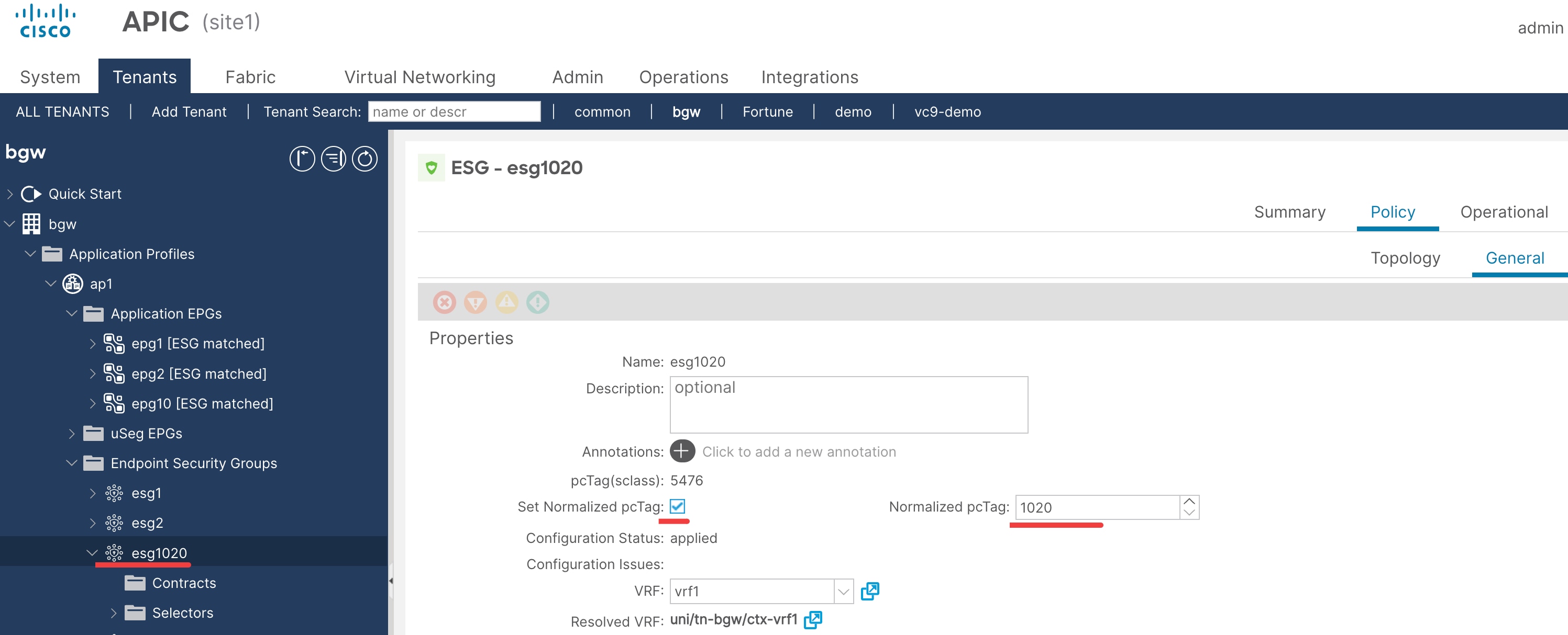
Figure 156. ACI Site 2 bd20 L2 Unknown Unicast Flood
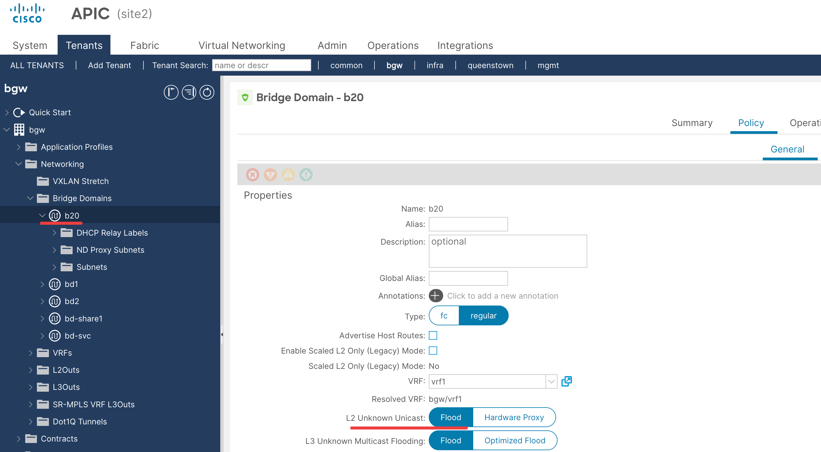
Figure 157. ACI Site 2 bd20 L3 Configurations
Deploy BD bd20 by associating it with the Border Gateway. In this example, the Normalized VNI 30020 is distinct from the VNI 30010 assigned to bd10 on ACI Site 1. This distinction indicates that bd10 on ACI Site 1 and bd20 on ACI Site 2 are independent, non-stretched entities, each deployed locally on its respective site Border Gateway to advertise EVPN Type-2 route.
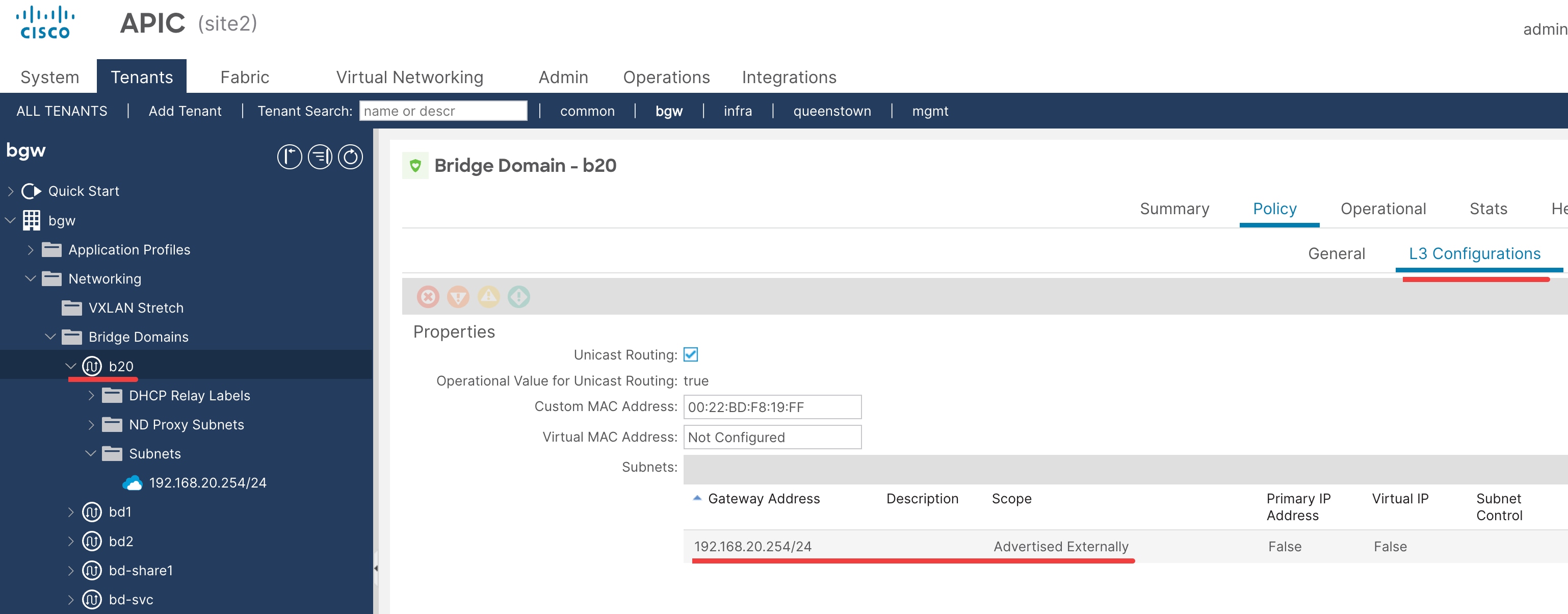
Figure 158. ACI Site 2 deploy bd20 on Border Gateway
The subsequent step is to create ESG esg1020. Consistent with the preceding procedures, the associated EPG must be defined prior to the creation of the ESG.
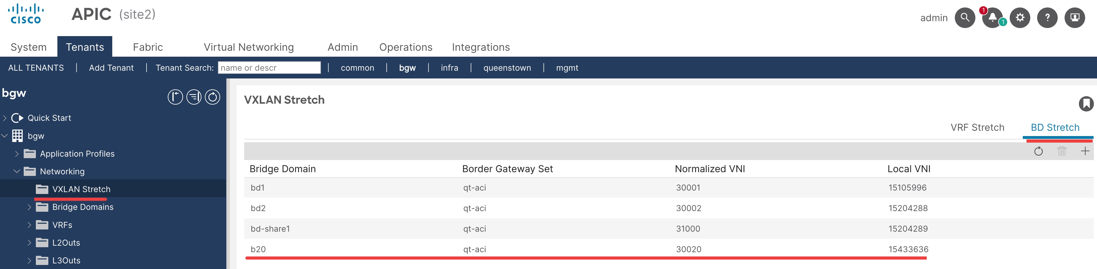
Figure 159. ACI Site 2 epg20
Create ESG esg1020 using EPG epg20 as EPG Selector.
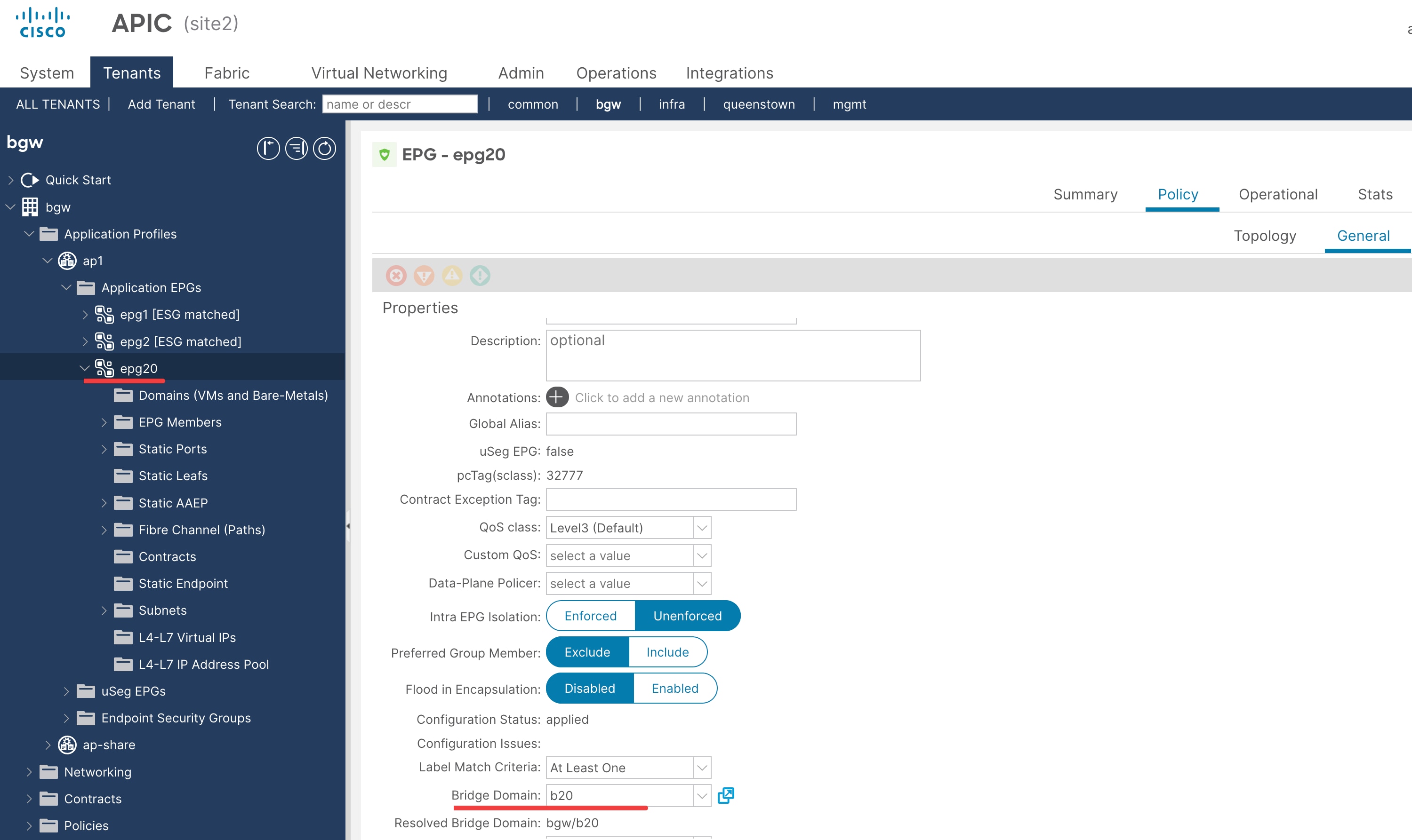
Figure 160. ACI Site 2 esg1020 EPG selector
Set the Normalized pcTag to 1020 for ESG esg1020.
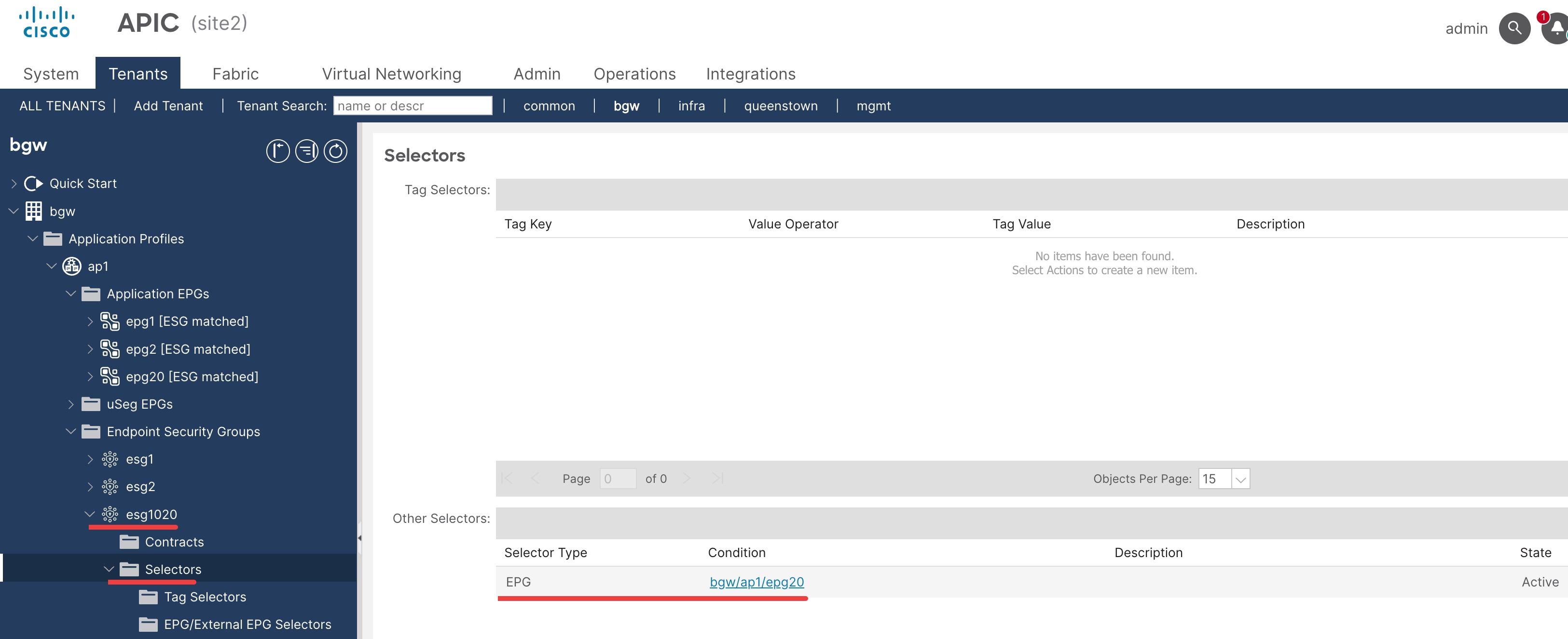
Figure 161. ACI Site 2 esg1020 Normalized pcTag
Control Plane Verification
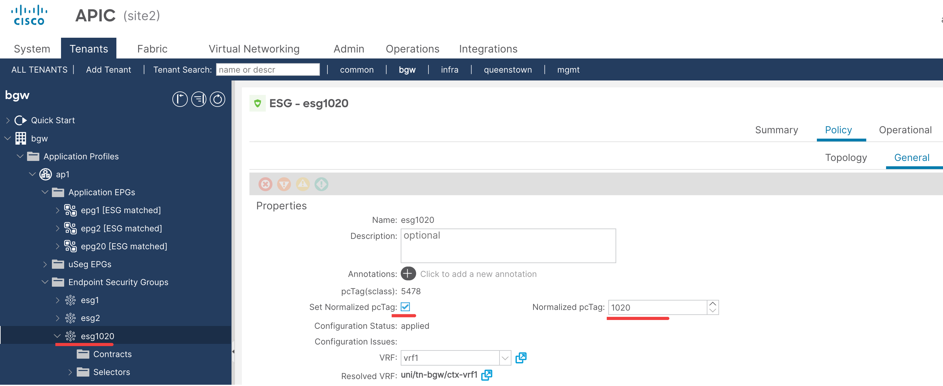
Figure 162. ESG esg1020
The control-plane verification for this use case follows the same general approach as the previous use case, “Use Case 2: Inter-Subnet Communication with Stretched BDs and Multiple ESGs”. The key difference is that bd10 and bd20 are deployed locally in ACI Site 1 and ACI Site 2, respectively, rather than being configured as stretched BDs. As a result, the verification in this scenario should focus on both EVPN Type-5 and EVPN Type-2 route advertisements across the two sites.
Because the BDs are locally deployed, EVPN Type-5 routes are required to exchange subnet reachability information between the sites otherwise compute leaf in local site does not have route to the non-stretched (local) BD subnet defined in the remote site. In this example, IP subnet 192.168.10.0/24 must be advertised to ACI Site 2, and IP subnet 192.168.20.0/24 must be advertised to ACI Site 1.
In addition, EVPN Type-2 routes are required to exchange endpoint reachability information and support end-to-end communication across the two sites. EVPN Type-2 routes also carry the pcTag information needed for endpoint classification and policy enforcement. Without this Type-2 route exchange, pcTag information would not be shared across sites, and policy enforcement for inter-site traffic is not possible. In this example, IP host route 192.168.10.11/32 must be advertised to ACI Site 2, and IP host route 192.168.20.201/32 must be advertised to ACI Site 1. The EVPN Type-2 route also carries the endpoint pcTag information when the endpoint is advertised to the remote site.
The block diagram below illustrates the EVPN Type-5 advertisement workflow from ACI Site 1 to ACI Site 2. Note that if only EVPN Type-5 route exchange is required between the sites, the BD does not need to be deployed on the Border Gateway. However, deployment of the BD on the Border Gateway is required when EVPN Type-2 route exchange is needed for policy enforcement. The same procedure applies in the reverse direction, from ACI Site 2 to ACI Site 1.
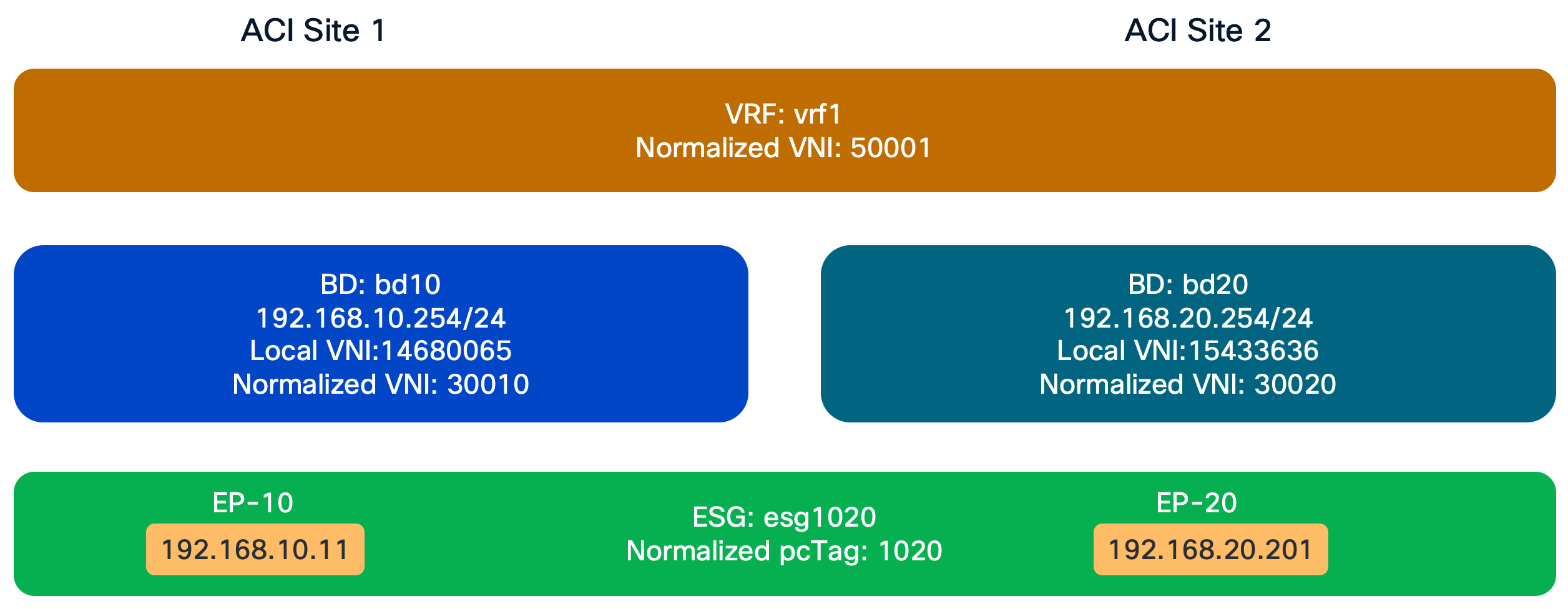
Figure 163. BGP EVPN Type-5 from Site 1 to Site 2
The next screenshots focus on the first Border Gateway in ACI Site 1, keep in mind that all Border Gateways in ACI Site 1 require the same procedure to advertise route to ACI Site 2.
ACI Site 1 Border Gateway has bd10 subnet 192.168.10.0/24 locally:
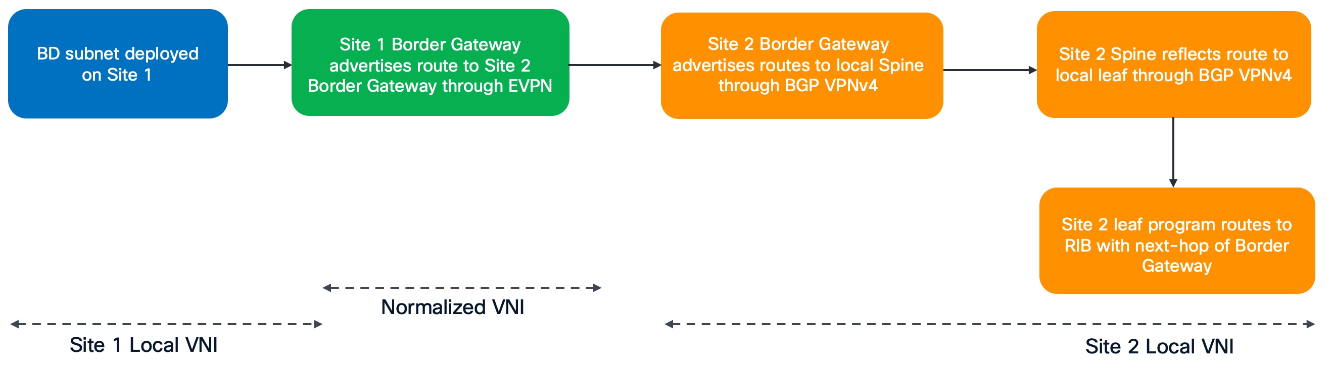
Figure 164. ACI Site 1 Border Gateway non-stretched (local) BD subnet
Non-stretched (local) BD subnet 192.168.10.0/24 is advertised by ACI Site 1 Border Gateways to ACI Site 2 Border Gateways through BGP EVPN. The IP 5.5.5.105 is loopback0 address of ACI Site 2 Border Gateway.
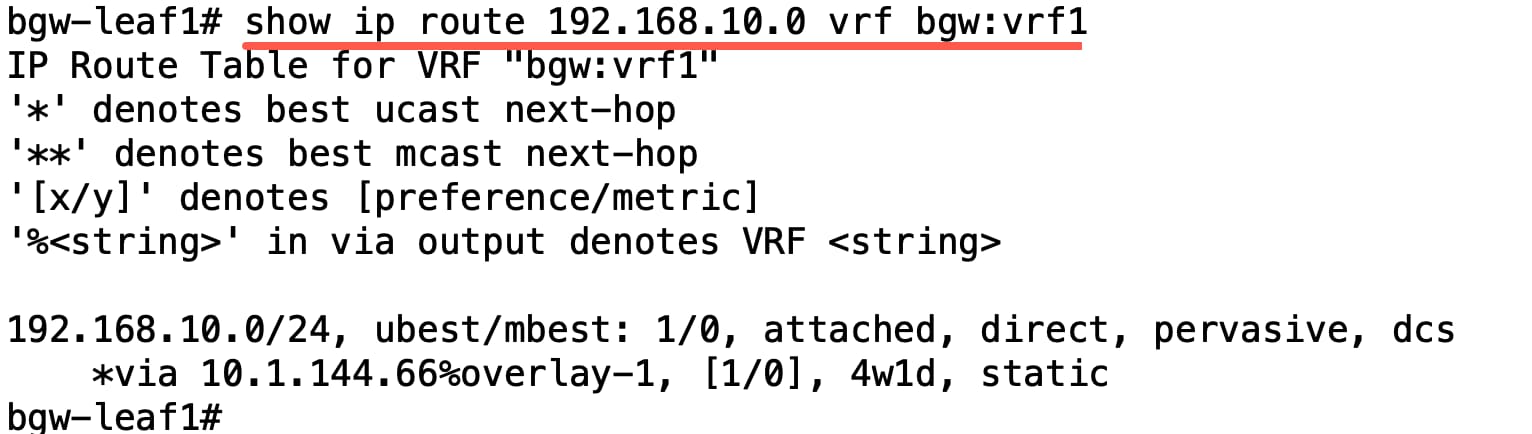
Figure 165. ACI Site 1 First Border Gateway advertises EVPN Type-5
As mentioned above, all Border Gateways in ACI Site 1 advertise the same BD subnet, for completion the EVPN output of the second Border Gateway (in ACI Site 1 Pod-1) and third Border Gateway (in ACI Site 1 Pod-2) are as follows:
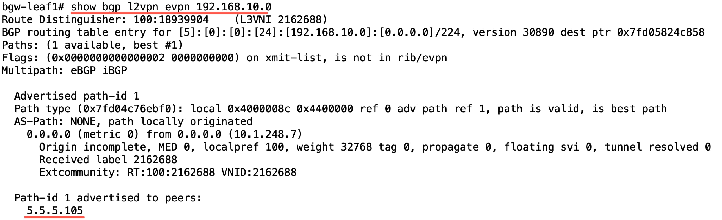
Figure 166. ACI Site 1 Second Border Gateway advertises EVPN Type-5
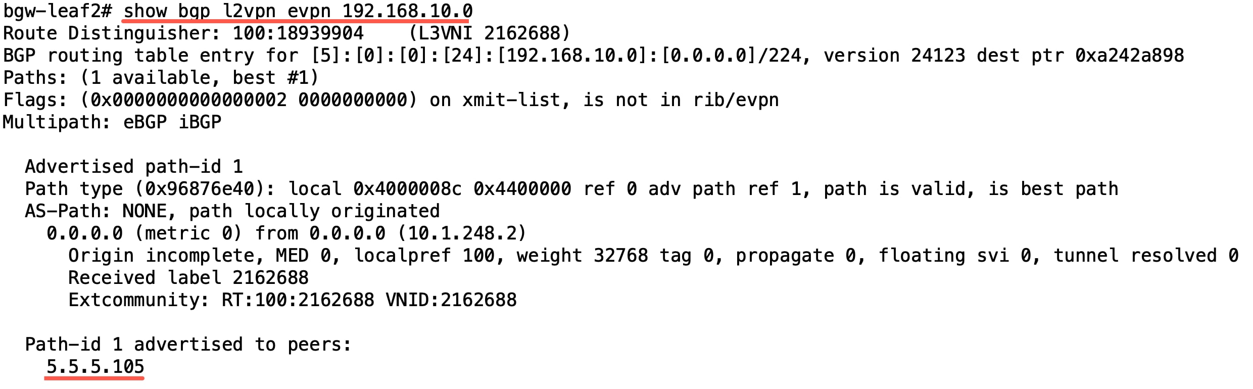
Figure 167. ACI Site 1 Third Border Gateway advertises EVPN Type-5
As a result, ACI Site 2 Border Gateways receive the route to 192.168.10.0/24 through BGP EVPN from three Border Gateways in ACI Site 1.
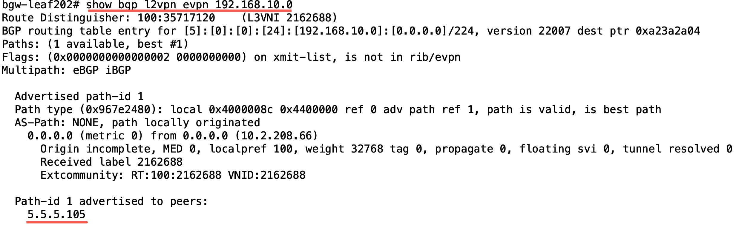
Figure 168. ACI Site 2 Border Gateway receive EVPN Type-5
● 100.100.100.102: ACI Site 1 Pod-1 Multi-Site External VIP (Anycast External VIP)
● 1.1.1.101: ACI Site 1 Pod-1 first Border Gateway TEP (EVPN loopback)
● 1.1.1.102: ACI Site 1 Pod-1 second Border Gateway TEP (EVPN loopback)
● 200.200.200.202: ACI Site 1 Pod-2 Multi-Site External VIP (Anycast External VIP)
● 2.2.2.202: ACI Site 1 Pod-2 Border Gateway TEP (EVPN loopback)
The field “Path-id 1 not advertised to any peer” means ACI Site 2 Border Gateway receives the EVPN Type-5 route, but it does not forward this route (re-advertise) through BGP EVPN. Instead, this route is then advertised to ACI Site 2 Spine through BGP VPNv4. ACI Site 2 Spine then reflects the route to ACI Site 2 compute leaf. As a result on ACI Site 2 compute leaf, the route to 192.168.10.0/24 is received in BGP VPNv4 table then is installed in the routing table.
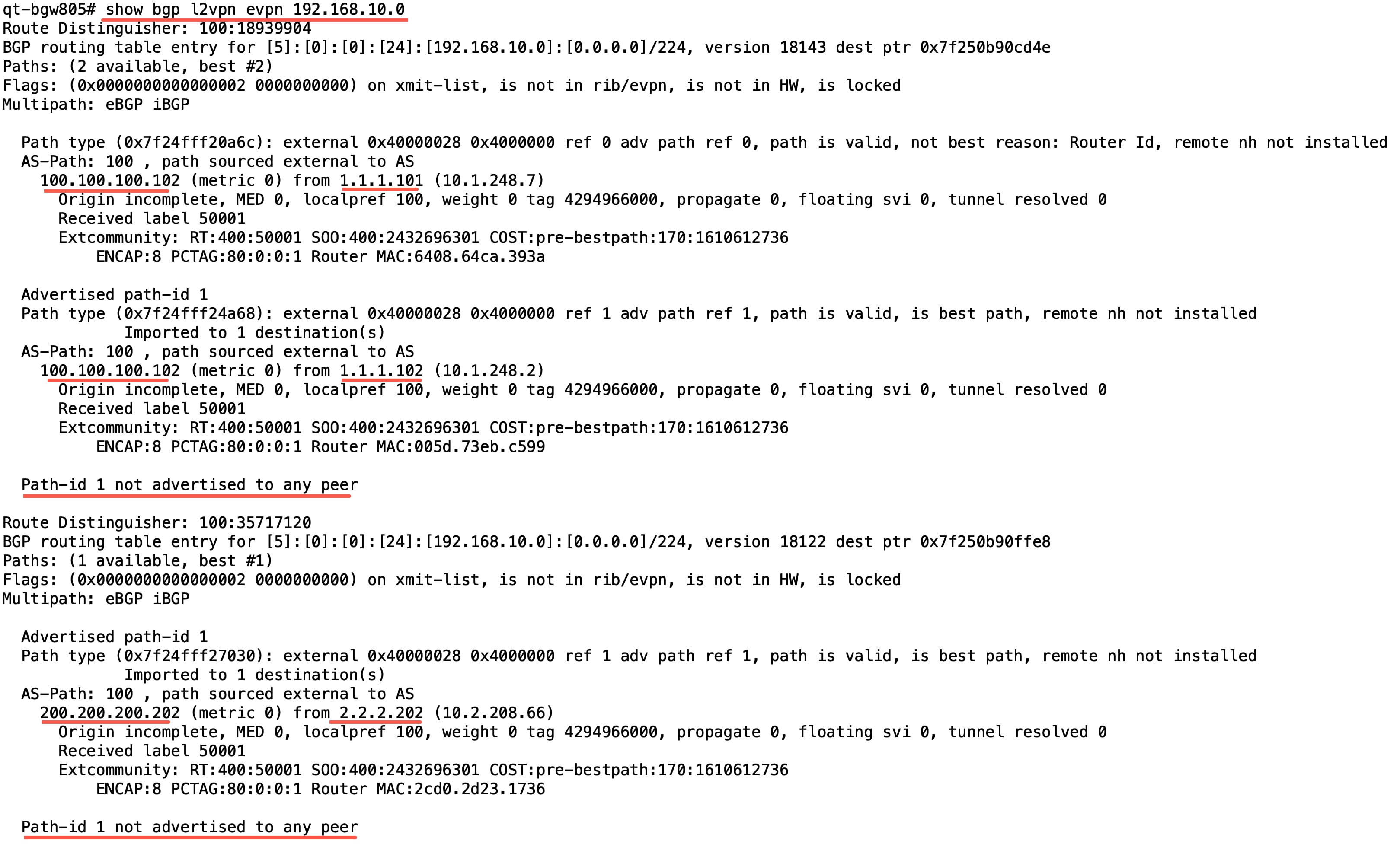
Figure 169. ACI Site 2 compute leaf BGP VPNv4
The route is installed in the compute leaf routing table with the Border Gateway PTEP as the next hop.
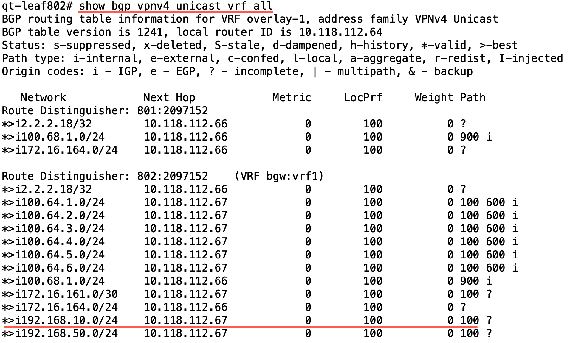
Figure 170. ACI Site 2 compute leaf routing table
Following the same procedure, IP subnet route 192.168.20.0/24 is advertised from ACI Site 2 to ACI Site 1. In this example, the ACI Site 1 Border Gateway receives the route through BGP EVPN and then advertises it to the ACI Site 1 spines through BGP VPNv4. The spines subsequently reflect the route to the compute leaf switches.
The Next-hop IP 105.105.105.105 is the Multi-Site External VIP (Anycast External IP) of ACI Site 2 Border Gateway, 5.5.5.105 is loopback0 IP address of ACI Site 2 Border Gateway.
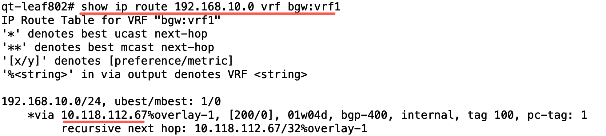
Figure 171. ACI Site 1 Border Gateway learn ACI Site 2 bd20 subnet
The IP subnet route 192.168.20.0/24 then is programmed in the routing table.
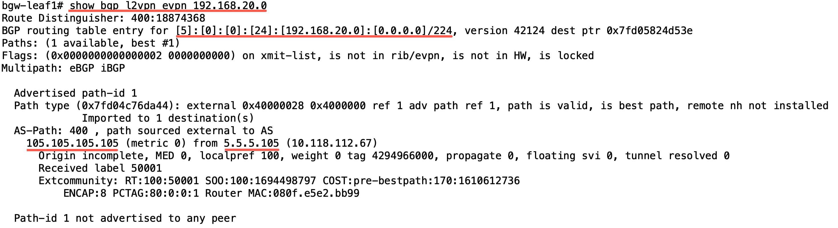
Figure 172. ACI Site 1 Border Gateway routing table
ACI Site 1 compute leaf switches have the route in its BGP VPNv4 table, then in the routing table.
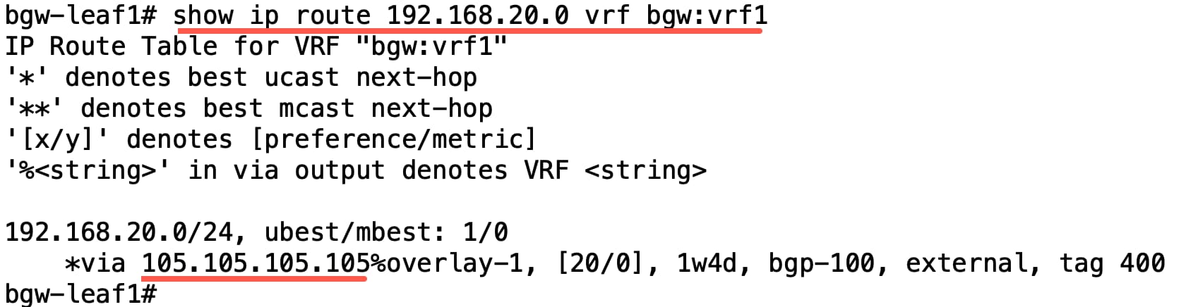
Figure 173. ACI Site 1 compute leaf BGP VPNv4 table
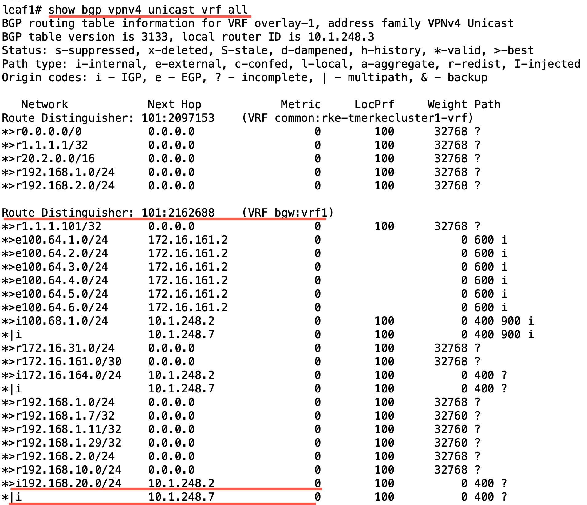
Figure 174. ACI Site 1 compute leaf routing table
Note that, in this use case, the EVPN Type-5 route does not carry pcTag information. Instead, the pcTag information is carried in the EVPN Type-2 route. This behavior is consistent with the “Inter-Subnet Communication with Stretched BDs and Multiple ESGs” use cases. ACI Site 1 Border Gateway learns EVPN Type-2 for remote endpoint 192.168.20.201 from Site 2. The figure below shows output of first Border Gateway. The pcTag 1020 is Normalized pcTag, this value later is translated to the local pcTag when the route is installed in the routing table.
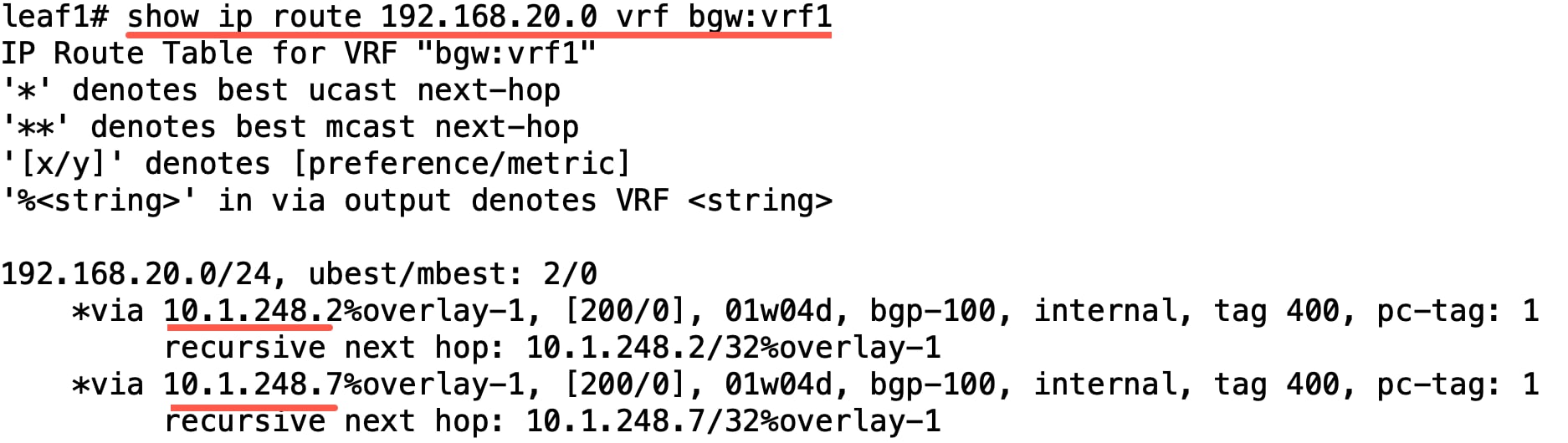
Figure 175. ACI Site 1 Border Gateway learns remote endpoint through EVPN Type-2
Note that the local pcTag is shown only when using the exec mode (default mode, non-vsh mode)
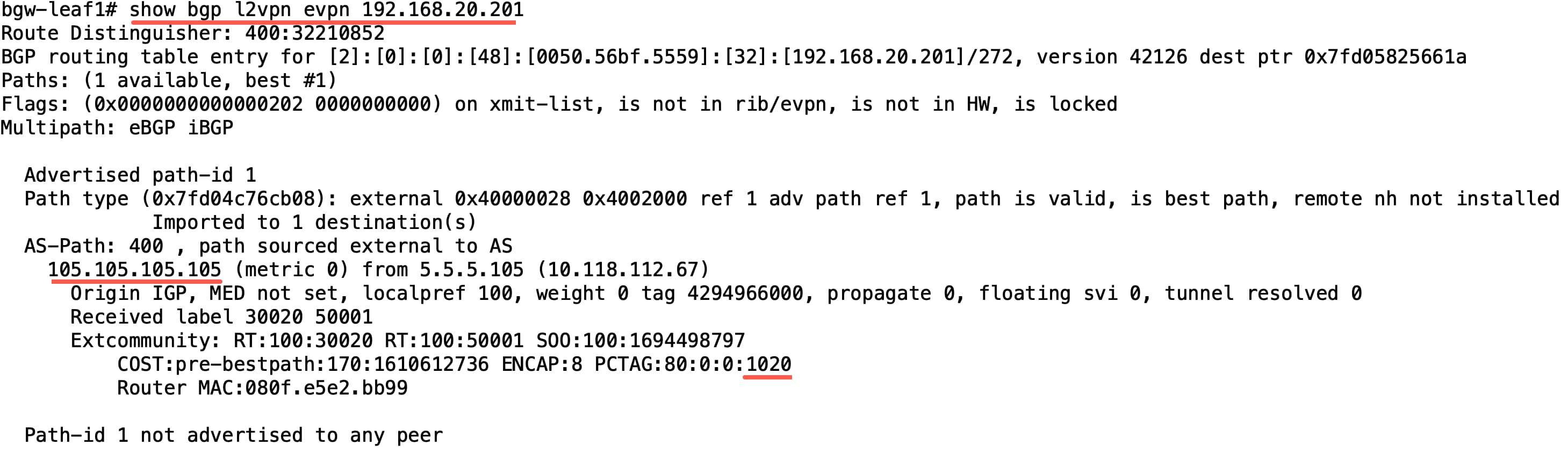
Figure 176. ACI Site 1 Border Gateway displays remote endpoint with local pcTag
Data Plane Verification
Because ESG esg1020 is deployed in both sites with the same Normalized pcTag, endpoints within this ESG can communicate each other across both ACI sites without a contract.

Figure 177. ACI Site 1 esg1020 endpoint
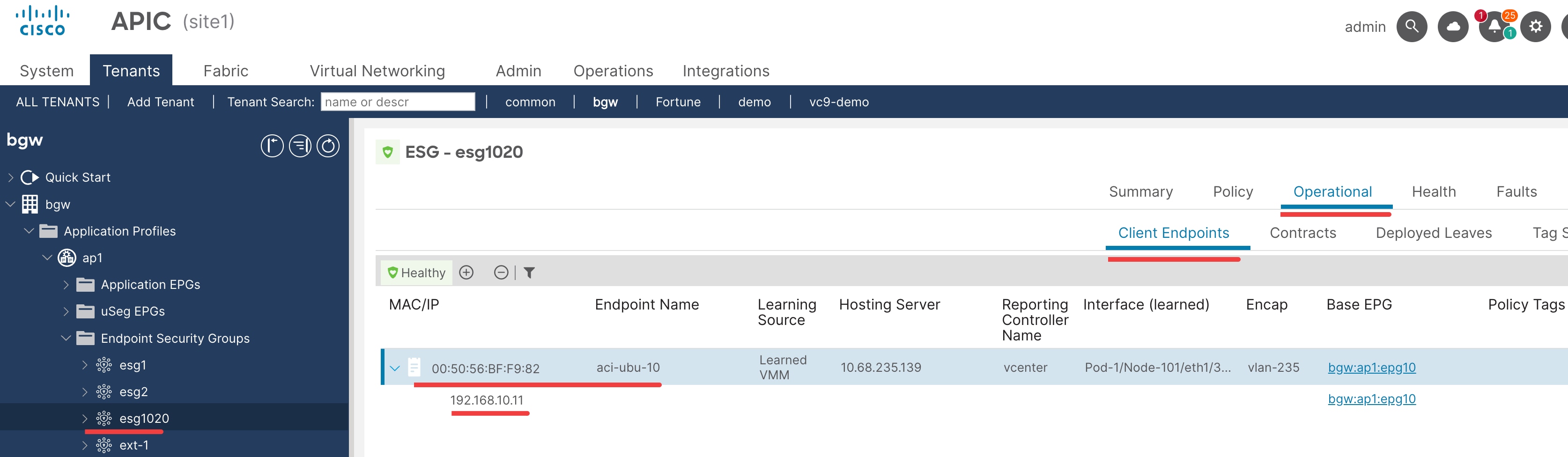
Figure 178. ACI Site 2 esg1020 endpoint
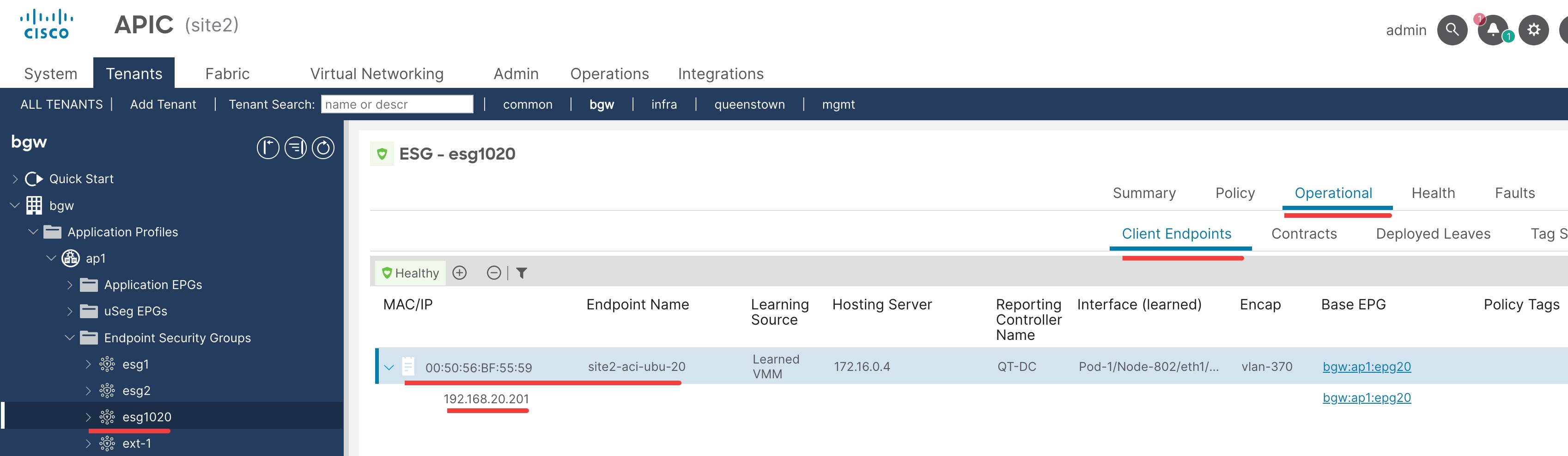
Figure 179. Data plane Inter-Subnet Communication with Non-stretched BDs and Single ESG
An endpoint in ESG esg1020 in ACI Site 1 can ping an endpoint in the same ESG in ACI Site 2. The following packet capture was obtained via ERSPAN traffic from ISN device. The packet capture of the ICMP request from EP-10 to EP-20 confirms that the Layer 3 (VRF) Normalized VNI is used in the VXLAN header for inter-site data plane forwarding.
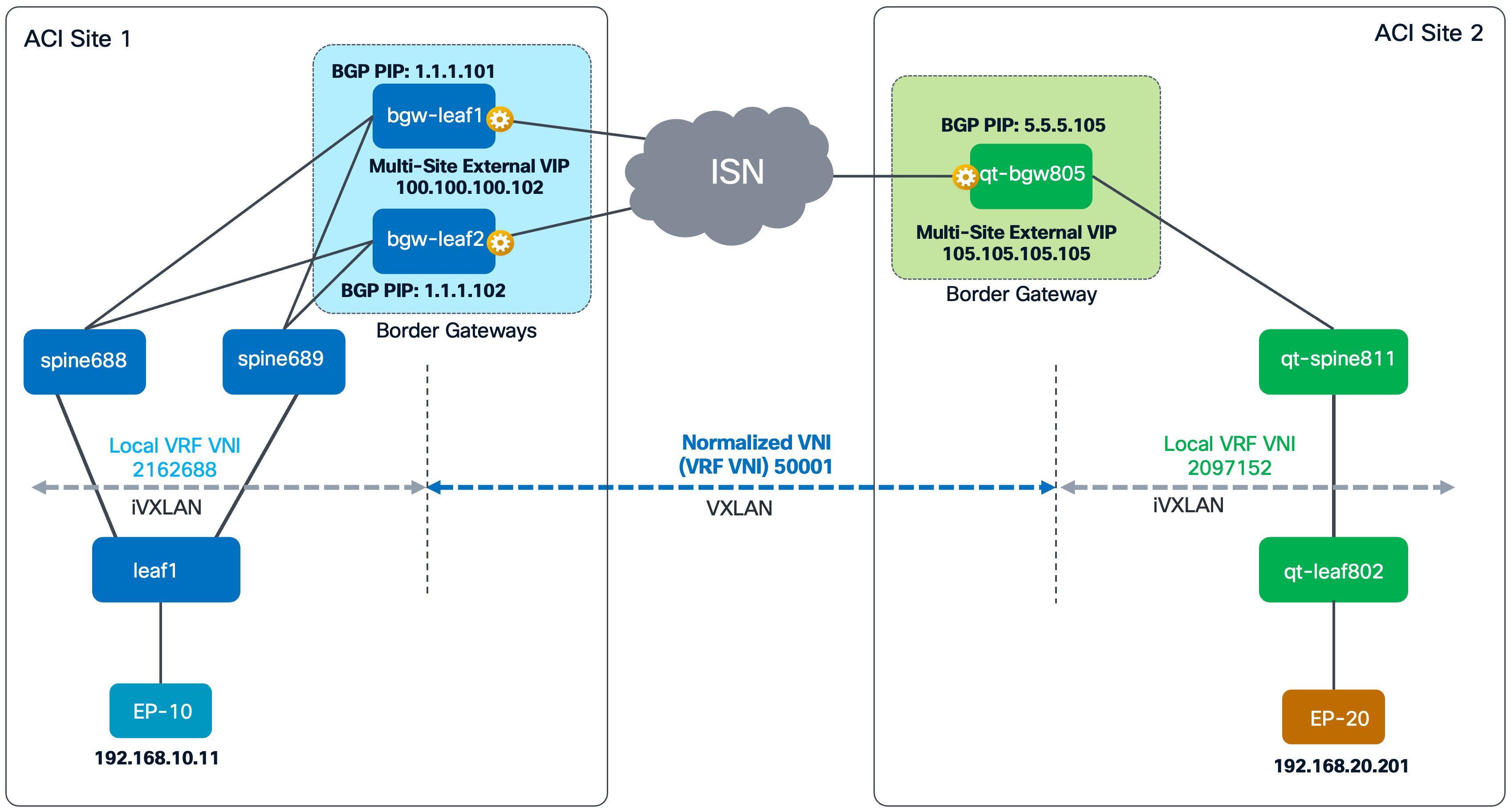
Figure 180. ICMP request from EP-10 (192.168.10.11) to EP-20 (192.168.20.201)
The packet capture of the ICMP reply from EP-20 to EP-10 confirms that the Layer 3 (VRF) Normalized VNI is used in the VXLAN header for inter-site data plane forwarding.
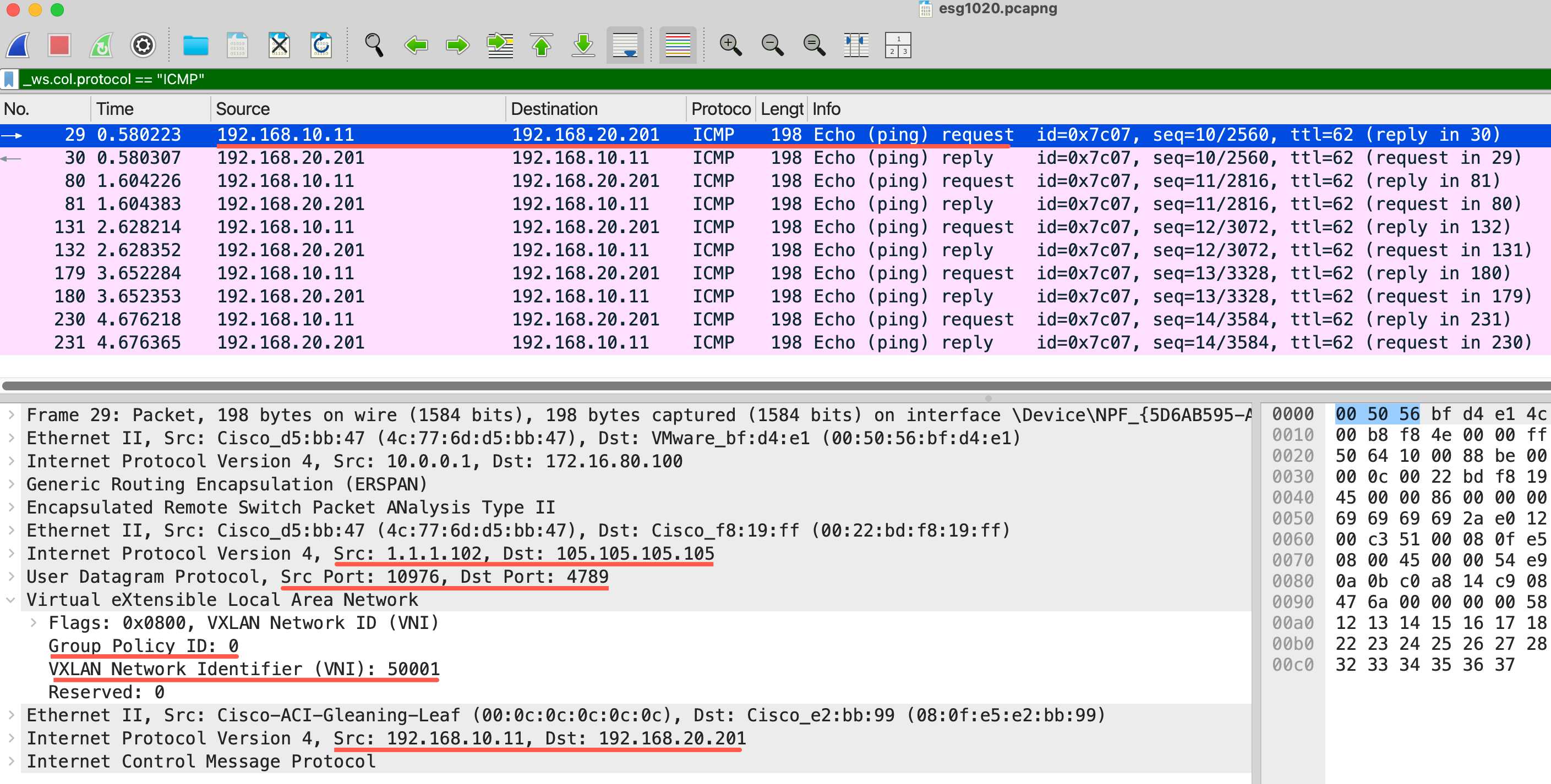
Figure 181. ICMP reply from EP-20 (192.168.20.201) to EP-10 (192.168.10.201)
From a policy enforcement location perspective, this use case is identical to the previous use case, “Inter-Subnet Communication with Stretched BDs and Multiple ESGs” between ESGs. Although endpoints 192.168.10.11 (Site 1) and 192.168.20.201 (Site 2) are members of the same ESG (esg1020), their communication is inter-subnet (routed), which is same as the previous use case. The topology below illustrates the policy enforcement points for traffic originating in Site 1 and destined for Site 2. The same logic applies to the return path from Site 2 to Site 1; the egress switch enforces the policy in each site.
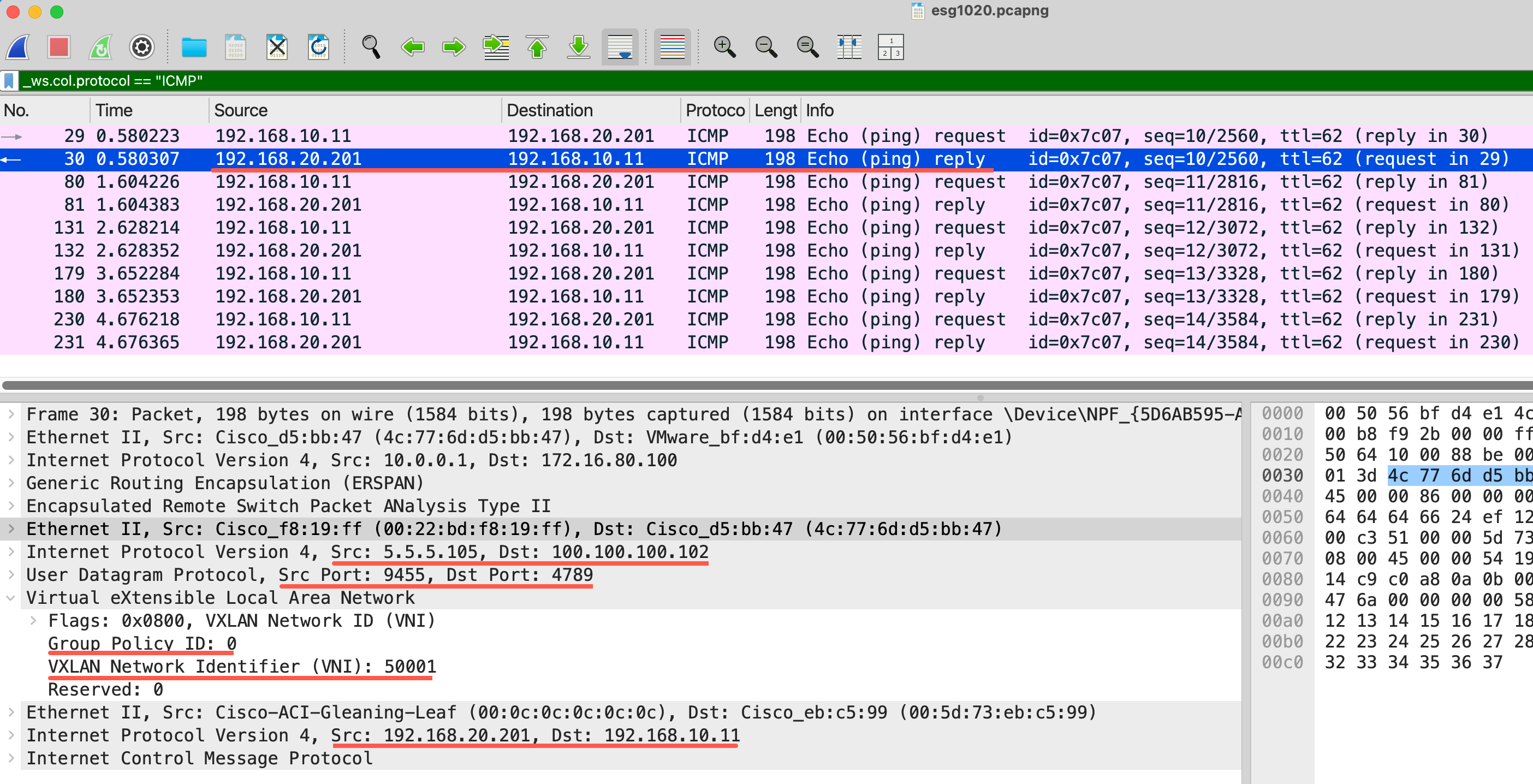
Figure 182. Intra-ESG Inter-Subnet communication policy enforcement
In ACI Site 2, although Border Gateway has endpoint information advertised by local spine, it ignores the IP part to save hardware resource, the Border Gateway does not enforce policy, instead the compute leaf attached to the destination endpoint enforces policy based on the locally learned endpoint information.
Use Case 4: Inter-Subnet Communication with Non-stretched BDs and Multiple ESGs
This use case describes communication between endpoints residing in different subnets. It is similar to Use Case 3: Inter-Subnet Communication Non-stretched BDs and Single ESG; however, the main difference lies in the security segmentation model based on ESGs. In this use case, each site contains two ESGs: one ESG is used for local endpoint classification, with an ESG selector for actual endpoints assigned to it, and the other ESG is used for remote endpoint classification, this ESG does not need any local ESG selectors.
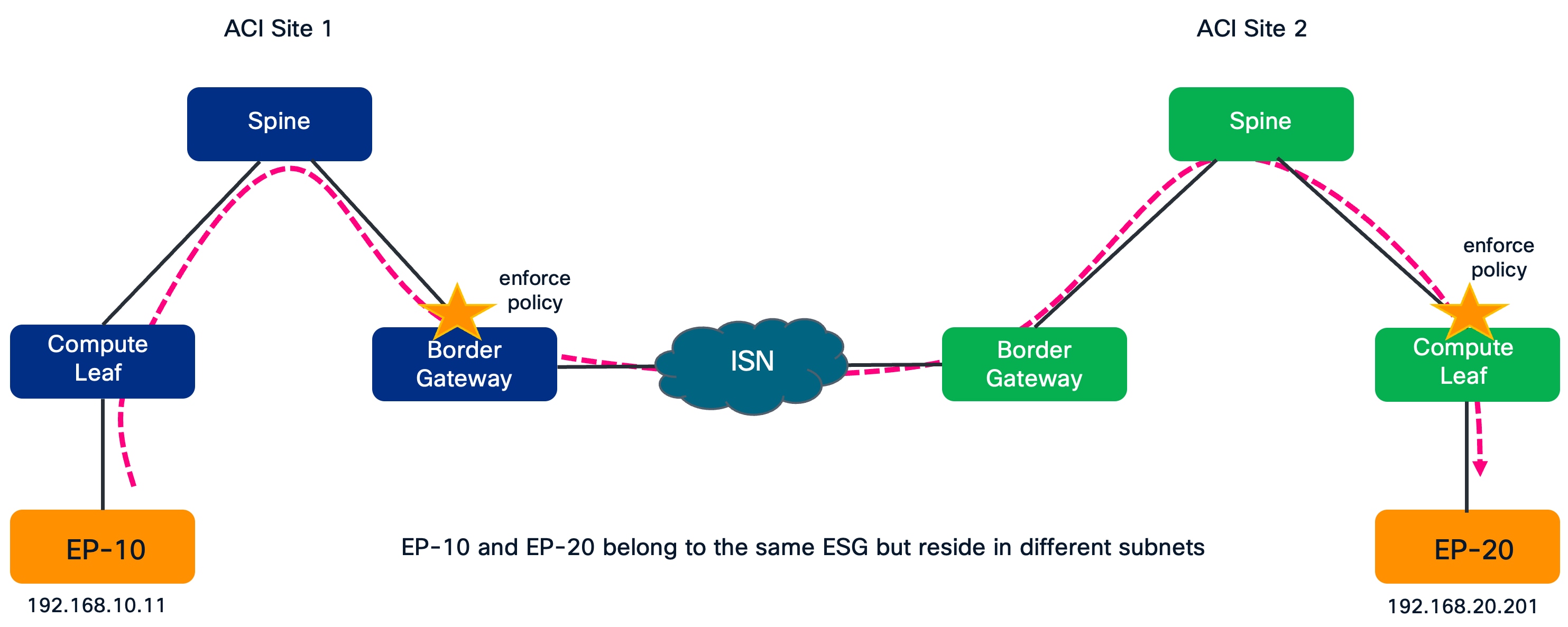
Figure 183. Inter-Subnet Communication Non-stretched BD Multiple ESGs
As shown in the above diagram, all the objects including ESGs and BDs are locally defined. At a high level, the following are the main configuration steps, assuming that VRF vrf1 has already been deployed and stretched across the sites.
Create non-stretched local Bridge Domain, ESGs, Contract
On ACI Site 1 create Bridge Domain bd50:
● L2 Unknown Unicast: Flood
● L3 Configurations: Unicast Routing (checked)
◦ Subnet 192.168.50.254/24 has scope Advertised Externally
The “Advertised Externally” scope must be enabled to allow subnet advertisement to the remote ACI site.
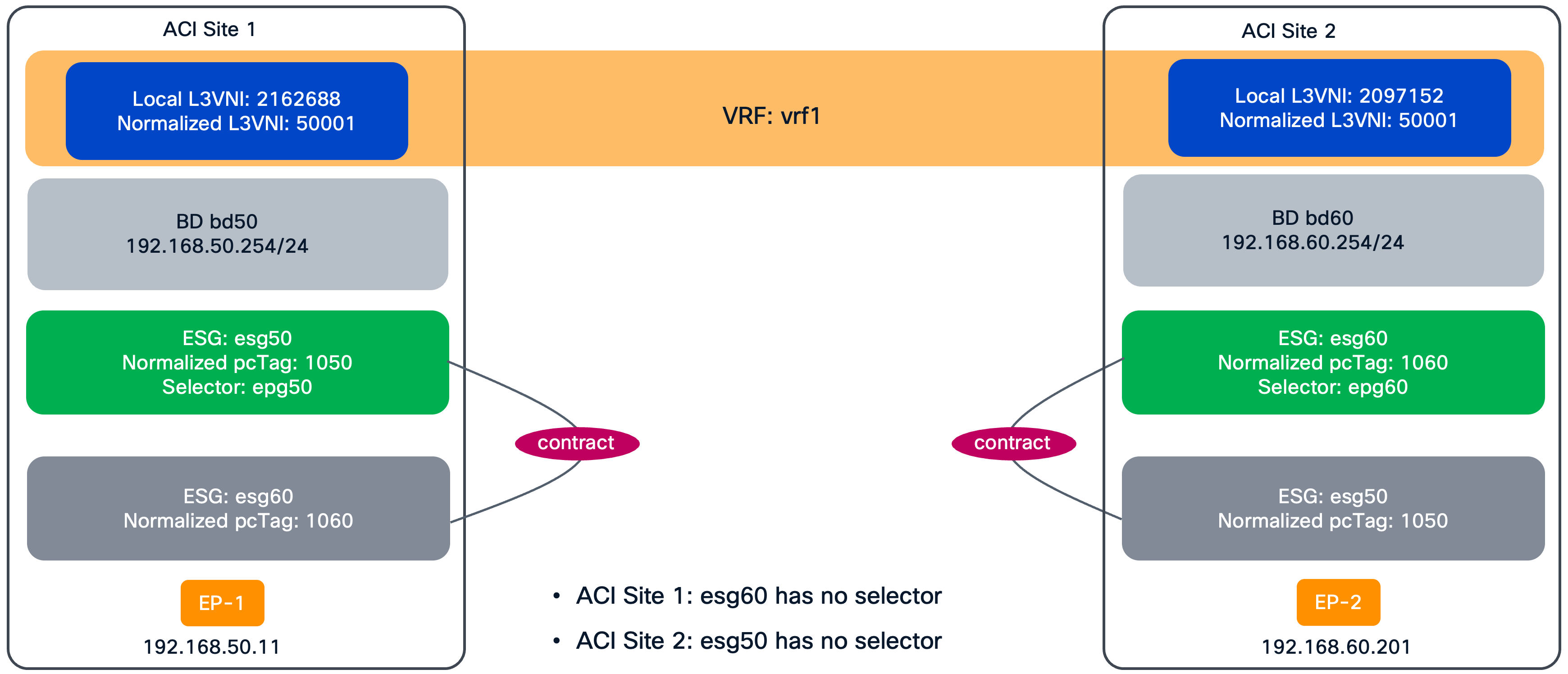
Figure 184. ACI Site 1 bd50 L2 Unknown Unicast Flood
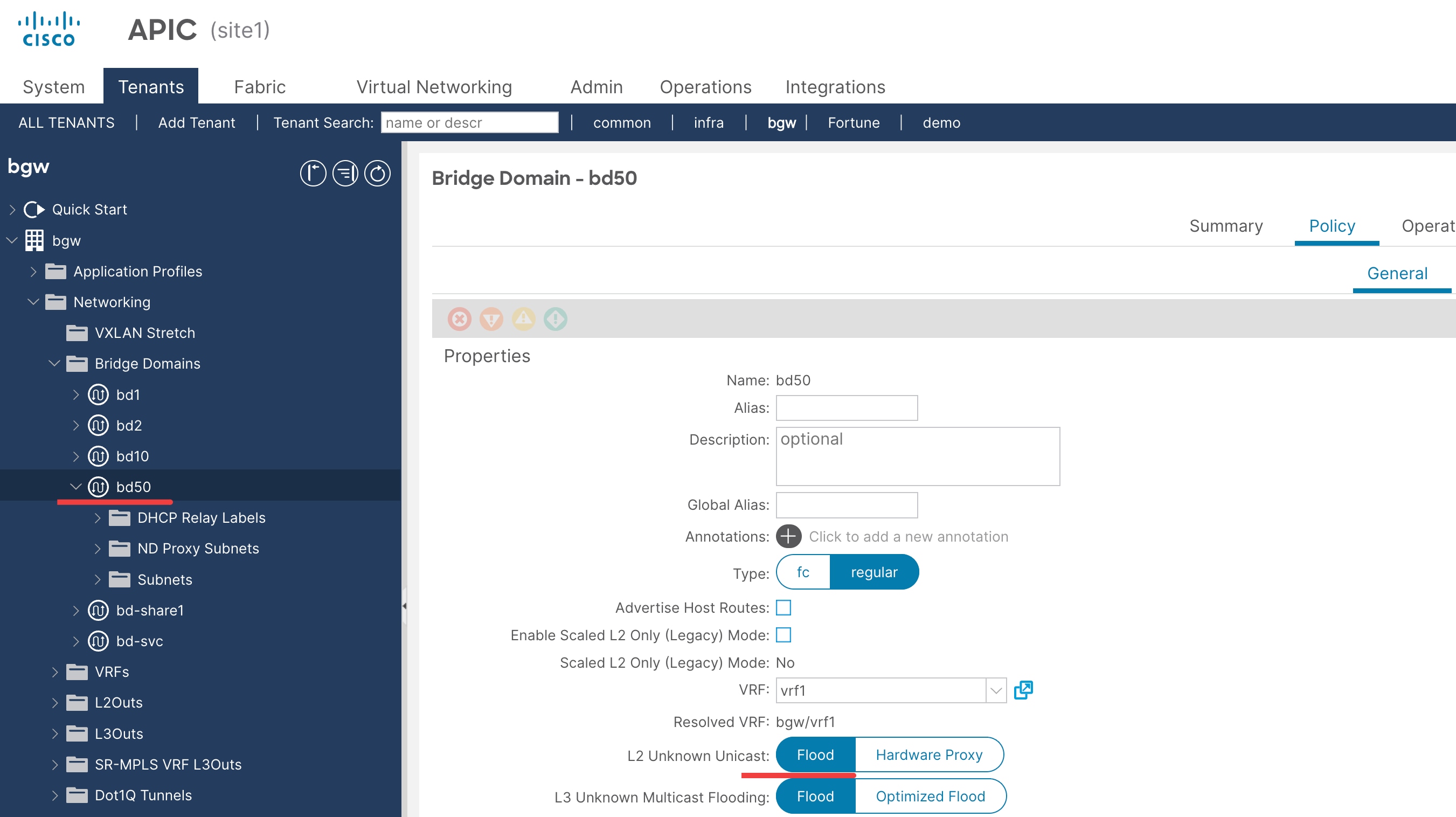
Figure 185. ACI Site 1 bd50 L3 Configurations
Deploy BD bd50 by associating it with the Border Gateway. A Bridge Domain is considered local to a site when its Normalized VNI is unique across multiple ACI sites. In this example, Normalized VNI 30050 is assigned to bd50. Conversely, in ACI Site 2, Normalized VNI 30060 is assigned to bd60.
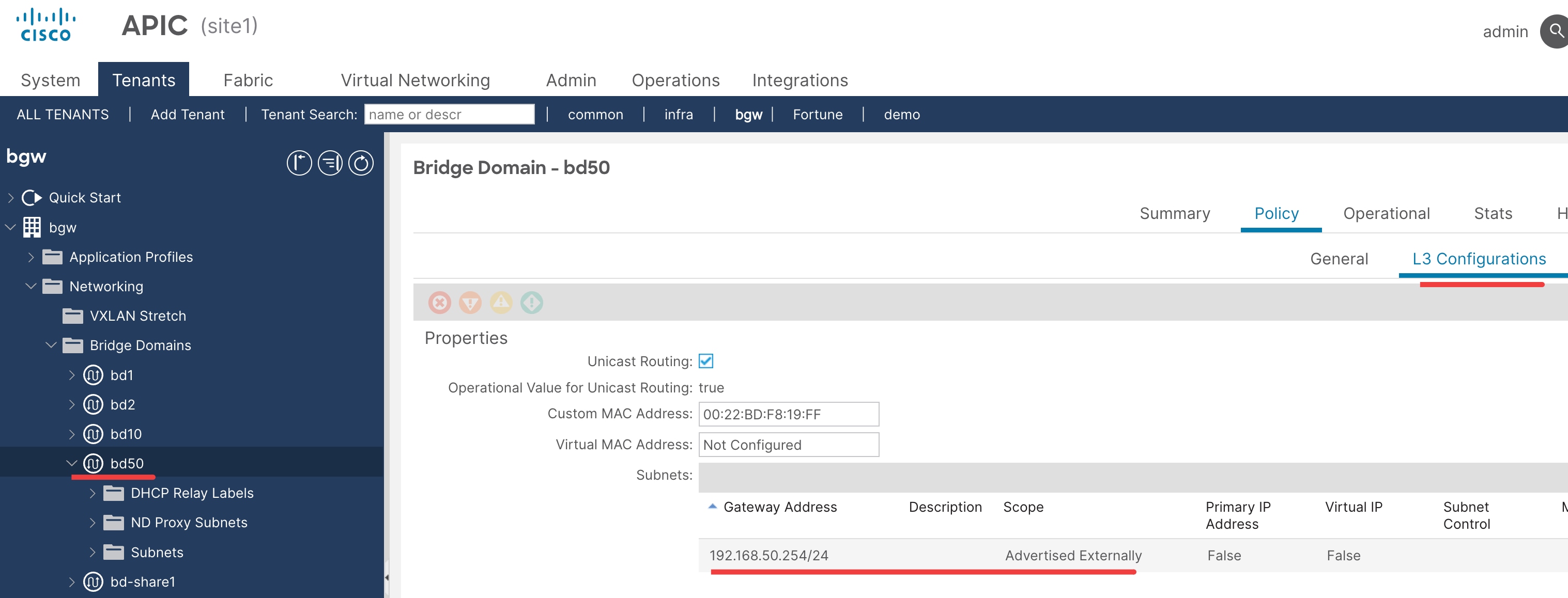
Figure 186. ACI Site 1 deploy bd50 on border gateway
Create epg50 and associate it to bd50, then create esg50 using epg50 as EPG Selector.
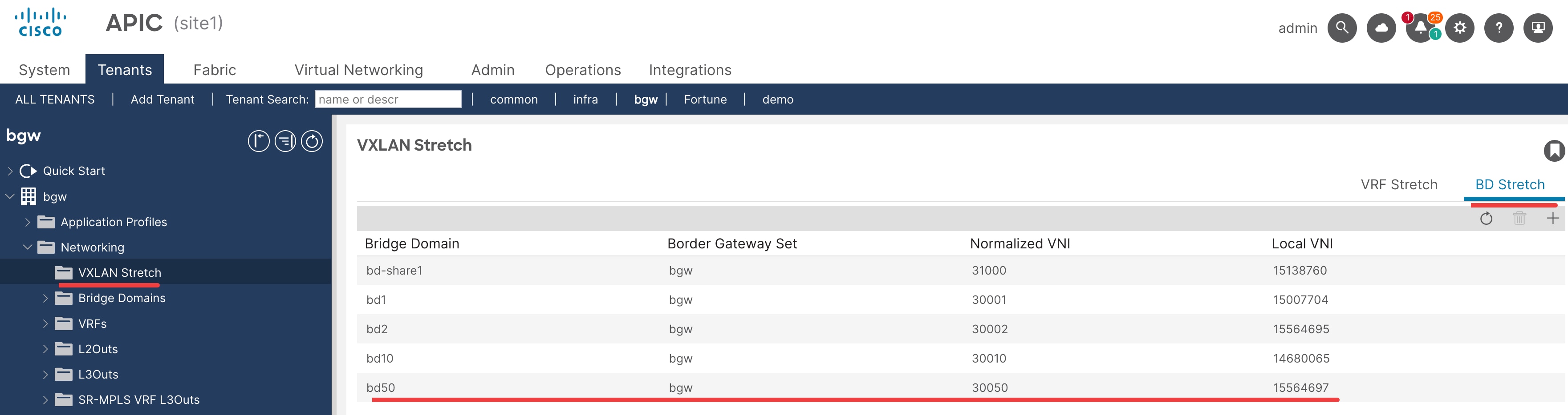
Figure 187. ACI Site 1 epg50
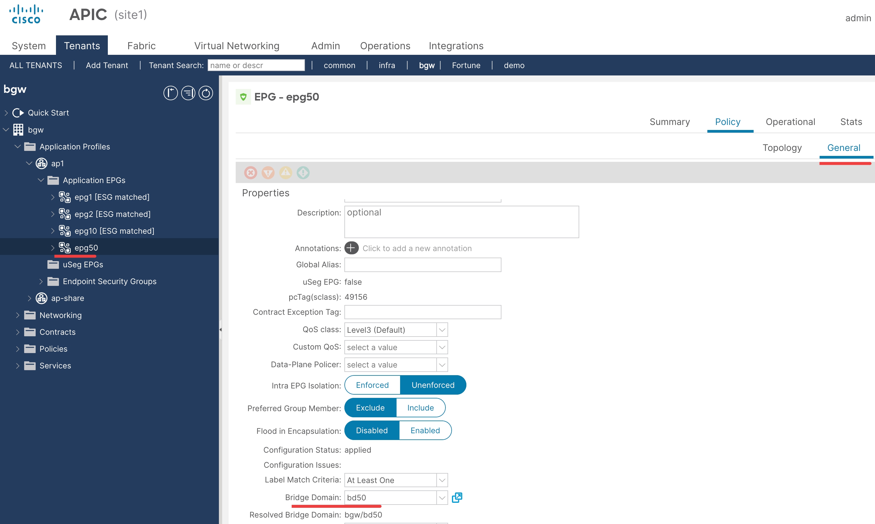
Figure 188. ACI Site 1 esg50 EPG Selector
Set the Normalized pcTag to 1050 for ESG esg50.
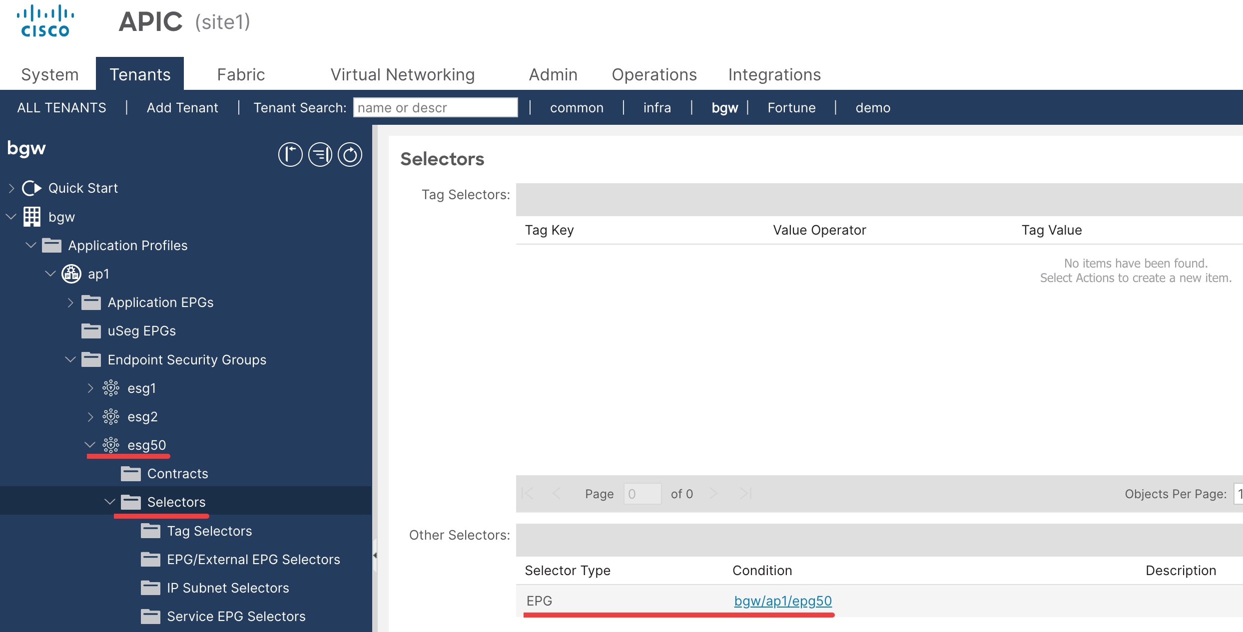
Figure 189. ACI Site 1 esg50 Normalized pcTag
Create ESG esg60 without EPG selectors and assign a normalized pcTag of 1060. Subsequently, create and apply a contract between esg50 and esg60 to permit traffic from esg60 endpoints in ACI Site 2 to esg50 endpoints in ACI Site 1.
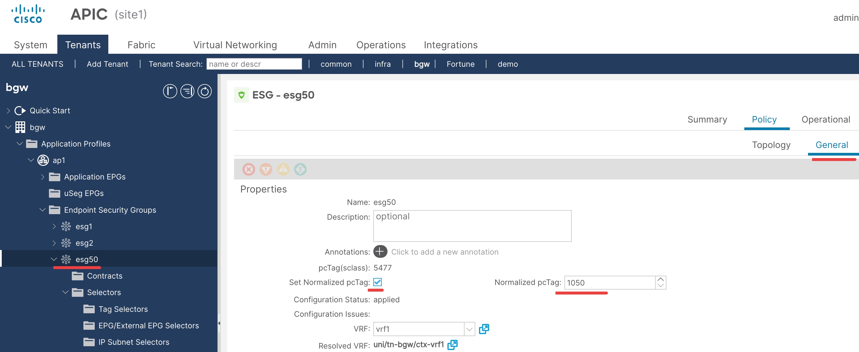
Figure 190. ACI Site 1 esg60 without selector
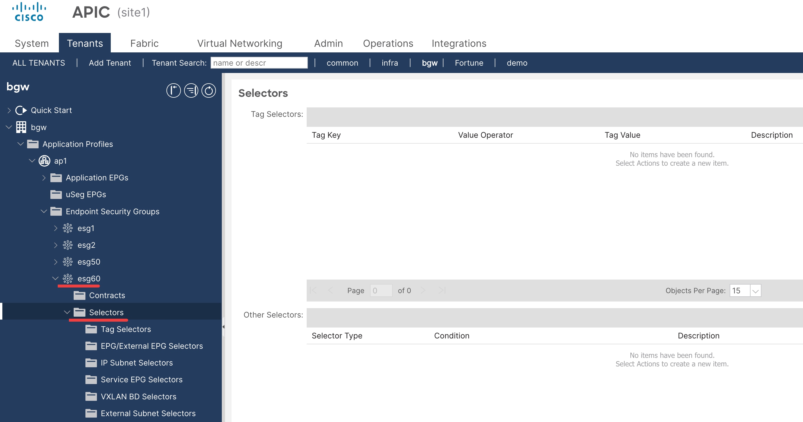
Figure 191. ACI Site 1 esg60 normalized pcTag
Create contract esg50-esg60 with permit IP filter. Since the ESGs are in the same VRF, the scope is set to VRF.
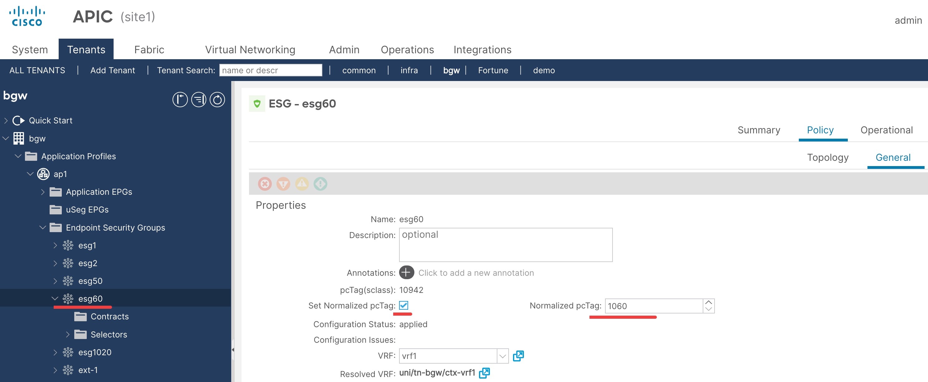
Figure 192. ACI Site 2 esg50 Normalized pcTag
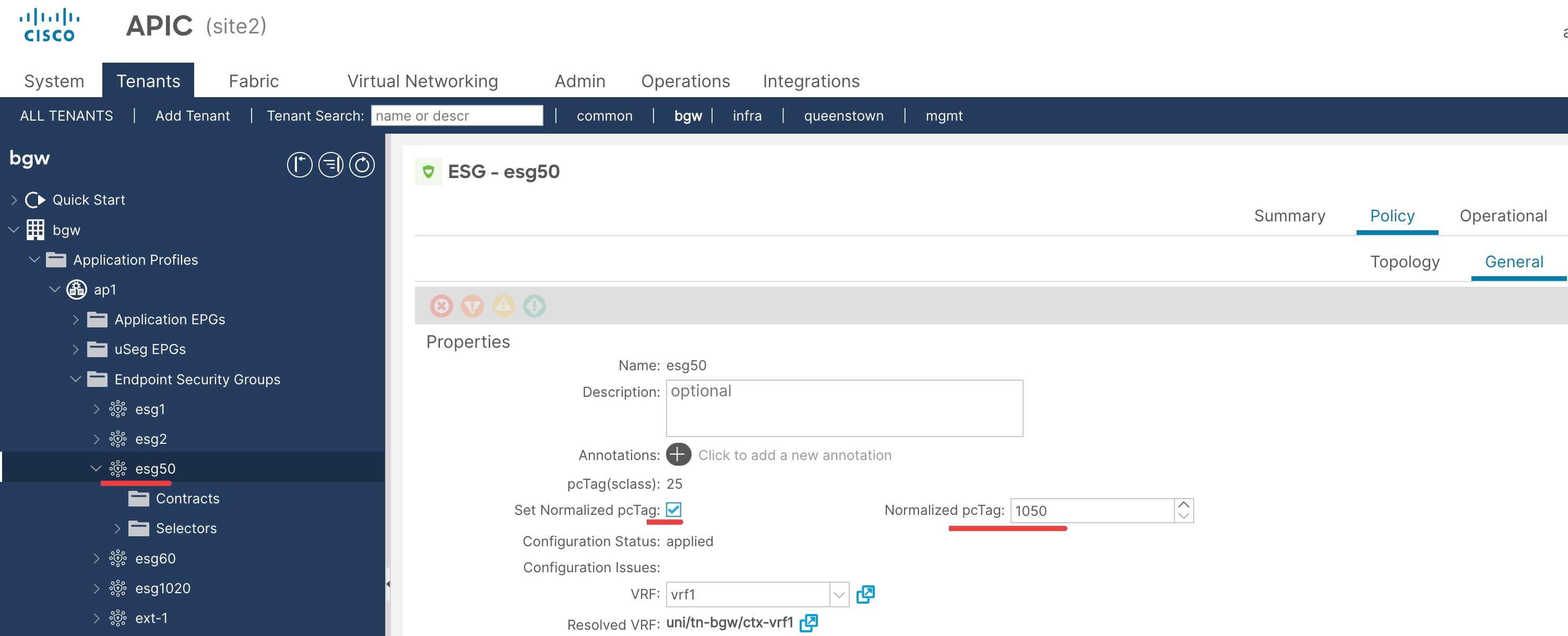
Figure 193. ACI Site 1 esg50-esg60 contract
Apply contract esg50-esg60 between ESG esg50 and esg60. The ESG esg50 is the consumer, esg60 is the provider.
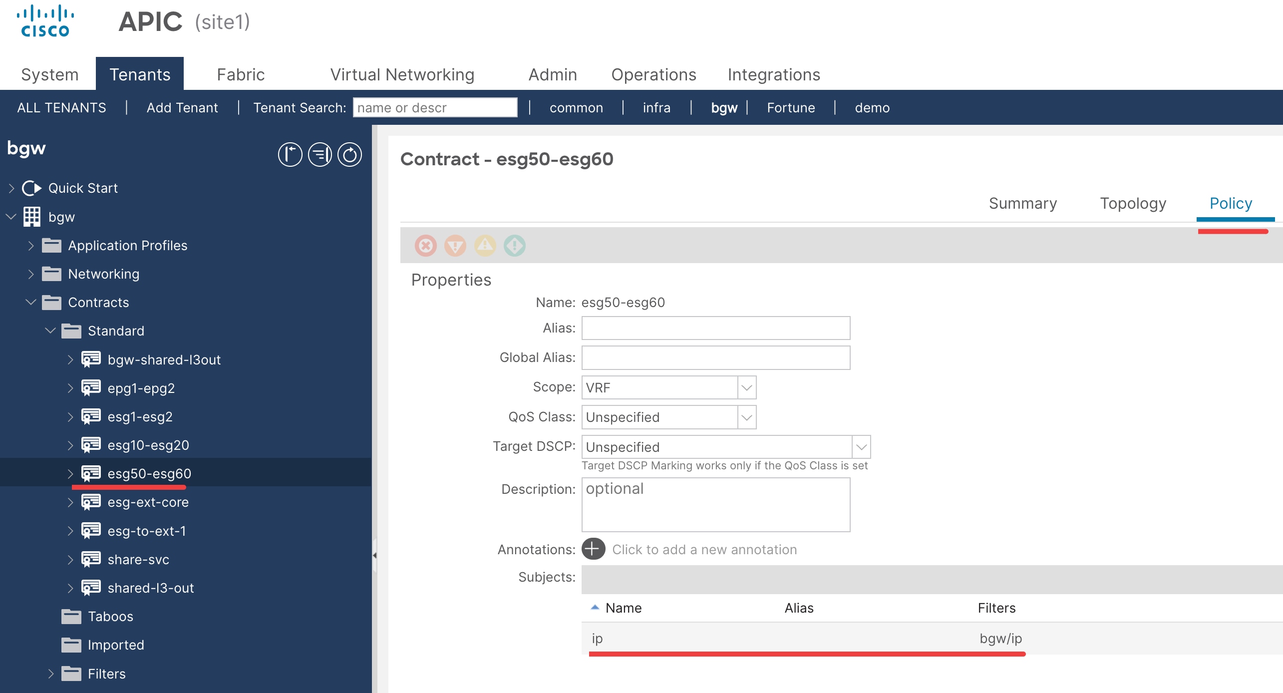
Figure 194. ACI Site 1 esg50 contract consumer
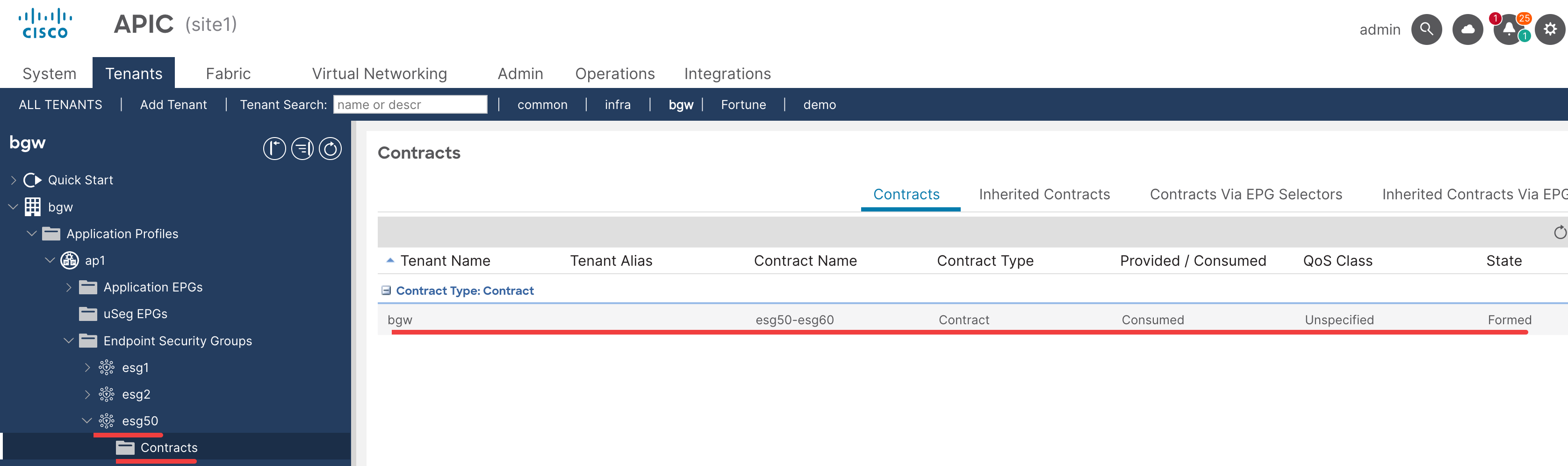
Figure 195. ACI Site 1 esg60 contract provider
On ACI Site 2 create Bridge Domain bd60:
● L2 Unknown Unicast: Flood
● L3 Configurations: Unicast Routing (checked)
◦ Subnet 192.168.60.254/24 has scope Advertised Externally
The “Advertised Externally” scope must be enabled to allow subnet advertisements to the remote ACI site.
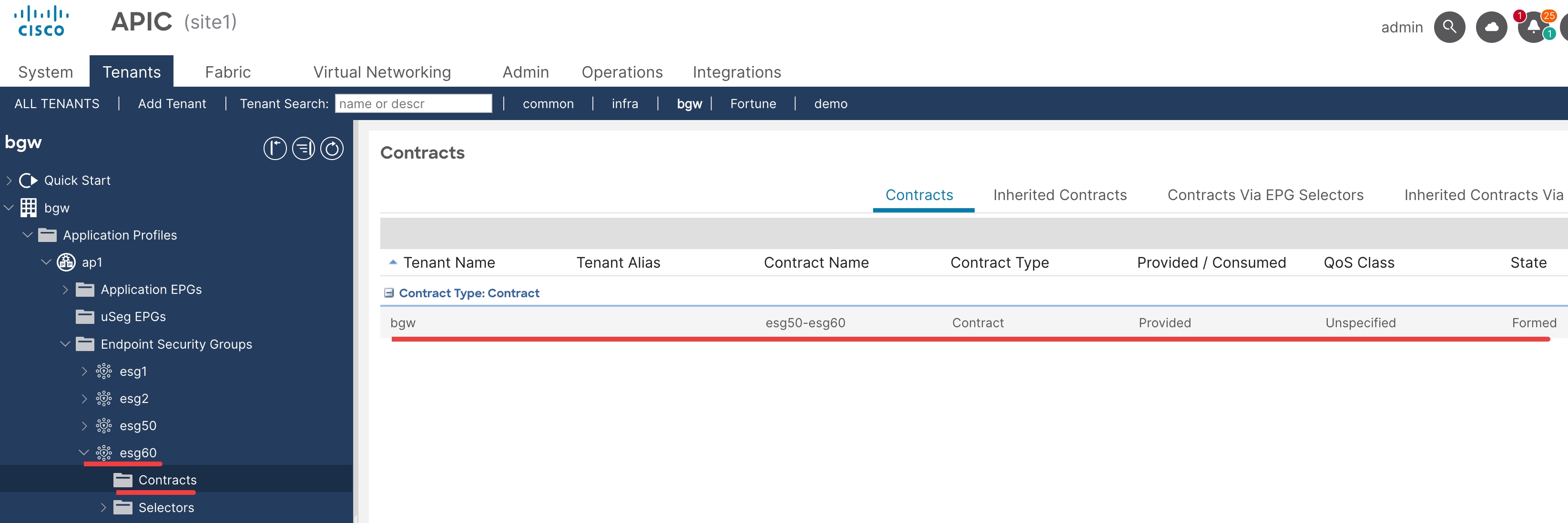
Figure 196. ACI Site 2 bd60 L2 Unknown Unicast Flood
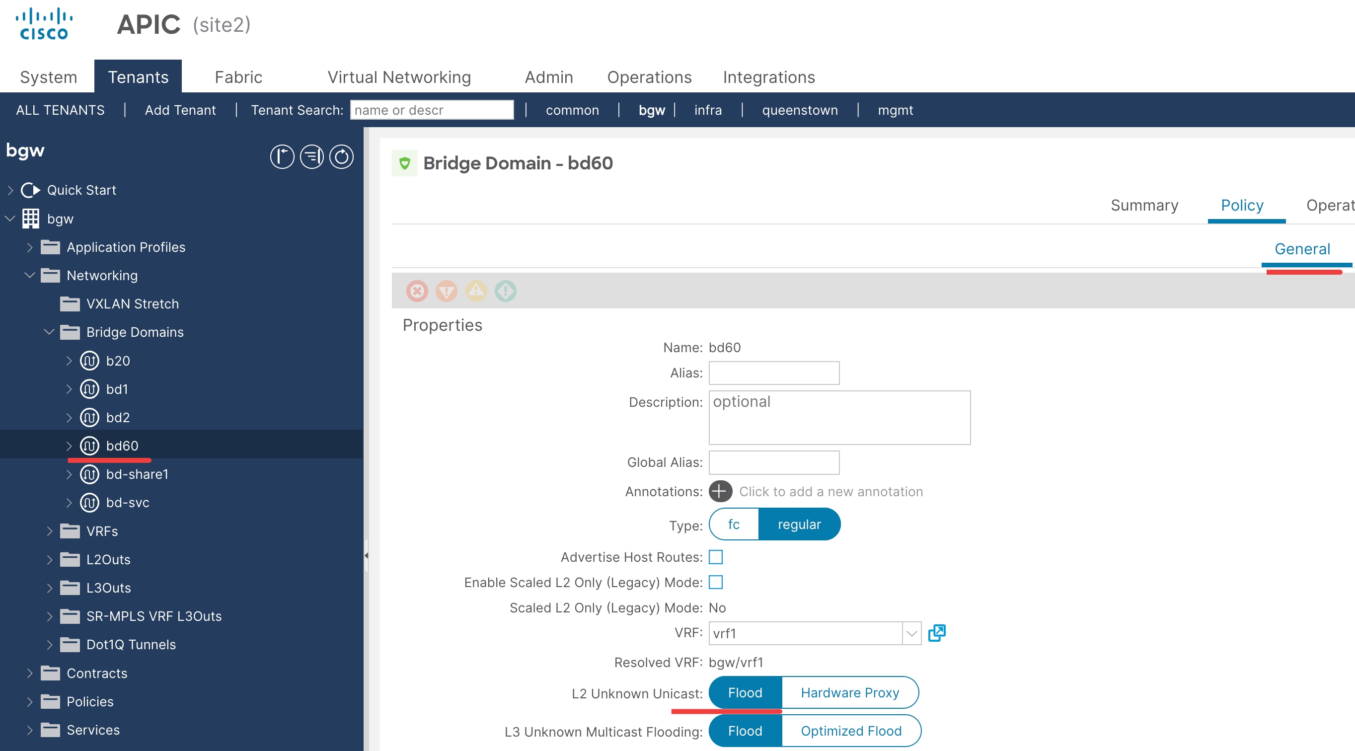
Figure 197. ACI Site 2 bd60 L3 Configurations
Deploy BD bd60 by associating it with the Border Gateway. In this example, the Normalized VNI 30060 is distinct from the VNI 30050 assigned to bd50 on ACI Site 1. This distinction indicates that bd50 on ACI Site 1 and bd60 on ACI Site 2 are independent, non-stretched entities and deployed locally on its respective site Border Gateway.
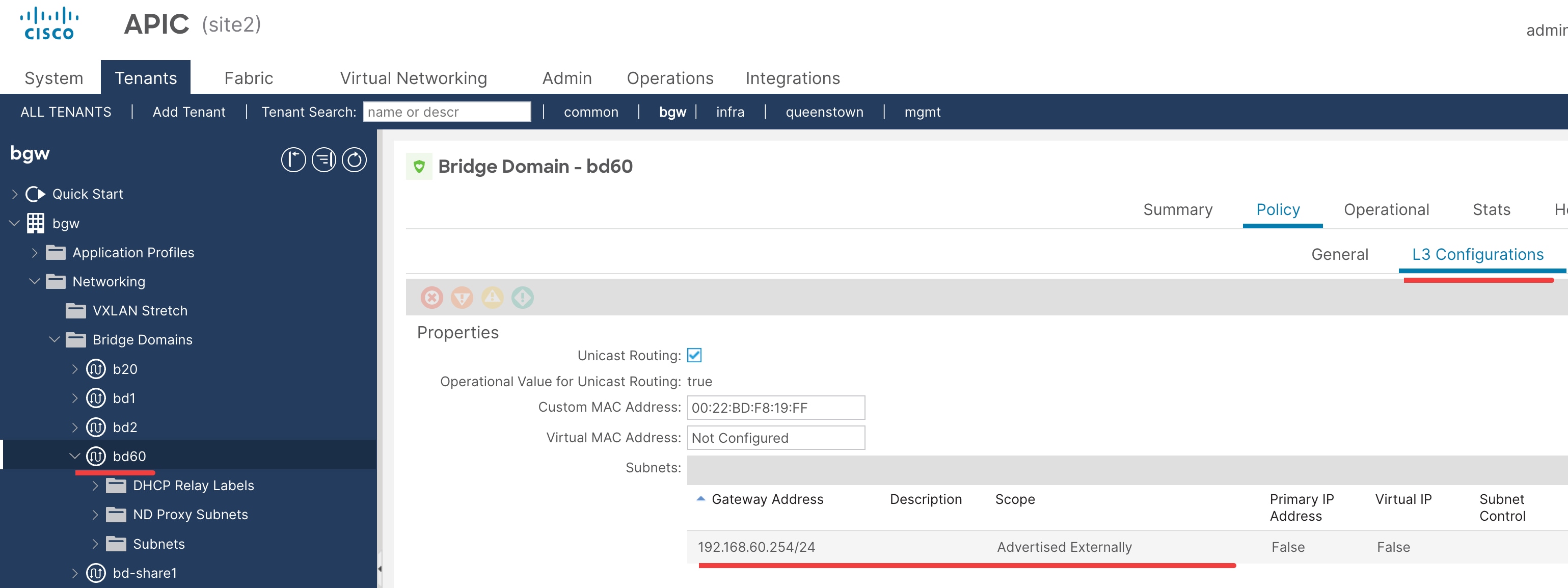
Figure 198. ACI Site 2 deploy bd60 on border gateway
Create epg60 and associate it to bd60, then create esg60 using epg60 as EPG Selector.
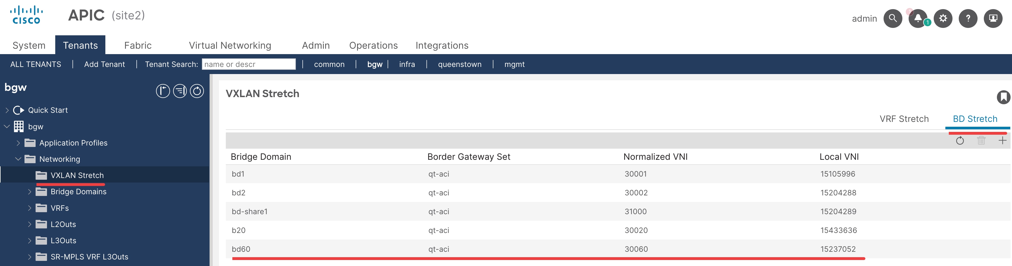
Figure 199. ACI Site 2 epg60
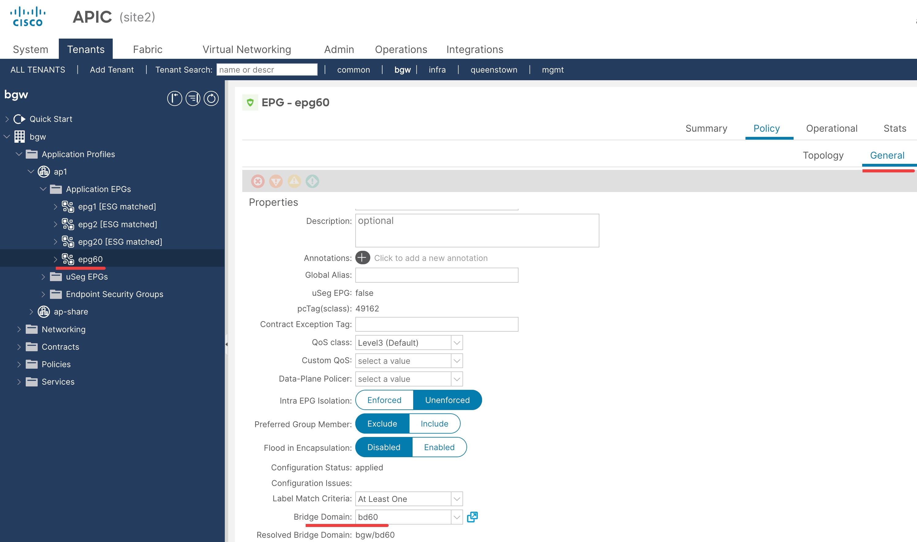
Figure 200. ACI Site 2 esg60 EPG Selector
Create ESG esg50 without EPG selectors and assign a normalized pcTag of 1050. Subsequently, create and apply a contract between esg50 and esg60 to permit traffic from esg50 endpoints in ACI Site 1 to esg60 endpoints in ACI Site 2.
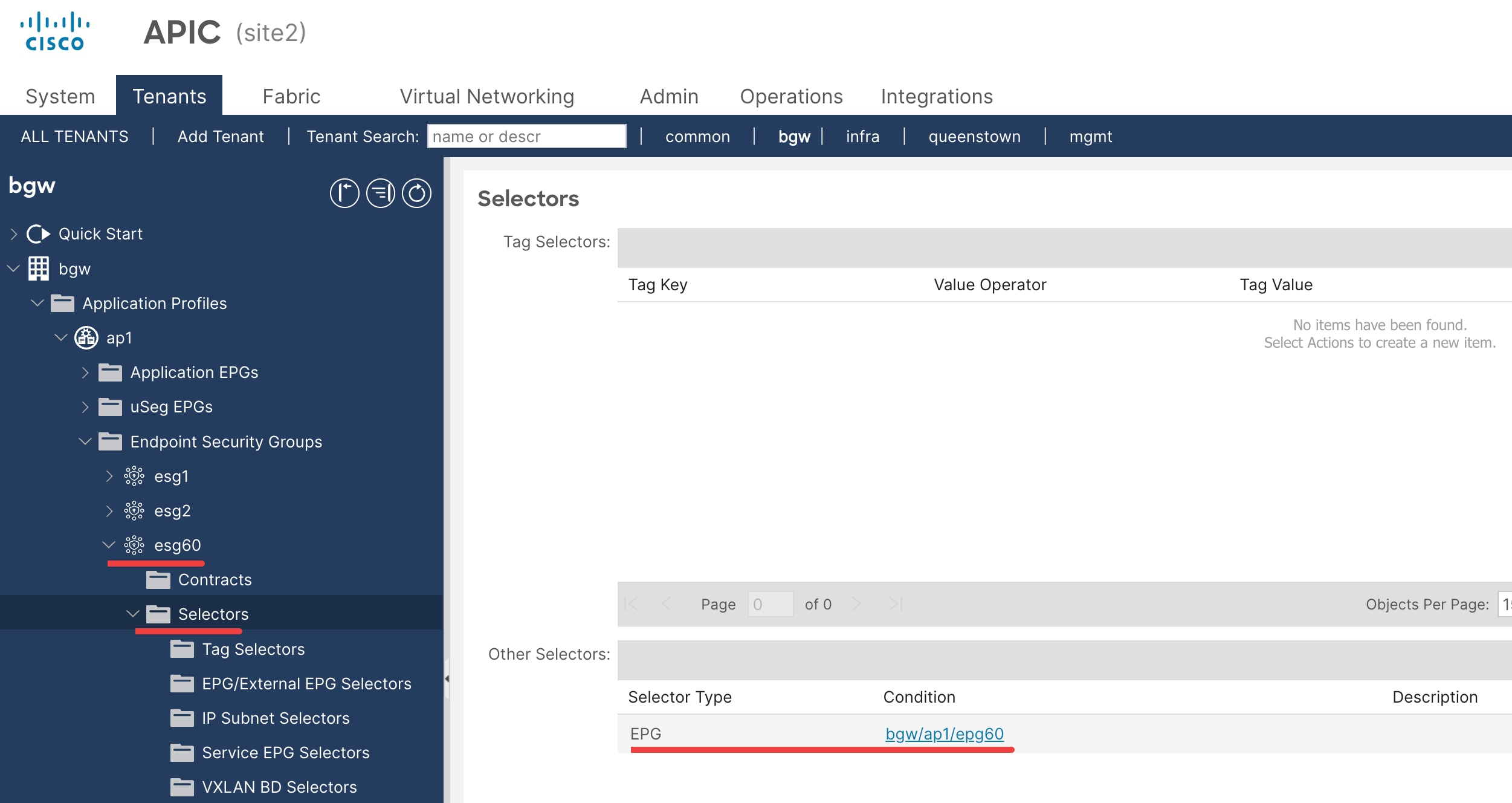
Figure 201. ACI Site 2 esg50 without selector
Create contract esg50-esg60 with permit IP filter. Since the ESGs are in the same VRF, the scope is set to VRF.
Figure 202. ACI Site 2 esg50-esg60 contract
Apply contract esg50-esg60 to ESG esg50 and esg60. The ESG esg50 is consumer, esg60 is provider.
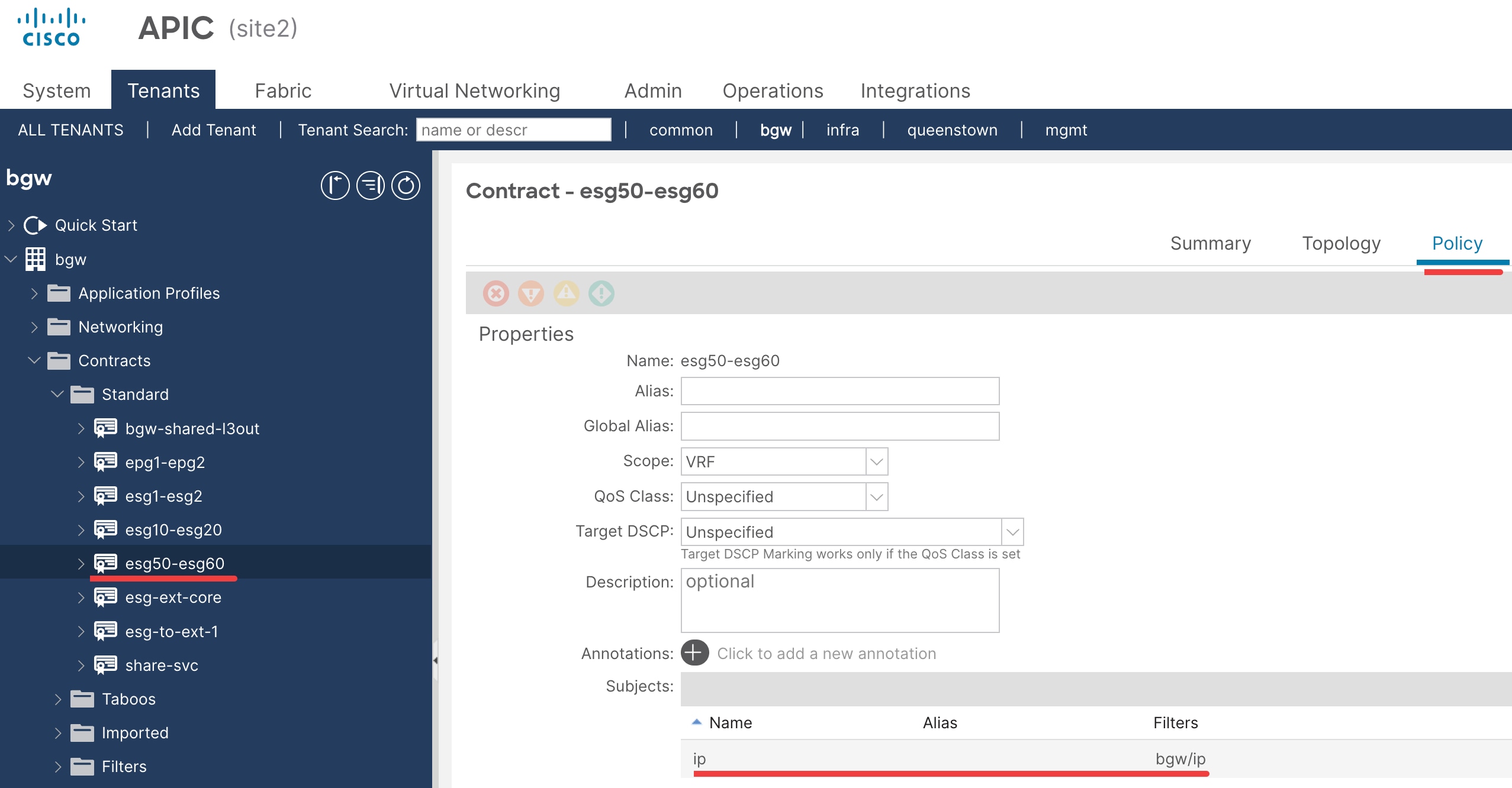
Figure 203. ACI Site 2 esg50 contract consumer
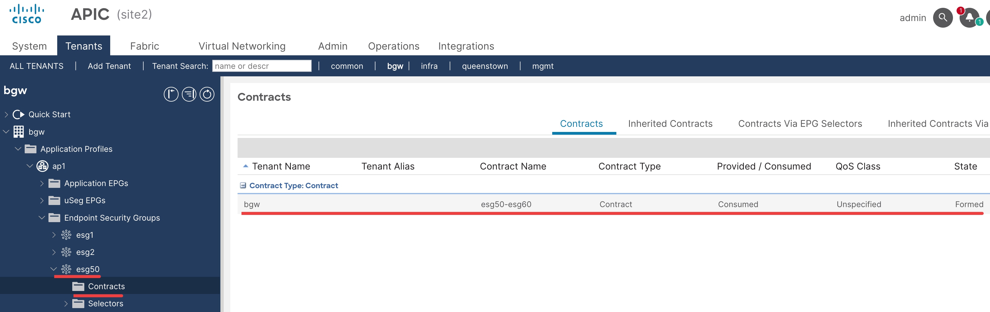
Figure 204. ACI Site 2 esg60 contract provider
Control Plane Verification
The verification steps for this use case are similar to those of the previous Use Case 3: Inter-Subnet Communication Non-Stretched BDs Single ESG. The primary difference is that this scenario includes multiple ESGs, specifically esg50 and esg60. As a result, the control-plane verification process remains largely the same.
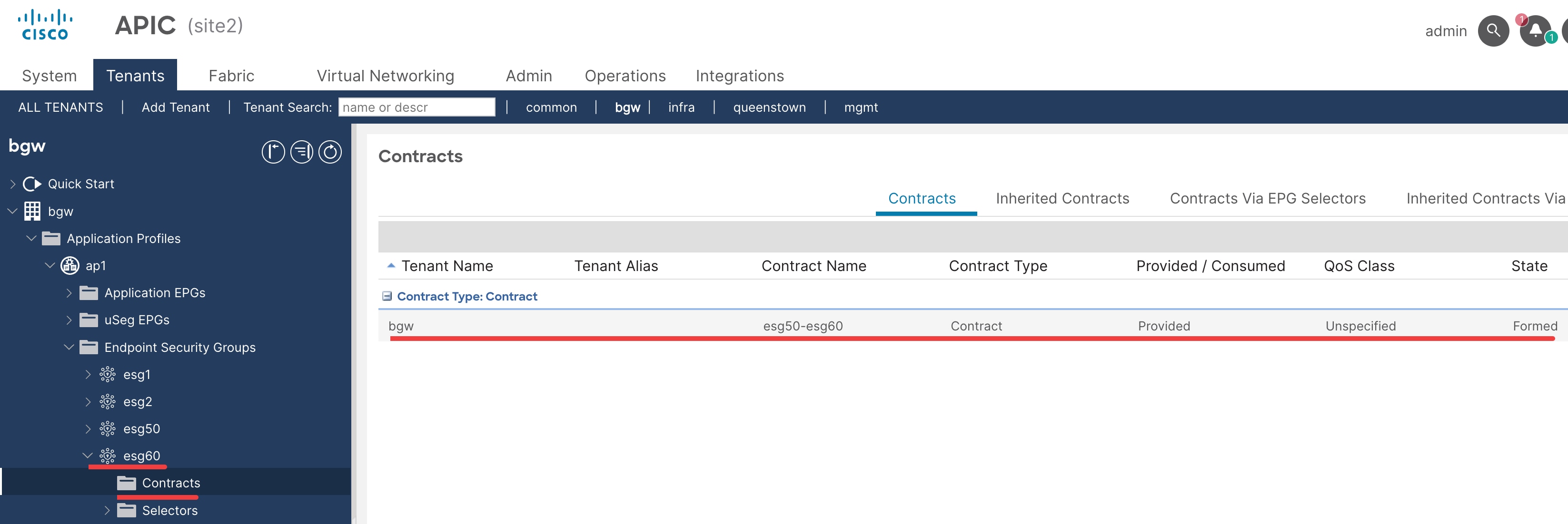
Figure 205. Non-stretch BD multiple ESGs
ACI Site 1 Border Gateways learn the route to 192.168.60.0/24 through BGP EVPN advertised by ACI Site 2 Border Gateway.
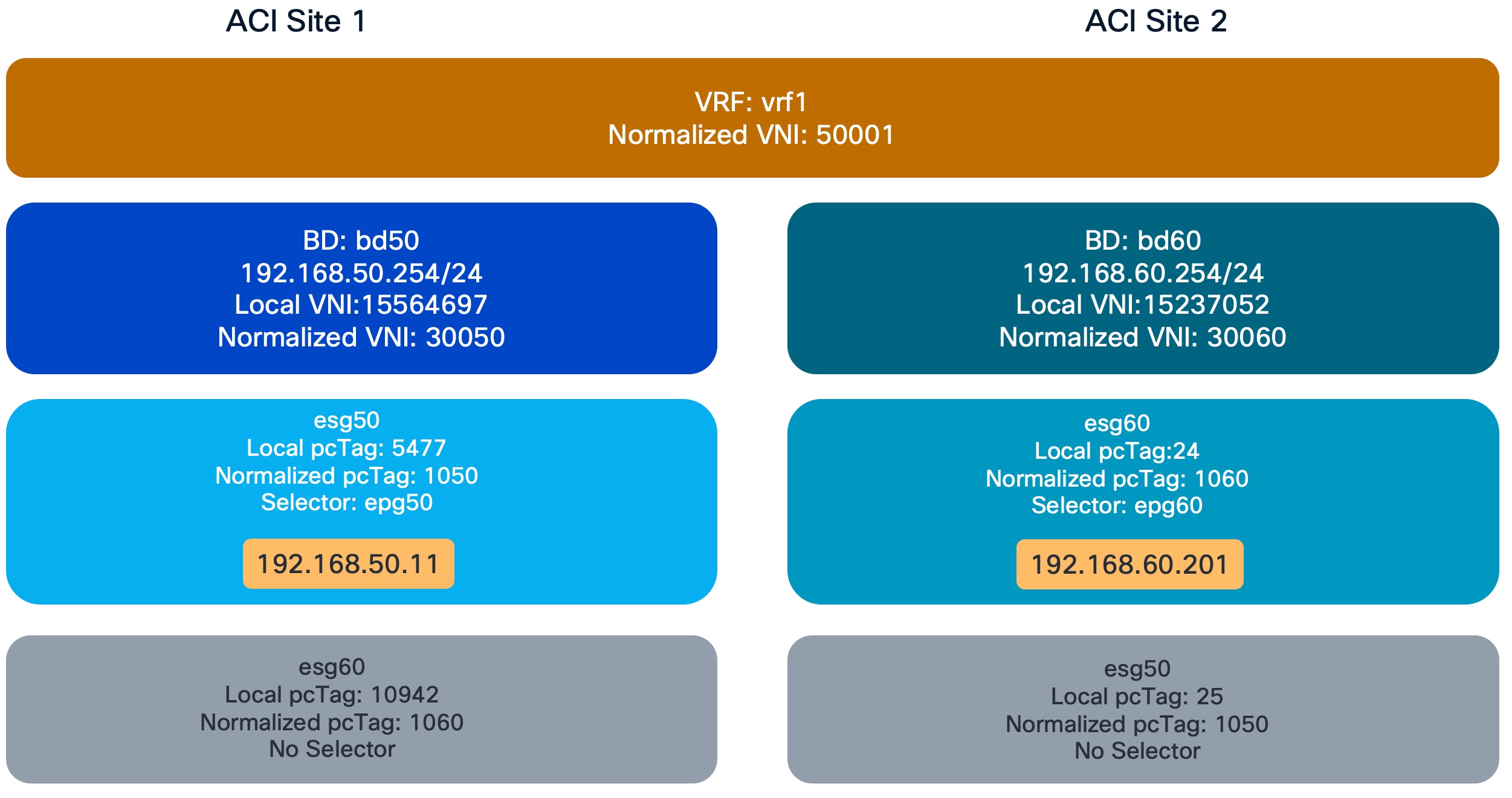
Figure 206. ACI Site 1 Border Gateway learns route 192.168.60.0
The route to 192.168.60.0/24 is then advertised to the ACI Site 1 spine switches through BGP VPNv4 and subsequently reflected to the compute leaf switches.
The compute leaf switches in ACI Site 1 learn the IP subnet route 192.168.60.0/24 with the Border Gateways in the same ACI Pod as the next hops.
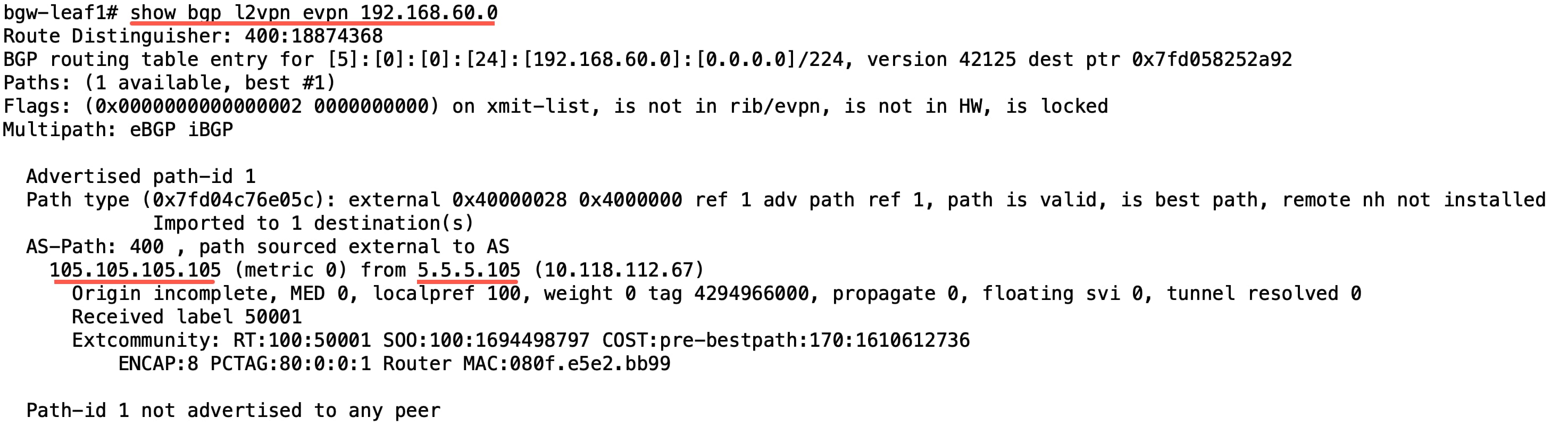
Figure 207. ACI Site 1 Compute leaf learns the route to 192.168.60.0/24
In addition, the ACI Site 1 Border Gateways learn the EVPN Type-2 route for the endpoint 192.168.60.201 located in ACI Site 2. As shown in the output below, pcTag 1060 corresponds to the esg60 Normalized pcTag configured in ACI Site 2.
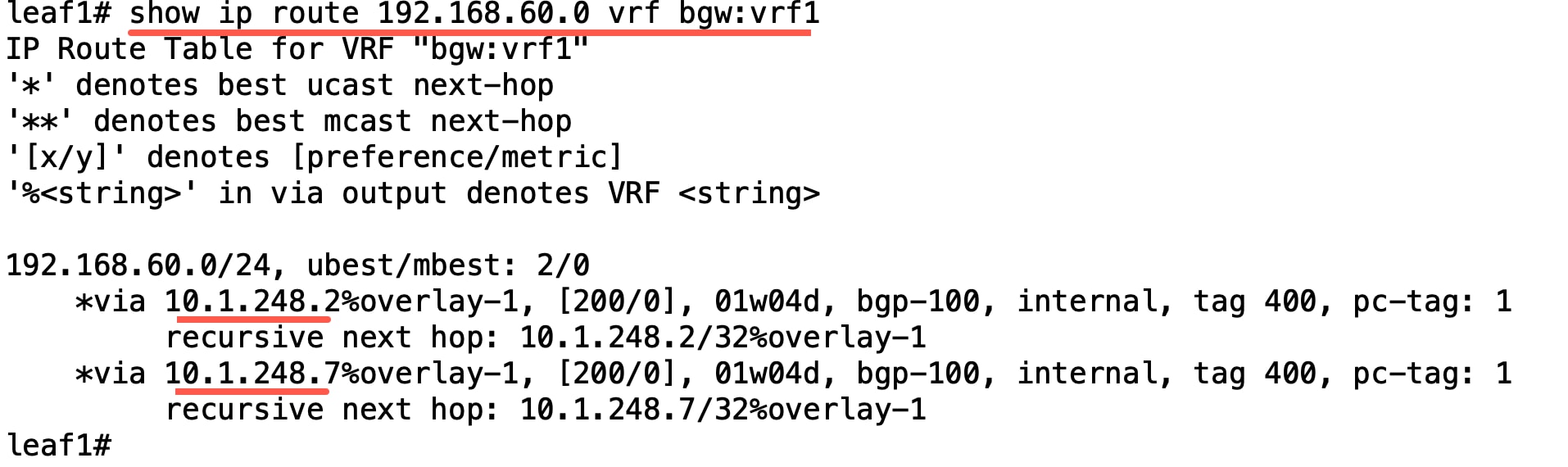
Figure 208. ACI Site 1 Border Gateway learns the EVPN Type-2 route to 192.168.60.201.
The ACI Site 1 Border Gateway programs the host route for the endpoint 192.168.60.201, with the pcTag translated to the local esg60 pcTag value of 10942. The local pcTag value is displayed only when the command is executed in non-vsh mode.
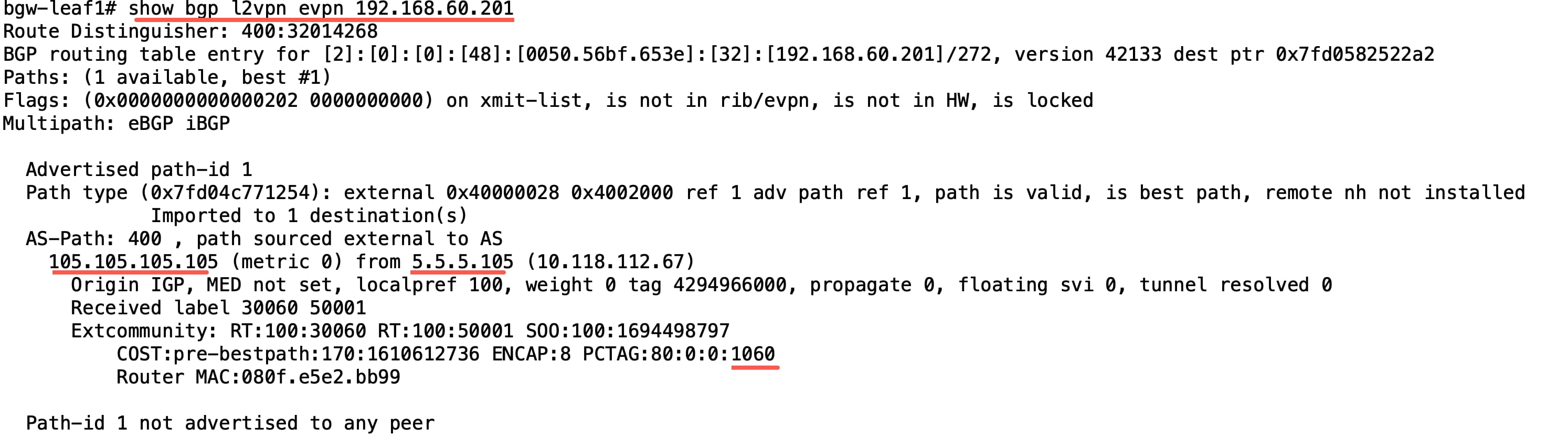
Figure 209. ACI Site 1 Border Gateway program the host route in the routing table with the local site ESG pcTag
Failure scenario (inconsistent normalized pcTag): As shown previously in Figure 211, pcTag 1060 represents the normalized pcTag configured for esg60 in ACI Site 2. If the normalized pcTag for esg60 in ACI Site 2 is changed from 1060 to 10601, the ACI Site 1 Border Gateway still receives the EVPN Type-2 route for endpoint 192.168.60.201 with the updated pcTag value of 10601.
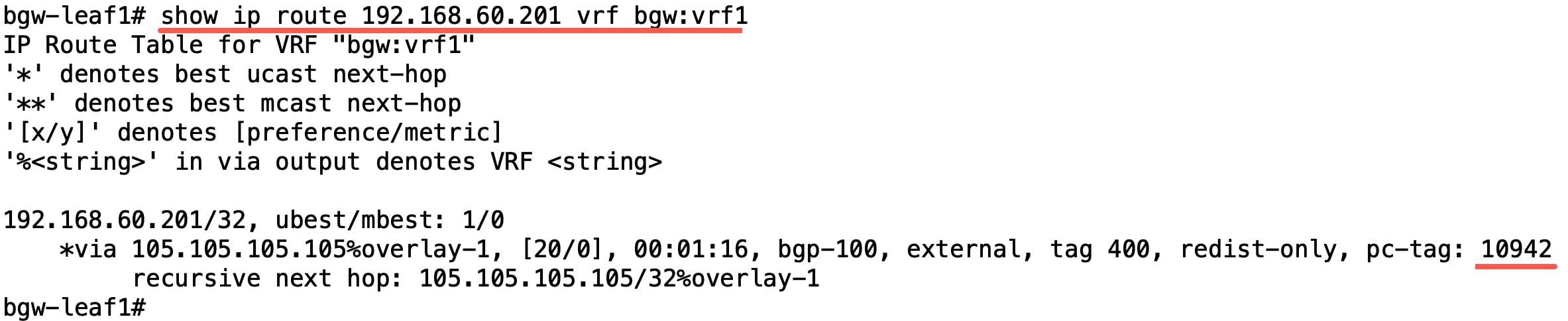
Figure 210. ACI Site 2 Change esg60 Normalized pcTag to 10601
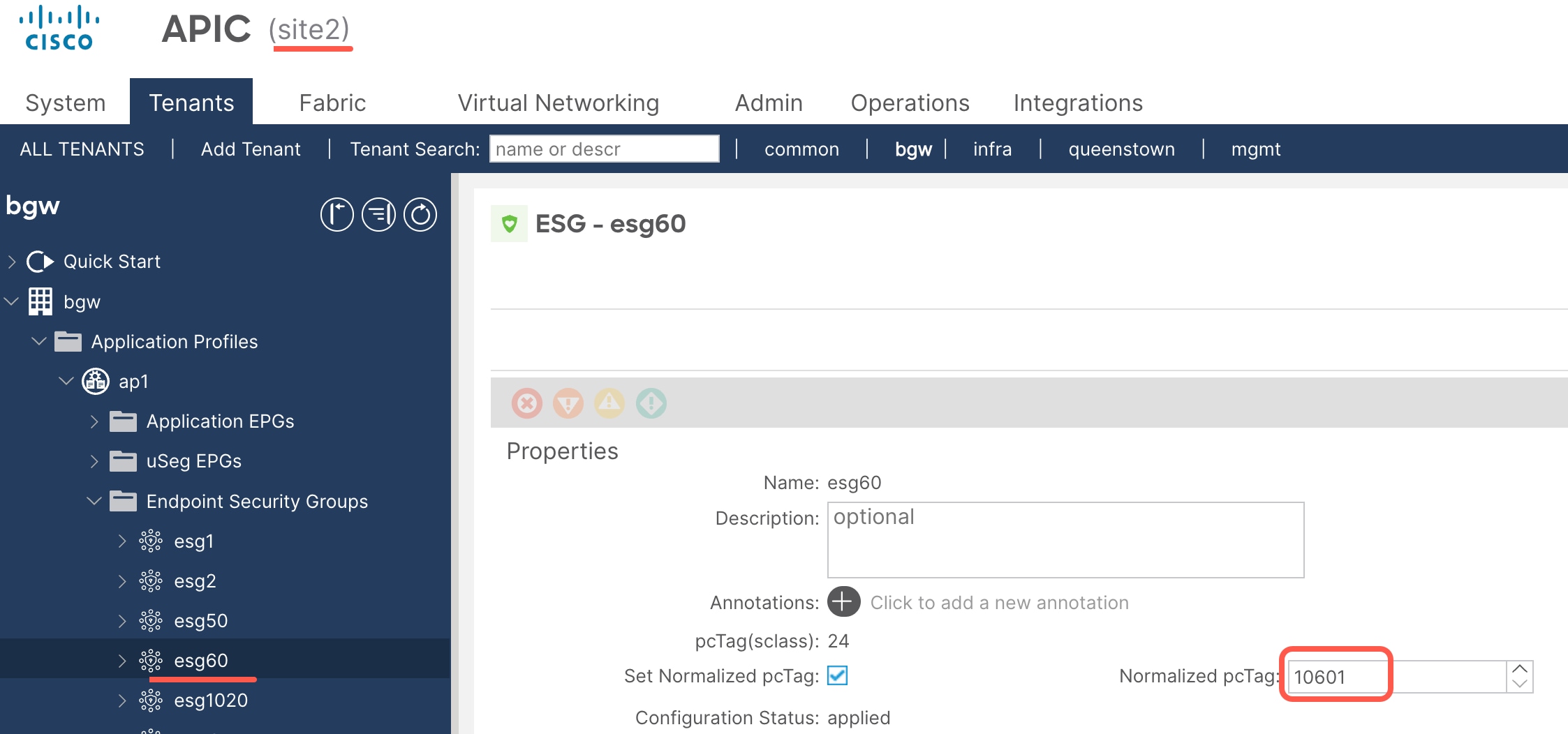
Figure 211. ACI Site 1 Border Gateway receive the EVPN Type-2 route with the updated pcTag 10601
However, because pcTag 10601 does not exist in ACI Site 1, the ACI Site 1 Border Gateway cannot map the received normalized pcTag to a locally defined policy object. As a result, when the Border Gateway programs the host route into the routing table, it uses the reserved pcTag value of 12.
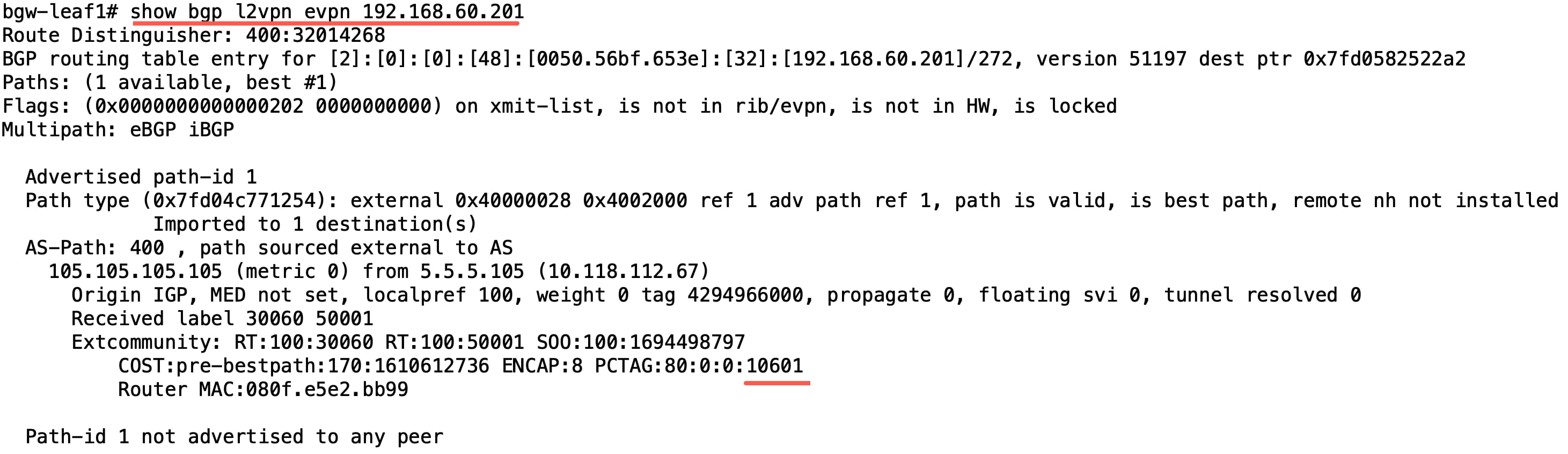
Figure 212. ACI Site 1 Border Gateway use the reserved pcTag of 12 for the unclassified endpoint
The reserved pcTag value of 12 indicates that the endpoint is unclassified from the perspective of ACI Site 1. In other words, ACI Site 1 cannot associate the remote endpoint with any locally recognized policy. Consequently, communication from endpoint 192.168.50.11 in ACI Site 1 to endpoint 192.168.60.201 in ACI Site 2 fails.
This behavior highlights the importance of careful normalized pcTag planning across sites. Consistent pcTag allocation is required to ensure that remote endpoints are correctly classified and that inter-site communication is enforced as intended.
The same verification procedure applies to ACI Site 2, for the sake of brevity , the results are shown below.
ACI Site 2 Border Gateway learns the route to 192.168.50.0/24 through BGP EVPN advertised by ACI Site 1 Border Gateways.
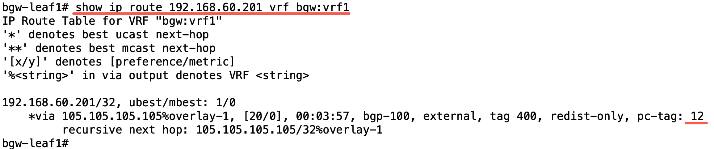
Figure 213. ACI Site 2 Border Gateway receive the EVNP Type-5 route
ACI Site 2 compute leaf switches have the route to 192.168.50.0/24 in its routing table.
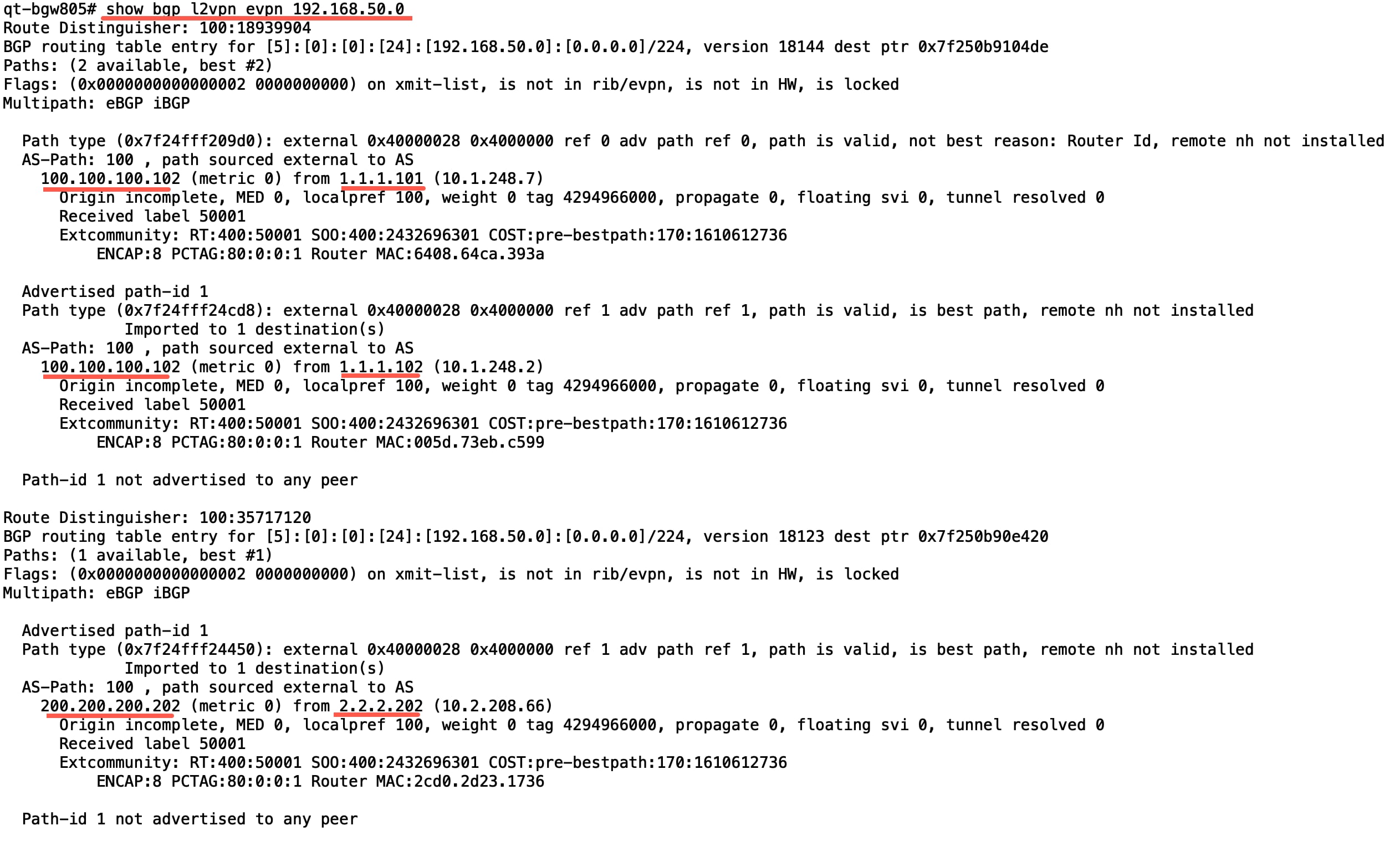
Figure 214. ACI Site 2 Compute leaf route table entry
ACI Site 2 Border Gateway also learns EVPN Type-2 route for the host 192.168.50.11 from ACI Site 1. As shown in the output below, pcTag 1050 corresponds to the esg50 Normalized pcTag configured in ACI Site 1.
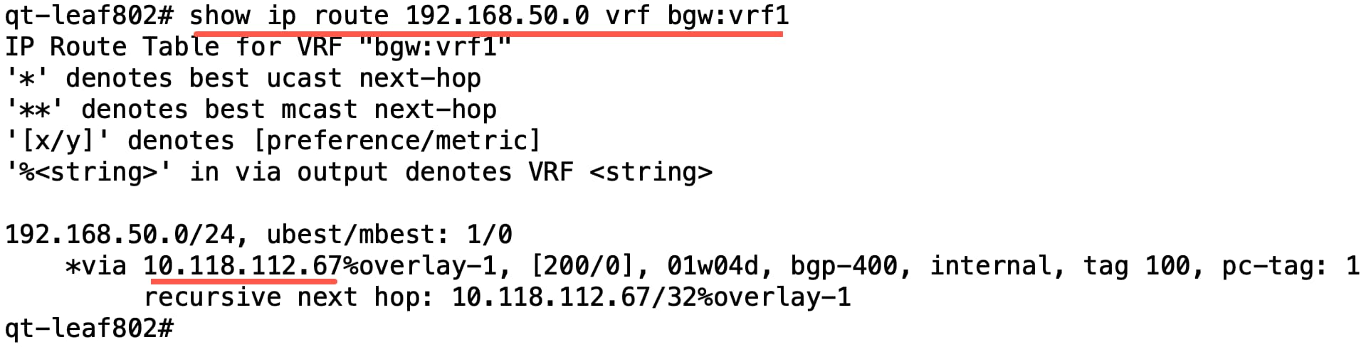
Figure 215. ACI Site 2 Border Gateway learns the EVPN Type-2 route to 192.168.50.11
The ACI Site 2 Border Gateway programs the host route for endpoint 192.168.50.11, with the pcTag translated to the local esg50 pcTag value of 25. The local pcTag value is displayed only when the command is executed in non-vsh mode.
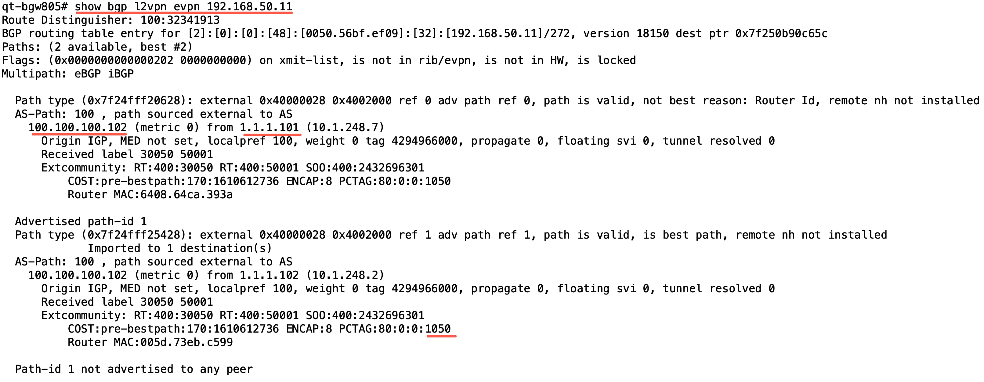
Figure 216. ACI Site 2 Border Gateway program the host route in the routing table with the local site ESG pcTag
Data Plane Verification
In this use case, both esg50 and esg60 are configured on ACI Site 1 and ACI Site 2. However, on ACI Site 1, esg60 has no selectors assigned; and no endpoints belong to esg60 in the site. Similarly, on ACI Site 2, esg50 has no selectors assigned, no endpoints belong to esg50 in the site.
The communication between endpoints in esg50 and esg60, such as between 192.168.50.11(esg50) in ACI Site 1 and 192.168.60.201(esg60) in ACI Site 2 is permitted because a contract is configured between esg50 and esg60 on each site.
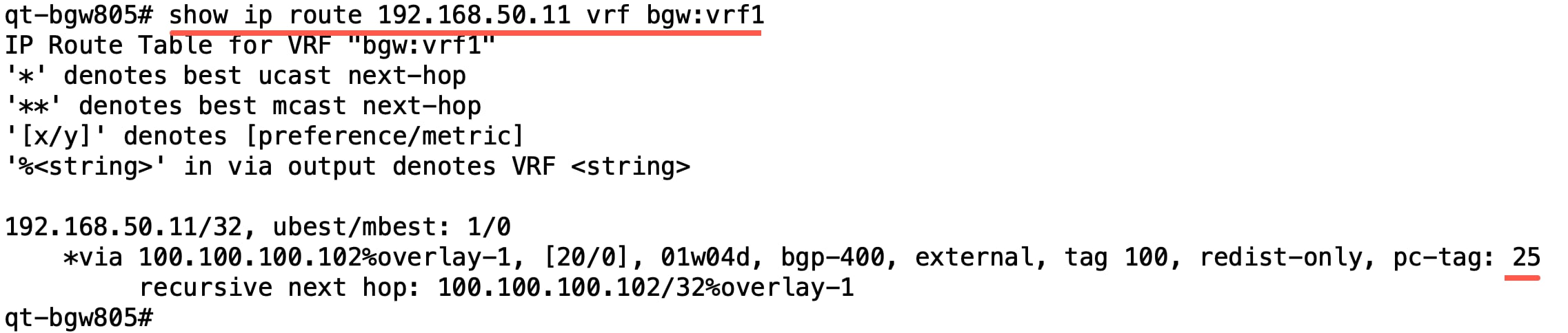
Figure 217. ACI Site 1 esg50 endpoint
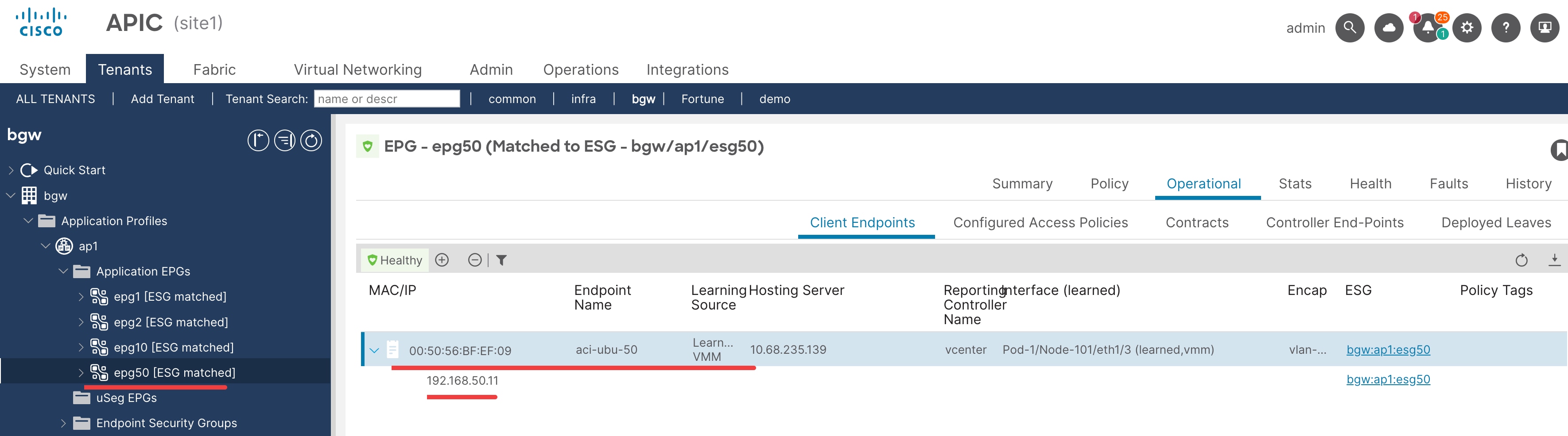
Figure 218. ACI Site 2 esg60 endpoint
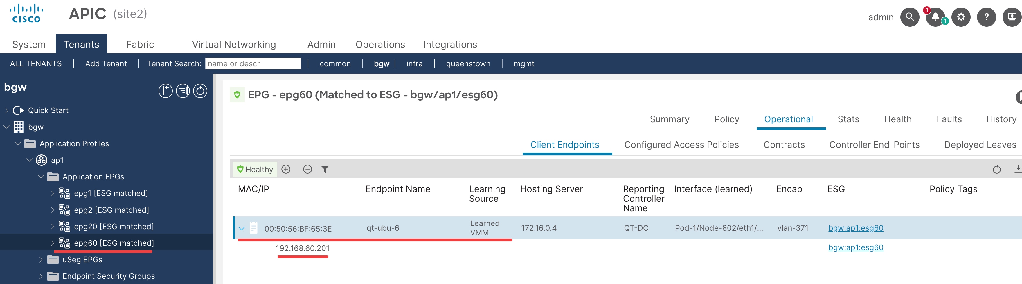
Figure 219. Data plane Inter-Subnet Communication with Non-stretched BDs and Multiple ESGs
An endpoint in esg50 in ACI Site 1 can ping to an endpoint in esg60 in ACI Site 2. The following packet capture was obtained via ERSPAN traffic from ISN device. The packet capture of the ICMP request from EP-50 to EP-60 confirms that the Layer 3 (VRF) Normalized VNI is used in the VXLAN header for inter-site data plane forwarding.
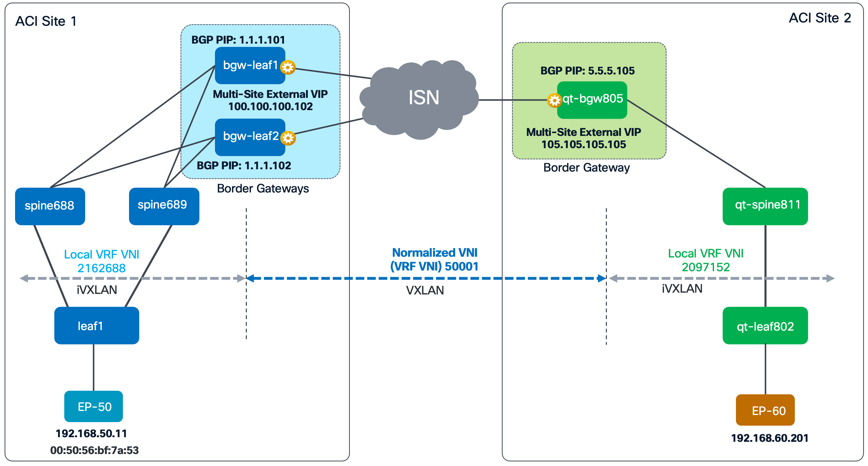
Figure 220. ICMP request from EP-50 (192.168.50.11) to EP-60 (192.168.60.201)
The packet capture of the ICMP reply from EP-60 to EP-50 confirms that the Layer 3 (VRF) Normalized VNI is used in the VXLAN header for inter-site data plane forwarding.
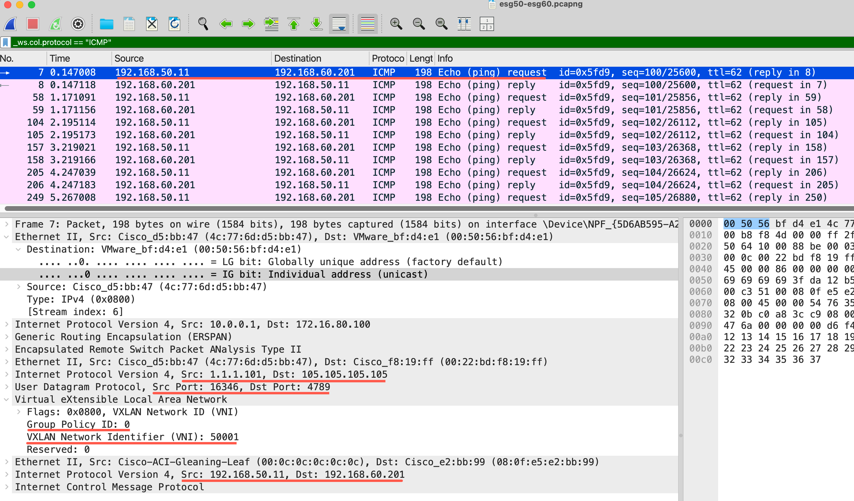
Figure 221. ICMP reply from EP-60 (192.168.60.201) to EP-50 (192.168.50.11)
From a policy enforcement location perspective, this use case is identical to Use Case 3: Inter-Subnet Communication Non-stretched BDs Single ESG.
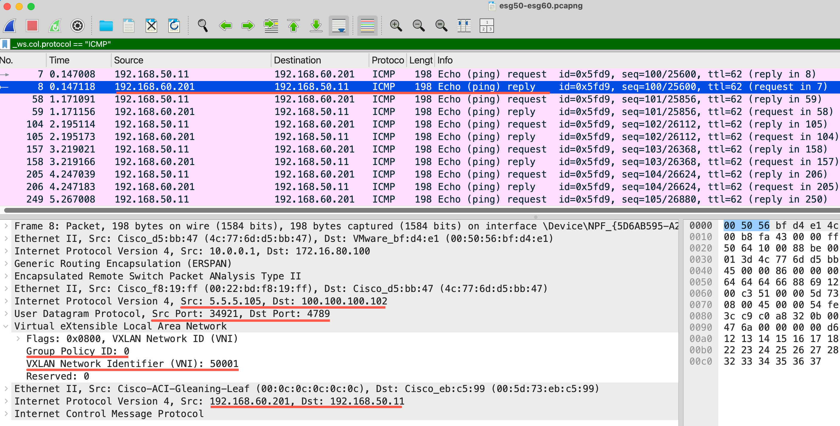
Figure 222. Inter-ESG Inter-Subnet communication policy enforcement
Use Case 5: North-South Communication Across ACI Sites with Stretched BD
This use case is North-South communication from an endpoint in ACI Site 1 to an external endpoint located behind the L3Out of ACI Site 2, and vice versa, from an endpoint in ACI Site 2 to an external endpoint located behind the L3Out of ACI Site 1.
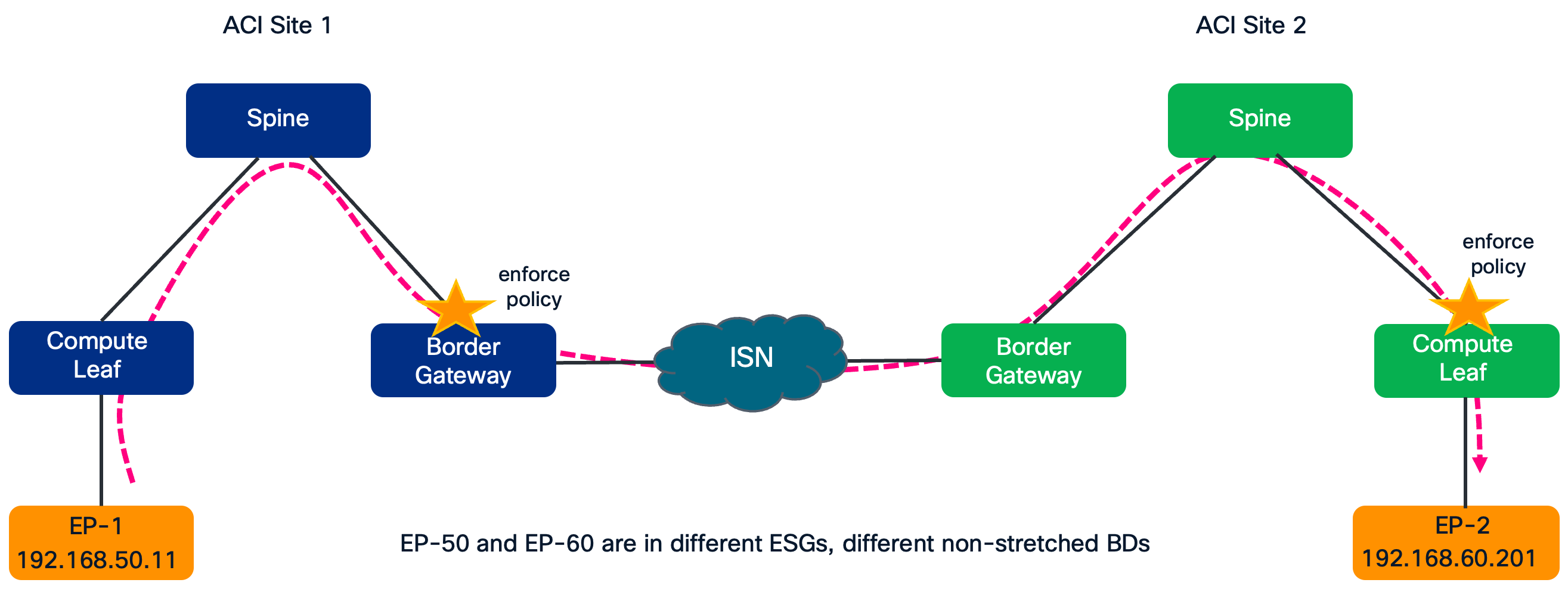
Figure 223. North-South Communication across ACI Sites
In this use case, the new feature starting from ACI release 6.1(4) is used to classify external prefixes to a specific ESG by using external subnet selectors. So that it will be a contract between ESGs from contract configuration perspective, which is like other use cases.
For more detail, please refer to this link https://www.cisco.com/c/en/us/td/docs/dcn/aci/apic/6x/security-configuration/cisco-apic-security-configuration-guide-61x/endpoint-security-groups-61x.html
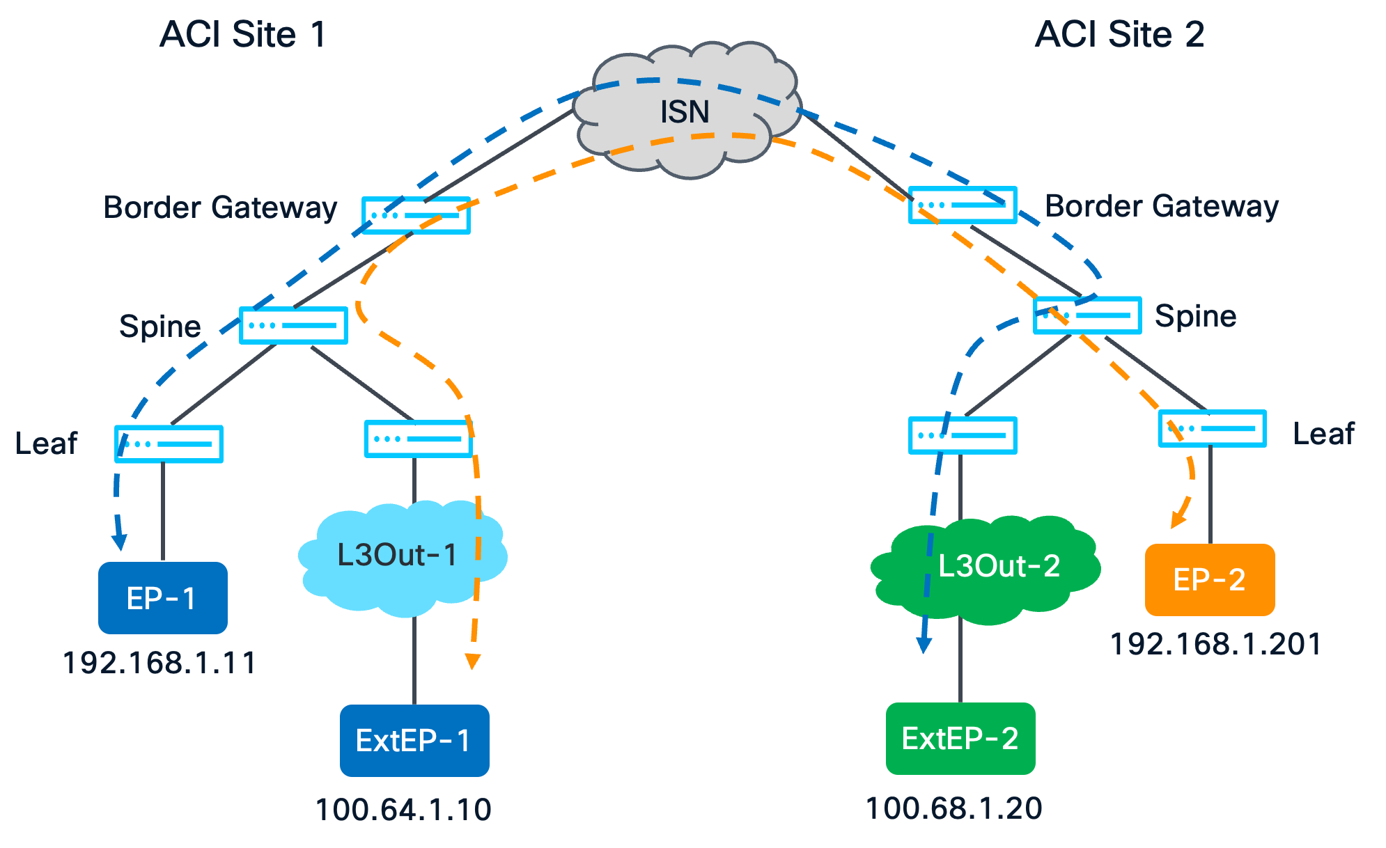
Figure 224. North-South Communication across ACI Sites
It is assumed that readers are familiar with ACI fundamental concepts such as L3Out and able to configure ACI L3Out.
Considerations for Endpoint Security Groups (ESG) with External Subnet Selectors
When implementing Endpoint Security Groups (ESGs) using External Subnet Selectors to classify L3Out traffic, network administrators must adhere to specific configuration guidelines to ensure deterministic traffic classification and maintain data plane connectivity. These considerations are applicable to all deployment scenarios involving L3Out connectivity, encompassing both local North-South traffic flows and cross-site communication.
1. Overlapping and Exact Match External Subnet Selectors
To ensure predictable classification, the configuration of External Subnet Selectors must be unique across all ESGs within the same VRF. Also, the configured external subnet selectors should always exactly match the external prefixes learned via the L3Out connection.
Though Cisco APIC allows the configuration of overlapping prefixes (e.g., 100.64.0.0/24 in ESG ext-1 and 100.64.0.0/16 in ESG ext-2) to classify routes received from the external network on the L3Out, this practice is strongly discouraged. Due to current implementation specifics within the ACI fabric, the use of overlapping prefixes may result in non-deterministic or incorrect classification. The same considerations apply to the specific use case where specific prefixes and a default-route are learned via the L3Out. If an external subnet selector is defined to classify the default route 0.0.0.0/0, the same non-deterministic or incorrect classification issue may arise, since such route represents a prefix that overlaps (i.e. “covers”) all more specific prefixes.
Note: Always ensure that External Subnet Selector prefixes do not overlap across ESGs to maintain stable policy enforcement. This is a current requirement in ACI; however, a future ACI release is planned to address this issue. The paper will be updated accordingly once the enhancement is available.
The figure below illustrates an example where communication from ESG esg1 to ESG ex-1 may break when a new ESG ext-1-a with an overlapping External Subnet Selector is introduced.
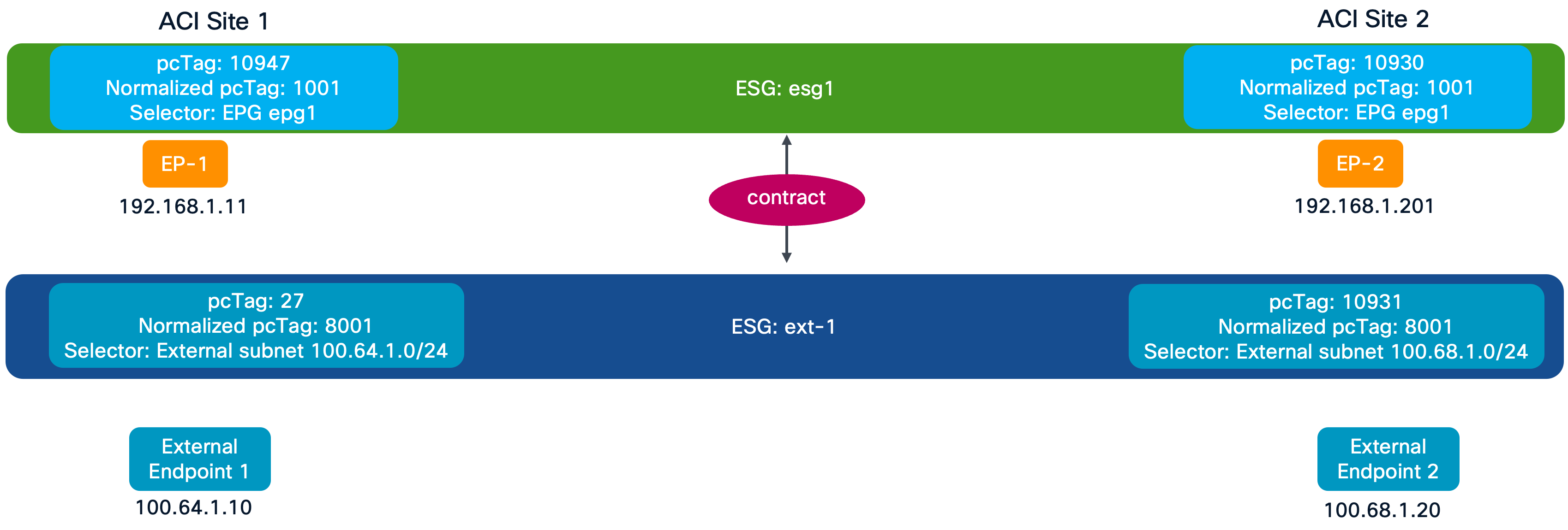
Figure 225. Communication is broken due to a mismatch between ESGs with overlapping External Subnet Selectors
2. Alignment Between Selectors and the Routing Table Prefixes
As explained in the point above, for successful classification, an External Subnet Selector must correspond to a specific prefix present in the routing table (RIB) of the L3Out (e.g. the prefix is learned via the L3Out) and an exact prefix matching is required in the External Subnet Selector.
Defining a more specific prefix (e.g., 100.64.1.0/24) as a selector when only the default route (0.0.0.0/0) is learned via the L3Out will result in a failure of data plane communication between the remote site endpoint (EP-2 in Site 2) and external endpoint in Site 1 (ExtEP-1 in Site 1).
The figure below illustrates the connectivity failures that occur when the External Subnet Selector does not align with the received routes. In this scenario, traffic from EP-2 to ExtEP-1 is dropped by the Border Gateway in Site 2. This occurs because the Border Gateway lacks a specific pcTag mapping for the 100.64.1.0/24 external subnet where ExtEP-1 resides (since that prefix was never learned via the L3Out of Site 1 and therefore could not be propagated toward Site 2 via EVPN control plane). Instead, the Border Gateway only learns via EVPN the 0.0.0.0/0 default route, which is associated with the pcTag 12, the reserved tag for unclassified destinations (this is because in this example, an External Subnet Selector for 0.0.0.0/0 was not defined in Site 1). Consequently, the Border Gateway treats ExtEP-1 as an unclassified endpoint, resulting in a policy drop.
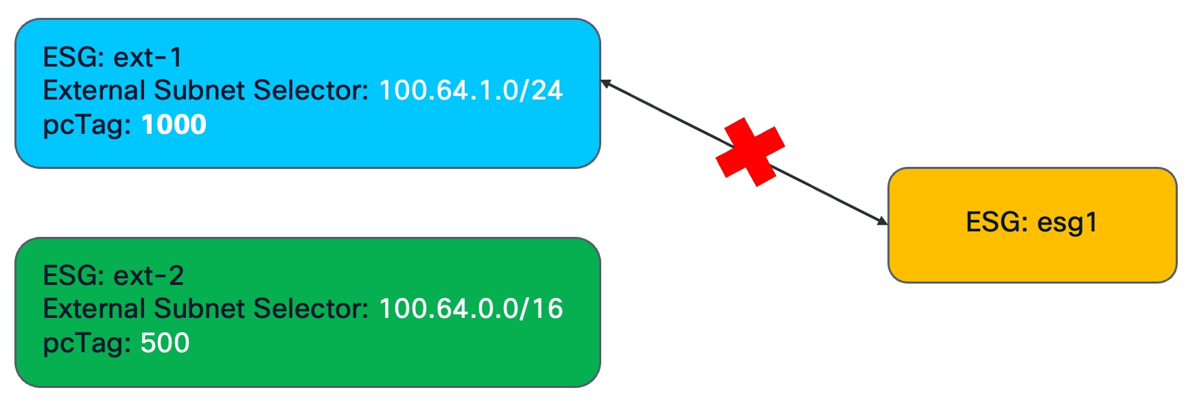
Figure 226. Cross-site data plane broken due to a mismatch between the External Subnet Selector and the received prefix.
The same logic applies to the supernet use case, where an external device advertises only 100.64.0.0/16 to Site 1, and Site 1 ESG ext-1 configures the External Subnet Selector as 100.64.1.0/24.
Configure ACI L3Out, External EPG, ESG with External Subnet Selector
In this use case, BGP is used for the routing protocol between the ACI border leaf switches and the external router. Although OSPF and static routing are also valid options, BGP is the preferred option. An external EPG is required to deploy IP interfaces and BGP configuration on the border leaf switches based on the L3Out configuration, but no external EPG subnet configuration is required because the classification of external prefixes will be done by external subnet selectors. The figures below show the configuration examples in ACI Site 1.
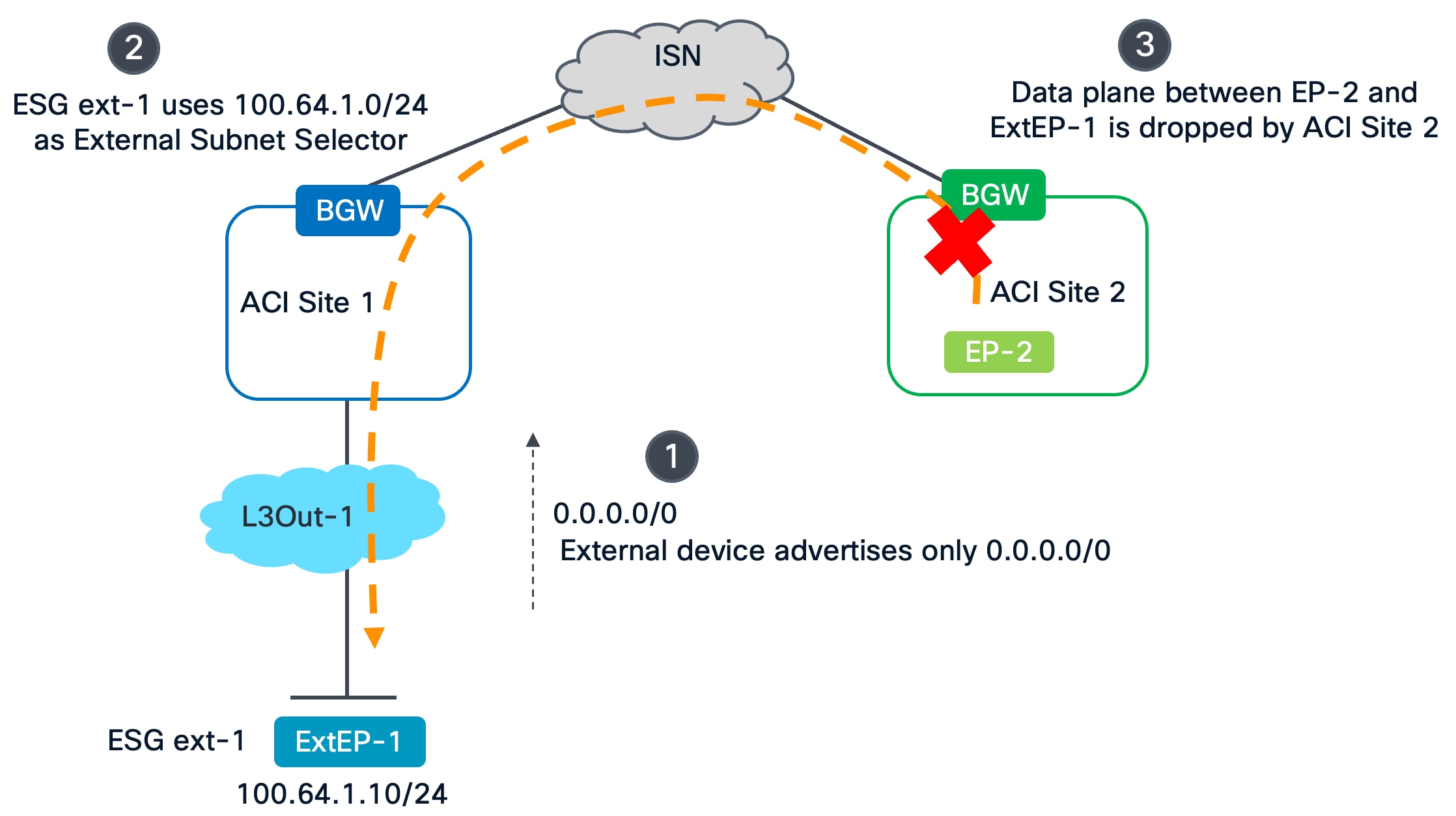
Figure 227. ACI Site 1 L3Out and External EPG
Create ESG ext-1 and set normalized pcTag to 8001. The same configuration will be applied to ACI Site 2 later.
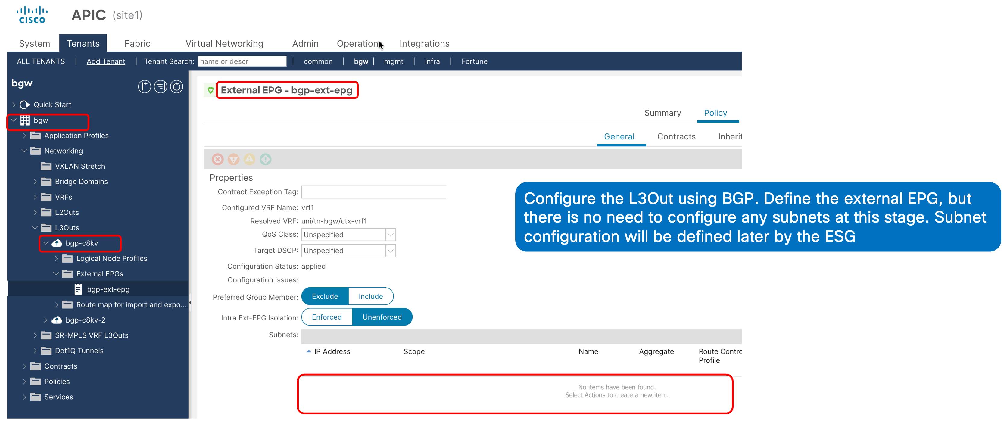
Figure 228. ACI Site 1 ESG ext-1
Define External Subnet Selector for ESG ext-1. This step is crucial: make sure to select “External Subnet Selector” as the selector for ESG ext-1, specify the subnet 100.64.1.0/24 as the external subnet in the selector.
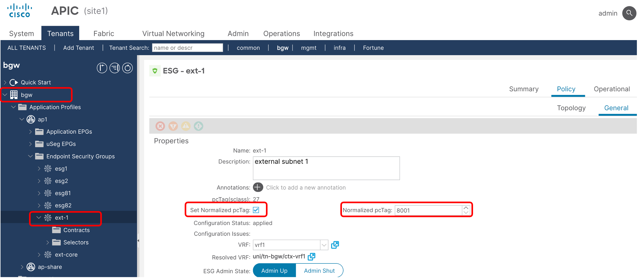
Figure 229. ACI Site 1 ESG ext-1 with external subnet selector
Create a contract “esg-to-ext-1” and configure a filter as needed; in this example, the contract has a filter to allow all IP traffic. Apply this contract between esg1 and ext-1, ensuring that one side is set as the consumer and the other as the provider.

Figure 230. ACI Site 1 – ESG esg1 contract consumer
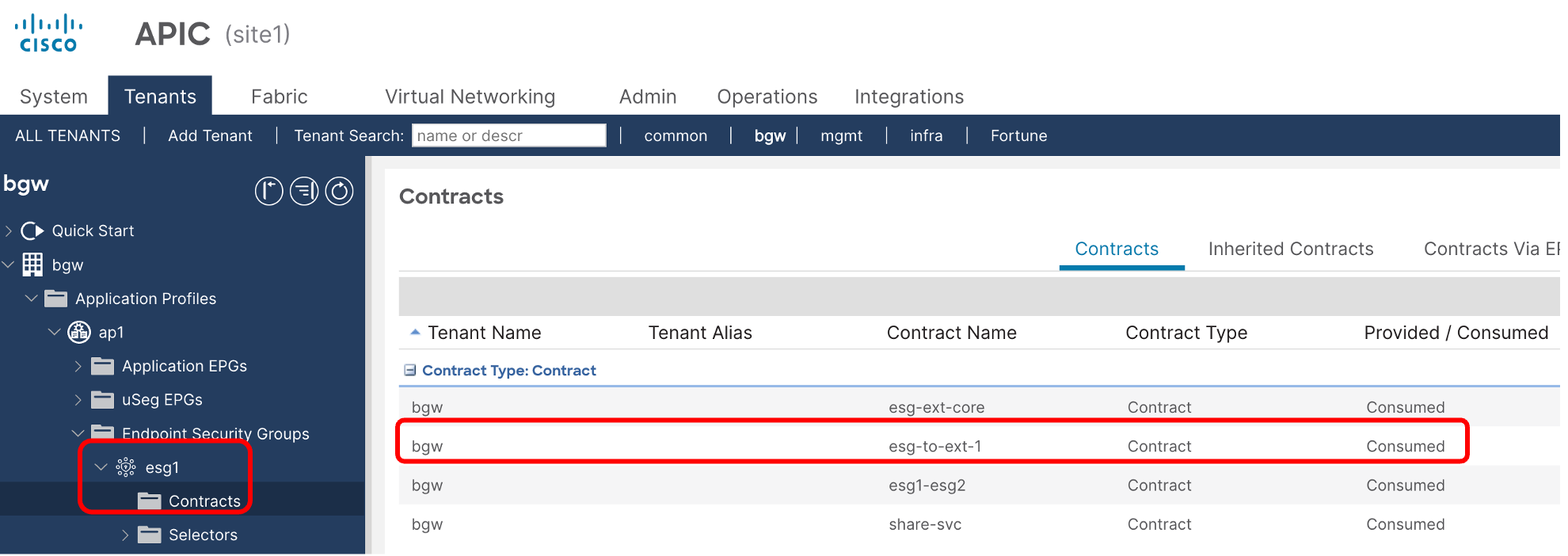
Figure 231. ACI Site 1 ESG ext-1 contract provider
Similar to the configuration shown for ACI Site 1, the following figures illustrate configuration examples for ACI Site 2. Begin by configuring an L3Out and creating an external EPG without any associated subnet. Note that at least one L3Out EPG is required to deploy a routing protocol and configure related interface parameters on the leaf switches. Although the L3Out EPG functions as a security construct similar to other EPGs, it does not represent the routing protocol configuration itself. For detailed information, please refer to the Cisco ACI Fabric L3Out White Paper at https://www.cisco.com/c/en/us/solutions/collateral/data-center-virtualization/application-centric-infrastructure/guide-c07-743150.html
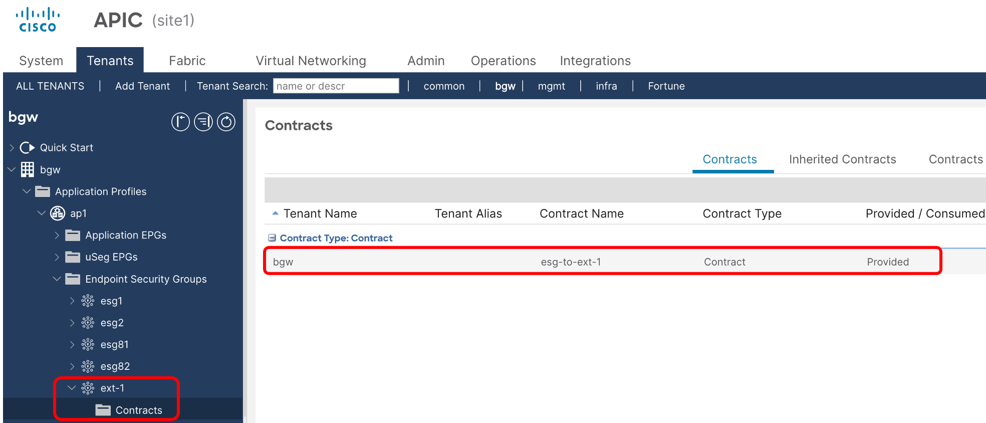
Figure 232. ACI Site 2 L3Out and External EPG
Create ESG ext-1 and set the normalized pcTag to 8001.
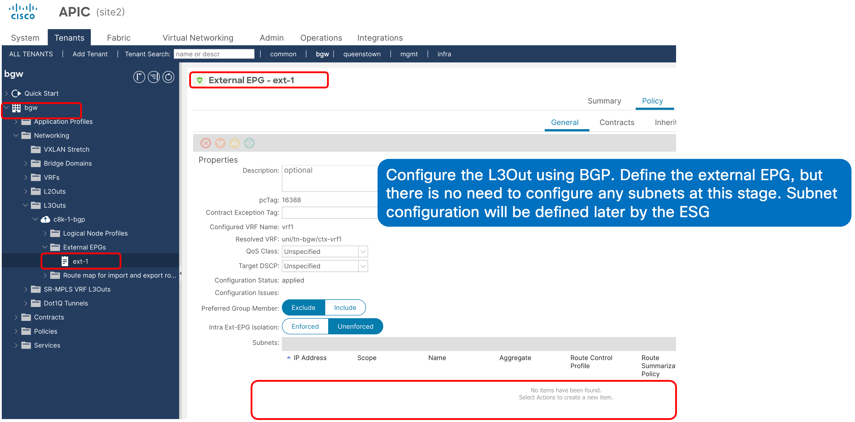
Figure 233. ACI Site 2 ESG ext-1
Define External Subnet Selector for ESG ext-1. This step is crucial: make sure to select “External Subnet Selector” as the selector for ESG ext-1, specify the subnet 100.68.1.0/24 as the external subnet in the selector.
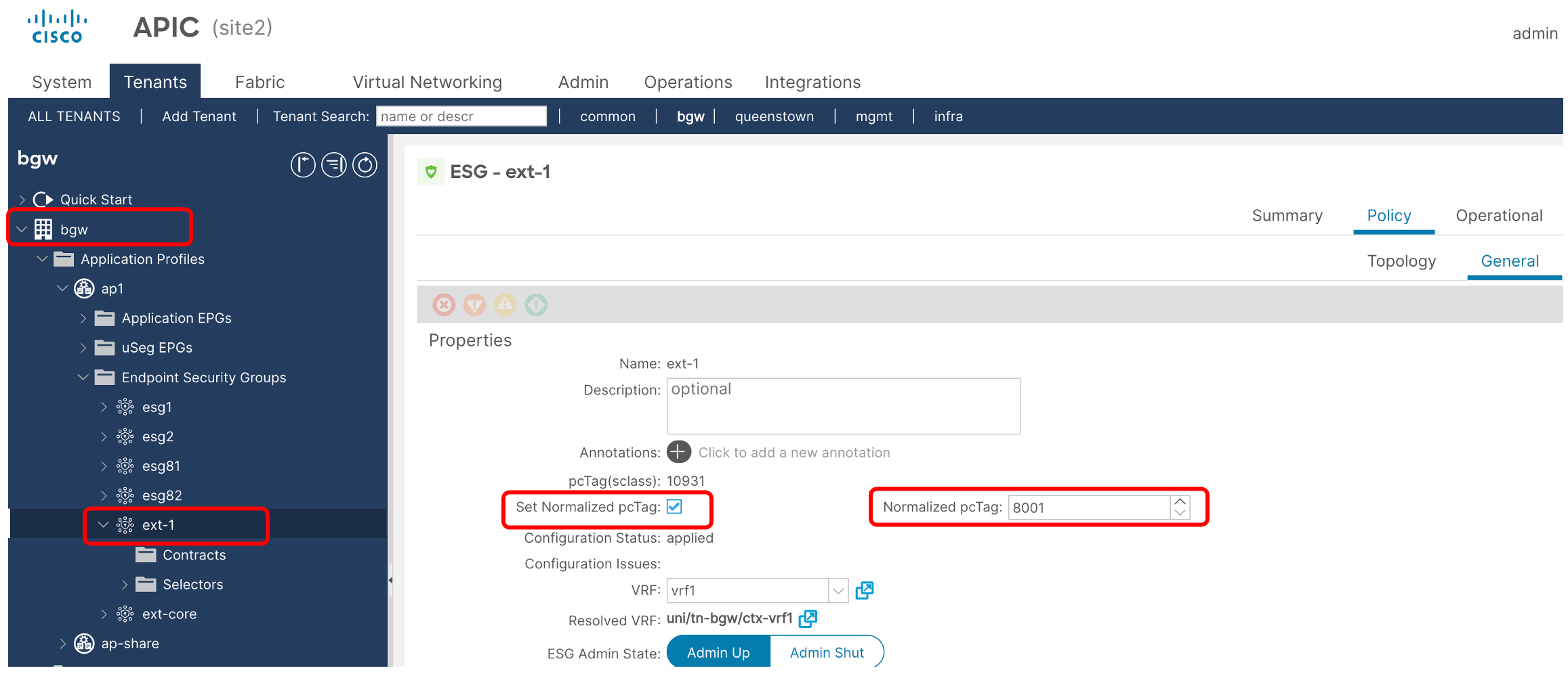
Figure 234. ACI Site 2 ESG ext-1 with external subnet selector
Create a contract “esg-to-ext-1” and configure a filter as needed; in this example, the contract has a filter to permit all IP traffic. Apply this contract between ESG1 and ext-1, ensuring that one side is set as the consumer and the other as the provider.
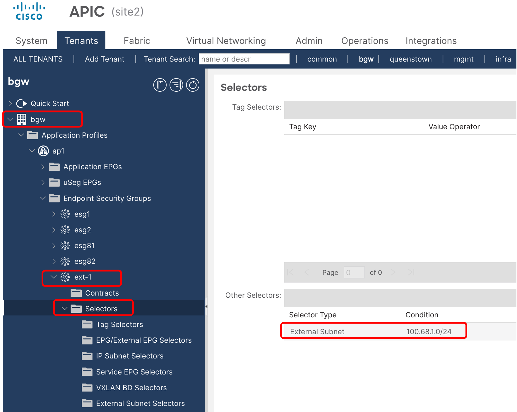
Figure 235. ACI Site 2 ESG esg1 contract consumer
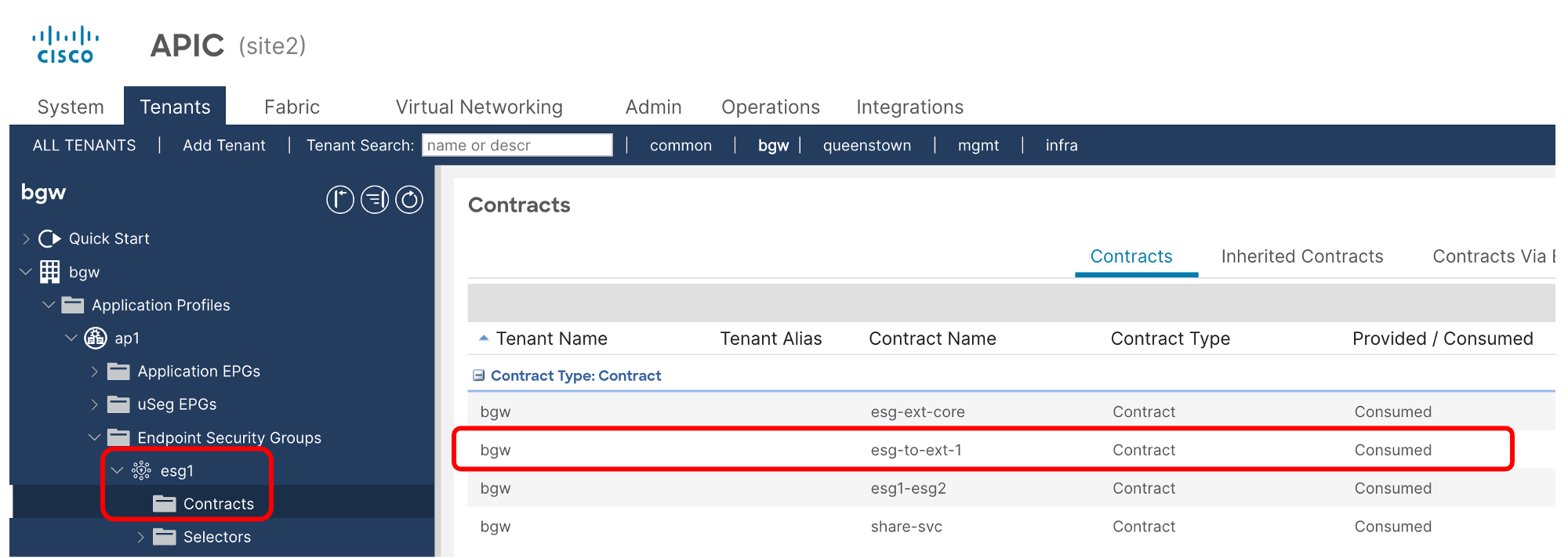
Figure 236. ACI Site 2 ESG ext-1 contract provider
Control Plane Verification
The figure below shows the parameters used for the control plane verification example in this section.
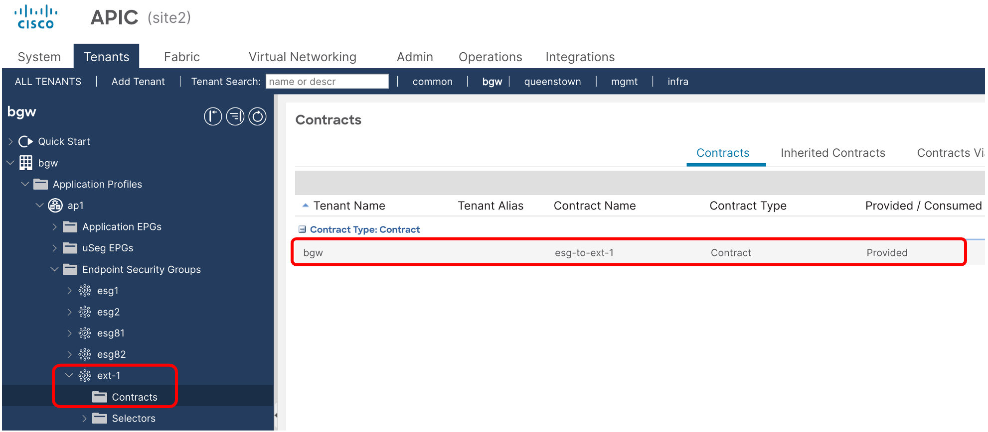
Figure 237. EVPN Type 5 Route exchange across ACI Sites
Note that bd1 (subnet 192.168.1.254/24) is stretched bridge domains, as defined in the section Tenant-Based Line Configuration.
The block diagram below illustrates the EVPN Type-5 route exchange process between ACI sites. While the diagram depicts the route advertisement from ACI Site 1 to ACI Site 2, the same logic applies to advertisement from ACI Site 2 to ACI Site 1.
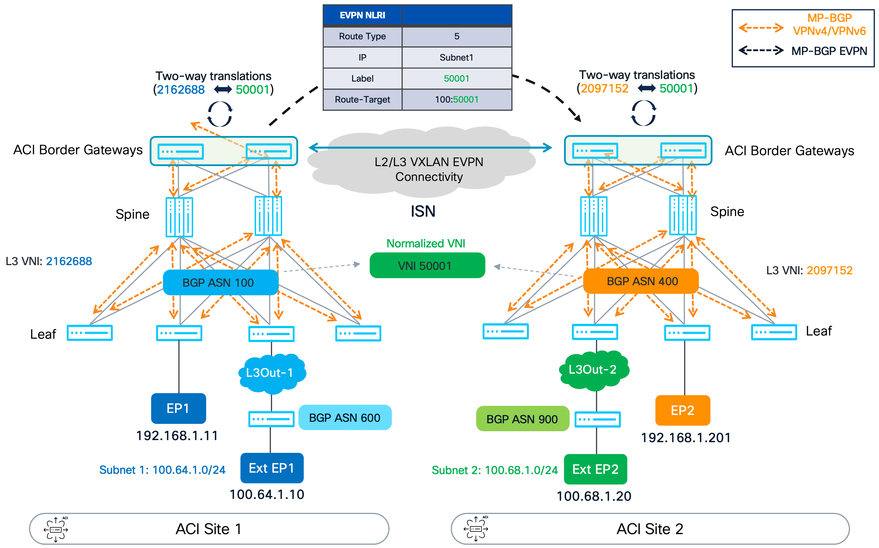
Figure 238. EVPN Type-5 update from ACI Site 1 to Site 2
ACI Site 1 border leaf learns the route from the external device; it is a general behavior, not specific to Multi-Site design. In this example, leaf1 serves a dual role as both a border leaf and a compute leaf.
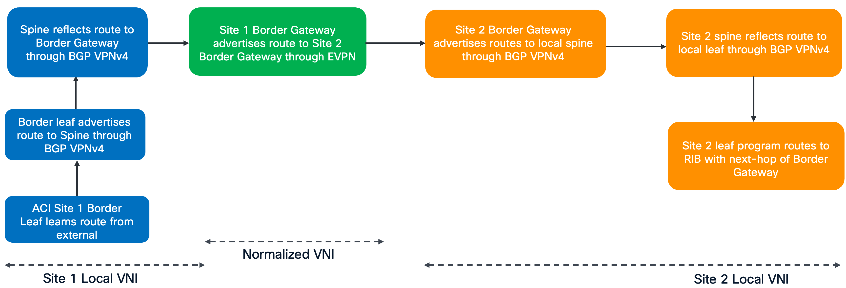
Figure 239. ACI Site 1 Border Leaf learns external route
The border leaf assigns the local pcTag to the external subnet based on the external subnet selector for ESG. In this example, ESG ext-1 is assigned a local pcTag of 27.
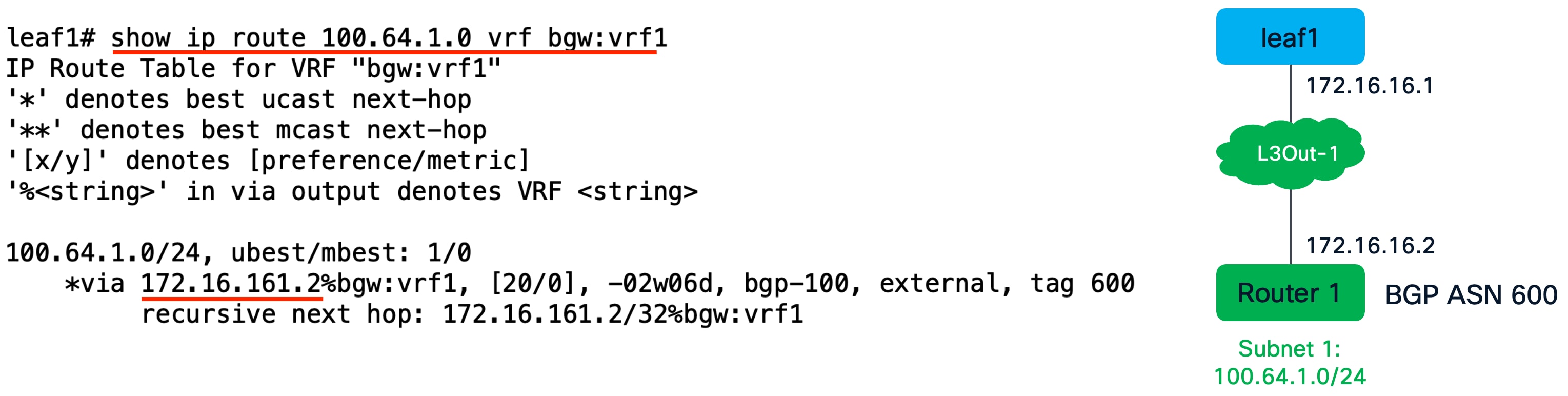
Figure 240. ESG ext-1 pcTag
The external subnet route, along with its associated local pcTag of 27, is carried via VPNv4 from the border leaf to the Border Gateway in the same ACI site. Specifically, the border leaf advertises the route to the spine, which in turn reflects the route to the other switches including Border Gateways. The Border Gateways receive the route via VPNv4, identifying the border leaf PTEP (10.1.248.3) as the next hop.
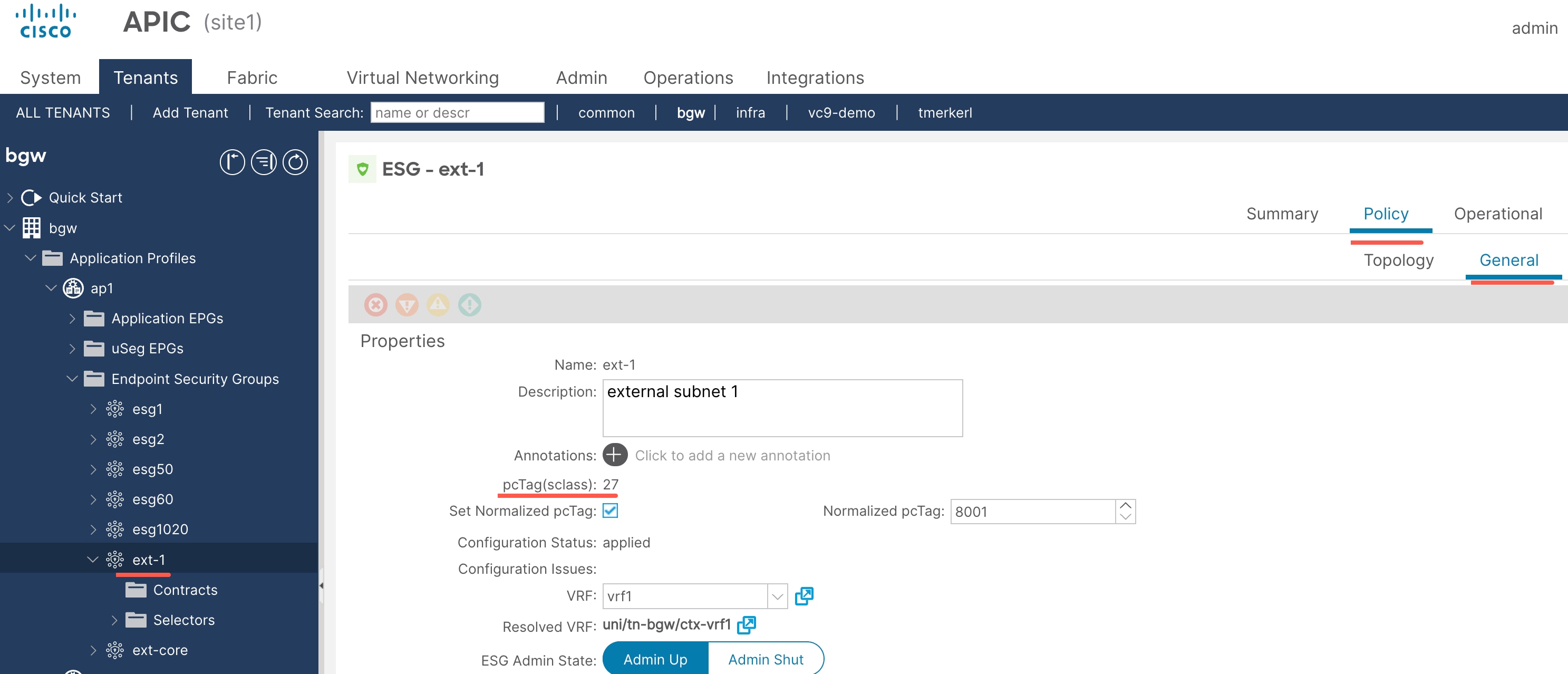
Figure 241. ACI Site 1 Border Gateway learns external route
The ACI Site 1 Border Gateways advertise the route 100.64.1.0/24 to the ACI Site 2 Border Gateways via BGP EVPN. This advertised route can be verified in the BGP EVPN output, as shown in the screenshot below. As highlighted in the output, the value 27 represents the local pcTag carried from the ACI Site 1 Border Leaf. The IP address 5.5.5.15 is the loopback interface IP Address of ACI Site 2 Border Gateway.
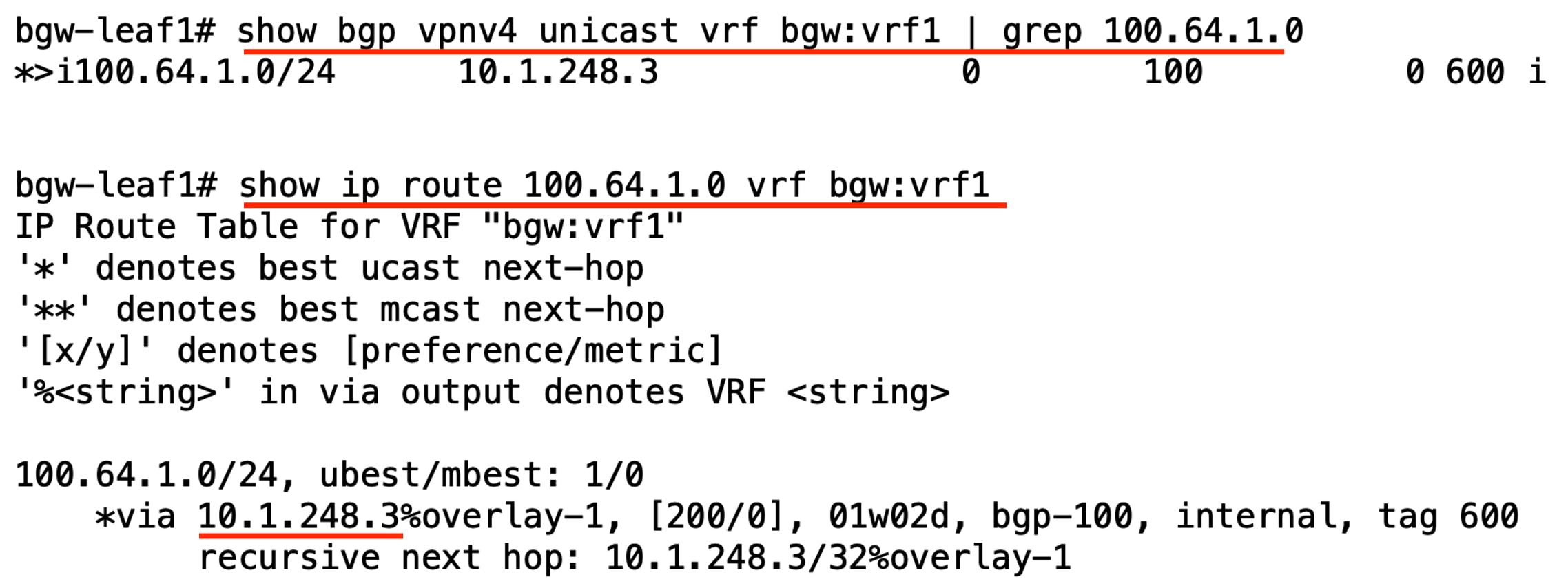
Figure 242. ACI Site 1 Border Gateway advertises EVPN Type-5
It is important to note that when advertising the route to another site, the ACI Site 1 Border Gateway uses the normalized pcTag value of 8001 (configured at ESG ext-1). The normalized pcTag value of 8001 can also be observed on the receiving side, which is the ACI Site 2 Border Gateway. Now on ACI Site 2 Border Gateways, EVPN Type-5 route is received, which verifies the route is advertised properly.
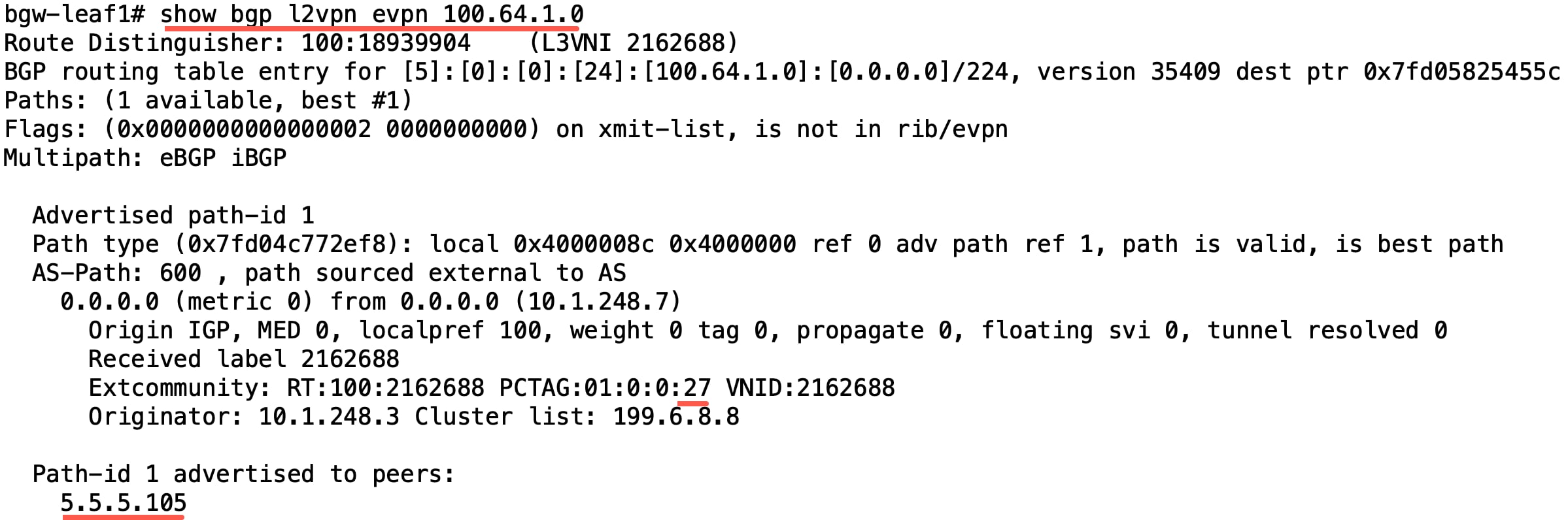
Figure 243. ACI Site 2 Border Gateway receives EVPN Type-5 route
As shown above, the pcTag value (8001) is carried within the EVPN Type-5 update. This value represents the normalized pcTag for the ESG ext-1 configured on ACI Site 1. The IP address 100.100.100.102 is External Data Plane IP, also known as Multi-Site External VIP of Border Gateway in Pod-1 in ACI Site 1. The value 50001 in “Received label 50001” indicates that the border gateway receives the EVPN route in VNI 50001, which is the normalized VNI of VRF vrf1 used in both ACI sites.
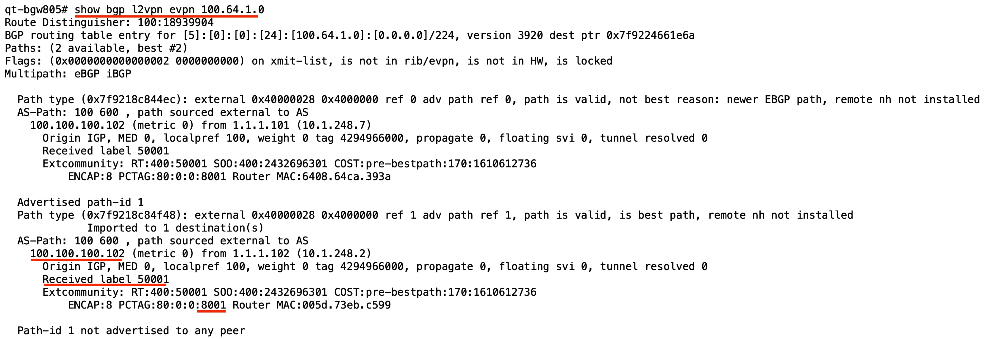
Figure 244. ACI Site 1 ESG ext-1
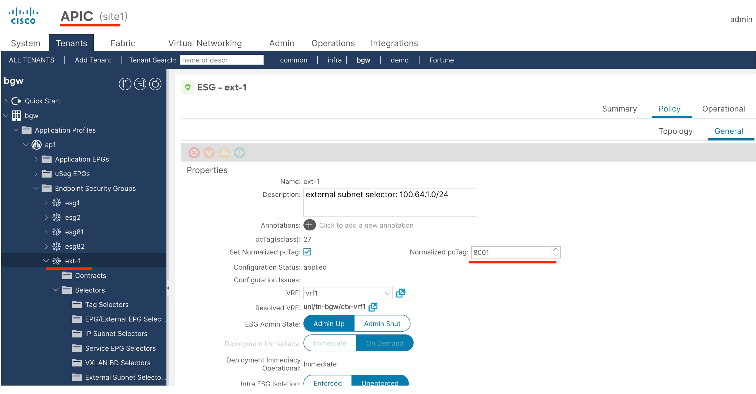
Figure 245. ACI Site 1 Border Gateway Set
ACI Site 2 Border Gateway then imports the route to 100.64.1.0/24 from EVPN to BGP VPNv4.
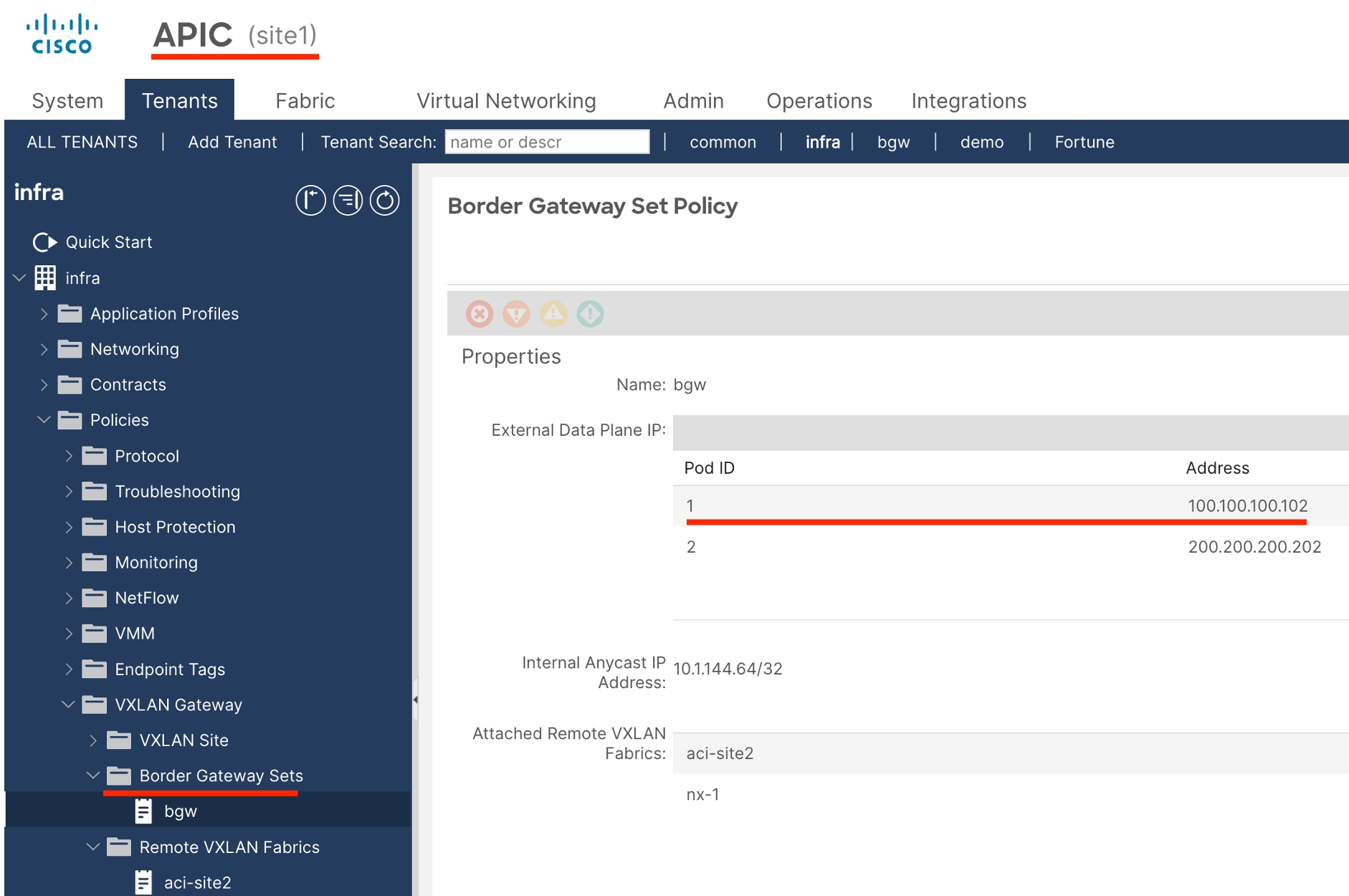
Figure 246. ACI Site 2 Border Gateway imports the EVPN route to VPNv4
Note that 100 is ACI Site 1 BGP ASN, 600 is BGP ASN of the external router connecting to ACI Site 1 border leaf. ACI Site 2 Border Gateway installs the route to its routing table.
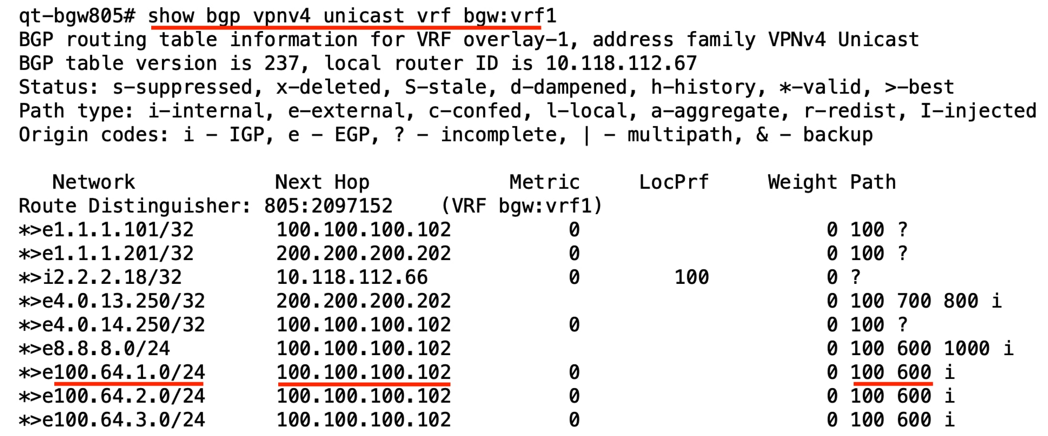
Figure 247. ACI Site 2 Border Gateway routing table
100.100.100.102 is ACI Site 1 Pod 1 External Data Plane IP also known as Multi-Site External VIP. The value 10931 is the local pcTag of ESG ext-1 configured on ACI Site 2.
This route is reflected to ACI Site 2 spine through BGP VPNv4.
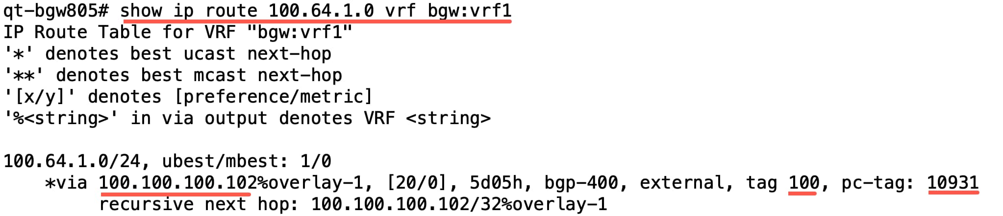
Figure 248. ACI Site 2 Spine VPNv4 route
The spine reflects the route to ACI Site 2 compute leaf switches. The next hop 10.118.112.67 is ACI Site 2 Border Gateway PTEP.
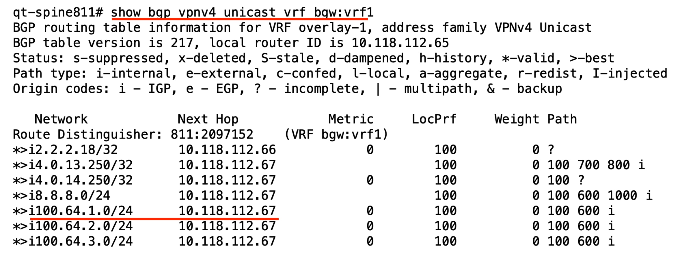
Figure 249. ACI Site 2 Compute leaf VPNv4 route
ACI Site 2 compute leaf then installs the route to its routing table.
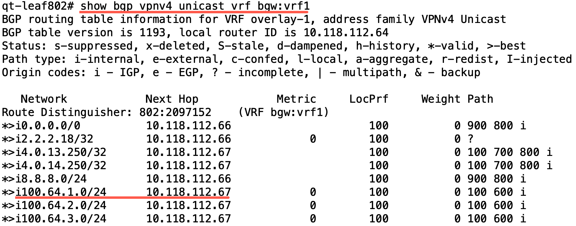
Figure 250. ACI Site 2 Compute leaf routing table
The Site 2 Border Gateway has route to 100.64.1.0/24 with proper pcTag defined in Site 2 ESG ext-1. However, once this route is reflected to the compute leaf, the leaf resets the pcTag to 1. Consequently, the leaf implicitly allows traffic to the remote external subnet without contract enforcement, as pcTag 1 is the default allowed destination.
It verifies that the external route (100.64.1.0/24) from ACI Site 1 has been successfully advertised all the way to the compute leaf switches in ACI Site 2. The external Router 1 (Site1-C8K-1) in ACI Site 1 learns the bd1 subnet (192.168.1.254/24) advertised by the ACI Site 1 border leaf.
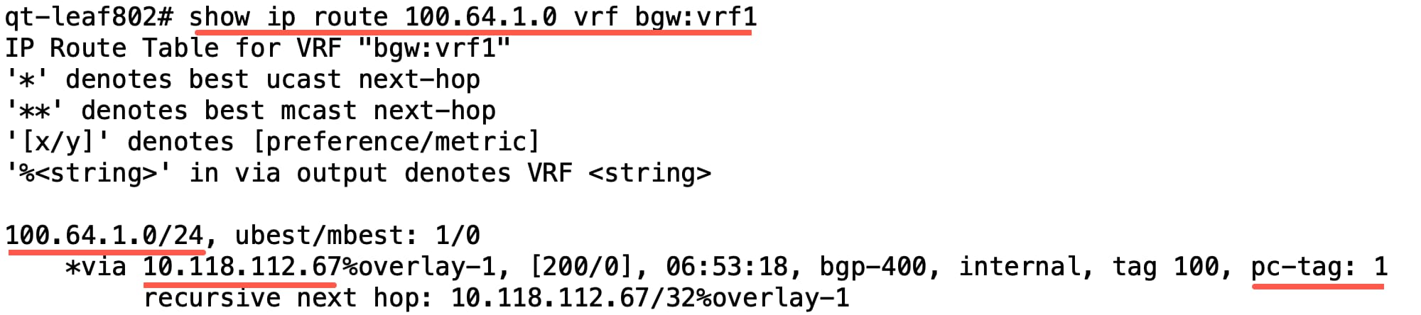
Figure 251. Site 1 external router learns ACI bd1 subnet
Data Plane Verification
The figure below illustrates a routed communication scenario between directly connected endpoint and external endpoint. Communication occurs between endpoint EP-2, a directly connected endpoint in ACI Site 2, and endpoint ExtEP-1, an external endpoint reachable through the L3Out in ACI Site 1. The Normalized VNI 50001 is defined by administrator by configuring the normalized VRF VNI when stretching VRF across two sites.
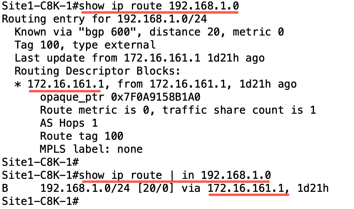
Figure 252. Data plane North-South Communication Across ACI Sites with Stretched BD
From endpoint EP-2 (192.168.1.201) pings endpoint ExtEP-1 (100.64.1.10). The packet capture of the ICMP request from EP-2 to ExtEP-1 confirms that the Layer 3 (VRF) Normalized VNI is used in the VXLAN header for inter-site data plane forwarding.
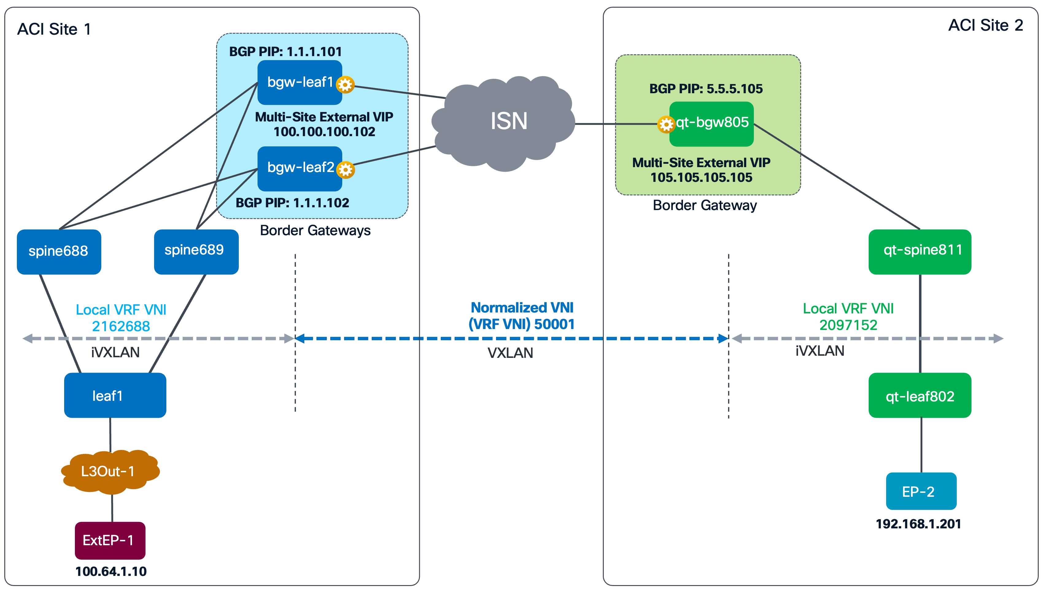
Figure 253. ICMP request from EP-2 (192.168.1.201) to ExtEP-1 (100.64.1.10)
The packet capture of the ICMP reply from ExtEP-1 to EP-2 confirms that the Layer 3 (VRF) Normalized VNI is used in the VXLAN header for inter-site data plane forwarding.
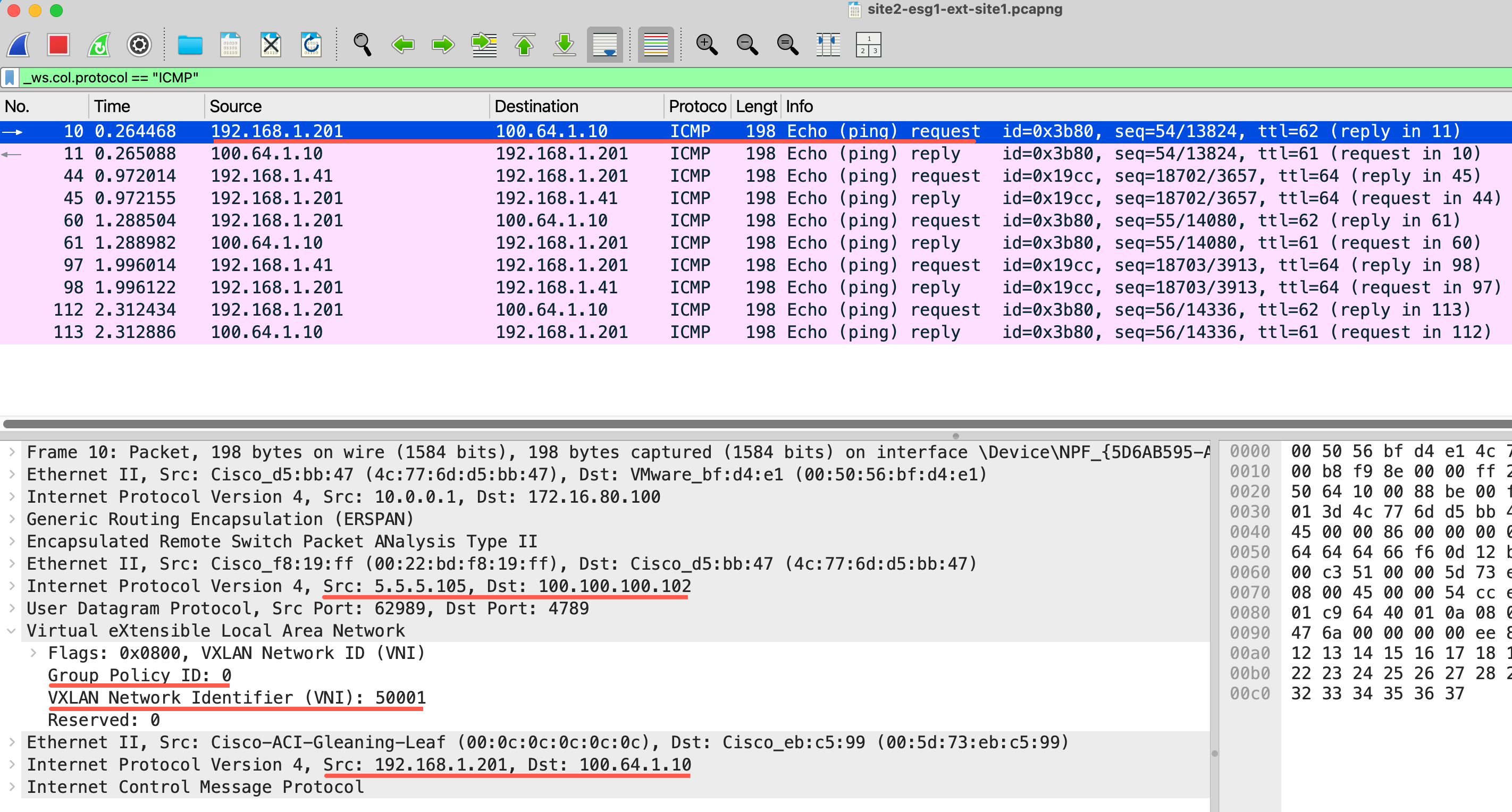
Figure 254. ICMP reply from ExtEP-1 (100.64.1.10) to EP-2 (192.168.1.201)
The figure below illustrates the policy enforcement locations for traffic an endpoint in ACI Site 2 to an external endpoint in ACI Site 1.
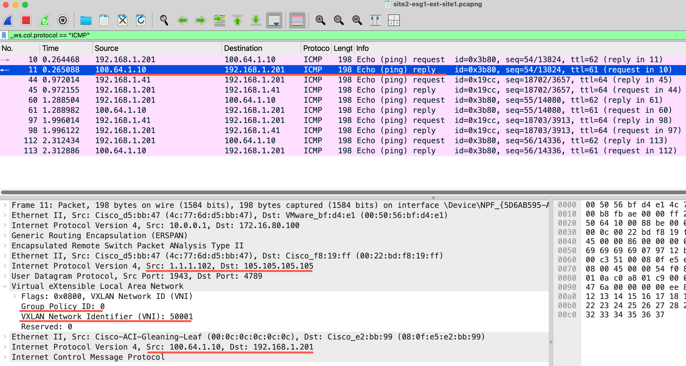
Figure 255. ACI Site 2 internal endpoint to ACI Site 1 external endpoint
Traffic from esg1 ACI Site 2 to ACI Site 1 external endpoint: the Border Gateways apply the policy in each site. At ACI Site 2, the Border Gateway maintains the pcTag information for the external subnet advertised from Site 1. However, when sending the route information to the spine switches, it uses pcTag 1 instead of the original pcTag. As a result, the compute leaf receives the route with pcTag 1. Consequently, the compute leaf does not apply the policy for the traffic destined to the external subnet. Instead, the Border Gateway enforces the policy in ACI Site 2. Upon traffic reaching Site 1, Site 1 Border Gateway can derive the source class of the source endpoint using the BGP EVPN control plane and the destination class based on the external subnet because of the external subnet selector. As a result, the Border Gateway enforces the policy and forwards the traffic to the border leaf.
The figure below illustrates the policy enforcement locations for the return traffic.
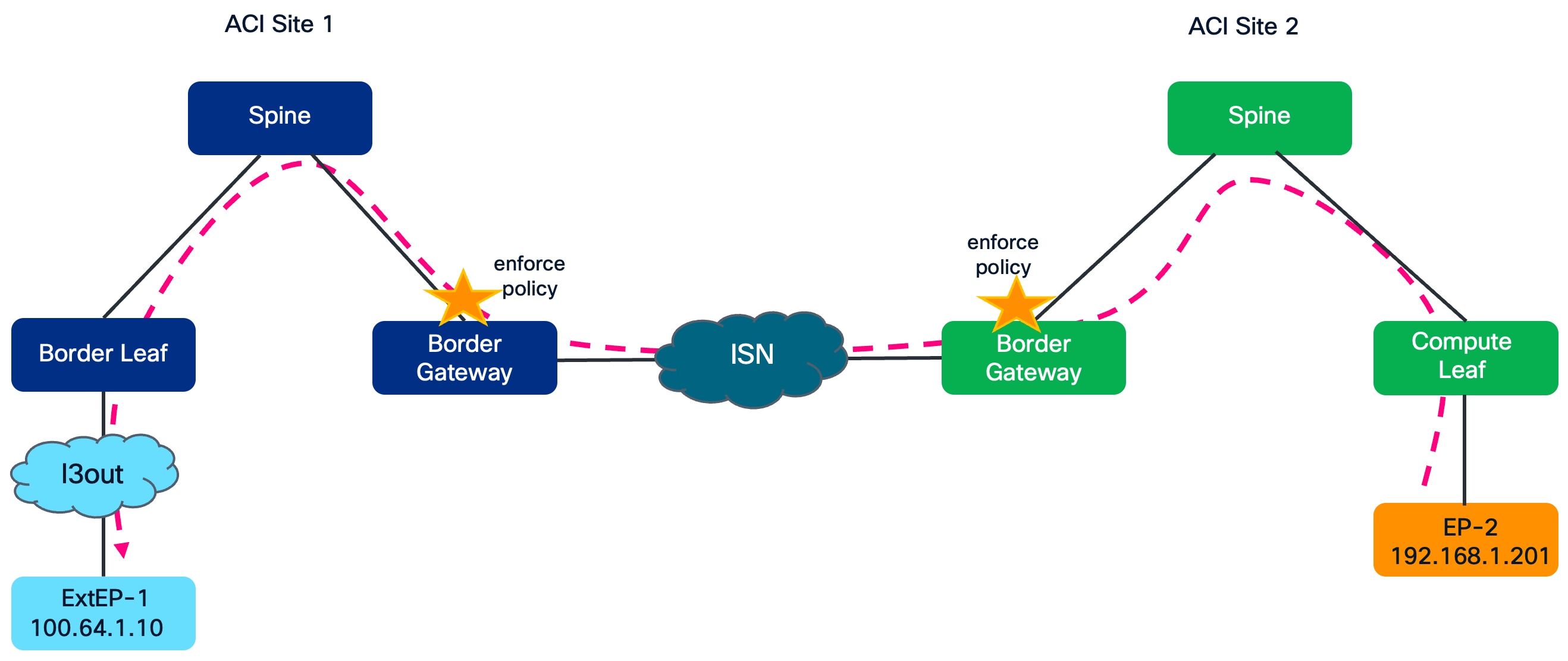
Figure 256. ACI Site 1 external endpoint to ACI Site 2 internal endpoint
Traffic from an external endpoint through ACI Site 1 to an endpoint in ACI Site 1: At ACI Site 1, the Border Gateway enforces the security policy for traffic from an external endpoint to an endpoint in ACI Site 2 because the border leaf in Site 1 cannot derive destination class based on the destination IP address. It is because the Border Gateways in ACI Site 1 sets the Do-Not-Learn bit on traffic received from Site 2, which prevents the border leaf from learning the remote endpoint. As a result, policy enforcement at Site 1 is performed by the Border Gateway. When the traffic reaches ACI Site 2, the Border Gateway does not apply the policy. Although the Border Gateway in ACI Site 2 has the destination endpoint information advertised by local spine switches, it does not program the information to the hardware table for scalability reason. As a result, the compute leaf attached to the destination endpoint enforces the policy.
Use Case 6: North-South Communication Across ACI Sites with Non-stretched BD
This use case describes communication between an endpoint and an external endpoint in different ACI sites, like the Use Case 5: North-South Communication Across ACI Sites with Stretched BD, but the BD is deployed locally, not stretched. The figure below illustrates the logical design; an endpoint in a locally defined BD in ACI Site 1 talks to an external endpoint behind the L3Out of ACI Site 2, and vice versa.
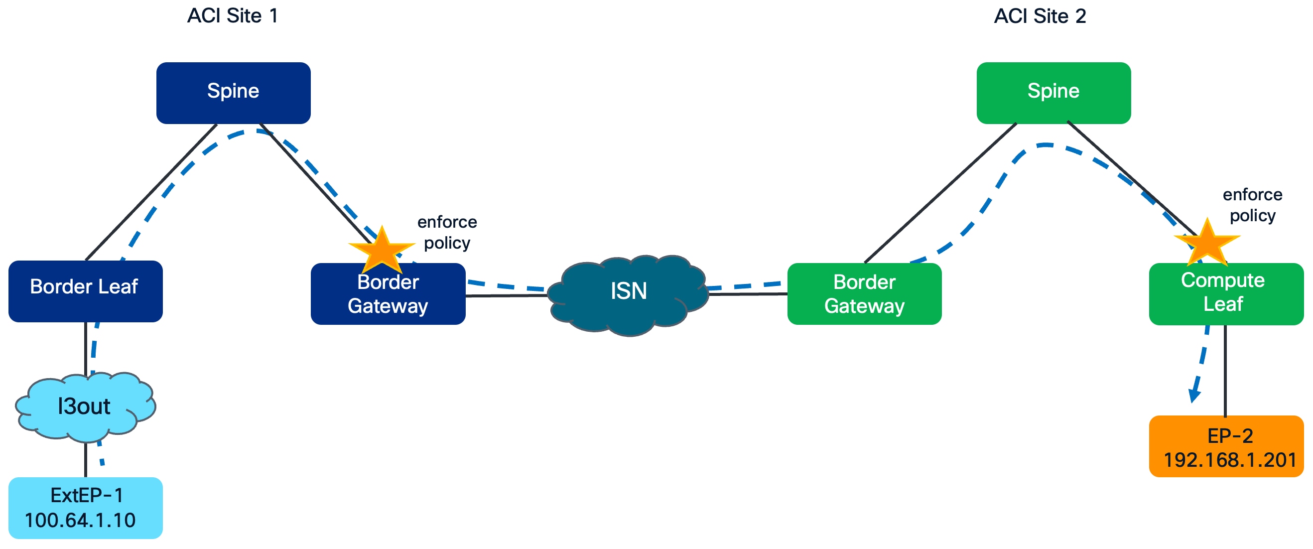
Figure 257. North-South Communication across ACI sites with non-stretched (local) BD
Because BD bd50 is local to ACI Site 1, advertising its subnets to the external router connected to ACI Site 2 requires creating a route-map in ACI Site 2. This route-map facilitates advertising the bd50 subnet (192.168.50.0/24 in this example) to the external network (L3Out-2). Most of the configuration elements including ESG ext-1, L3Out-2, bd50, and esg50 are assumed to be configured as per previous use cases.
The main configuration steps are as follows:
On ACI Site 1:
● Advertise the bd50 subnet (192.168.50.0/24) to the external router connected to ACI Site 2.
● Add 100.68.1.0/24 as an external subnet selector to ESG ext-1.
● Create and apply a contract between esg50 and ext-1 to permit communication from the bd50 subnet to 100.68.1.0/24.
On ACI Site 2:
● Create a default-export route map to permit 100.68.1.0/24
● Create and apply a contract between esg50 and ext-1 to allow communication from the bd50 subnet to subnet 100.68.1.0/24.
The figures below show the configuration examples in ACI Site 1. Add 100.68.1.0/24 as to External Subnet Selector ESG ext-1.
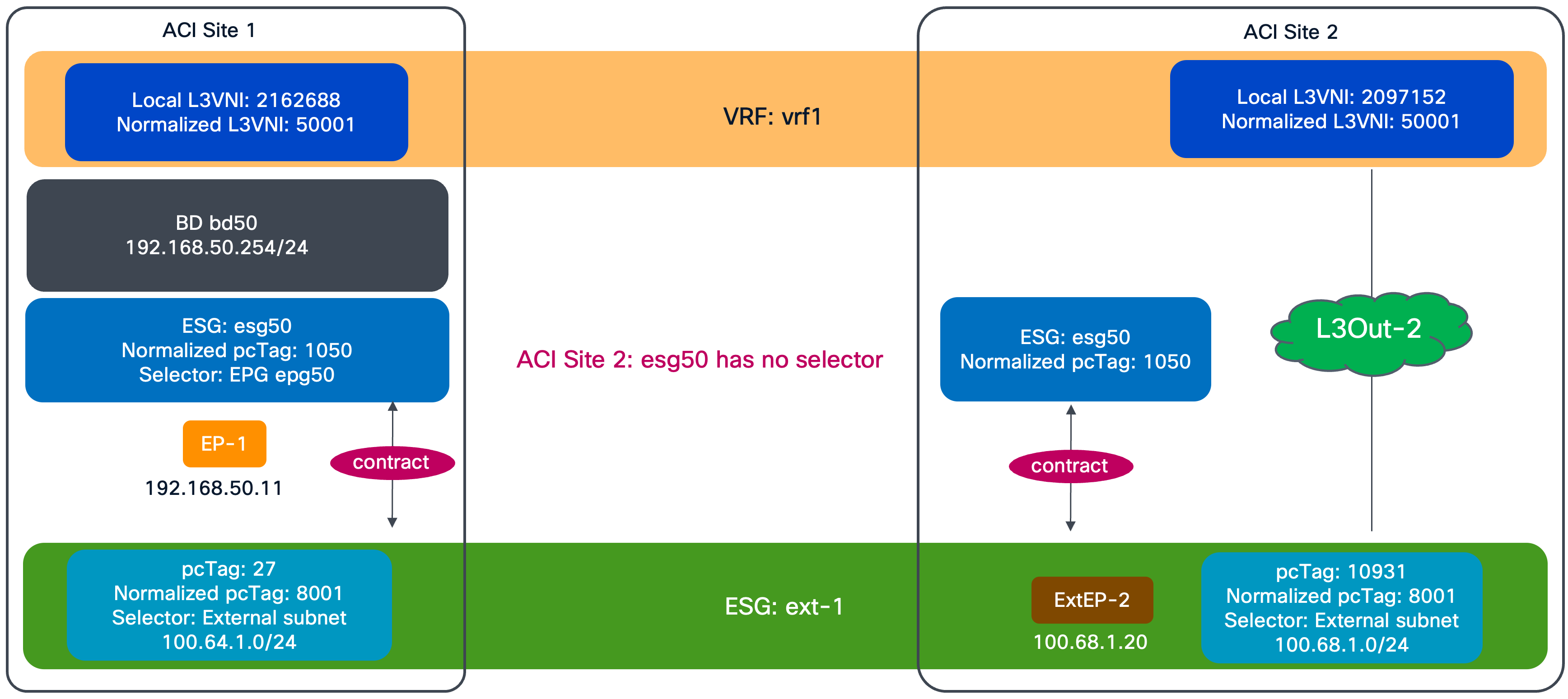
Figure 258. Add 100.68.1.0/24 to external subnet selectors of ESG ext-1
Create a contract “esg50-to-ext-1”, and configure a filter as needed; in this example, the contract has a filter to allow all IP traffic.
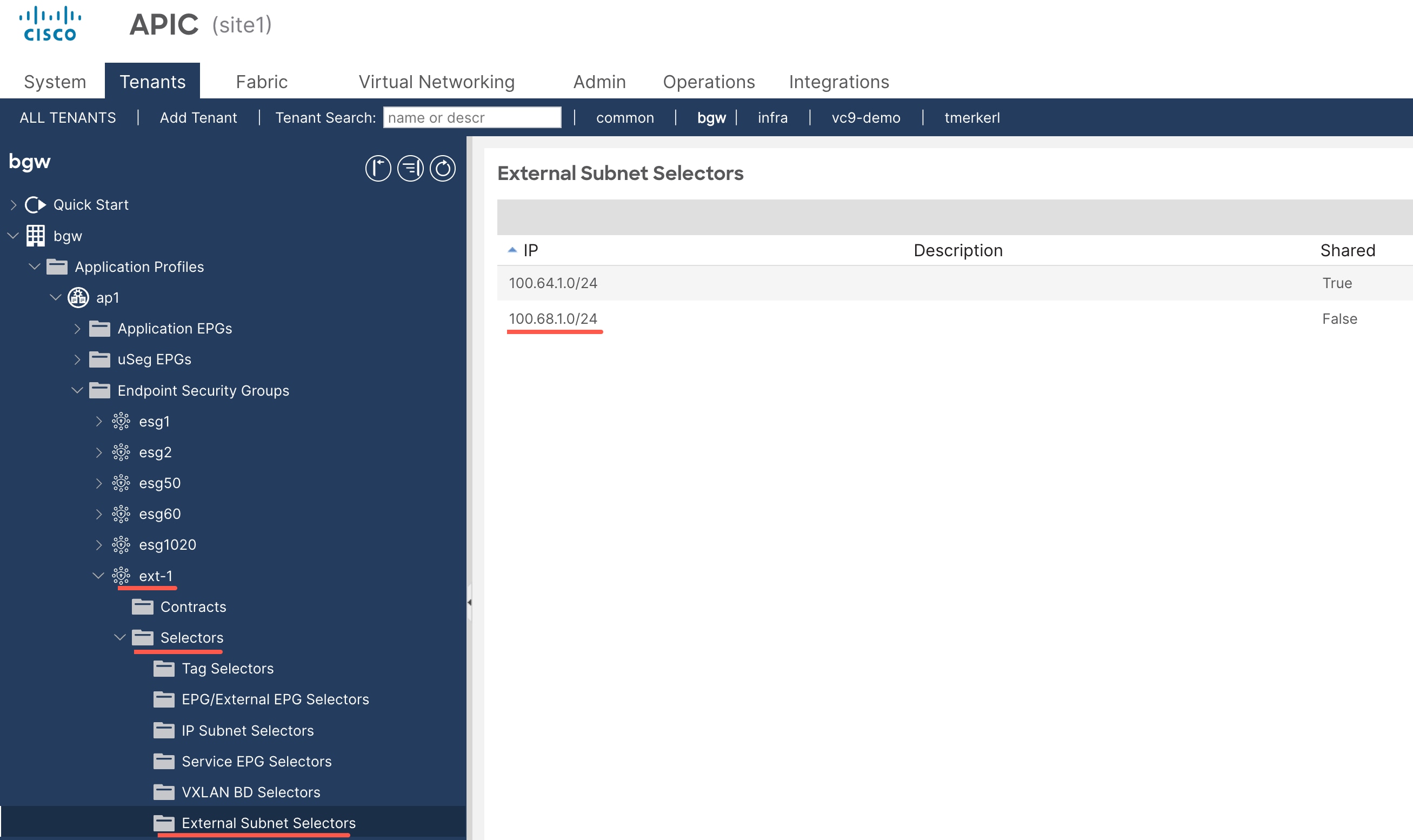
Figure 259. ACI Site 1 contract esg50-to-ext-1
Apply this contract between esg1 and ext-1, ensuring that one side is set as the consumer and the other as the provider.

Figure 260. ACI Site 1 esg50 contract consumer
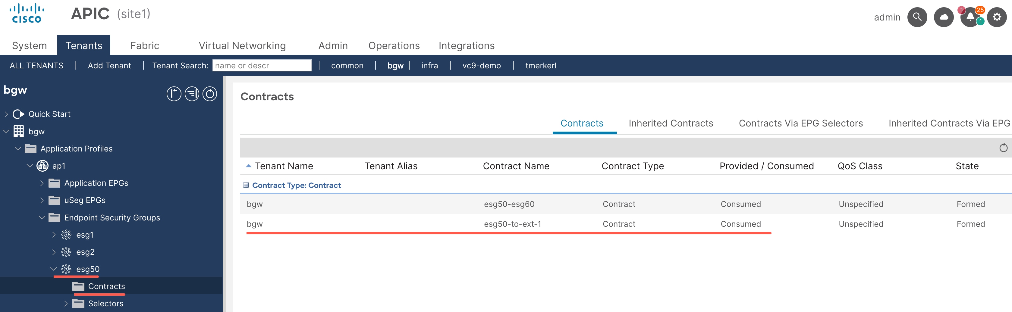
Figure 261. ACI Site 1 ESG ext-1 contract provider
The figures below show the configuration examples in ACI Site 2. On ACI Site 2, in the L3Out object (c8k-1-bgp in this example), right click on Route-map for Import and export route control, choose “Create default-export route-map”.
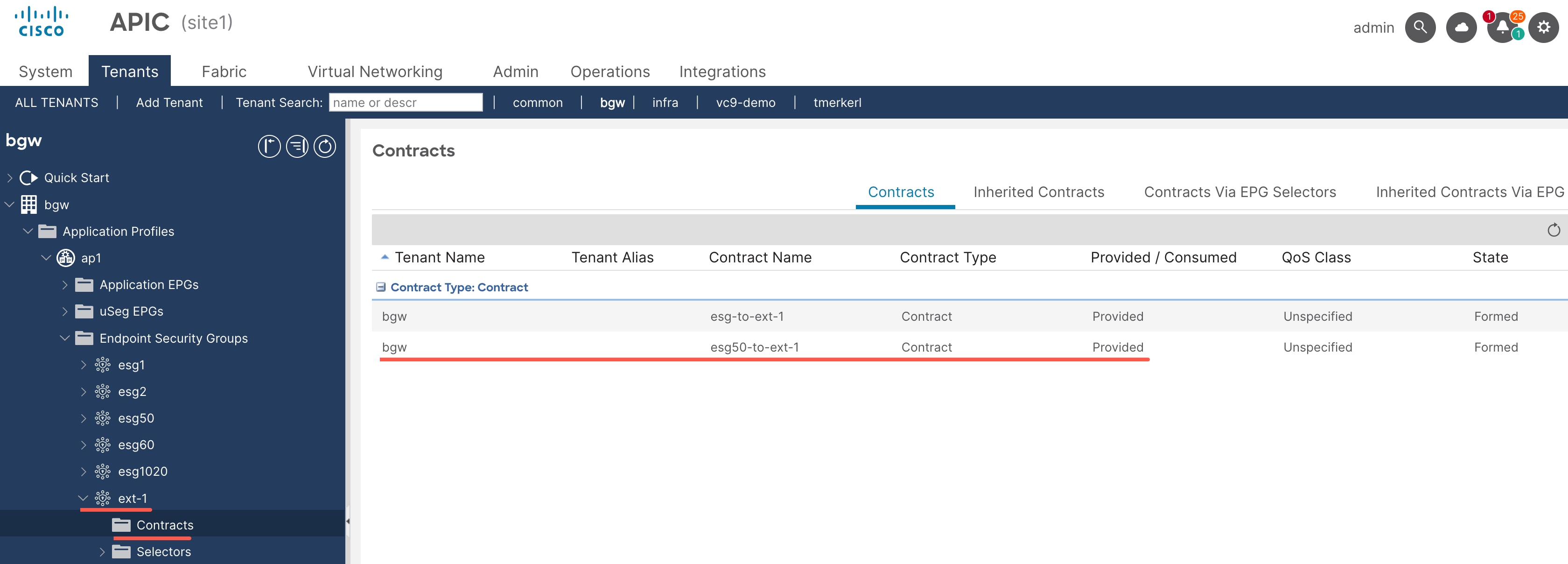
Figure 262. ACI Site 2 create default-export route-map
From the drop-down list, choose default-export then click “+” to add the context entry.
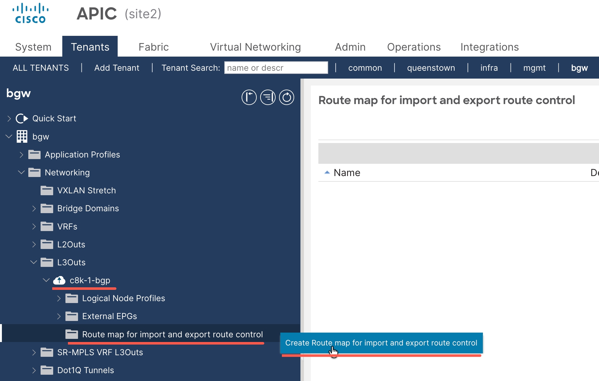
Figure 263. Choose default-export contract and add context entry
Give a descriptive context name, fill in description text box if needed, and then click “+”.
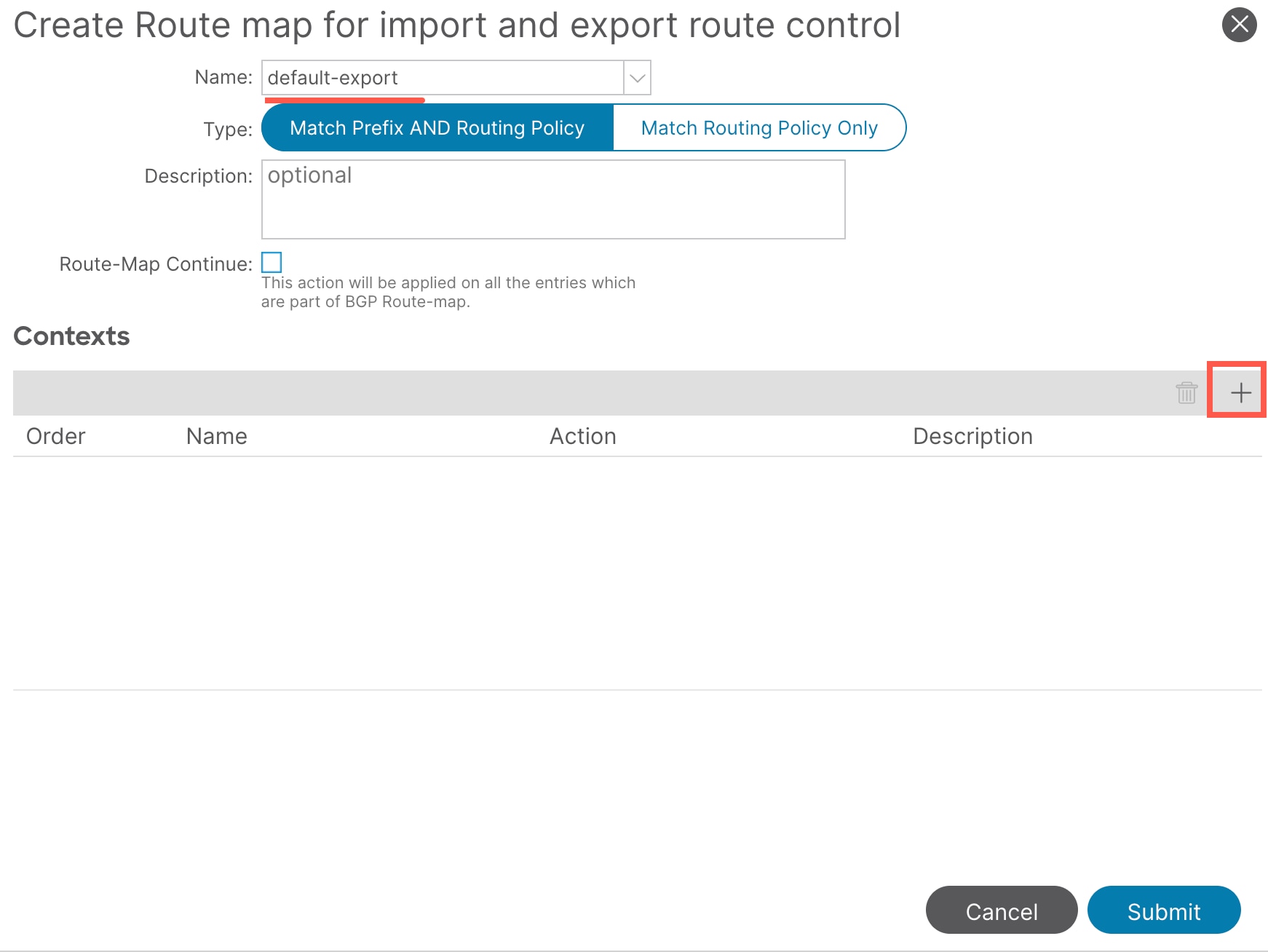
Figure 264. Create context
From the Rule Name drop-down list, click Create match Rule for a Route-map, this step is used to create a match rule to match prefix 192.168.50.0/24.
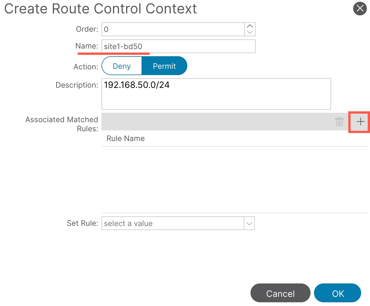
Figure 265. Create a match rule
Give match rule a descriptive Name for example site1-bd50-subnet, then click “+” in the Match Prefix working area.
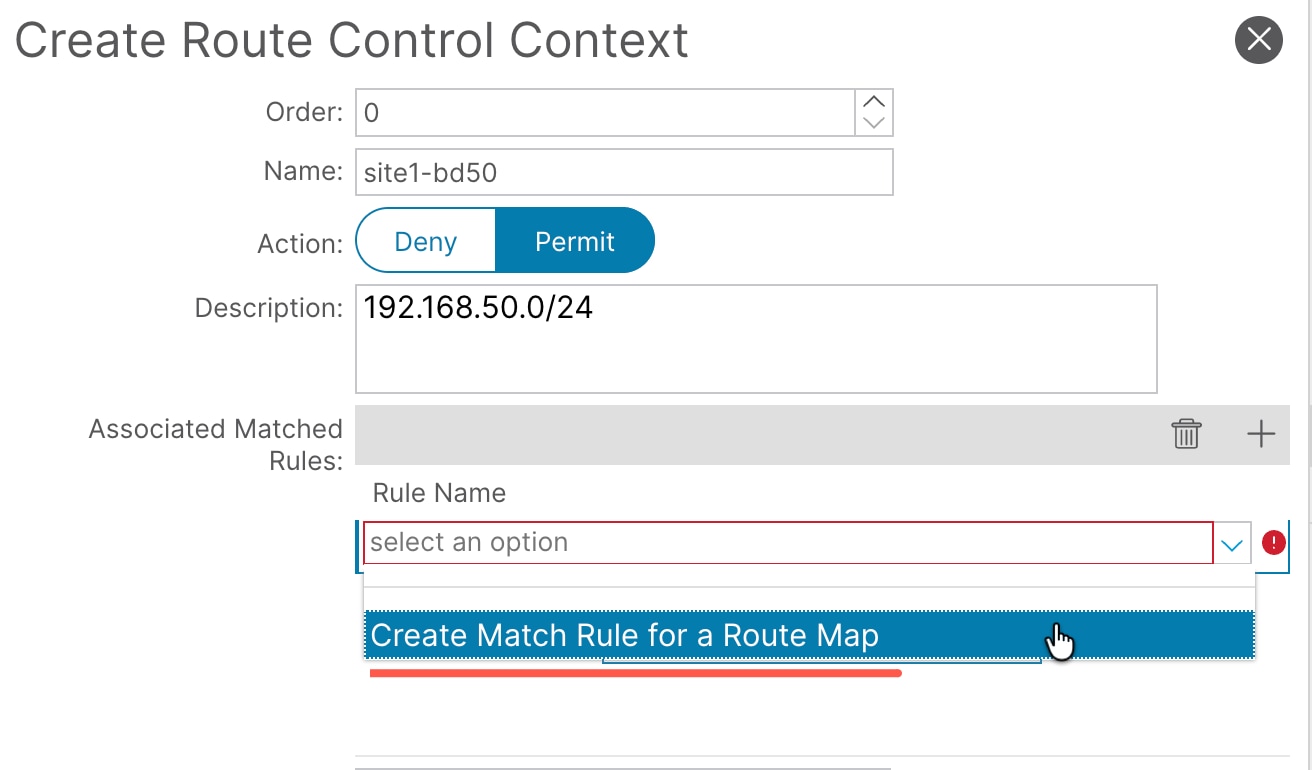
Figure 266. Create match prefix
In the IP field, type 192.168.50.0/24 then click OK.
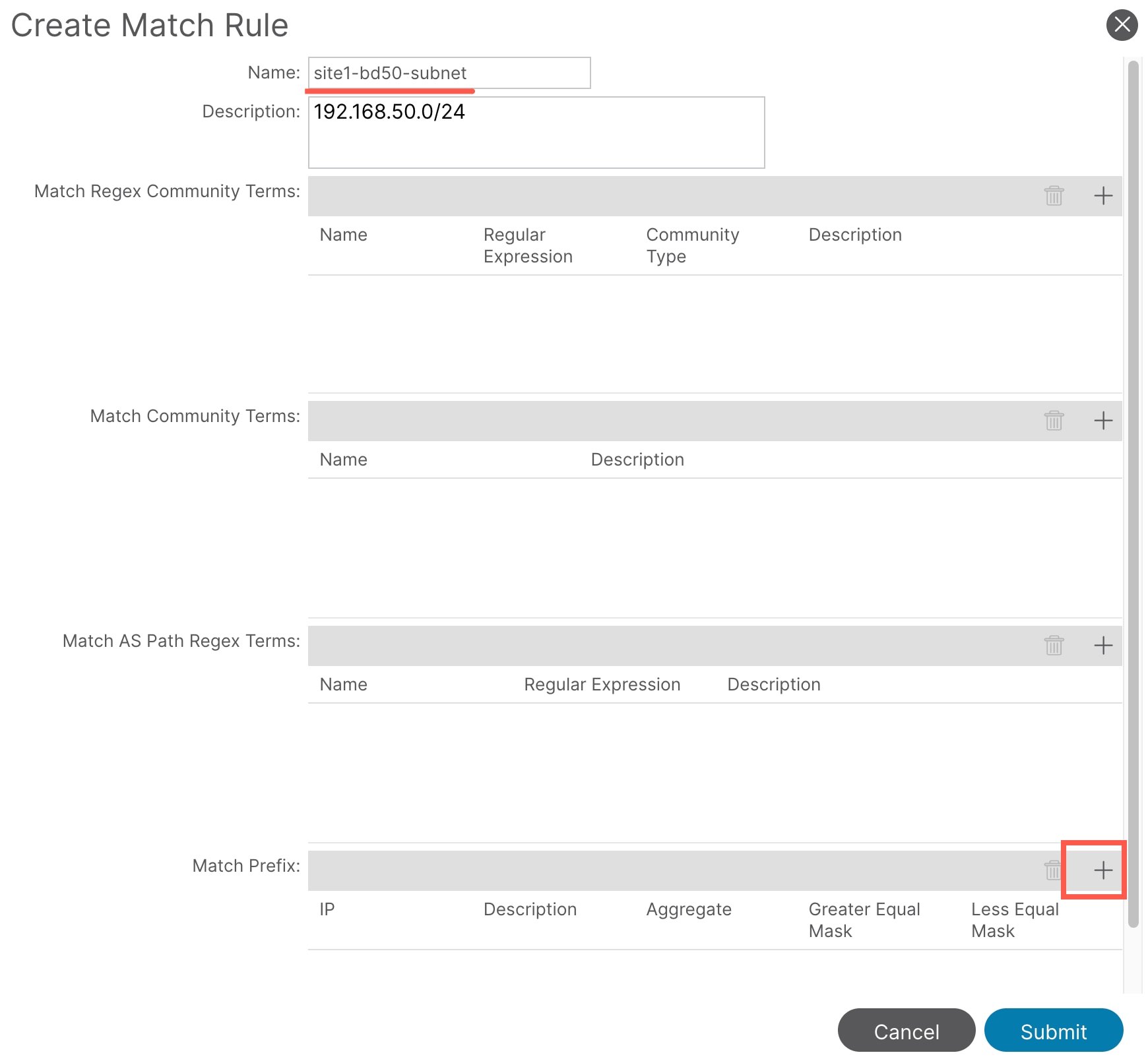
Figure 267. Type 192.168.50.0/24 for IP field
Then, click Submit to create the match rule.
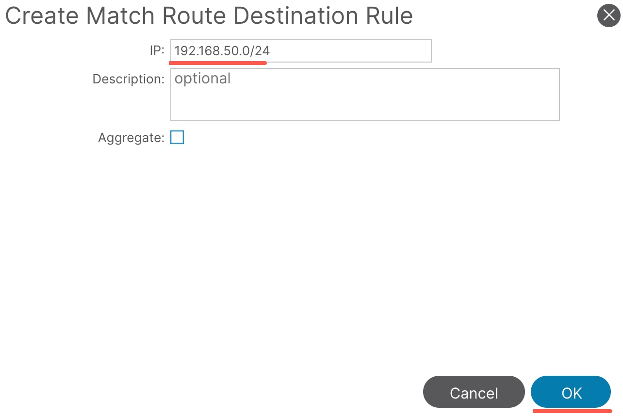
Figure 268. Submit to finish creating a match rule
Click Update to associate the match rule to the route control context.
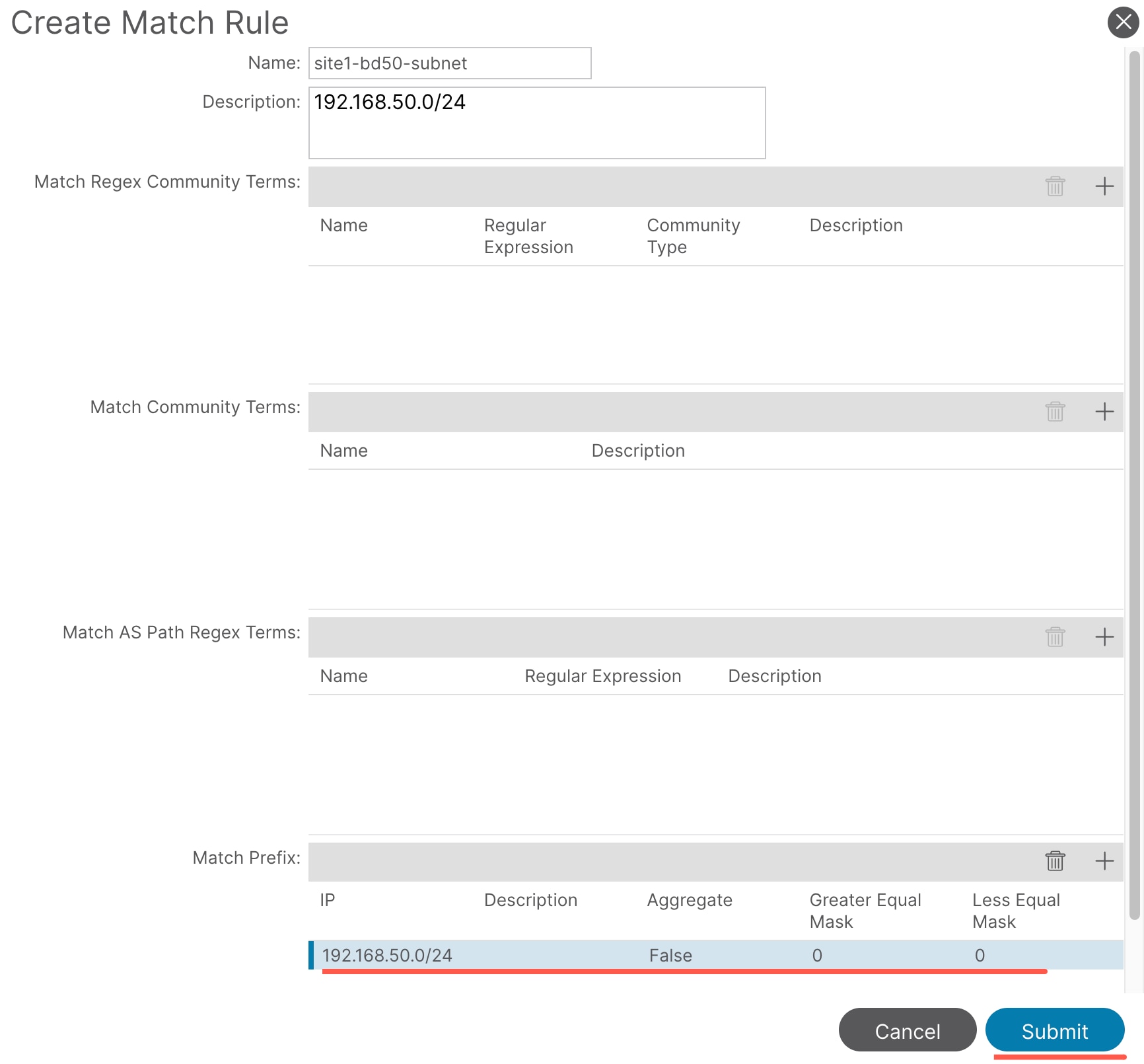
Figure 269. Update the rule
Then click OK to add the route control context entry to default-export route-map.
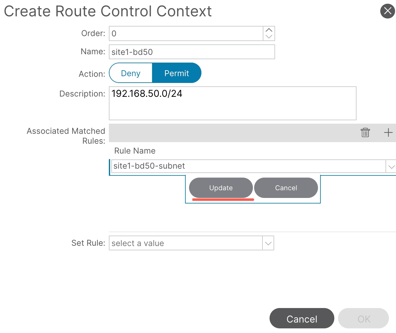
Figure 270. Click OK
Click Submit to complete default-export route-map creation.
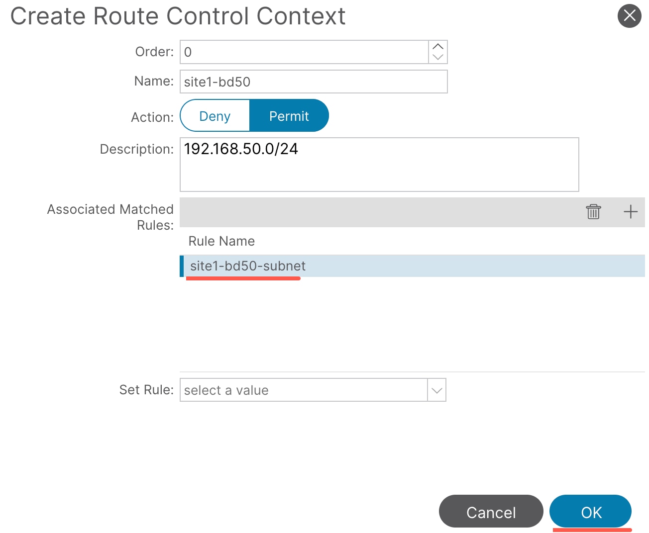
Figure 271. Submit to finish default-export route-map creation
Confirm default-export route-map is created.
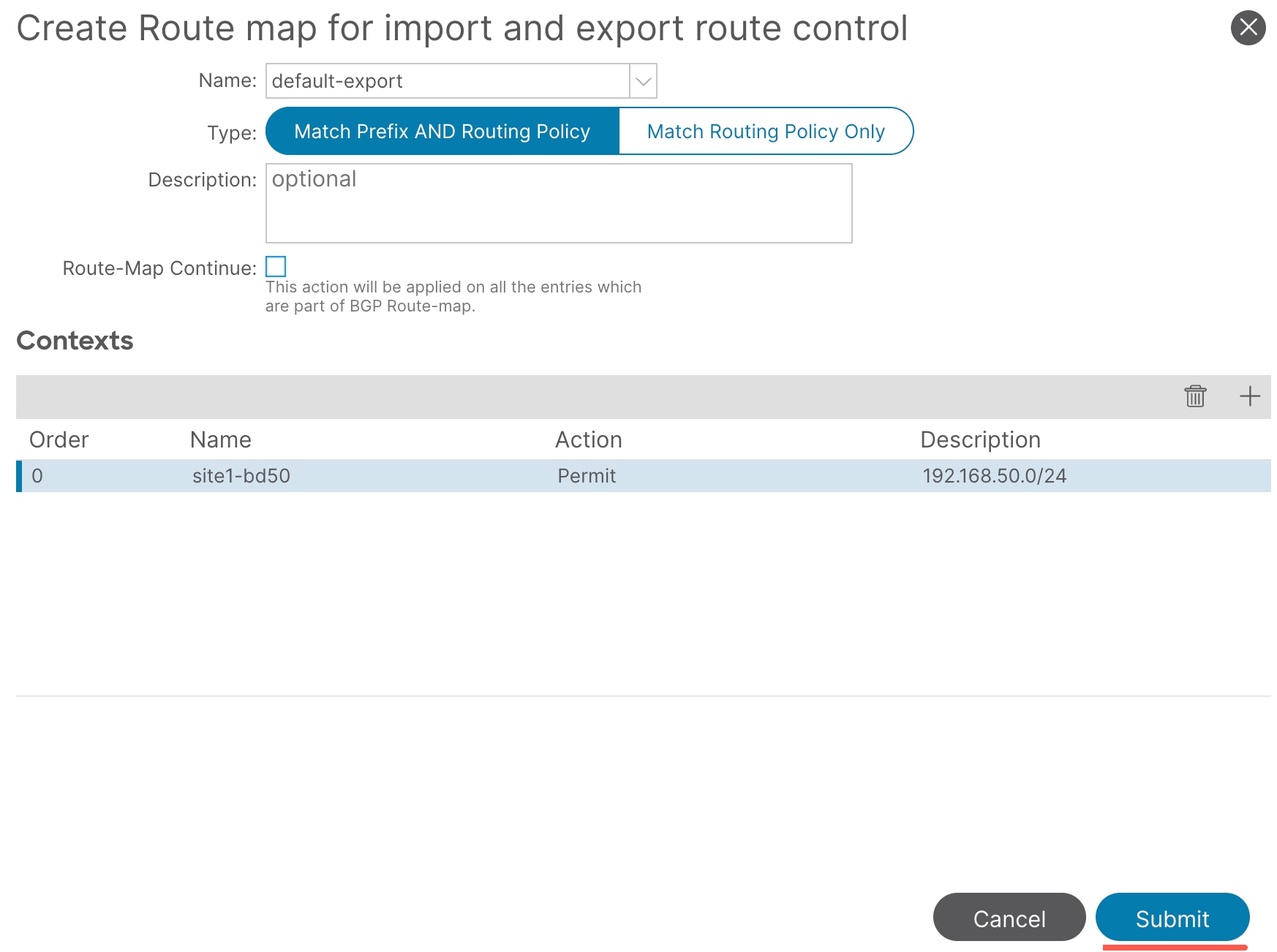
Figure 272. Default-export route-map completion
Create contract “esg50-to-ext-1” and configure a filter as needed; in this example, the contract has a filter to allow all IP traffic.
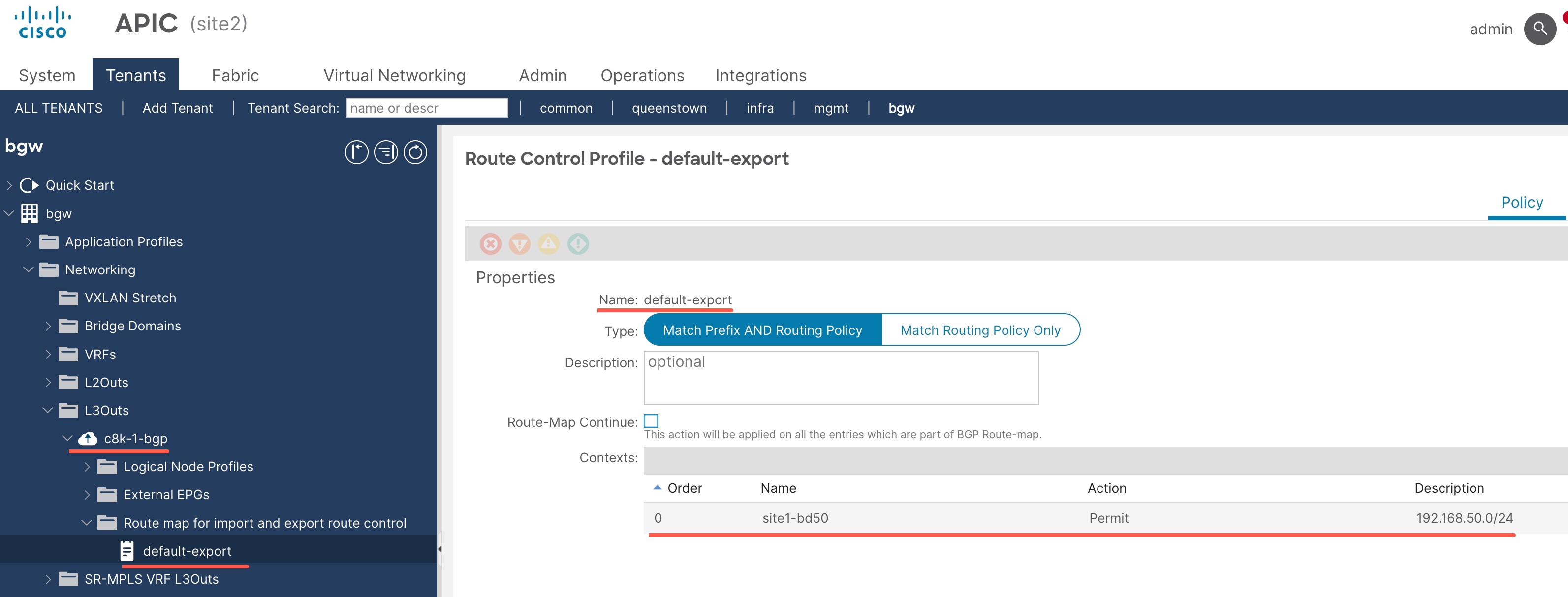
Figure 273. ACI Site 2 contract esg50-to-ext-1
Apply this contract between esg1 and ext-1, ensuring that one side is set as the consumer and the other as the provider.
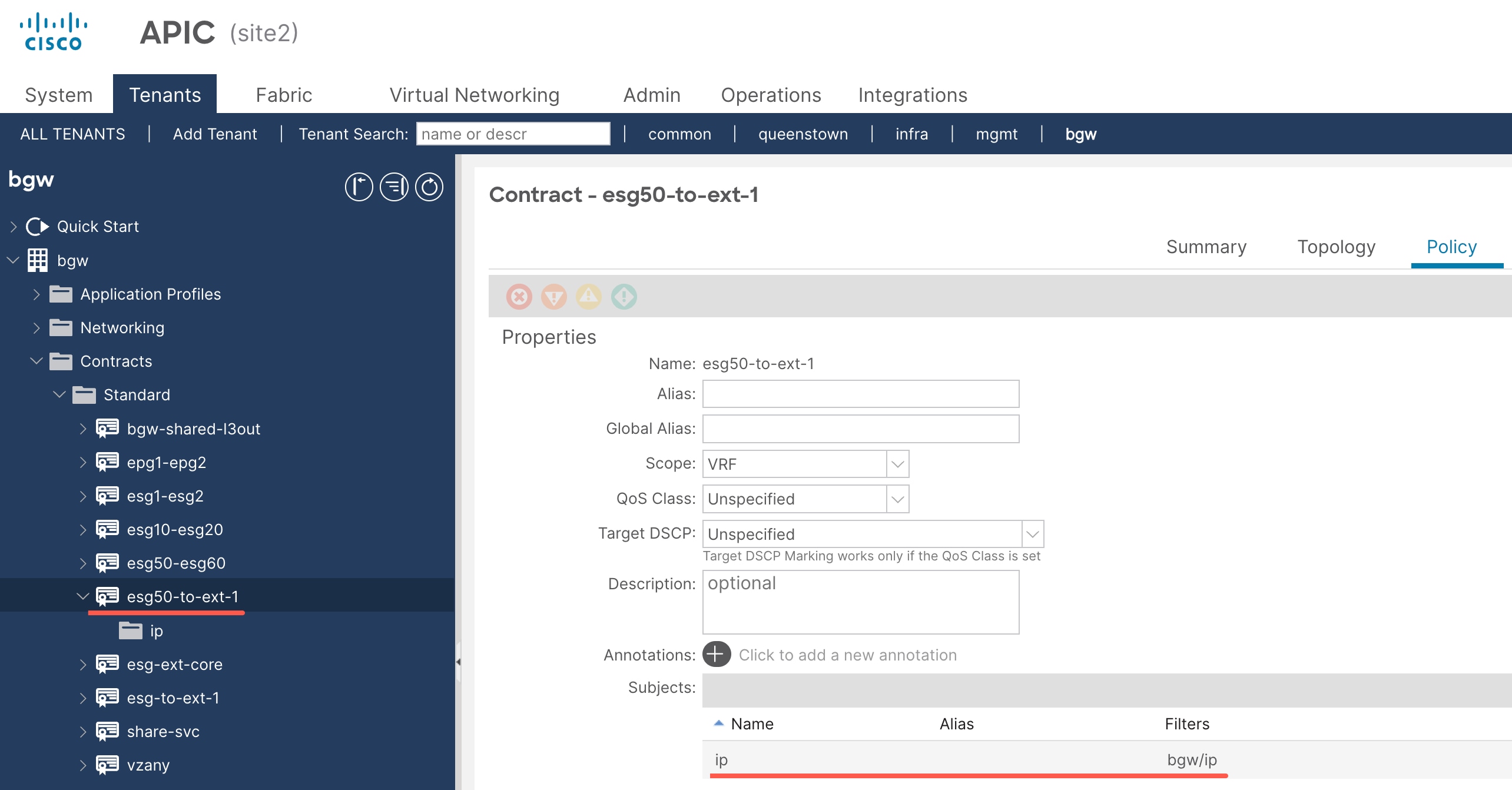
Figure 274. ACI Site 2 ESG esg50 contract consumer
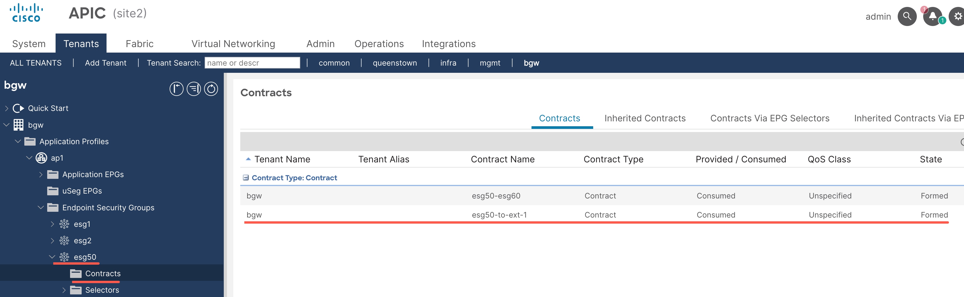
Figure 275. ACI Site 2 ESG ext-1 contract provider
Control Plane Verification
The following diagram illustrates the topology used in this verification.
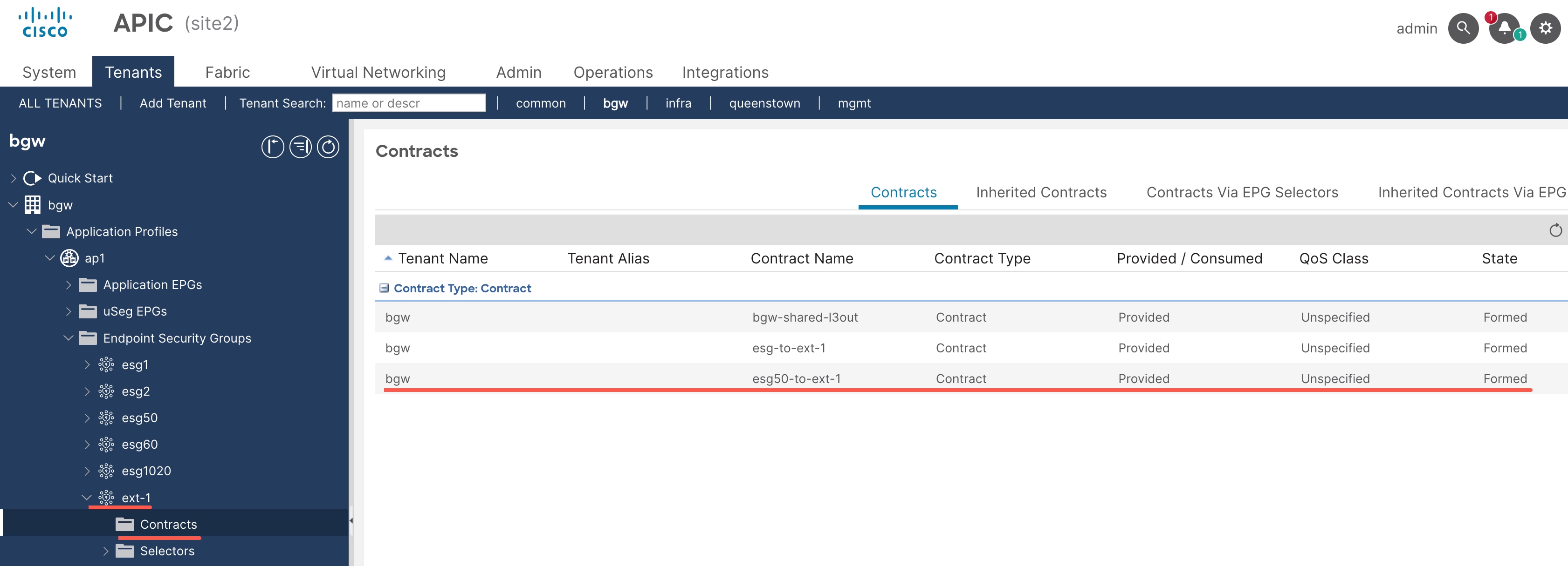
Figure 276. North-South Communication Across Sites with non-stretched (local) BD
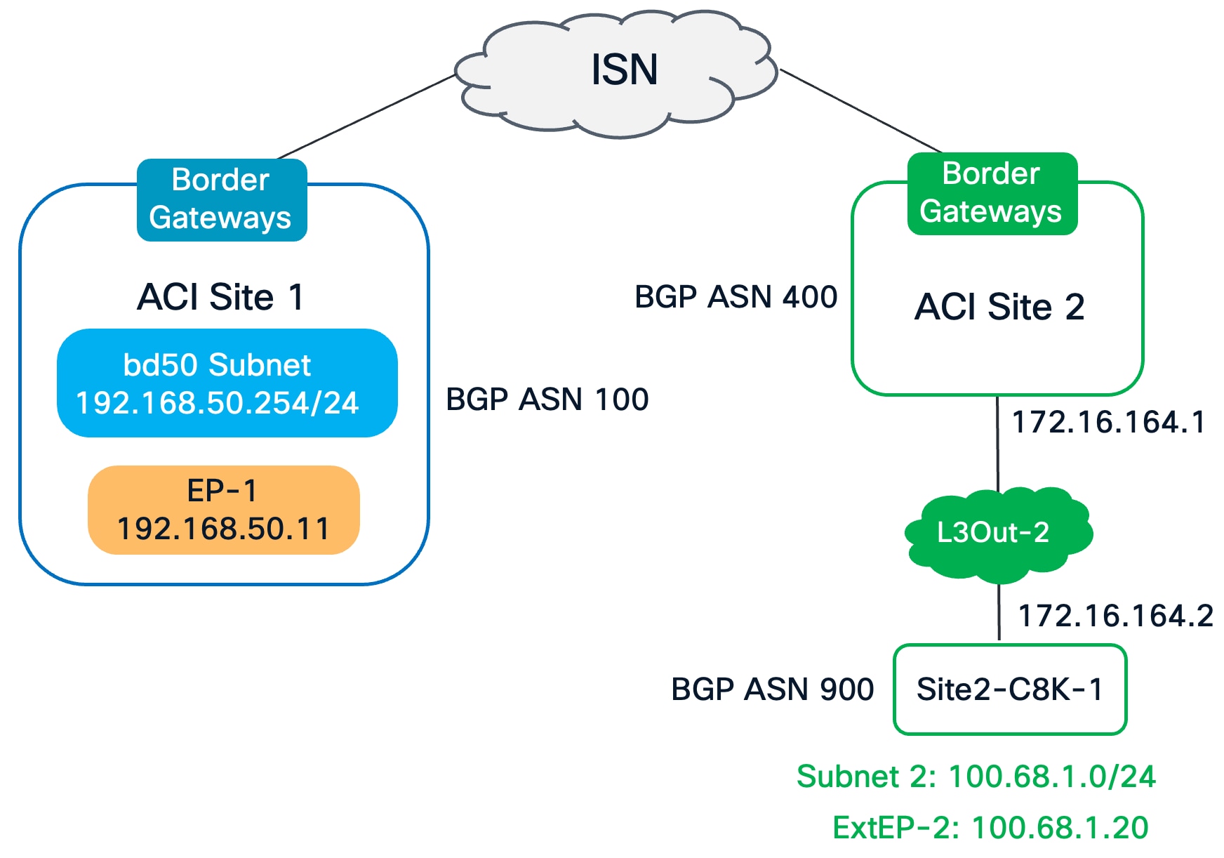
Figure 277. ESG esg50 and ESG ext-1 pcTag
Verify that the external router Site2-C8K-1 in ACI Site 2 has successfully received and installed the route to subnet 192.168.50.0/24, which originates from ACI Site 1, in its routing table.
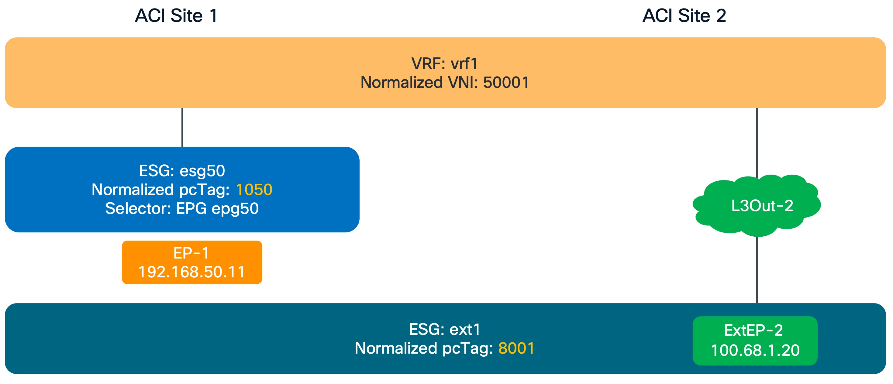
Figure 278. ACI Site 2 External router learns ACI Site 1 non-stretched (local) BD Subnet
For reference, and in line with the previous use case, the compute leaf switches in ACI Site 1 learns the external subnet 100.68.1.0/24 located in ACI Site 2 via the ACI Site 1 Border Gateways. 10.1.248.2 and 10.1.248.7 are the PTEP addresses of Border Gateway 1 and Border Gateway 2 in ACI Site 2, respectively.
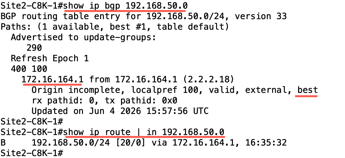
Figure 279. ACI Site 1 Compute leaf learns ACI Site 2 external subnet
Data Plane Verification
The figure below illustrates a routed communication scenario between directly connected endpoint and external endpoint. Communication occurs between endpoint EP-1, a directly connected endpoint in ACI Site 1, and endpoint ExtEP-2, an external endpoint reachable through the L3Out in ACI Site 2. The Normalized VNI 50001 is defined by administrator by configuring the normalized VRF VNI when stretching VRF across two sites
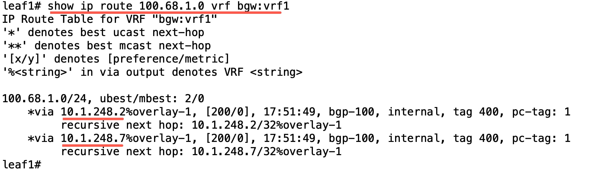
Figure 280. Data plane North-South Communication Across ACI Sites with Non-stretched BD
Ping from an endpoint (192.168.50.11) in ACI Site 1 to an external endpoint (100.68.1.20) in ACI Site 2. The packet capture of the ICMP request from EP-1 to ExtEP-2 confirms that the Layer 3 (VRF) Normalized VNI is used in the VXLAN header for inter-site data plane forwarding.
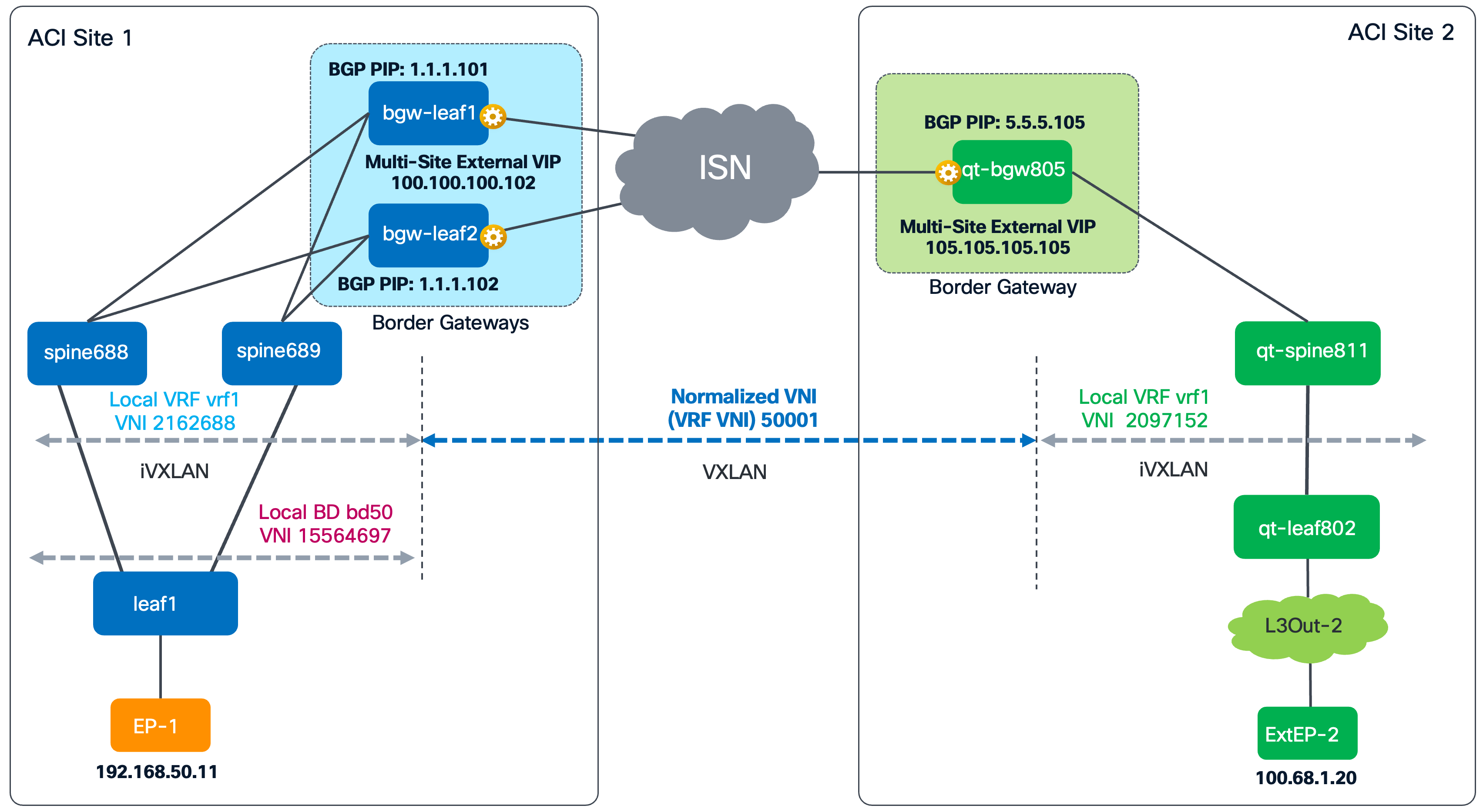
Figure 281. ICMP request from EP-1 (192.168.50.11) to ExtEP-2 (100.68.1.20)
The packet capture of the ICMP reply from ExtEP-2 to EP-1 confirms that the Layer 3 (VRF) Normalized VNI is used in the VXLAN header for inter-site data plane forwarding.
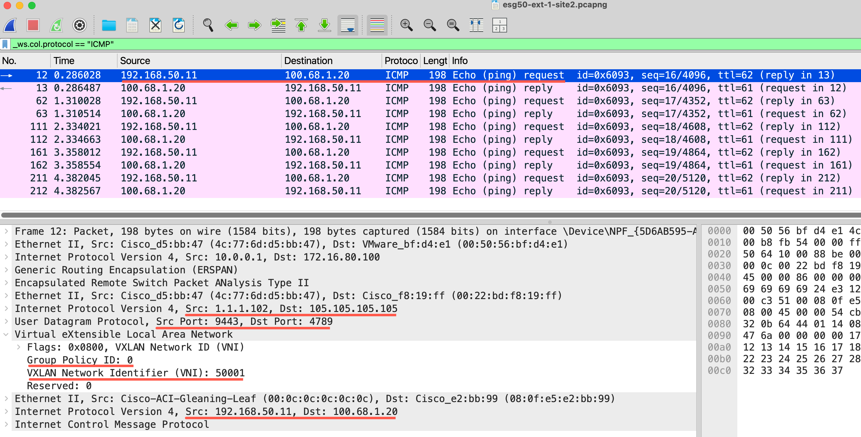
Figure 282. ICMP reply from ExtEP-2 (100.68.1.20) to EP-1 (192.168.50.11)
The figure below illustrates the policy enforcement locations for traffic an endpoint in ACI Site 1 to an external endpoint in ACI Site 2.
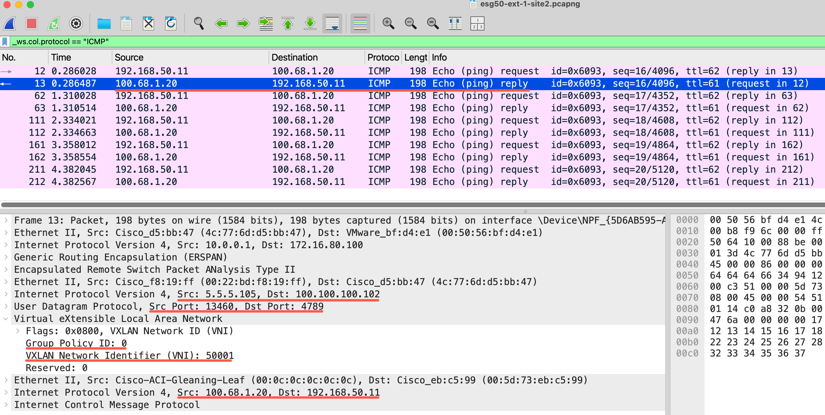
Figure 283. ACI Site 1 internal endpoint to ACI Site 2 external endpoint
Traffic from an endpoint in ACI Site 1 to an external endpoint through ACI Site 2: The Border Gateway applies policy in each site. Site 1 Border Gateway learns remote external subnet from Site 2 with pcTag advertised by Site 2 Border Gateway, which uses pcTag of 1 when it is advertised within ACI Site 1. It results that ACI Site 1 compute leaf does not apply the policy for the traffic destined to the remote external subnet and ACI Site 1 Border Gateway applies the policy instead. Upon traffic reaching ACI Site 2, ACI Site 2 Border Gateway applies policy because both source and destination class IDs can be derived.
The figure below illustrates the policy enforcement locations for the return traffic.
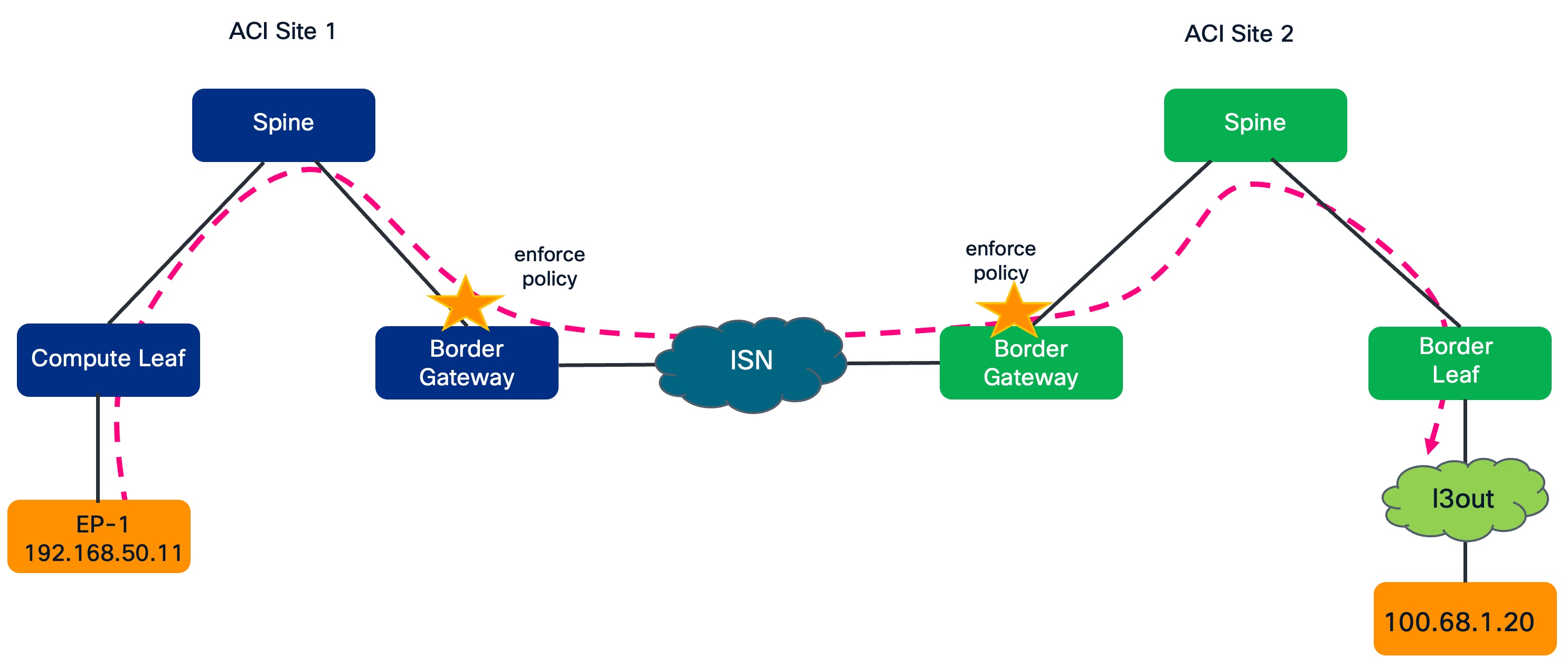
Figure 284. ACI Site 2 external endpoint to ACI Site 1 internal endpoint
Traffic an external endpoint through ACI Site 2 to an endpoint in ACI Site 1: the Border Gateway applies the policy for traffic from an external endpoint to an endpoint in ACI Site 1 because Site 2 border leaf in ACI Site 2 cannot derive destination class based on the destination IP address. It is because the Border Gateways in ACI Site 2 sets the Do-Not-Learn bit on traffic received from Site 1, which prevents the border leaf from learning the remote endpoint. As a result, policy enforcement at Site 2 is performed by the Border Gateway. When the traffic reaches ACI Site 1, the compute leaf applies the policy because the Border Gateways do not learn local endpoints in the same sit, which means Border Gateways will implicitly permit the traffic.
Use Case 7: Transit Routing Across ACI Sites
In this use case, the two ACI Sites play a transit function to forward traffic between L3Outs across ACI Sites. The figure below illustrates the logical diagram. An external endpoint via L3Out-1 in ACI Site 1 communicate with an external endpoint via L3Out-2 in ACI Site 2.
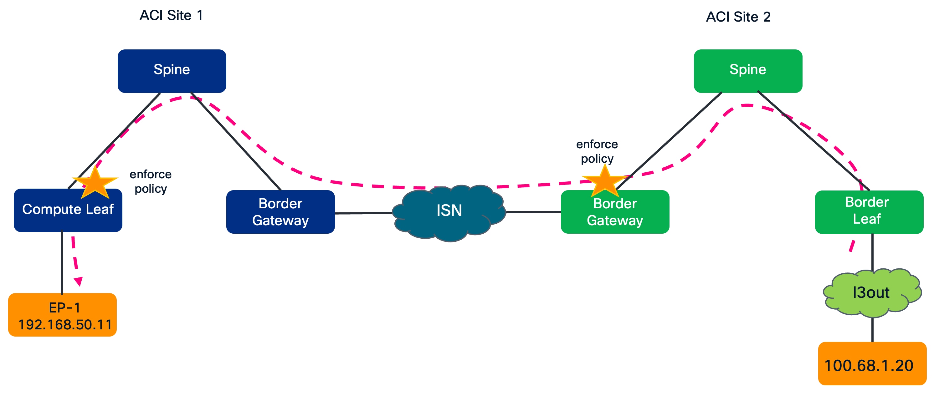
Figure 285. Transit routing across ACI Sites
The figure below illustrates the topology and IP addresses used in this section.
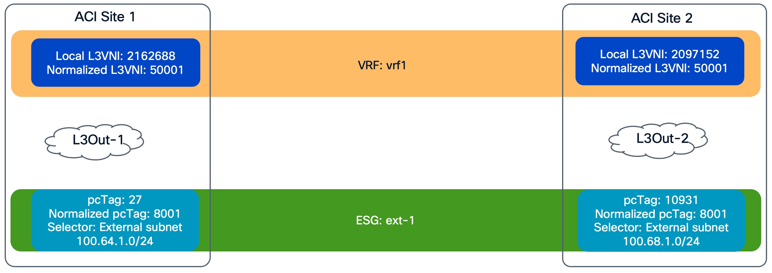
Figure 286. Transit routing across ACI Sites networking view
To enable communication between the two external endpoints (100.64.1.10 and 100.68.1.20), both external routes must be exchanged between ACI Sites; 100.64.1.0/24 from ACI Site 1 must be advertised to Router 2, and the route 100.68.1.0/24 from ACI Site 2 must be advertised to Router 1.
Transit routing configuration has been documented in detail at https://www.cisco.com/c/en/us/td/docs/dcn/aci/apic/6x/l3-configuration/cisco-apic-layer-3-networking-configuration-guide-62x/transit-routing-layer3-config-62x.html
Configure a route-map for advertising external route from ACI Site 2 to ACI Site 1. On ACI Site 1 L3Out, right click on L3Out object and choose “Create Route map for import and export route control”.
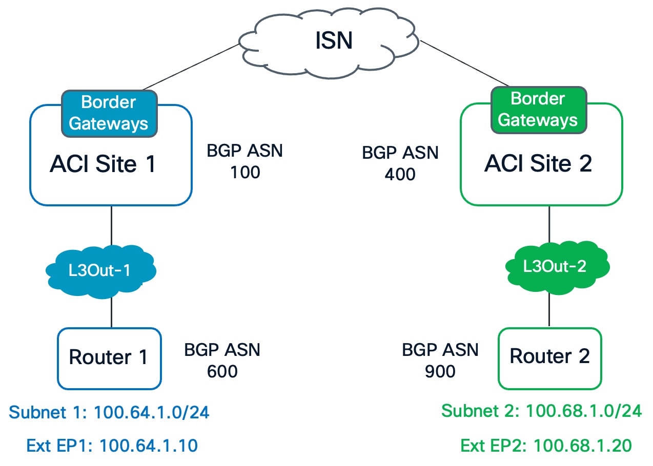
Figure 287. ACI Site 1 Create route map for import and export route control
Name the route map for example “transit-100-68”, keep Type as default “Match Prefix AND Routing Policy”, click “+” to add a Context.
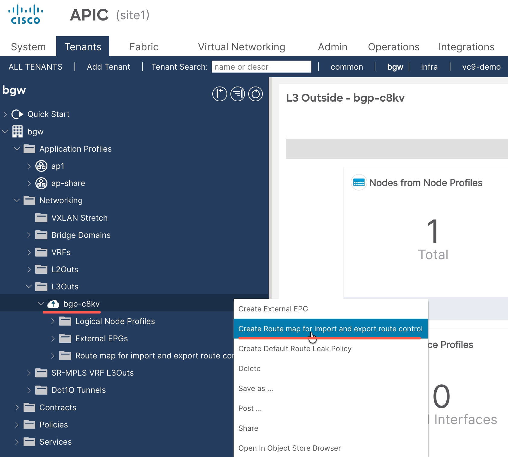
Figure 288. ACI Site 1 Route-map
Name the context, for example 100-68, then click “+” to add a match rule which is to match the prefix 100.68.1.0/24 that is the external prefix from ACI Site 2.
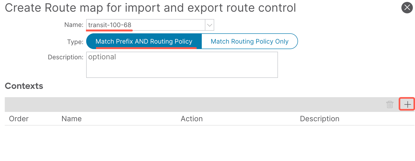
Figure 289. ACI Site 1 Route-map route control context
Click the drop-down list and scroll all the way to the bottom then choose “Create Match Rule for a Route Map”
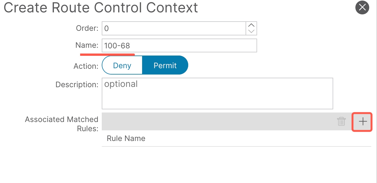
Figure 290. ACI Site 1 Create a match rule
Name the match rule for example “100-68-1”, then click “+” in the Match prefix pane.
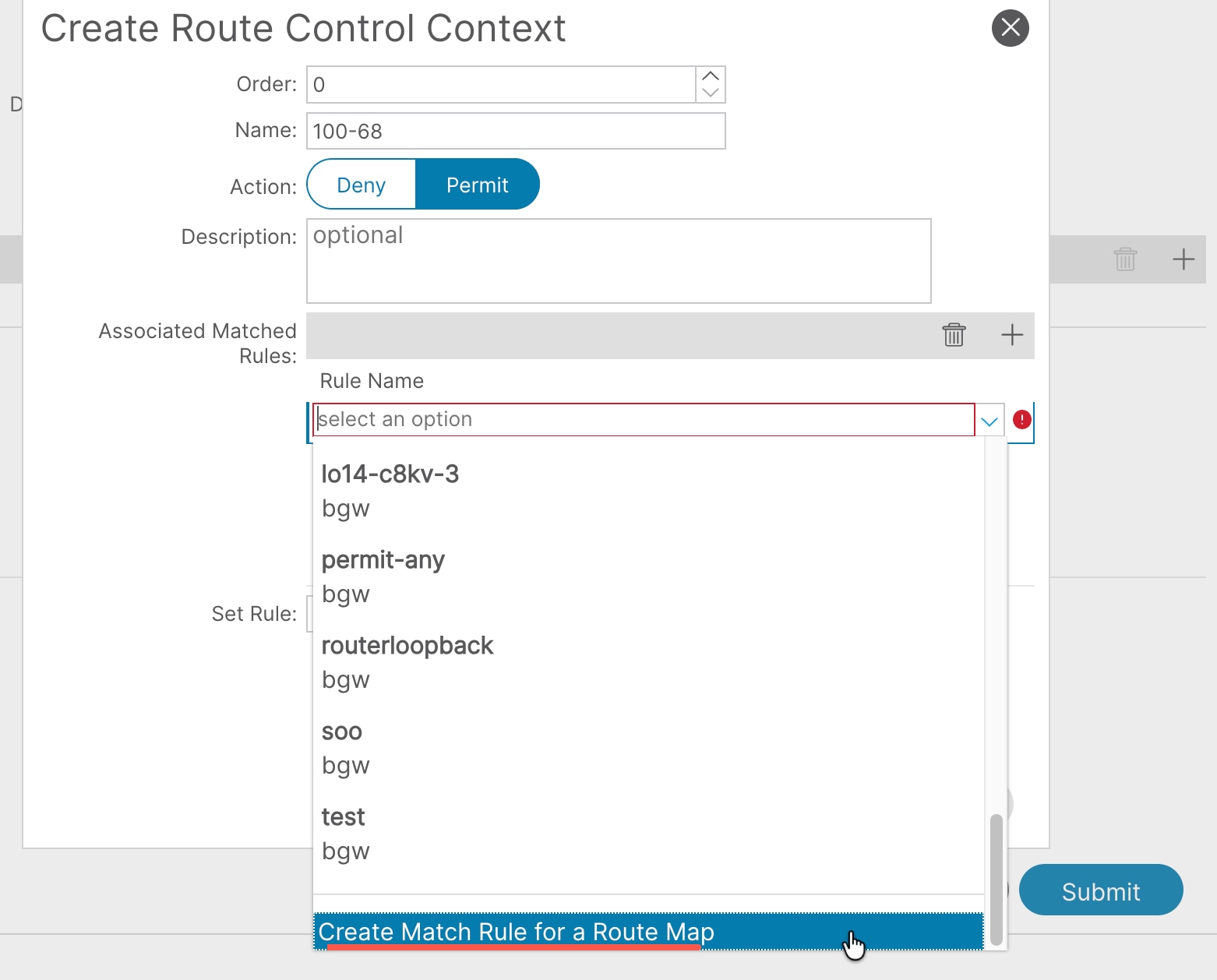
Figure 291. ACI Site 1 Add Match Prefix for a match rule
In the IP field, type 100.68.1.0/24, then click OK to complete.
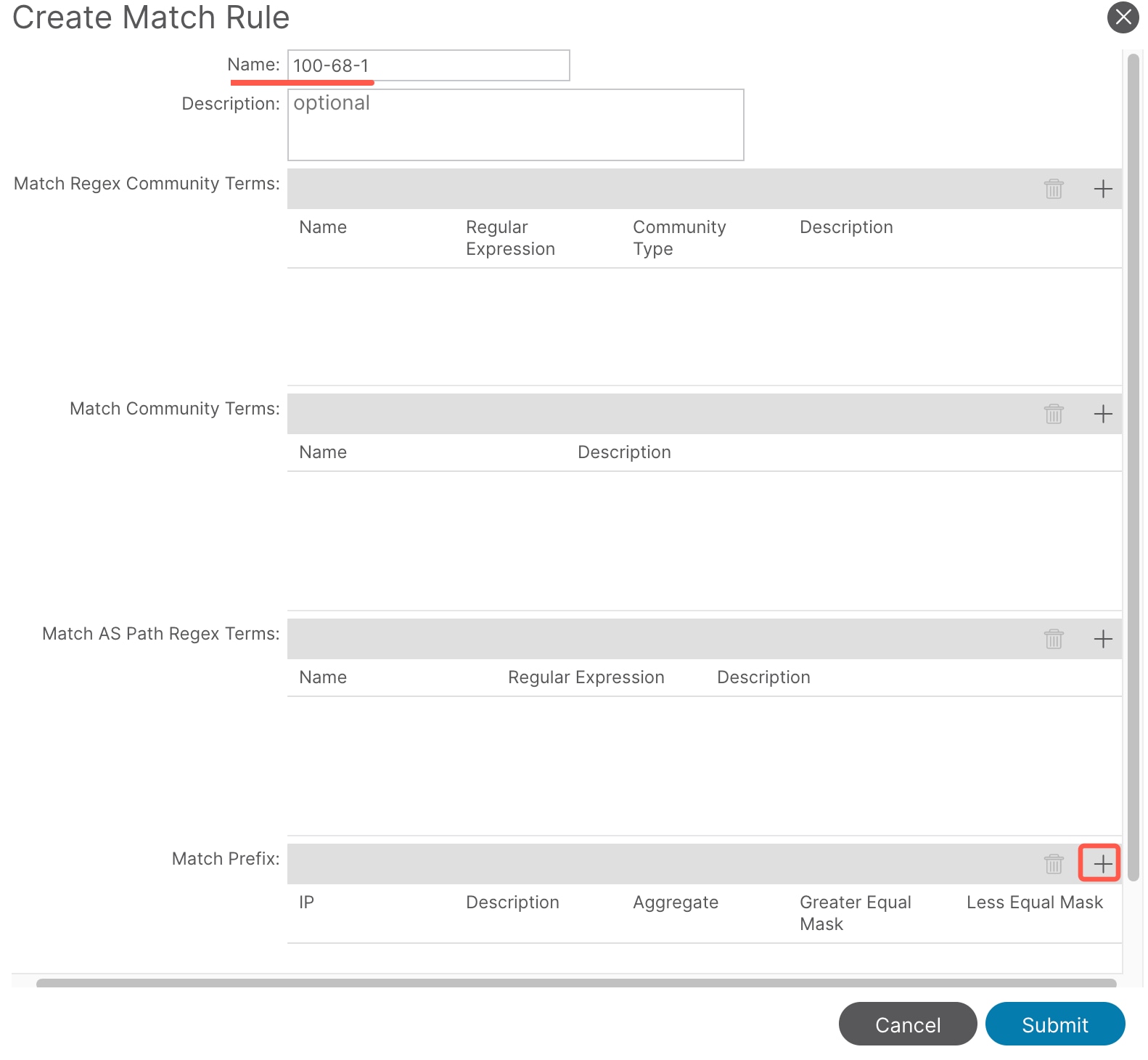
Figure 292. ACI Site 1 Route-map match rule add prefix
Click Submit to create a match rule.
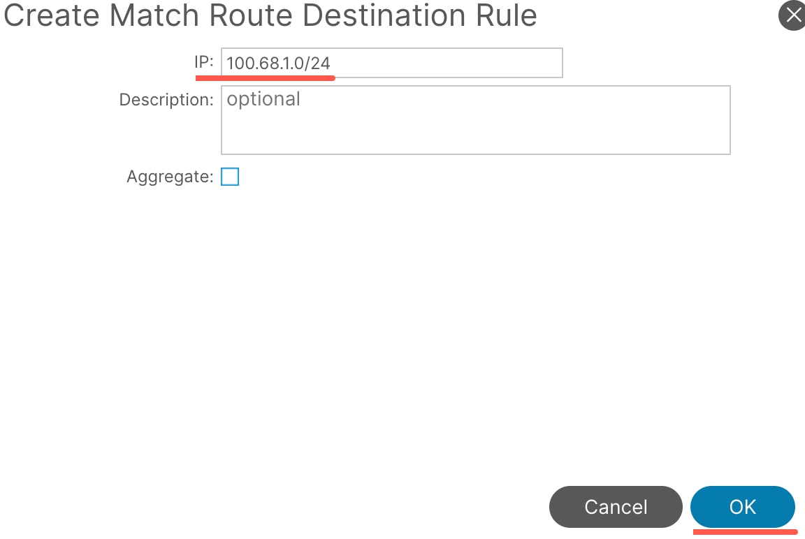
Figure 293. ACI Site 1 Create Match rule completion
Click Update to associate the match rule.
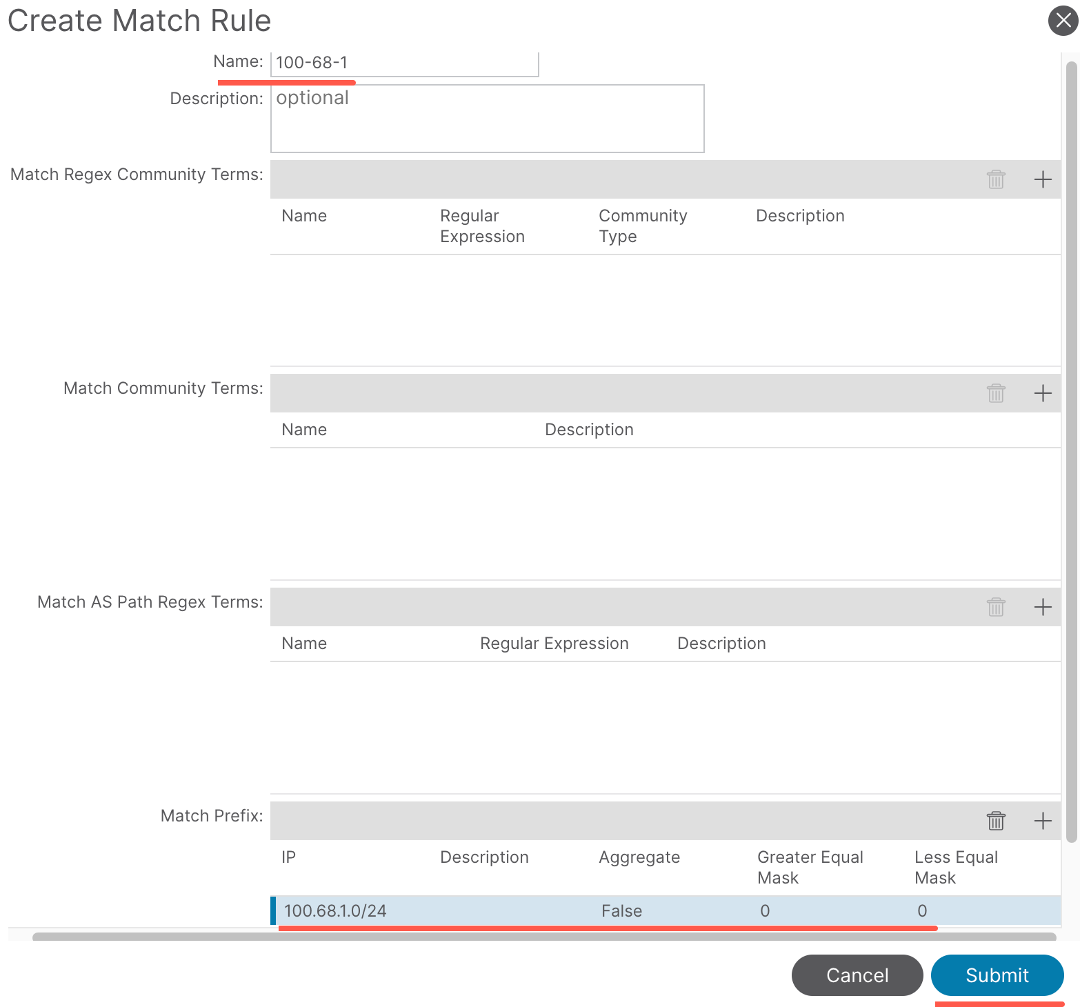
Figure 294. ACI Site 1 Create update to utilize matched rule
Click OK to complete the route-map route control context creation.
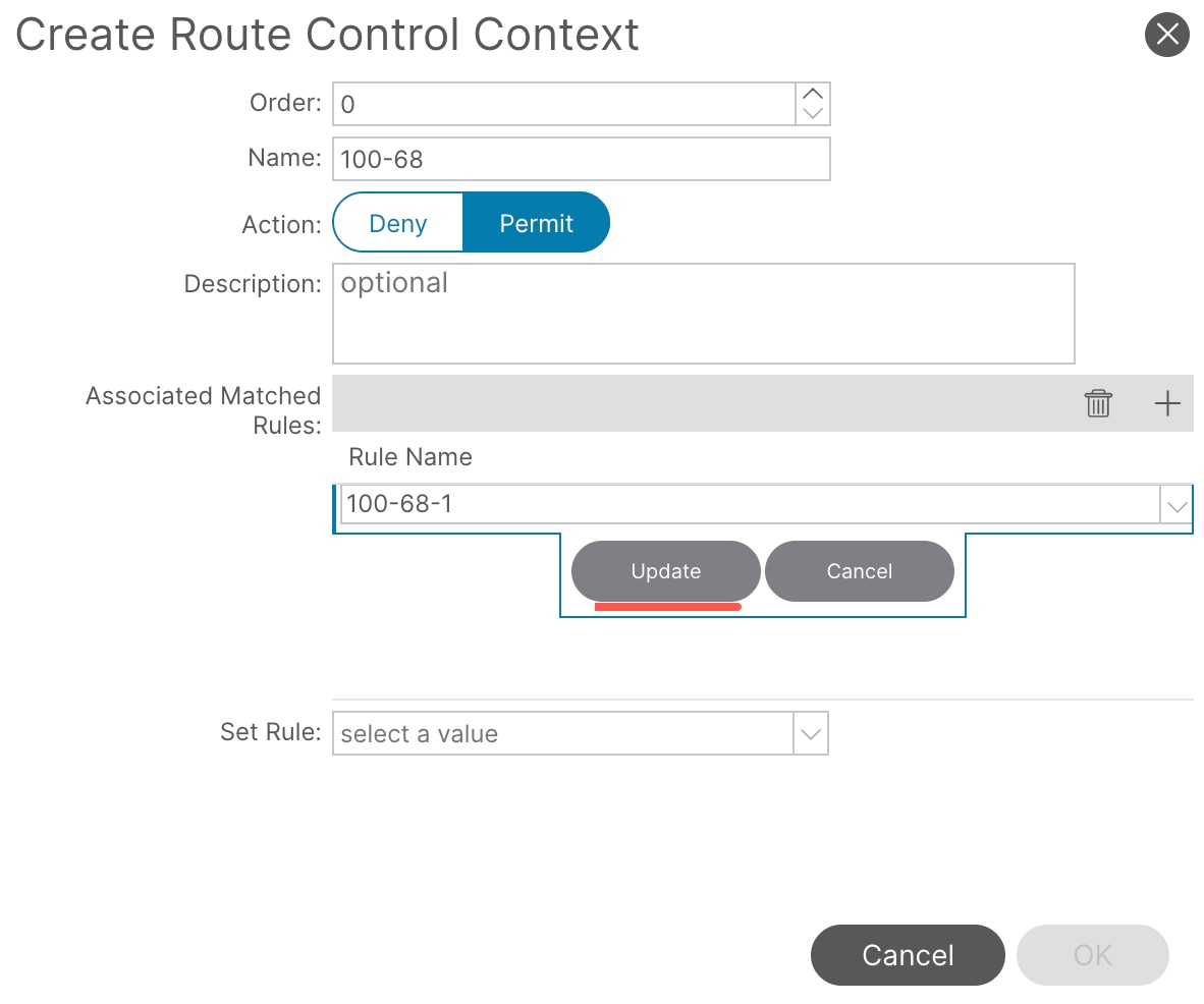
Figure 295. ACI Site 1 Click OK to complete route-map route control context creation
Click Submit to complete the route-map creation.
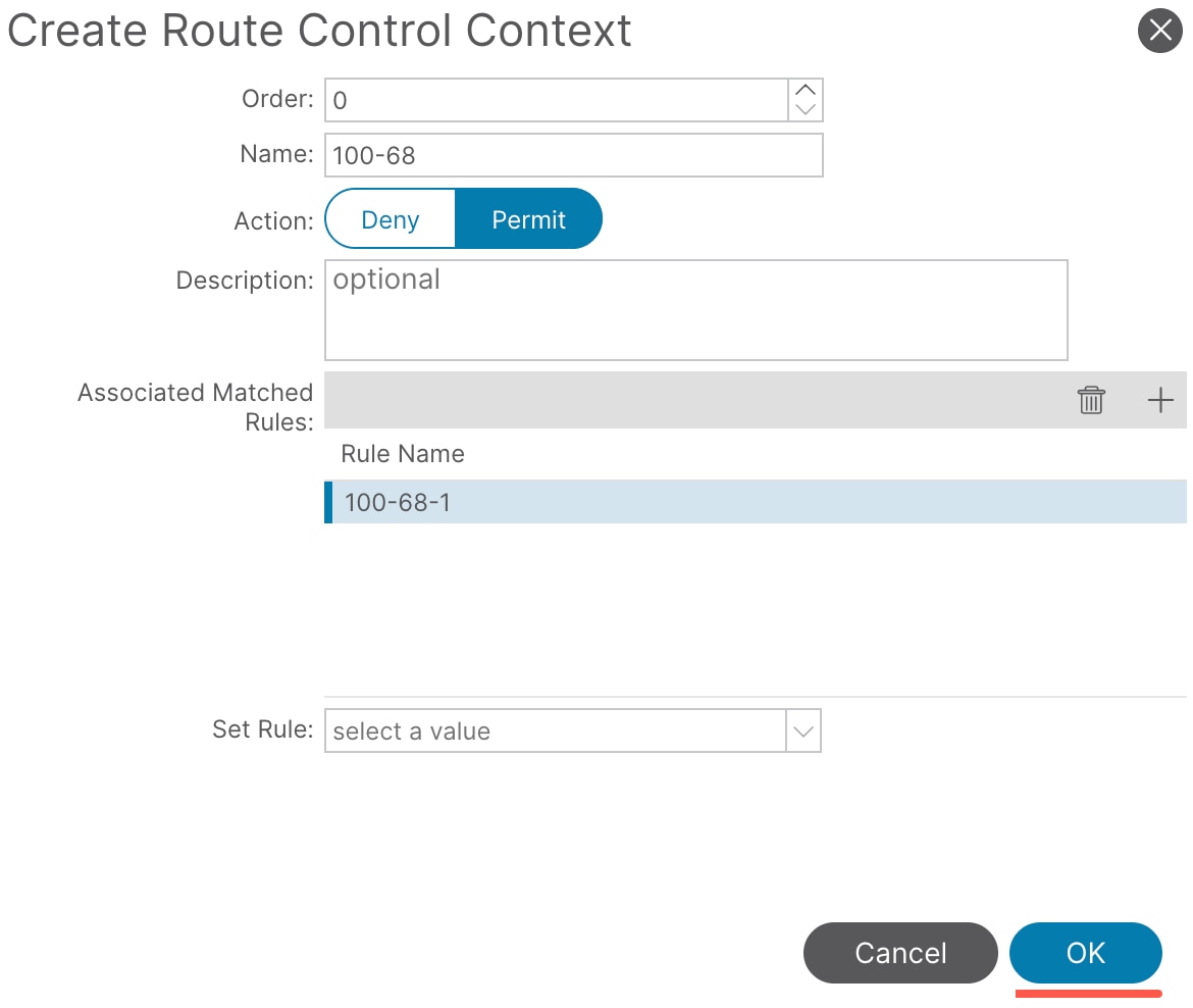
Figure 296. ACI Site 1 Submit to finish route-map creation
The newly created route-map appears under “Route map for import and export route control” sub-menu.
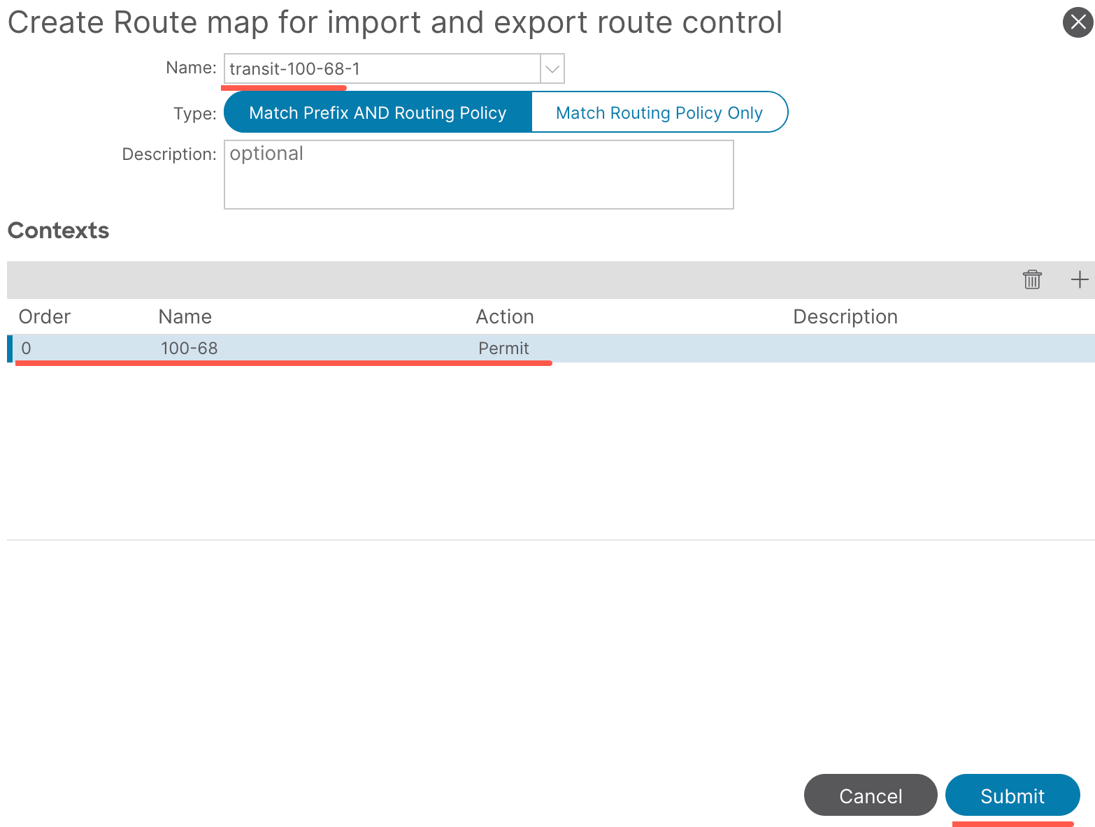
Figure 297. ACI Site 1 Route-map completion
To apply the route-map, navigate to external EPG -> Policy -> General then scroll down to Route Control Profile section and click “+”.
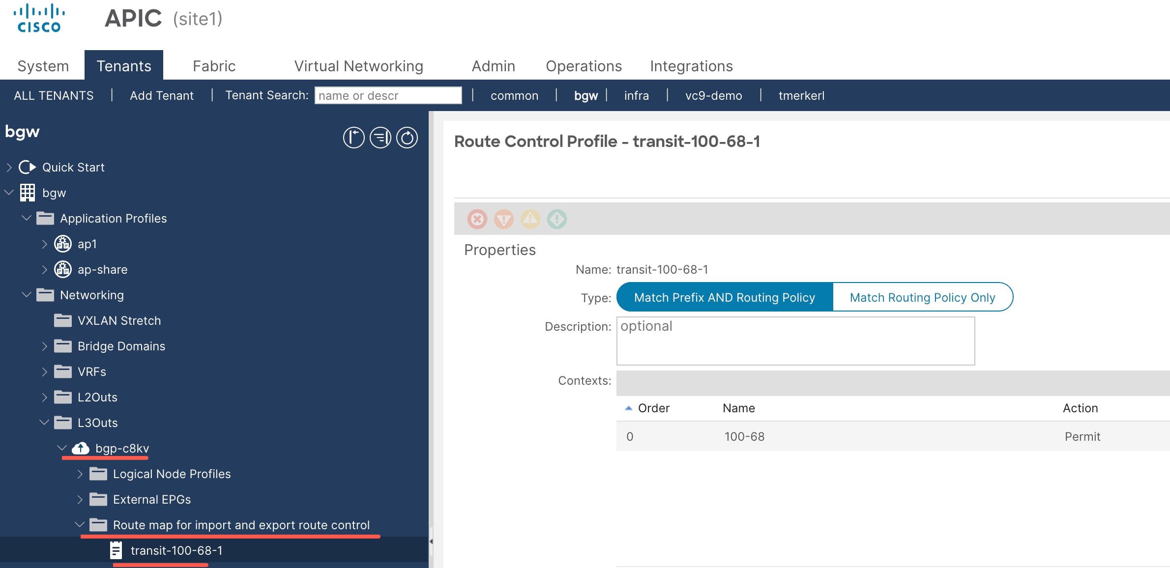
Figure 298. ACI Site 1 Apply route-map
In the Name drop-down list, choose “transit-100-68-1” which is the route-map created above, and choose Route Export Policy for Direction.
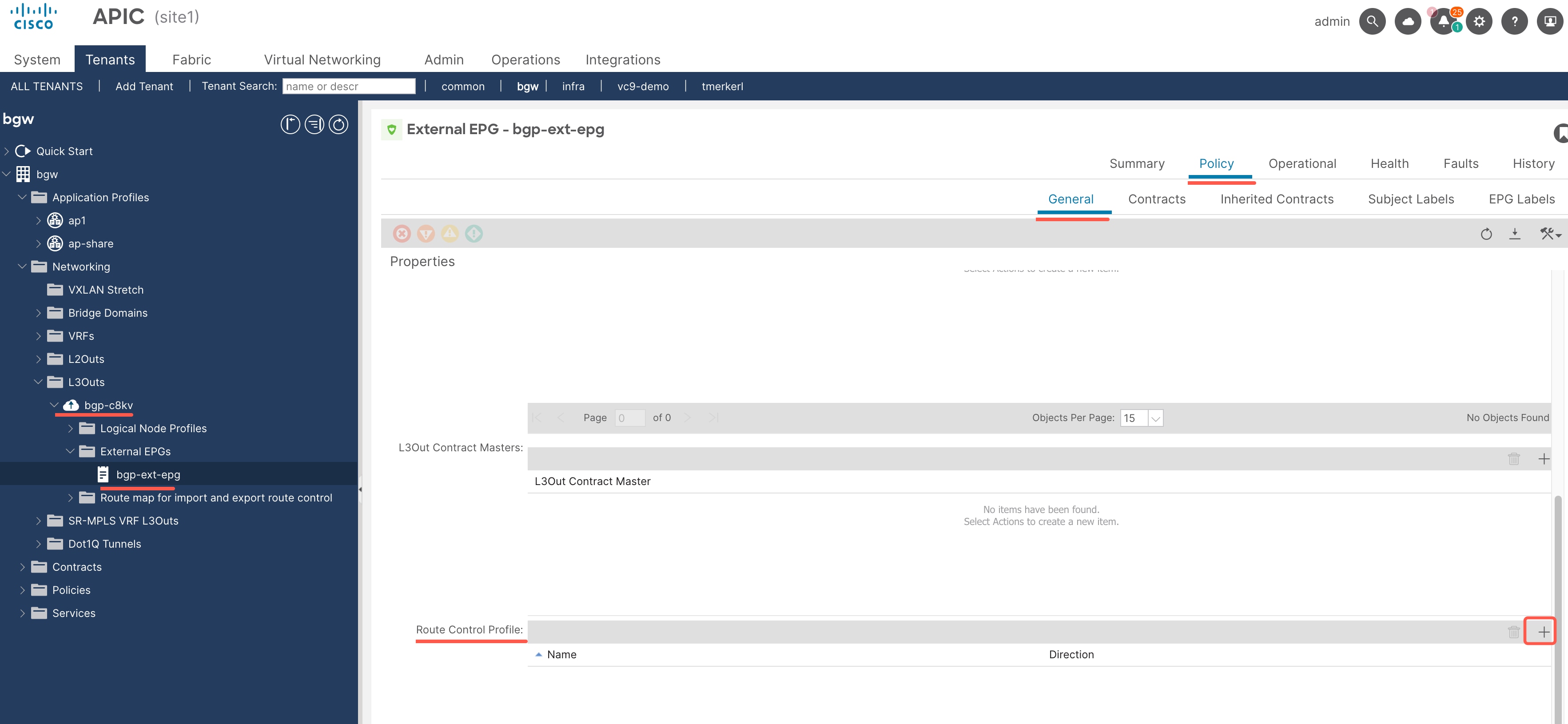
Figure 299. ACI Site 1 Apply route-map export direction
Verify that the external router in ACI Site 1 learns 100.68.1.0/24 from the ACI Site1 border leaf switch.
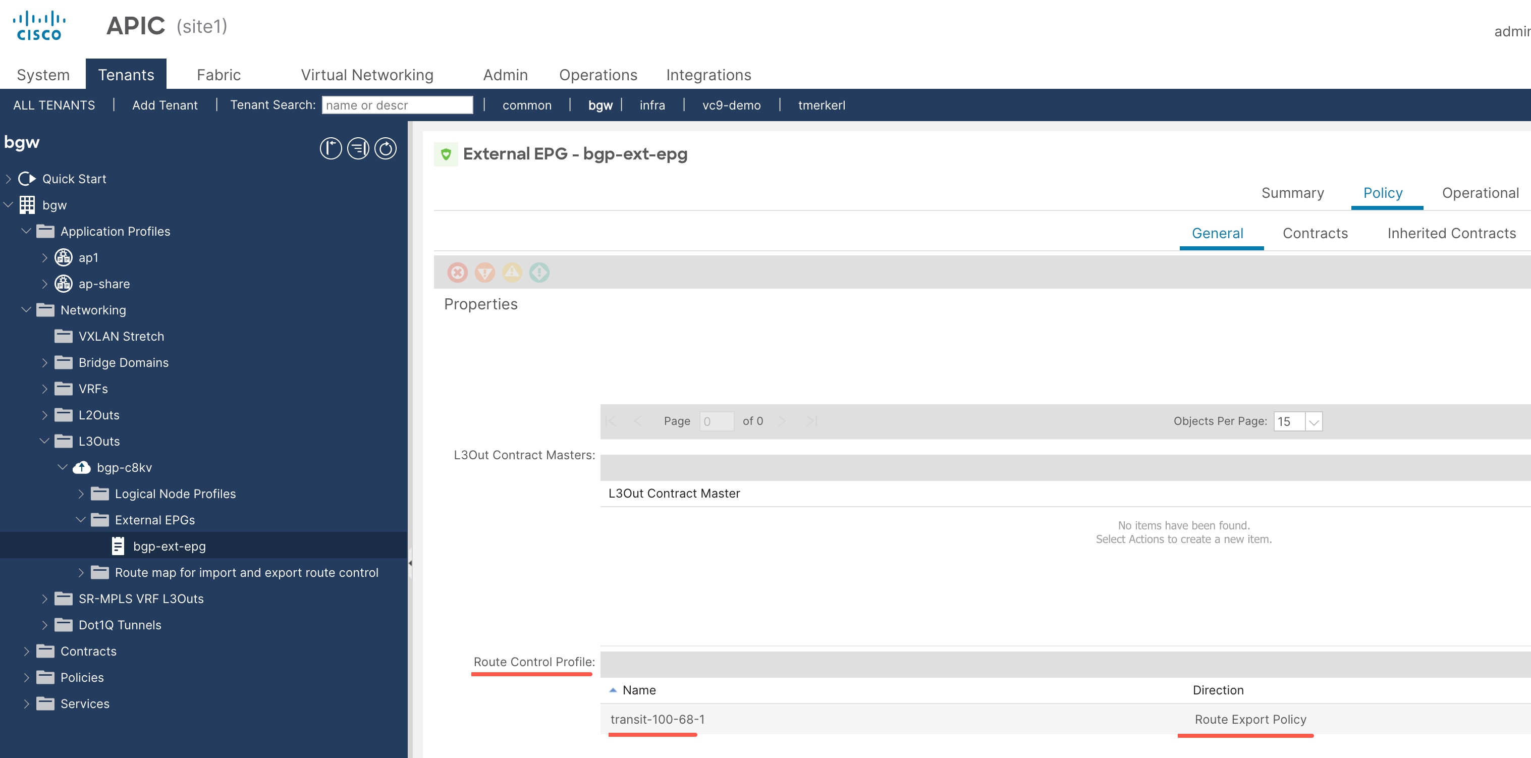
Figure 300. ACI Site 1 External router learns remote route
The configuration steps on ACI Site 2 are identical to those on ACI Site 1, with the exception that the match rule is o match subnet 100.64.1.0/24 that is the external subnet from ACI Site 1.
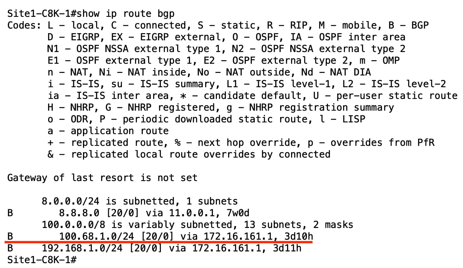
Figure 301. ACI Site 2 Match rule
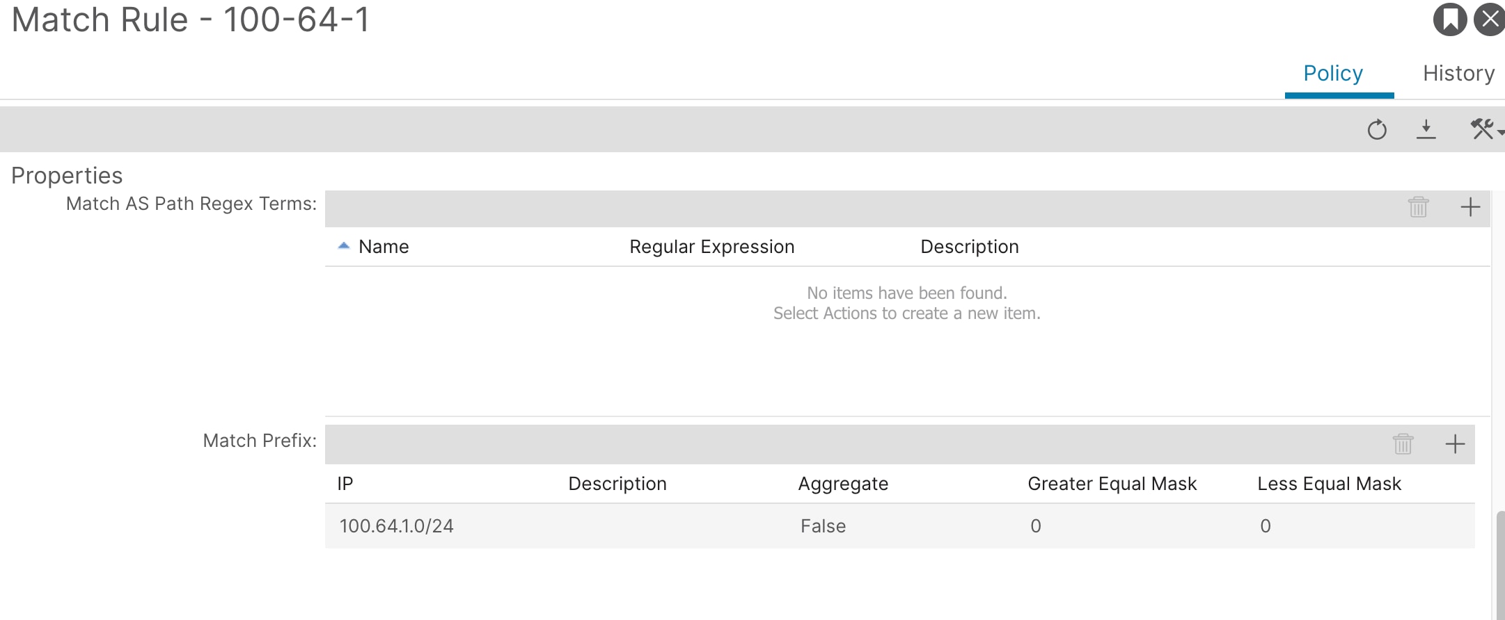
Figure 302. ACI Site 2 Apply route-map export direction
Verify that the external router in ACI Site 2 learns 100.64.1.0/24 from the ACI Site 2 border leaf switch.
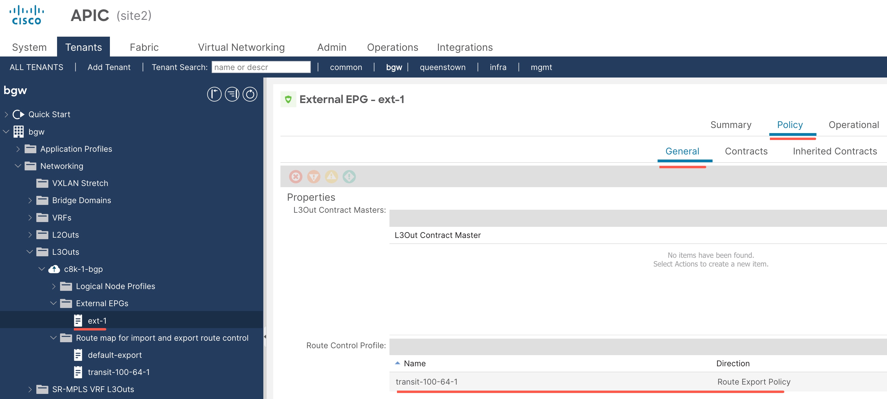
Figure 303. ACI Site 2 External router learns remote route
It is important to note that the default-export route map configured in Use Case 6: North-South Communication Across ACI sites with Non-stretched BD can also be leveraged for transit routing purposes. To utilize this capability, a new match context for subnet 100.64.1.0/24 must be added to the existing default-export route map configuration.
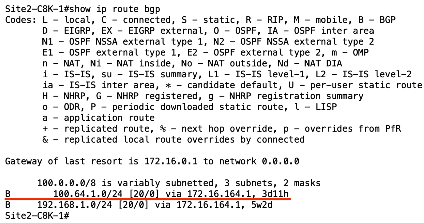
Figure 304. Add new context to default-export route-map
Follow similar step to add a new context.
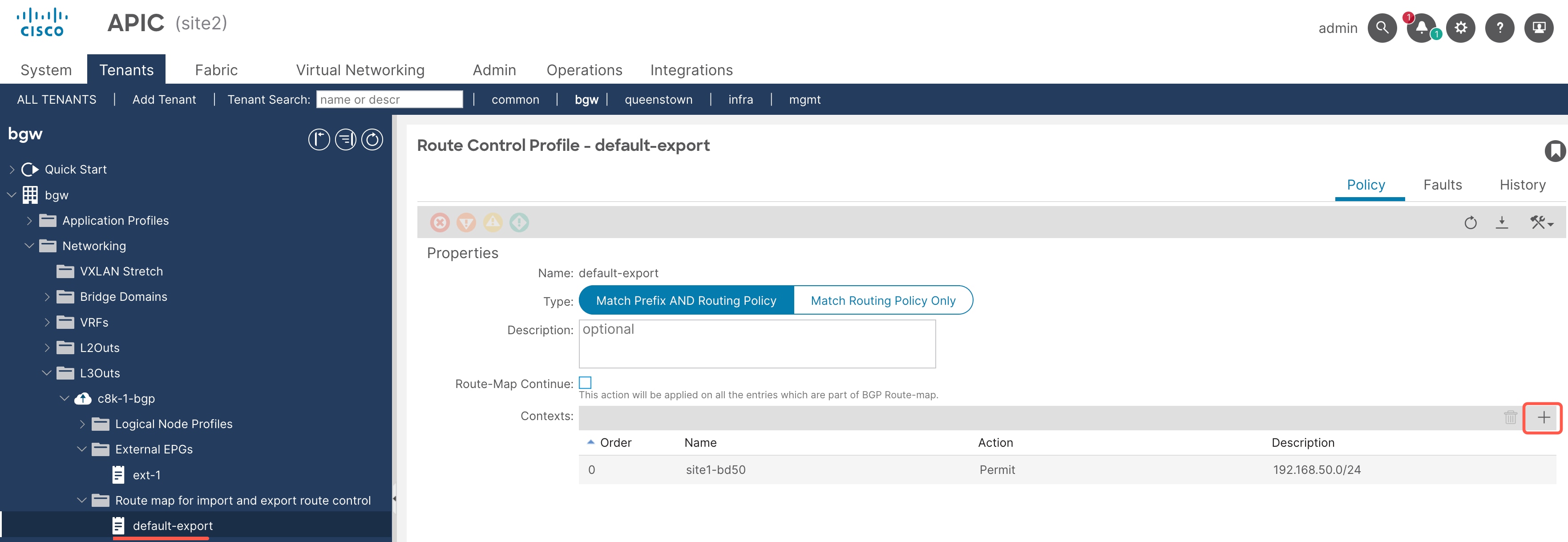
Figure 305. ACI Site 2 Add new context to default-export
Control Plane Verification
The following diagram illustrates the topology used in this verification.
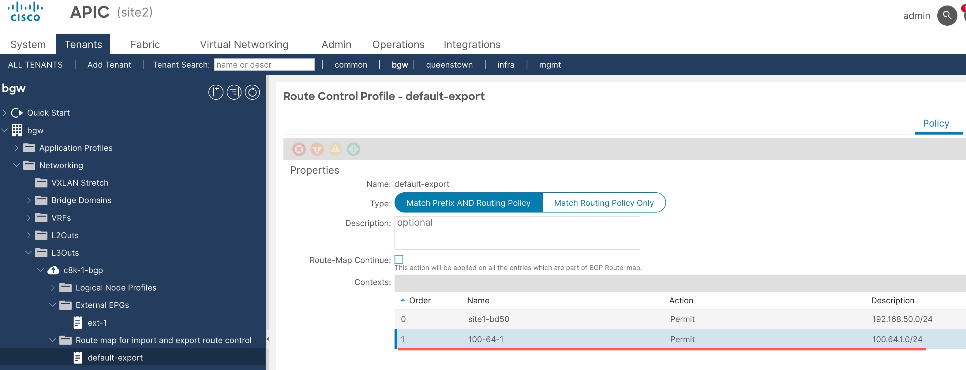
Figure 306. Transit Routing control plane verification
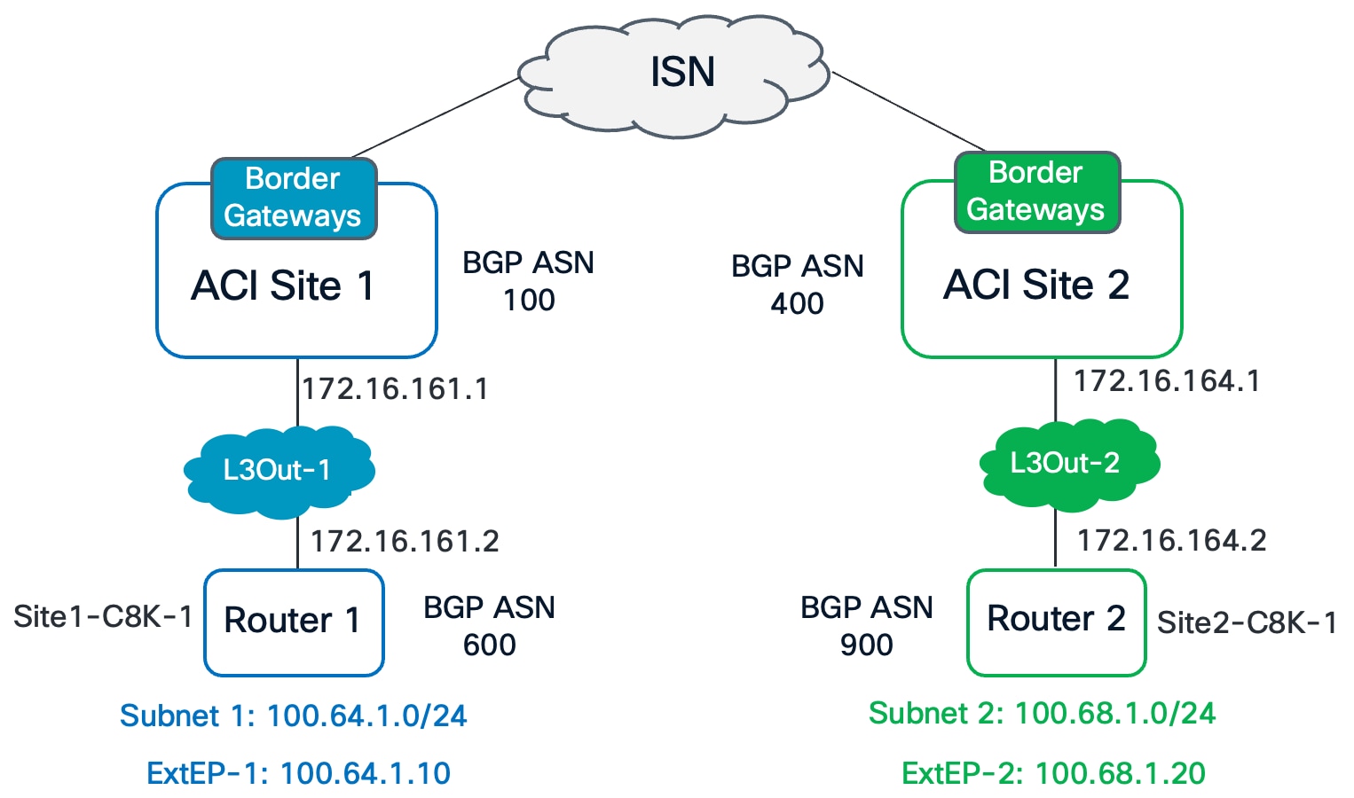
Figure 307. ESG ext-1 with normalized pcTag 8001
As this use case is analogous to Use Case 5 North-South Communication Across ACI Sites with Stretched BD , this section briefly reviews the routing table entries on the external routers on both sites. The expected outcome is that Router 1 (Site1-C8K-1) learns 100.68.1.0/24 and Router 2 (Site2-C8K-1) learns 100.64.1.0/24.
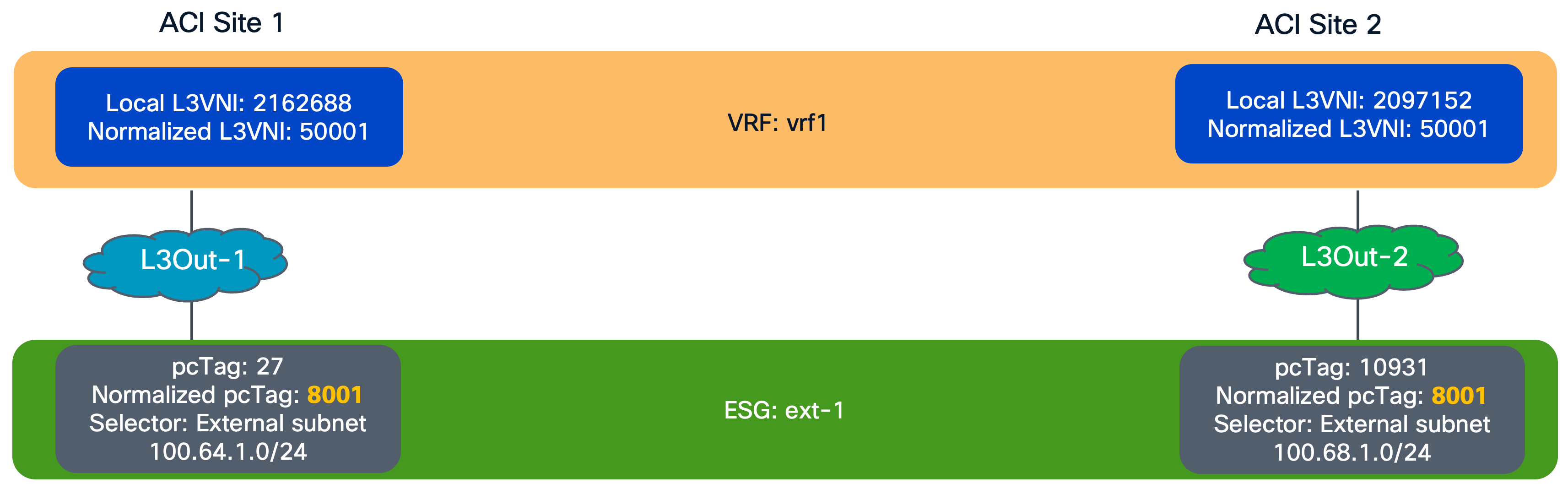
Figure 308. ACI Site 1 Router 1 learns route from Router 2
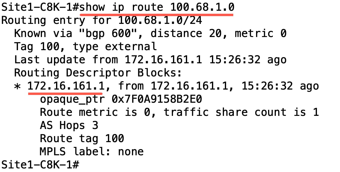
Figure 309. ACI Site 2 Router 2 learns route from Router 1
Data Plane Verification
The figure below illustrates a transit routing communication scenario. Communication occurs between ExtEP-1, an external endpoint reachable through the L3Out in ACI Site 1, and ExtEP-2, an external endpoint reachable through the L3Out in ACI Site 2.
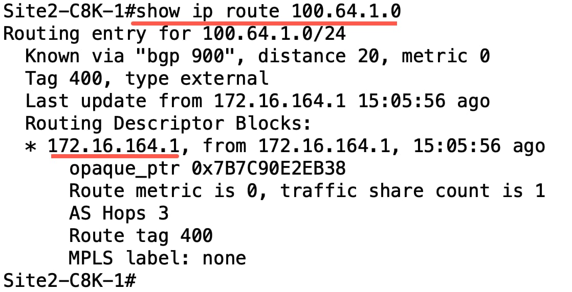
Figure 310. Transit Routing
Ping from an external endpoint ExtEP-1 (100.64.1.10) in ACI Site 1 to an external endpoint ExtEP-2 (100.68.1.20) in ACI Site 2. Communication works even without any contract between ESG ext-1 in ACI Site 1 and ESG ext-1 in ACI Site 2, the reason is that the same normalized pcTag 8001 is used for ESG ext-1 Site 1 and ESG ext-1 Site 2, which means that the external prefixes received from the local L3Out and from the other site are part of the same ESG.
The packet capture of the ICMP request from ExtEP-1 to ExtEP-2 confirms that the Layer 3 (VRF) Normalized VNI is used in the VXLAN header for inter-site data plane forwarding.
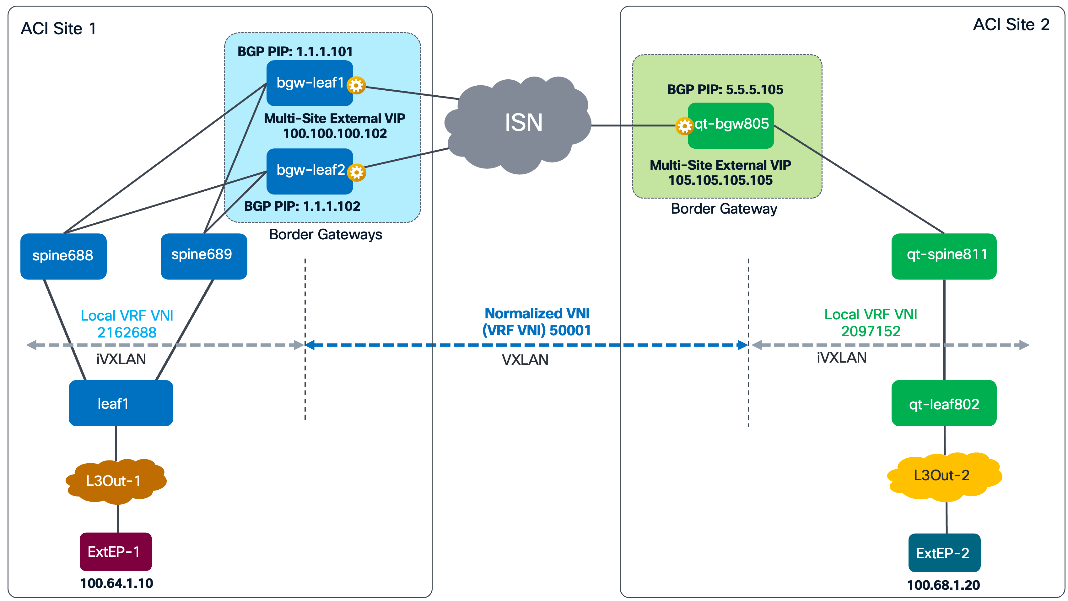
Figure 311. ICMP request from ExtEP-1 (100.64.1.10) to ExtEP-2 (100.68.1.20)
The packet capture of the ICMP reply from ExtEP-2 to ExtEP-1 confirms that the Layer 3 (VRF) Normalized VNI is used in the VXLAN header for inter-site data plane forwarding.
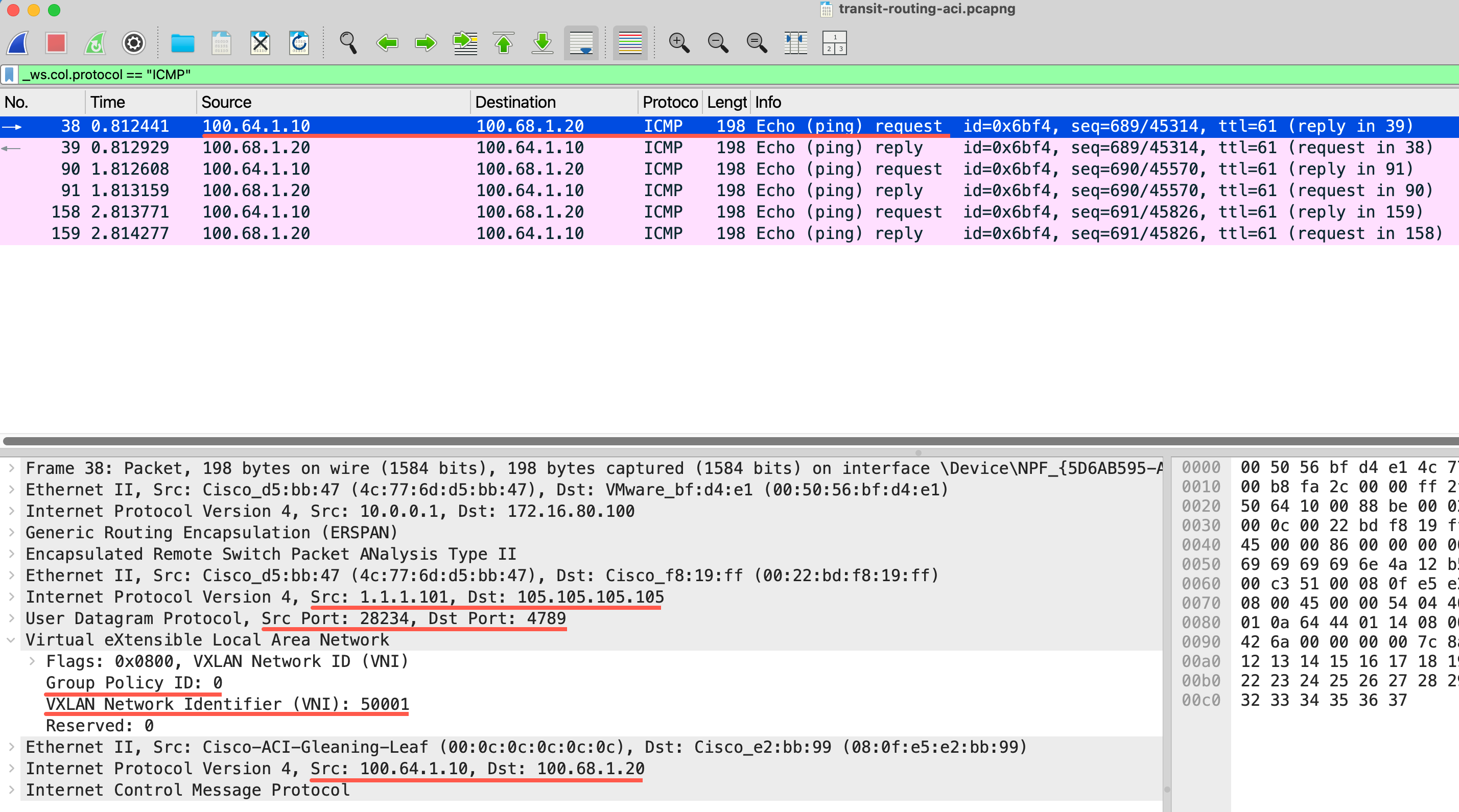
Figure 312. ICMP reply from ExtEP-2 (100.68.1.20) to ExtEP-1 (100.64.1.10)
The figure below illustrates the policy enforcement locations for traffic from an external endpoint in ACI Site 1 to an external endpoint in ACI Site 2.
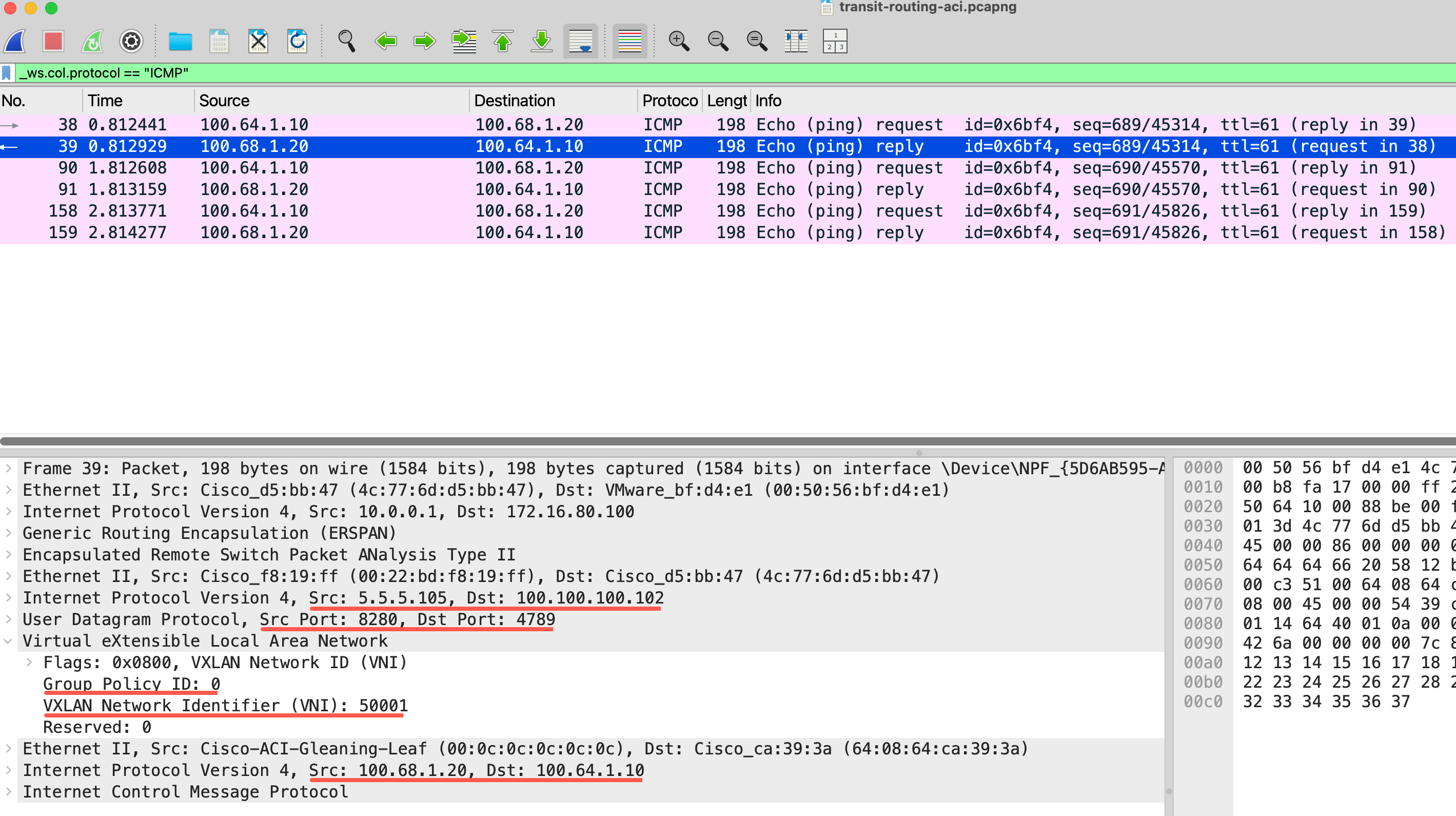
Figure 313. Policy enforcement Transit Routing across sites
Policy is enforced at the Border Gateways at both ACI sites in both directions, as the Border Gateways retain the route and the associated pcTag through BGP EVPN Type-5 route exchange. Conversely, the compute leaf receives the route but resets the pcTag to 1, resulting in traffic being forwarded without contract enforcement.
Use Case 8: Design Considerations with Overlapping Prefixes in Multi-L3Out Deployments
In this use case, each ACI site maintains its own dedicated L3Out connection to the external WAN.
The figure below illustrates the design. The external routers (Router 1 In ACI Site 1 and Router 2 in ACI Site 2) establish BGP sessions with the Core‑WAN router (BGP ASN 800), which serves as the gateway to the external WAN. The Core‑WAN router advertises 108.0.0.0/24 to both ACI sites. As a result, both ACI sites learn the same prefixes through their local L3Outs as well as through the other site, which requires a traffic‑engineering for path‑selection and failover to ensure optimal forwarding behavior, efficient WAN‑link utilization, and seamless recovery if the local L3Out becomes unavailable.
It is important to note that, with the introduction of Core-WAN router in this specific design, the two ACI sites no longer serve as transit points between Router 1 and Router 2. For example, 100.64.1.0/24 behind Router 1 is now advertised through Core-WAN router to Router 2 via BGP. In the reverse direction, 100.68.1.0/24 behind Router 2 is advertised through Core-WAN router to Router 1 via BGP.
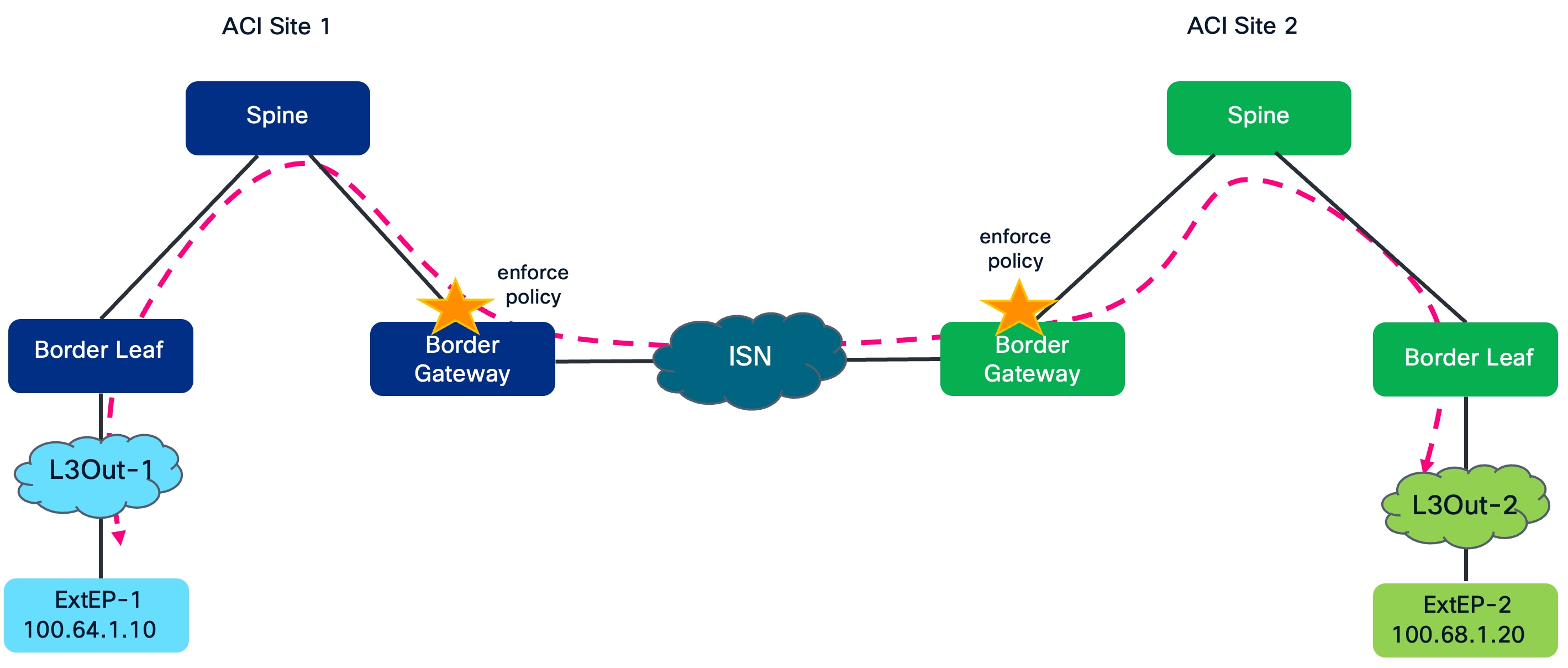
Figure 314. Overlapping Prefix multiple L3Outs
Create common prefix ESG and apply policy
The ESG ext-core is configured on both ACI sites using the same External Subnet Selector and the normalized pcTag to maintain policy consistency. In this use case, under normal conditions when both L3Outs are operational, both ACI Sites learn the same external prefix (108.0.0.0/24) from the Core-WAN. It is required to configure the “External Subnet Selector” on both ACI Sites to match the subnet 108.0.0.0/24 for the ESG ext-core to classify traffic correctly. This configuration allows traffic originating from the local L3Out to be recognized and permitted once the contract between esg1 and ext-core is applied.
To permit traffic between EP-1 in esg1 to EP-3 in esg-ext-core, create a contract named esg-ext-core, between esg1 and ext-core. The following figures are ESG and contract configuration in both ACI sites.
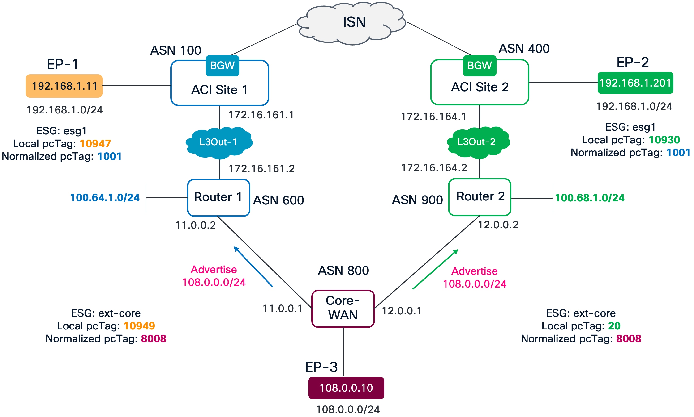
Figure 315. ACI Site 1 ESG ext-core
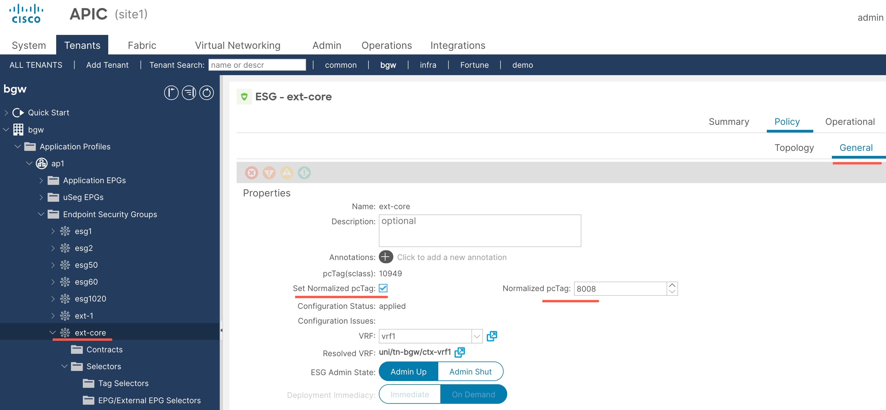
Figure 316. ACI Site 1 ESG ext-core External Subnet Selector
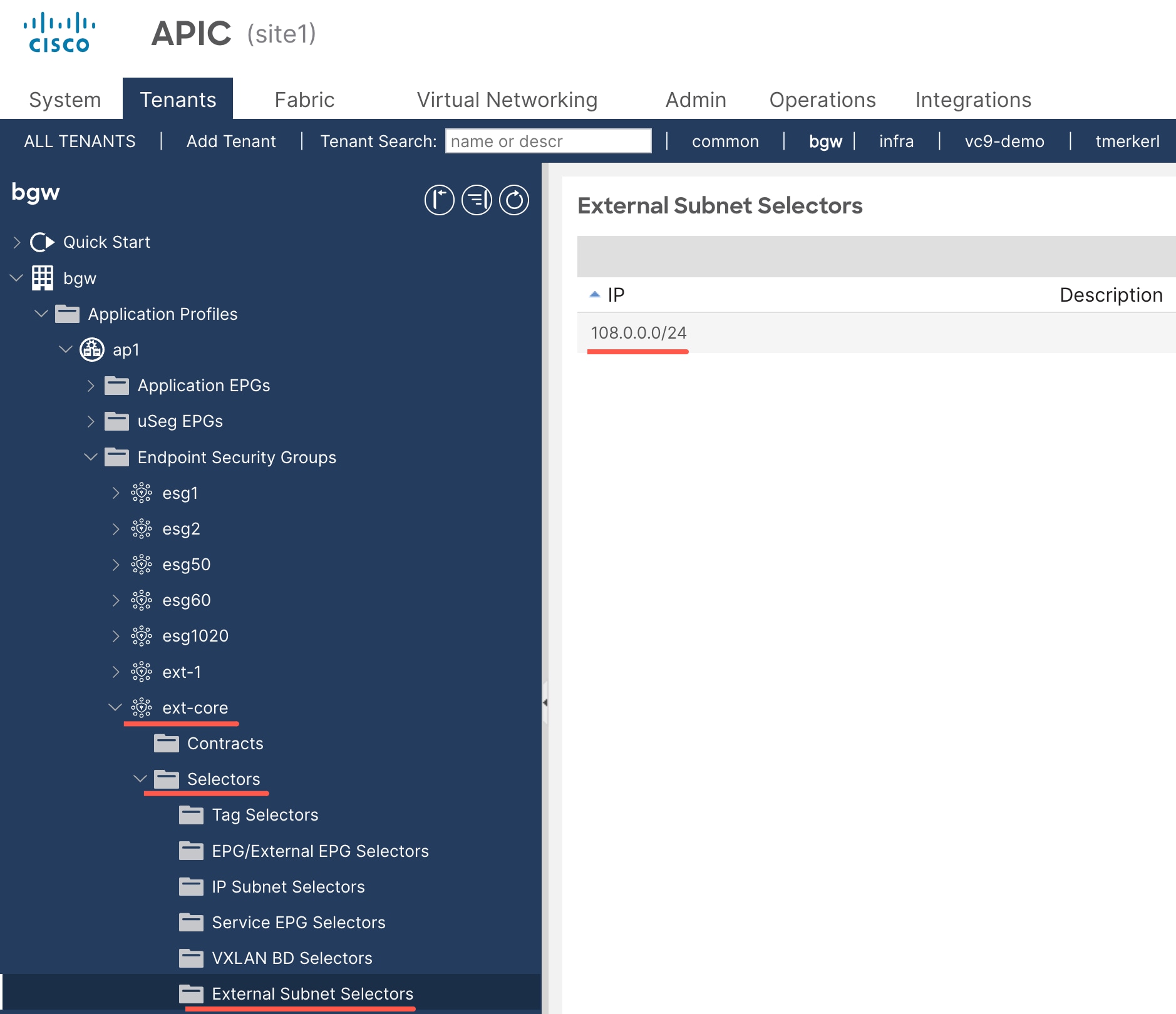
Figure 317. ACI Site 1 ESG ext-core contract provider
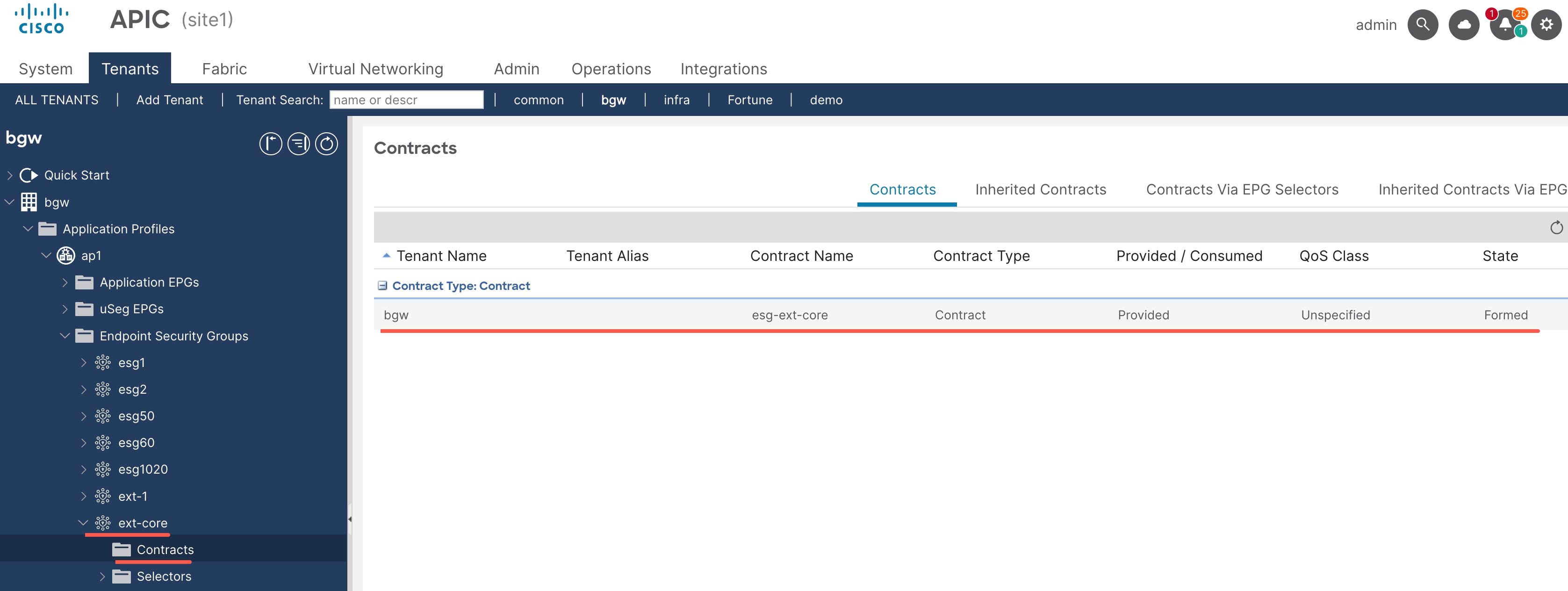
Figure 318. ACI Site 1 ESG esg1 contract consumer
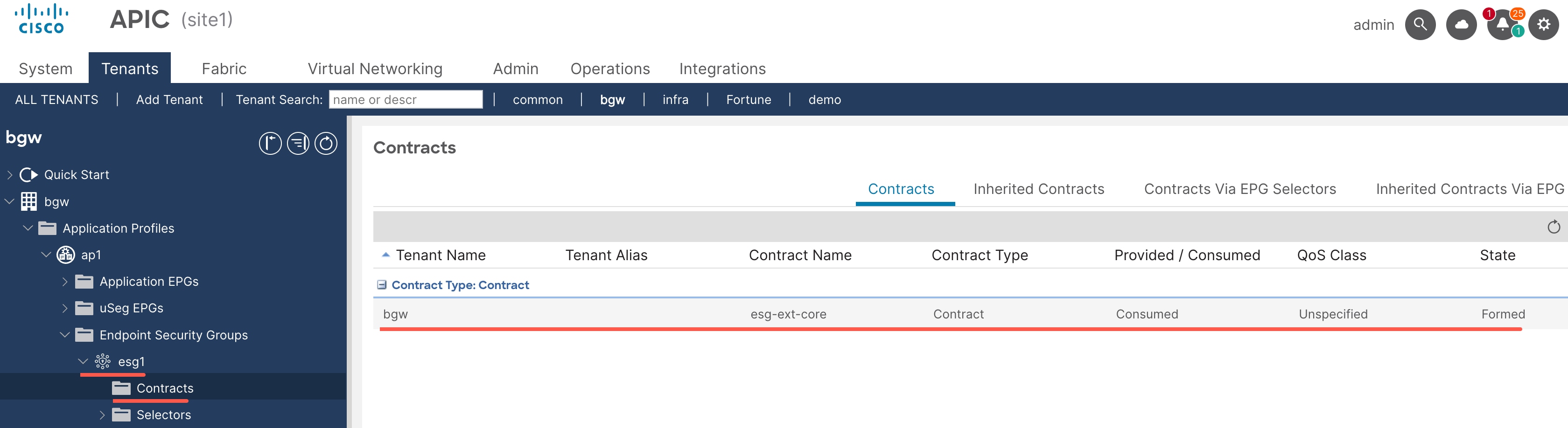
Figure 319. ACI Site 2 ESG ext-core
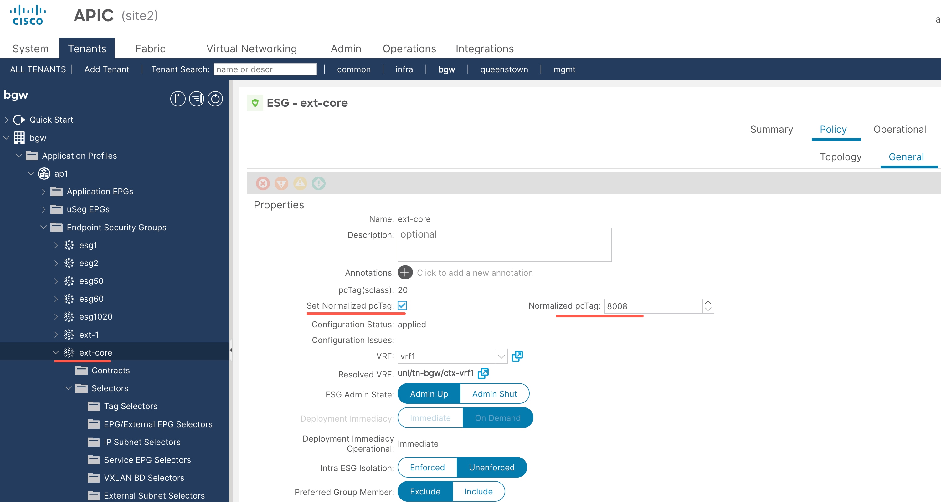
Figure 320. ACI Site 2 ESG ext-core External Subnet Selector
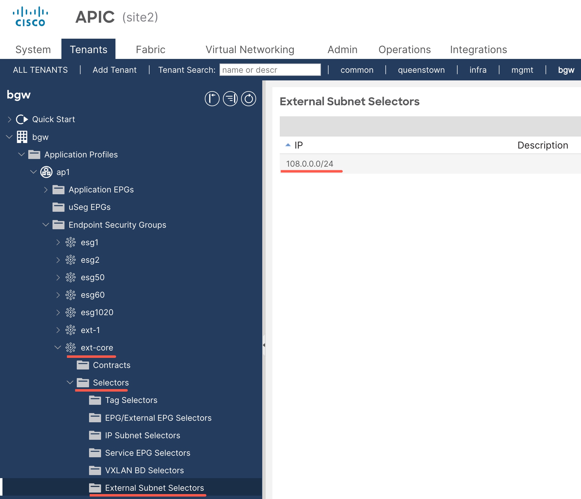
Figure 321. ACI Site 2 ESG ext-core contract provider
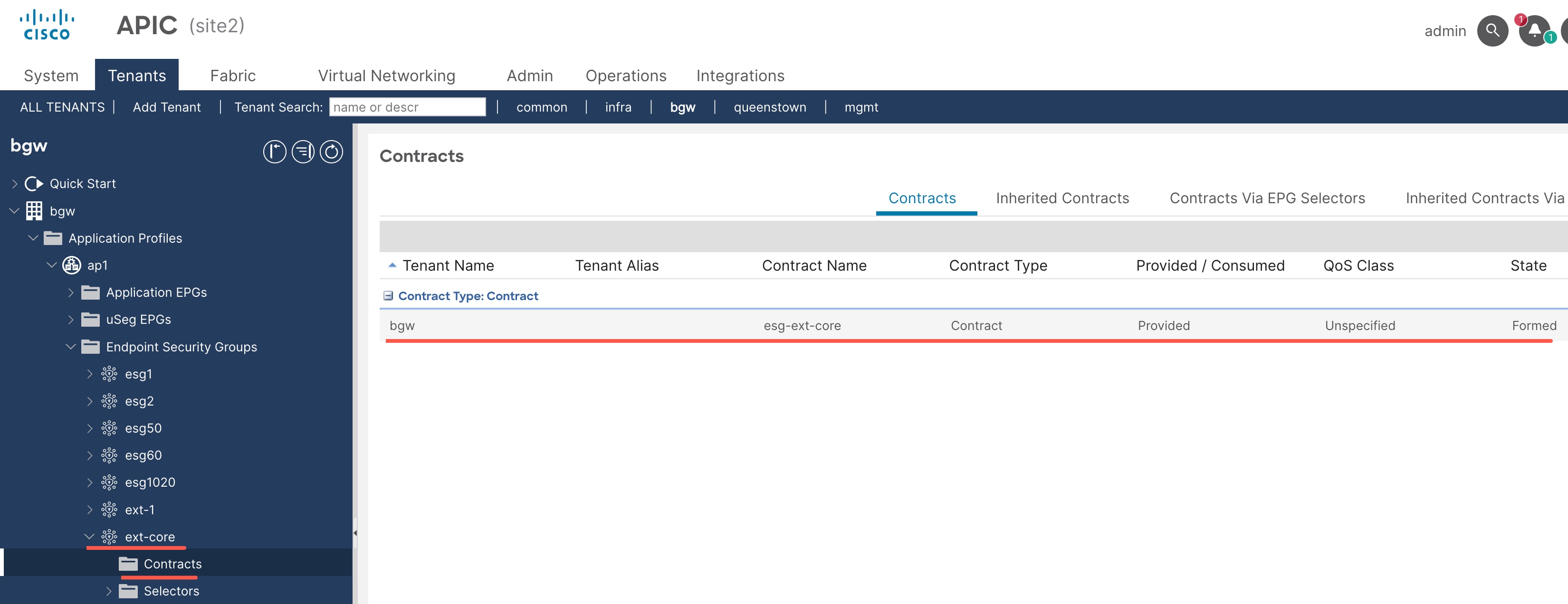
Figure 322. ACI Site 2 esg1 contract consumer
By default, in an ACI fabric, a local L3Out is always preferred for outbound communication from an ACI local endpoint to an external network. As a result, outbound traffic is deterministic whereas inbound traffic from an external client (108.0.0.10 in this example) to an ACI local endpoint might not be deterministic depending on how to advertise the ACI internal subnet to the external network.
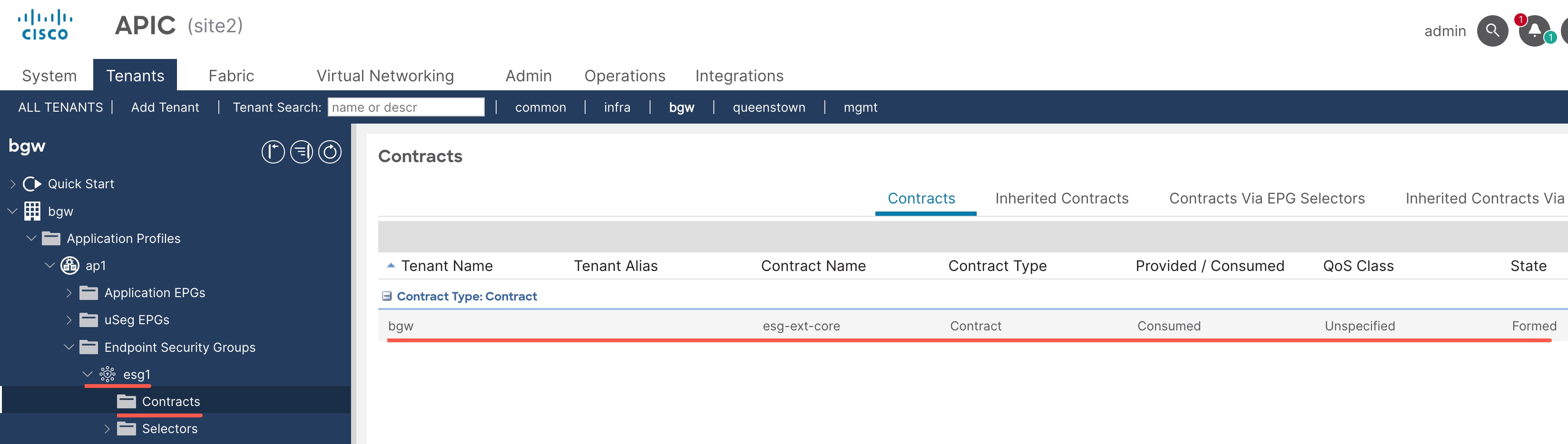
Figure 323. Outbound flow from ACI Site connected endpoint to external
The following is a BGP configuration example on Core-WAN router:
Core-WAN#show run | sec bgp
router bgp 800
bgp log-neighbor-changes
neighbor 11.0.0.2 remote-as 600
neighbor 11.0.0.2 fall-over bfd
neighbor 12.0.0.2 remote-as 900
neighbor 12.0.0.2 fall-over bfd
!
address-family ipv4
network 0.0.0.0
network 8.8.8.0 mask 255.255.255.0
network 108.0.0.0 mask 255.255.255.0
neighbor 11.0.0.2 activate
neighbor 12.0.0.2 activate
exit-address-family
The BGP table on Core-WAN router shows two entries for the same destination prefix 192.168.1.0/24 (BD1 subnet), with next-hops 11.0.0.2 and 12.0.0.2 corresponding to Router 1 (Site 1) and Router 2 (Site 2). Following the default BGP best path selection process, only one route is selected as the best path. In this case, the route via 12.0.0.2 is selected as it happens to be the oldest route. Although BGP multipath can be enabled to install multiple equal-cost paths for load balancing, it does not address suboptimal inbound traffic to ACI Sites.
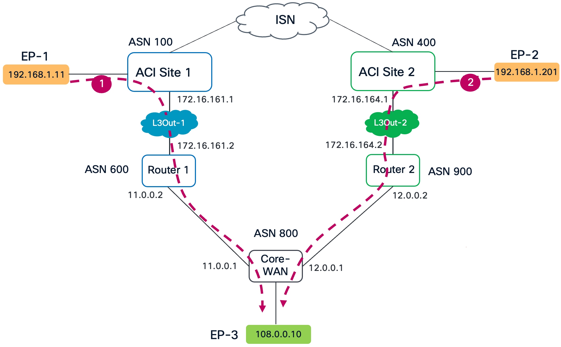
Figure 324. Core-WAN BGP Table
The following is the routing table for 192.168.1.0/24 (BD-1 subnet) on Core-WAN, which uses 12.0.0.2 (Router 2) as the next hop.
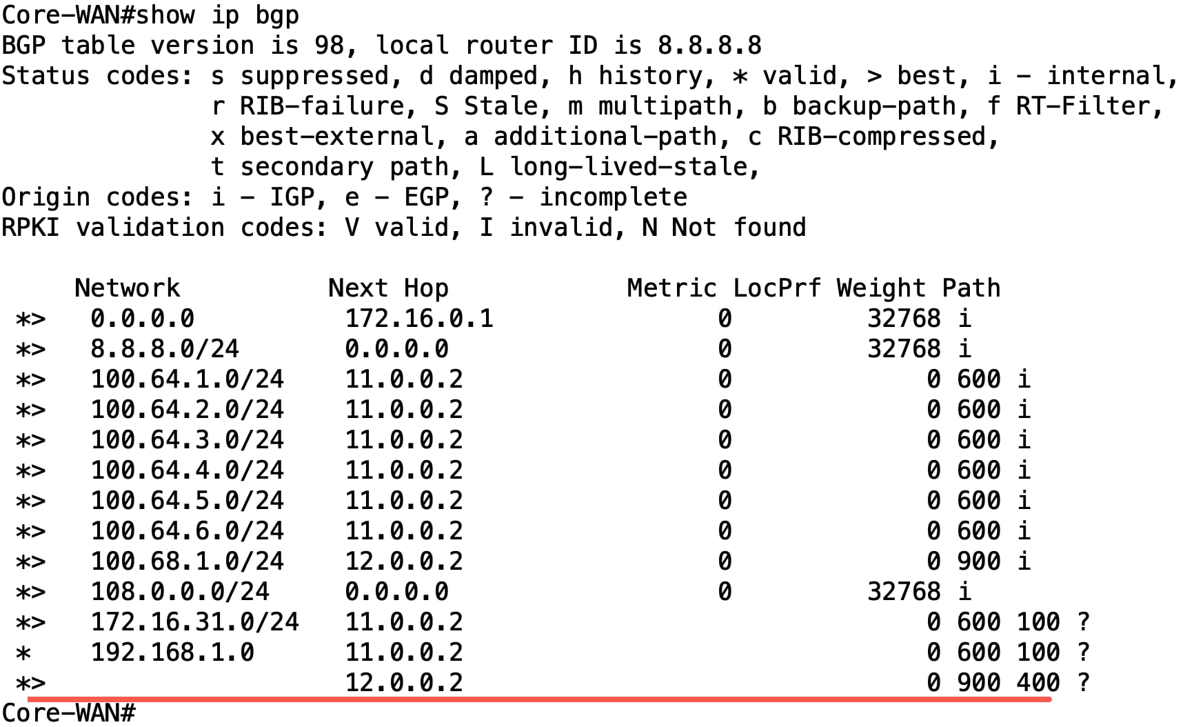
Figure 325. Core-WAN Routing Table
Based on the routing table on Core-WAN, inbound traffic from the external endpoint behind Core-WAN is always forwarded through Router 2 connected to ACI Site 2, regardless of the actual location of the destination endpoint in 192.168.1.0/24. Moreover, the inbound traffic path is not deterministic. For example, if Router 2 is reloaded or the L3Out-2 BGP session is reset, the Core-WAN router will shift its best path next-hop to Router 1, redirecting all inbound traffic from the external WAN to 192.168.1.0/24 accordingly. This non-deterministic inbound traffic behavior introduces challenges in deployments where a stateful device resides between the Core-WAN router and the ACI sites, as such stateful devices may drop asymmetric traffic. Furthermore, with this default configuration, one of the L3Out connections remains consistently idle for inbound traffic, resulting in suboptimal utilization of the available WAN links.
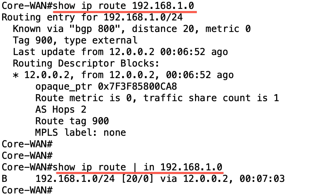
Figure 326. Non-optimal incoming flow
Inbound Traffic Flow Optimization
To optimize inbound traffic from the external WAN to ACI local endpoints, host-based routing can be enabled on both ACI sites. By configuring the “Advertised Host Route” option on bd1 in both ACI Site 1 and ACI Site 2, each site advertises /32 host routes (/128 for IPv6) for every active endpoint in bd1 to Core-WAN router via their respective local L3Outs.
As a result, Core-WAN router learns /32 host routes from both ACI sites simultaneously. Since each /32 host route is advertised exclusively by the site where the endpoint resides, Core-WAN router can accurately determine the optimal next-hop for each destination endpoint. This ensures that inbound traffic from the external WAN is always forwarded to the correct ACI site, regardless of endpoint location, eliminating the non-deterministic inbound traffic behavior described previously.
When enabling host-based routing, it is important to carefully consider the routing table capacity of all external devices along the path between the ACI sites and Core-WAN router. Intermediate routers, such as Router 1 and Router 2, will also learn and carry the /32 host routes in their routing tables. As the number of active endpoints grows, the volume of advertised host routes increases proportionally, which may exceed the routing table capacity of intermediate devices if not properly planned.
The following figures show the bd1 configuration in both ACI sites.
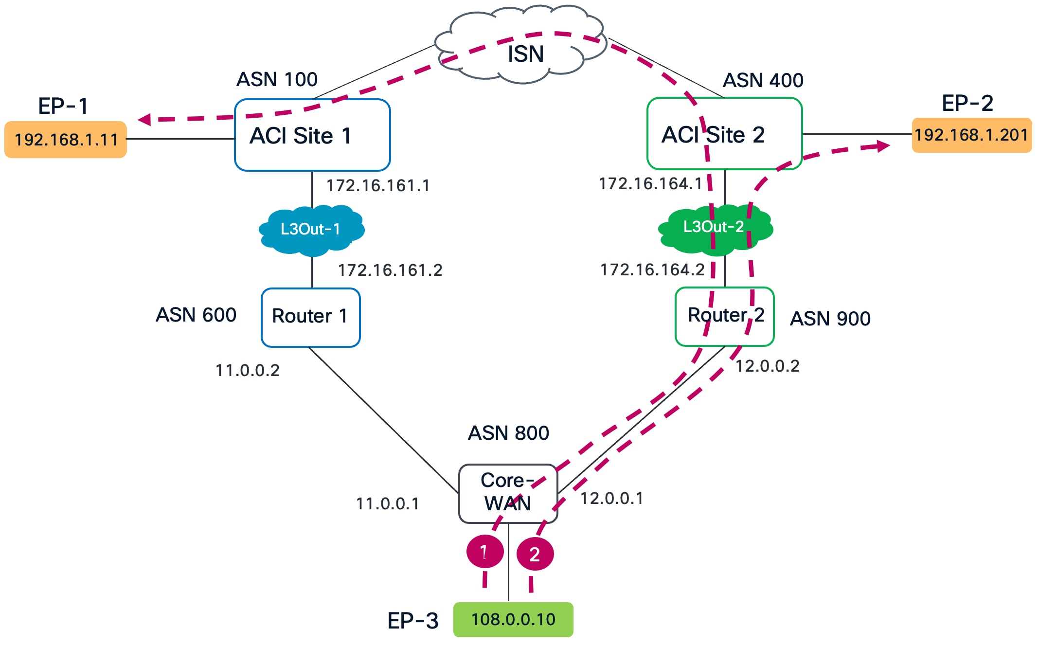
Figure 327. ACI Site 1 bd1 Advertise Host Routes
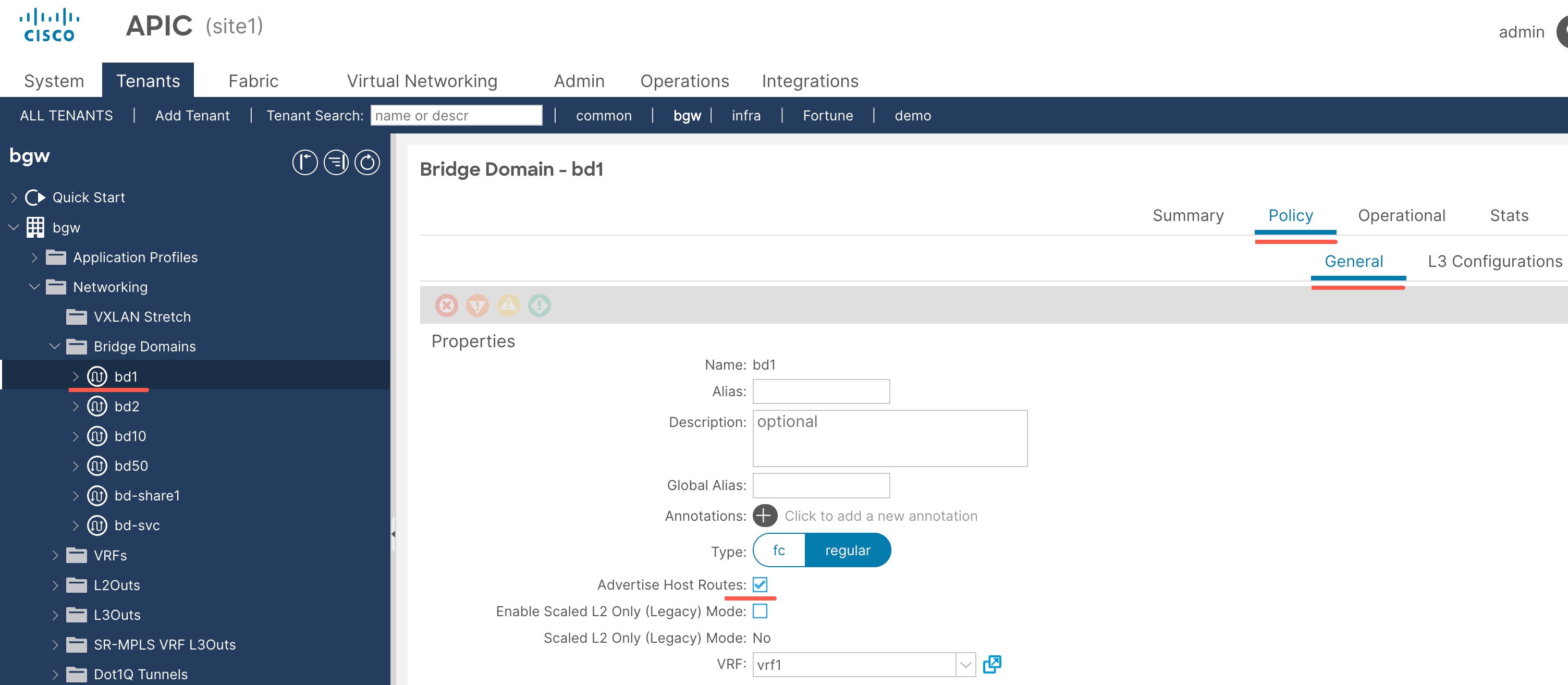
Figure 328. ACI Site 2 bd1 Advertise Host Routes
With host-based routing enabled on bd1, Core-WAN router learns /32 host routes for all active endpoints such as 192.168.1.11 in ACI Site 1 via Router 1 and 192.168.1.201 in ACI Site 2 via Router 2.
The following figures is the routing table for 192.168.1.0/24 and the hosts routes on Core-WAN.
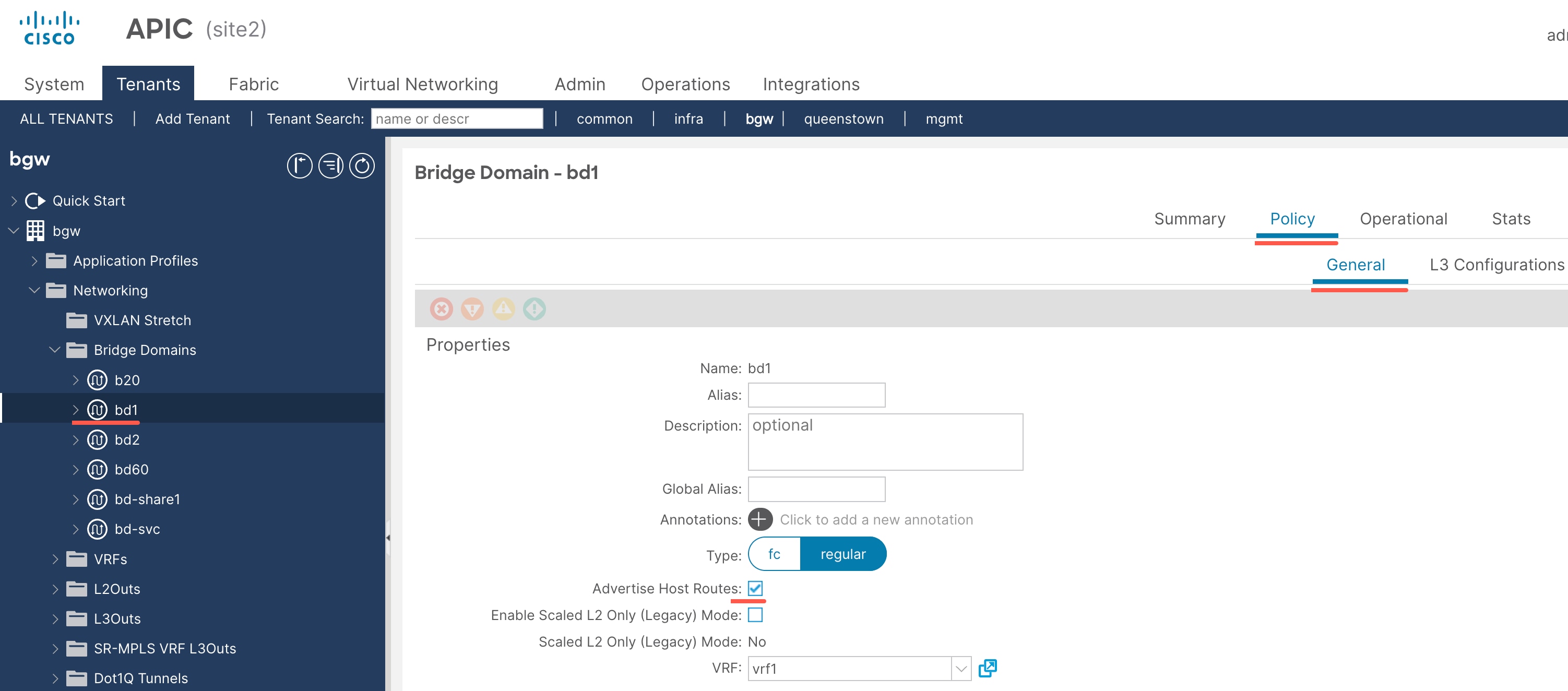
Figure 329. Core-WAN Router learns host routes
The figures below show traceroute outputs on an external endpoint 108.0.0.10, which are to 192.168.1.11 and 192.168.1.201.
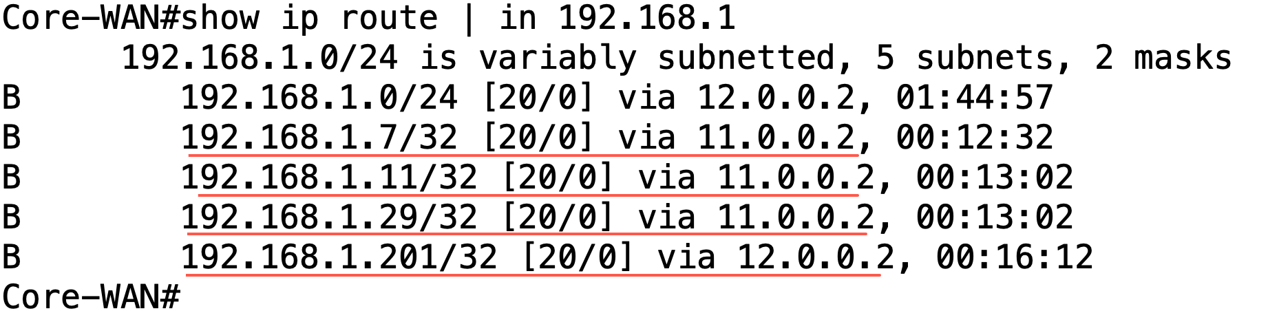
Figure 330. Core WAN external endpoint
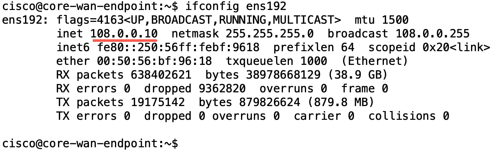
Figure 331. Traceroute from core wan external endpoint to ACI Site 1 endpoint

Figure 332. Traceroute from core wan external endpoint to ACI Site 2 endpoint
Incoming default route (0/0) consideration
This subsection discusses key considerations when an external router advertises the default route (0.0.0.0/0) to both ACI sites.
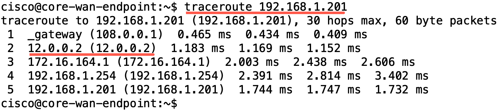
Figure 333. External router advertises default route to both ACI sites
In a typical scenario where both L3Outs are operational and without route manipulation, local L3Out is always preferred for outgoing communication. The bi-directional communication between EP-1, EP-2, and EP-3 remains uninterrupted, provided that the subnet 108.0.0.0/24 or 0.0.0.0/0 is configured as an external Subnet Selector in the ESG ext-core on both ACI sites. Although incoming traffic from EP-3 may follow a suboptimal path such as using Site 1 as a transit to reach EP-2—the data plane between EP-1, EP-2, and EP-3 functions correctly. However, if Core-WAN advertises only 0.0.0.0/0 and a specific subnet, 108.0.0.0/24, is defined as the External Subnet Selector on both ACI Sites, then if L3Out-2 goes down, communication from EP-3 to EP-2 will be disrupted. Similarly, if L3Out-1 goes down, communication from EP-3 to EP-1 will be disrupted. This behavior was previously discussed in the sub-section “Considerations for Endpoint Security Groups (ESG) with External Subnet Selectors.”
To support the failover scenario where either of the two L3Outs could go down, and the WAN device advertises only the default route (0.0.0.0/0), it is required to configure 0.0.0.0/0 as the External Subnet Selector in the ESG ext-core on both sites.
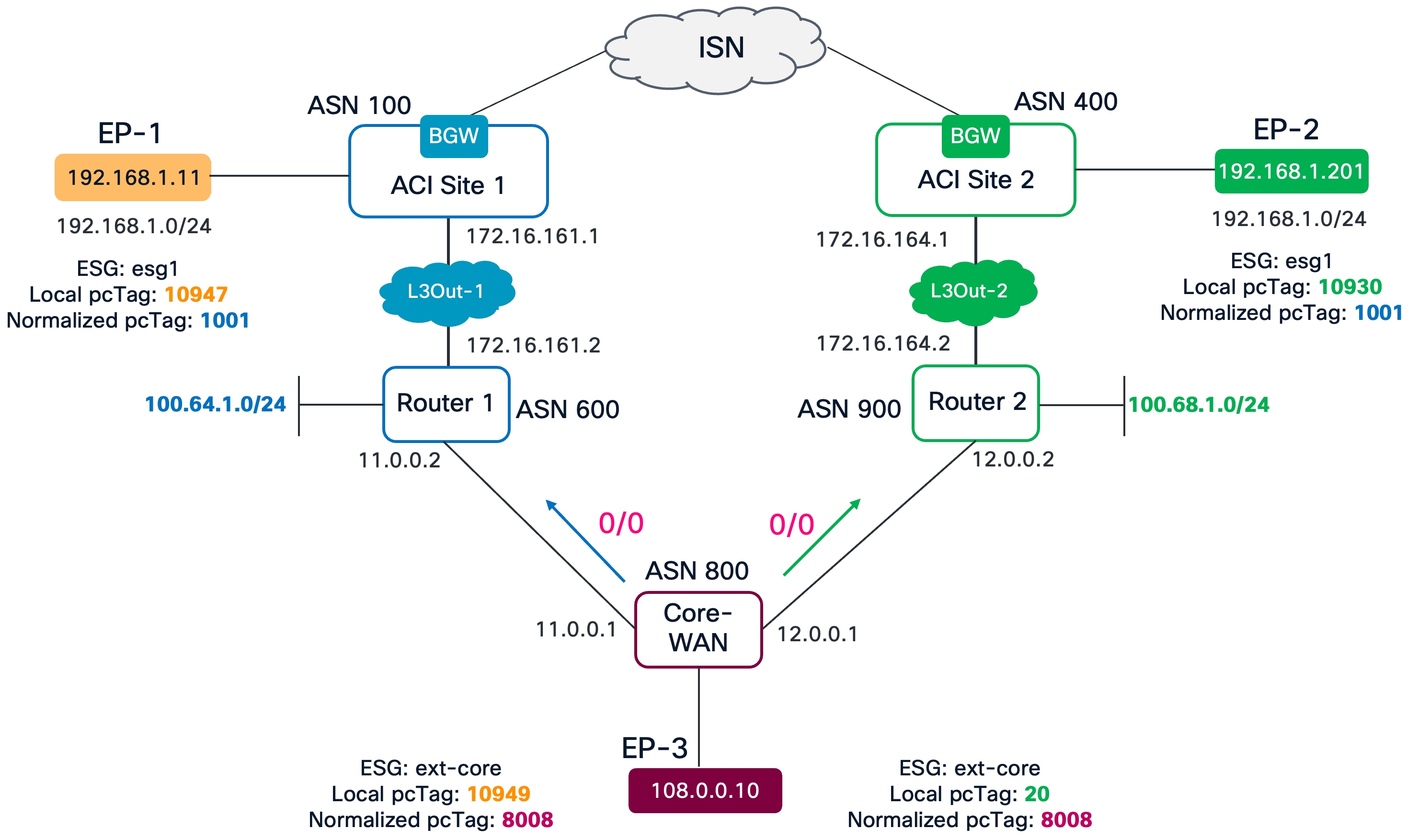
Figure 334. ACI Site 2 traffic failover when L3Out-2 down
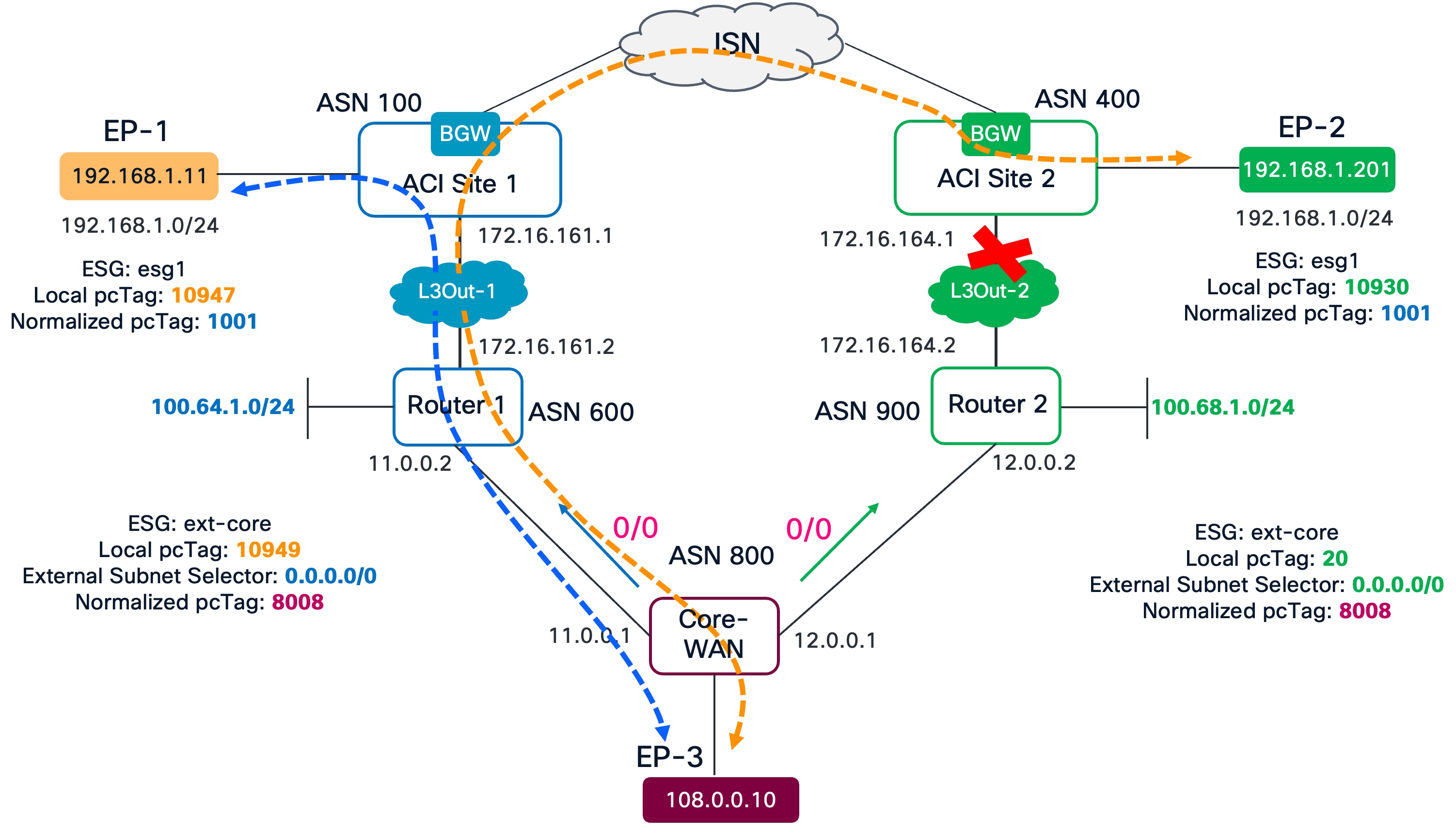
Figure 335. ACI Site 1 traffic failover when L3Out-1 down
The same consideration applies to non-default routes. For example, if the WAN device advertises only the 108.0.0.0/16 prefix, the External Subnet Selector on both sites must be configured exactly as 108.0.0.0/16.
To achieve fine granularity on the ESG ext-core by defining a non-default subnet instead of 0.0.0.0/0 for example, using 108.0.0.0/24 as the External Subnet Selector to restrict traffic only to and from 108.0.0.0/24, the WAN side must advertise the specific route, including 108.0.0.0/24, to the ACI Sites. This ensures that only the designated subnet is classified and allowed through the ESG ext-core, providing more precise traffic control.
Cross-site data plane connectivity may be disrupted if an existing Endpoint Security Group (ESG) uses an External Subnet Selector configured as a supernet or default route (0.0.0.0/0). For example, if an existing ESG has 108.0.0.0/16 as its External Subnet Selector, defining a new ESG with an overlapping selector such as 108.0.0.0/24 could cause data plane failures. In summary, ensure that ESGs use non-overlapping External Subnet Selectors that correspond to the prefixes received from the local L3Out.
Use Case 9: Inter-VRF Communication (Shared Services) with Stretched BDs
This section covers an inter-VRF communication use case, also called shared service, where the source and the destination reside in different VRFs.
The figure below illustrates an example used in the section. Although this example shows stretched VRFs, Bridge Domains, and ESGs, only the VRF must be stretched. The BD and ESG may remain local to each site. A contract is configured between ESG esg1 in VRF1 and ESG share1 in VRF Share.
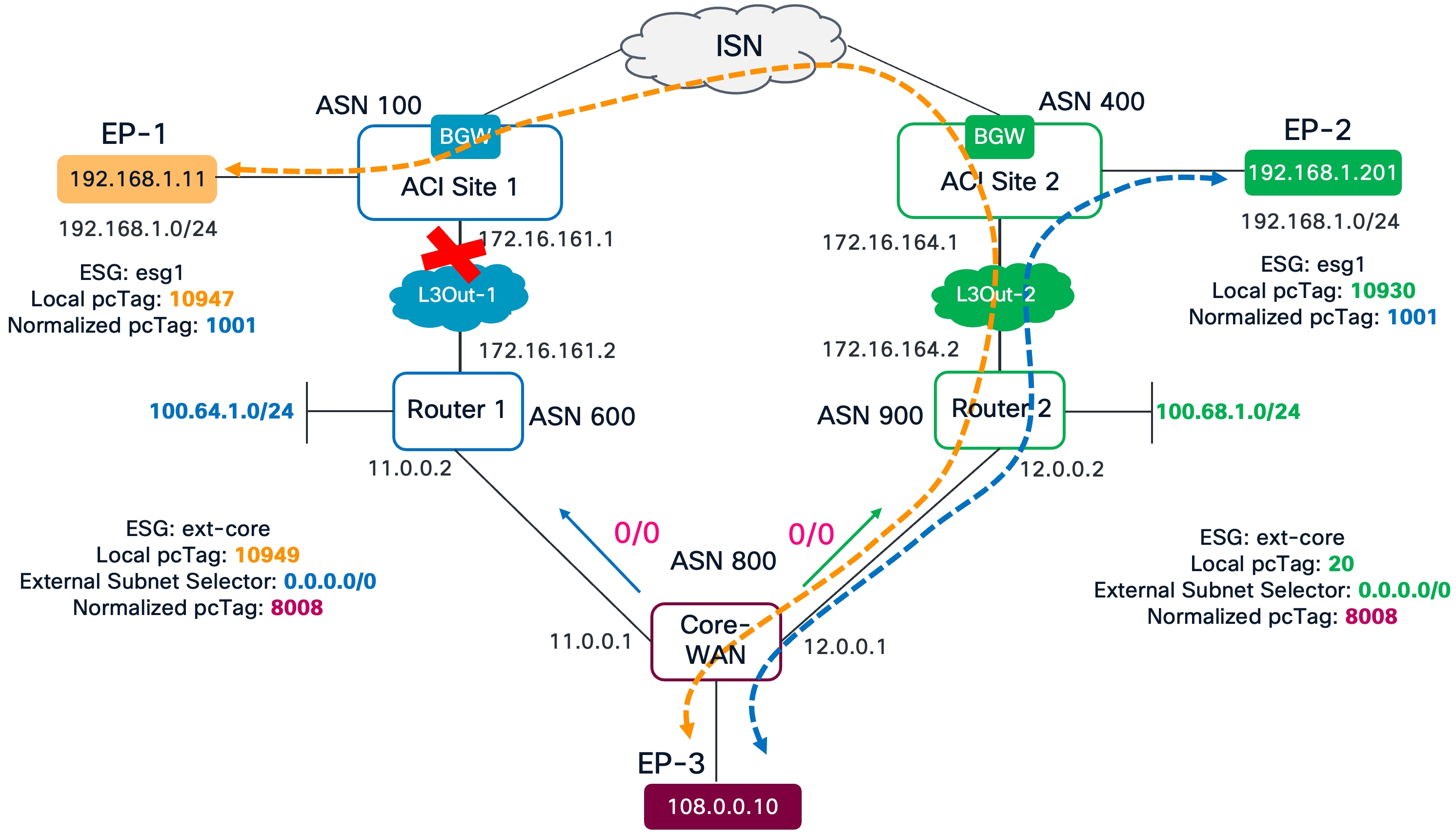
Figure 336. Shared Service use case
The assumption is that the VRF vrf1, BD bd1, and ESG esg1 were already created in the previous sub-section User Tenant Baseline Configuration and Use Case 1: Intra-Subnet Communication.
On both sites, the required configuration steps are following:
1. Create the VRF named “share” and stretch it by deploying it on the Border Gateway, ensuring the same normalized VNI is set (60001 in this example).
2. Create the BD bd-share1 in VRF share with subnet 172.16.31.254/24 and stretch it by deploying it on Border Gateway, ensuring the same normalized VNI is set (31000 in this example).
3. Create the EPG share1 mapped to BD bd-share1, associate it to domain.
4. Create the ESG share1 ensuring the same normalized pcTag is set (2001 in this example), use EPG share1 as selector.
5. Configure route leak between VRF vrf1 and VRF share, make sure the leaked subnet cover /32 host routes:
◦ leak Internal Prefix 192.168.1.0/24 with less than or equal (prefix) of 32 from VRF vrf1 to VRF share
◦ leak Internal Prefix 172.16.31.0/24 with less than or equal (prefix) of 32 from VRF share to VRF vrf1
6. Apply a tenant-scope contract between ESG esg1 and ESG share1.
Please note that the steps above are not necessarily in a fixed order. Steps 2, 3, and 4 can be performed in any sequence.
Create Provider VRF and Bridge Domain
The figures below are VRF and BD configurations in ACI Site 1.
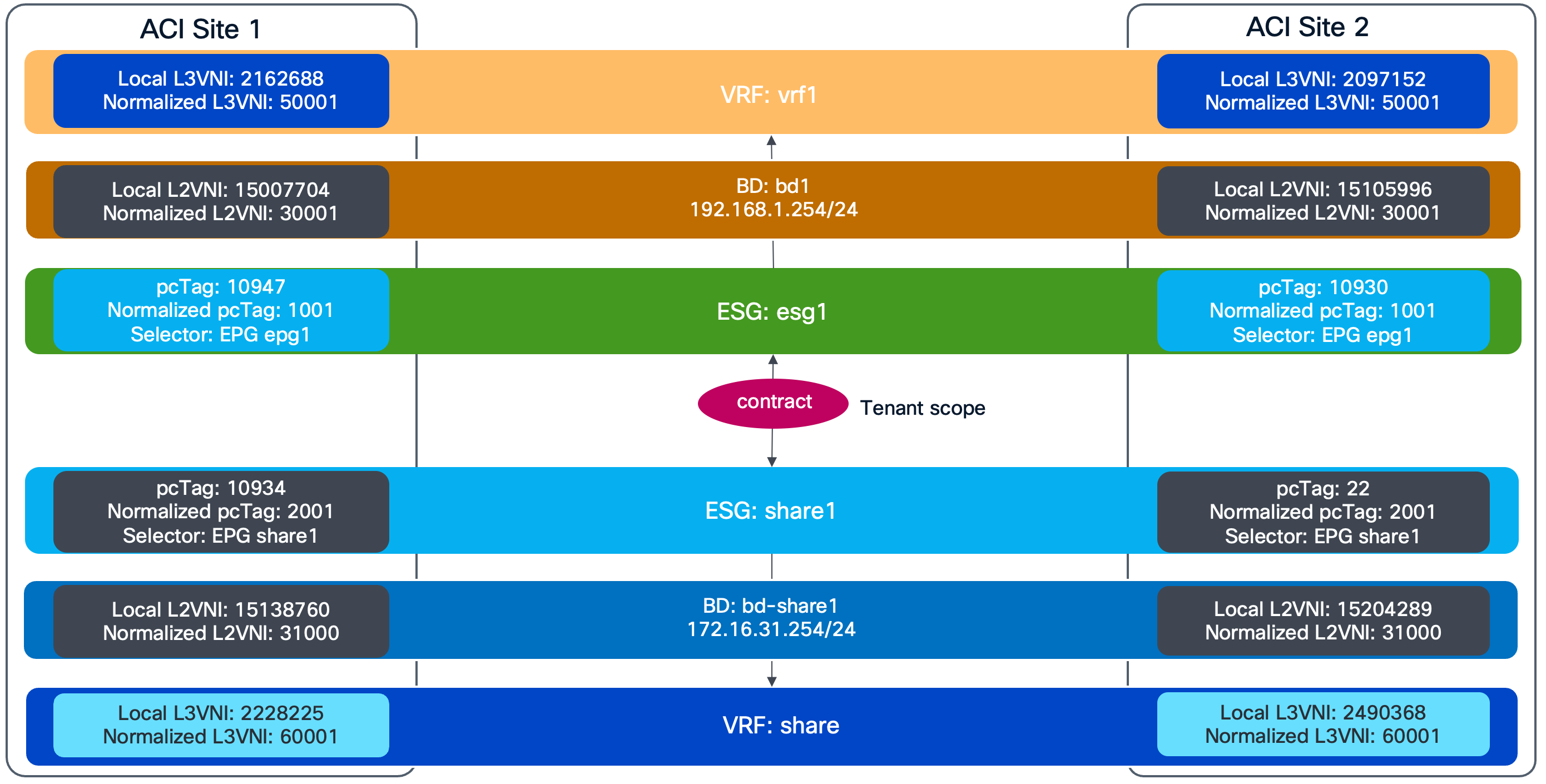
Figure 337. ACI Site 1 VRF share
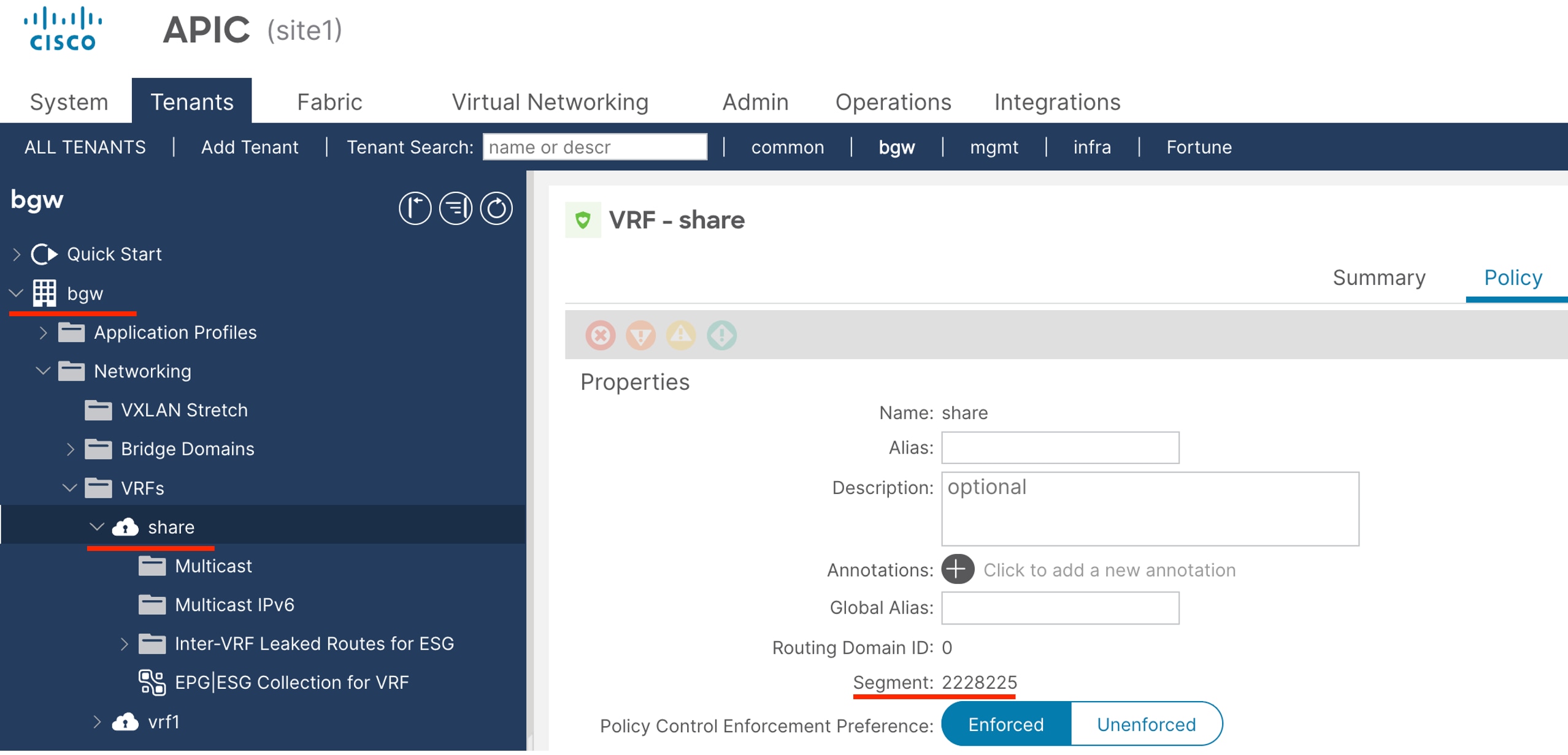
Figure 338. ACI Site 1 BD bd-share1
The figures below are normalized VNIs configuration in ACI Site 1.
● VRF share: normalized VNI 60001
● BD bd-share1: normalized VNI 31000
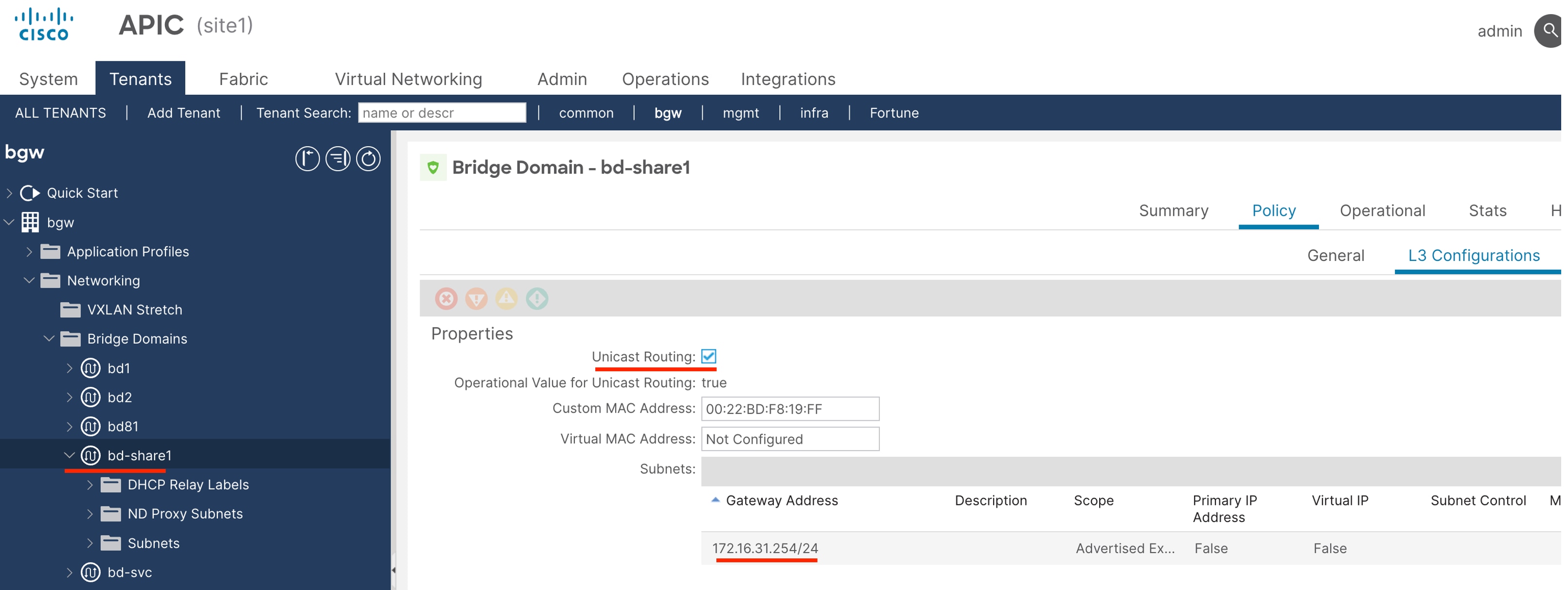
Figure 339. ACI Site 1 stretched VRF share
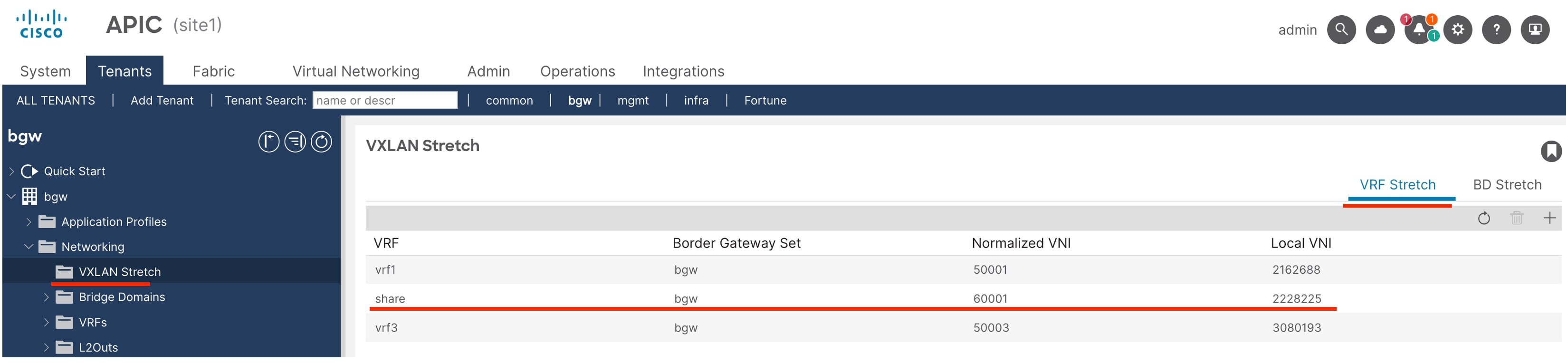
Figure 340. ACI Site 1 stretched BD bd-share1
The figures below are VRF and BD configurations in ACI Site 2.
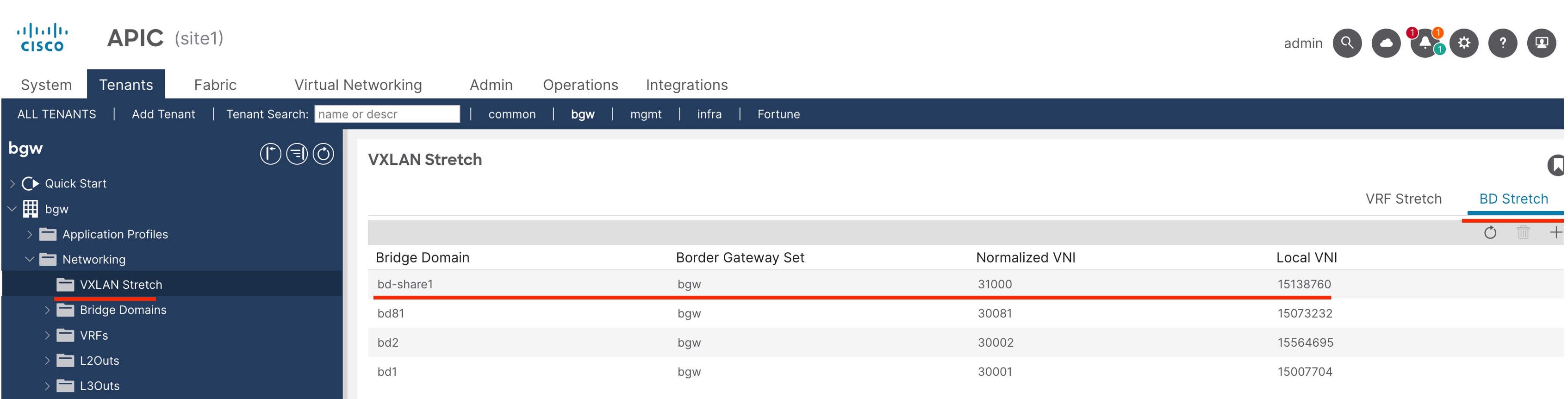
Figure 341. ACI Site 2 VRF share
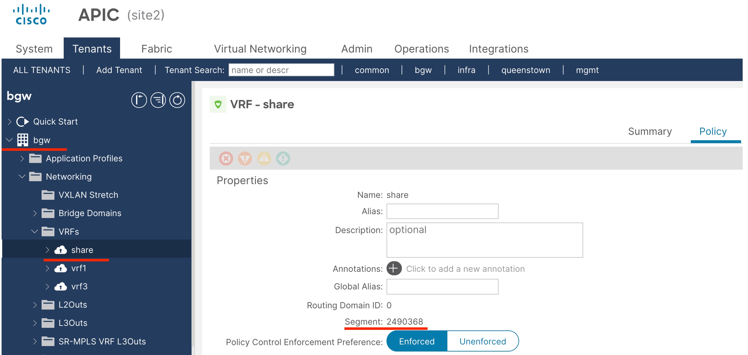
Figure 342. ACI Site 2 BD bd-share1
The figures below are normalized VNIs configuration in ACI Site 2.
● VRF share: normalized VNI 60001
● BD bd-share1: normalized VNI 31000
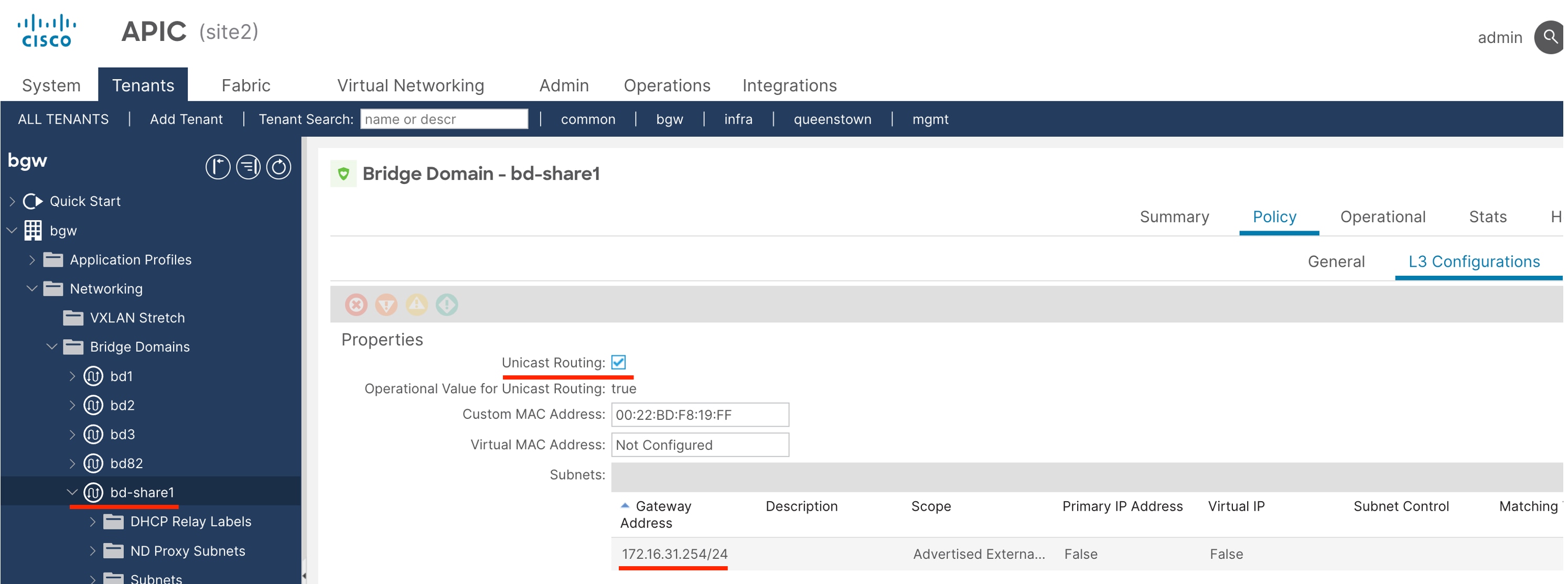
Figure 343. ACI Site 2 stretched VRF share
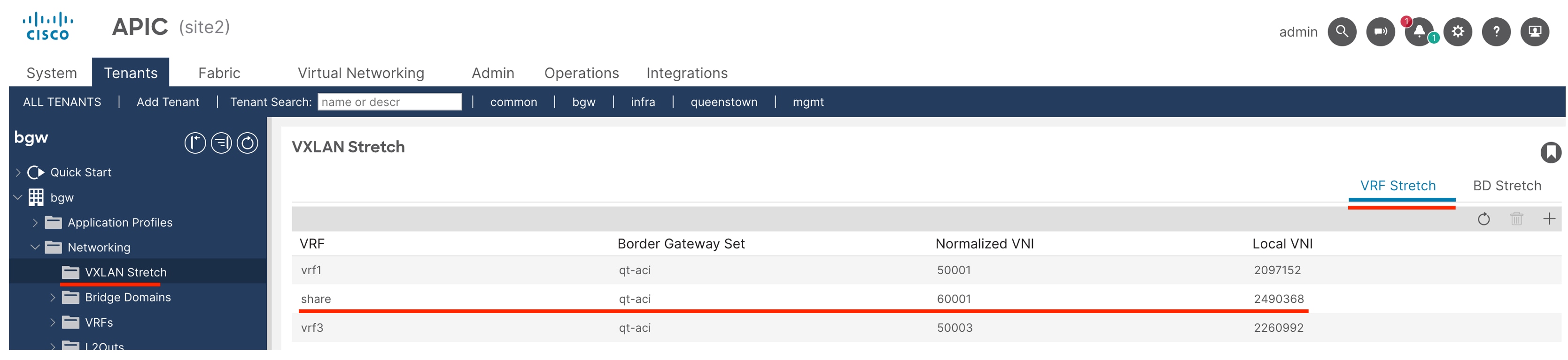
Figure 344. ACI Site 2 stretched BD bd-share1
The figures below are ESG share1 configurations in ACI Site 1.
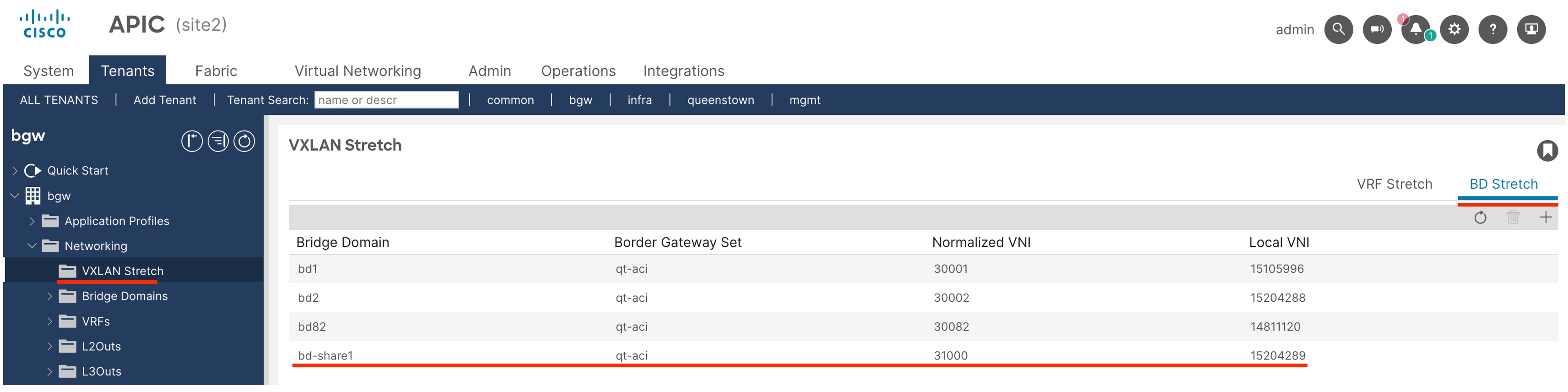
Figure 345. ACI Site 1 ESG share1
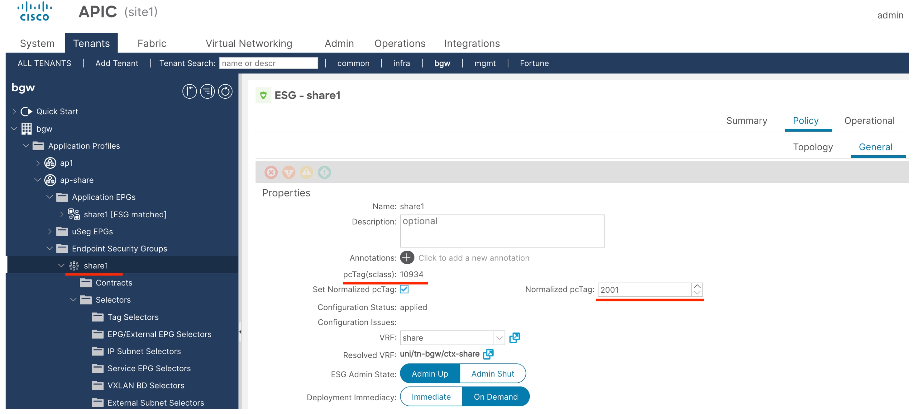
Figure 346. ACI Site 1 ESG share1 EPG Selector
The figures below are ESG share1 configurations in ACI Site 2.
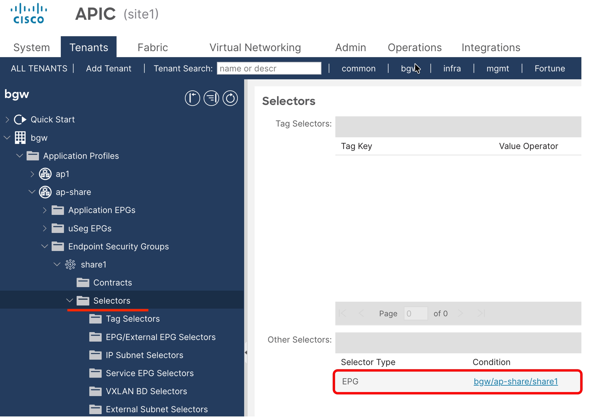
Figure 347. ACI Site 2 ESG share1
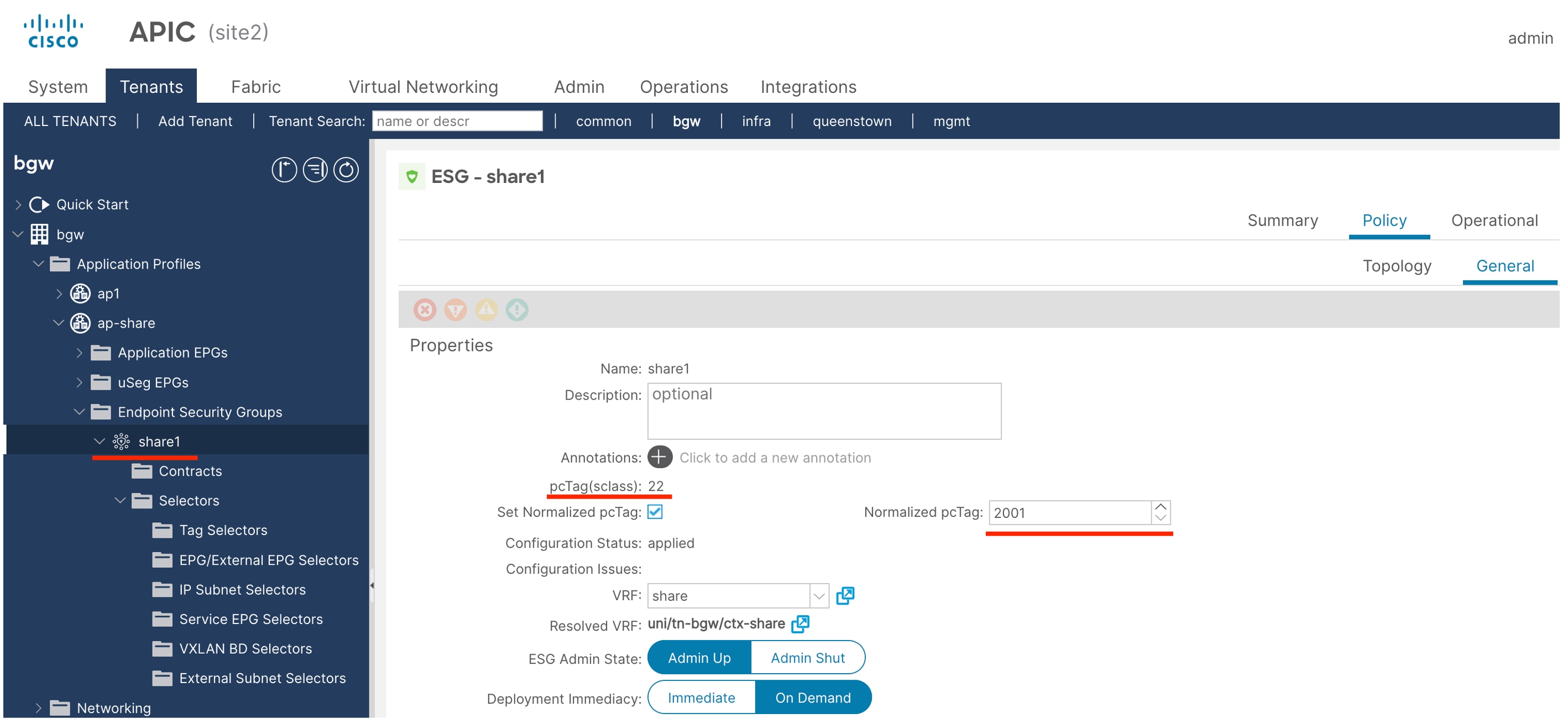
Figure 348. ACI Site 2 ESG share1 EPG Selector
Create and Apply Tenant Scope Contract
The figures below are contract configurations in ACI Site 1. Note that the contract scope is set to “Tenant” instead of “VRF” because it is for inter-VRF communication for ESGs in the same tenant.
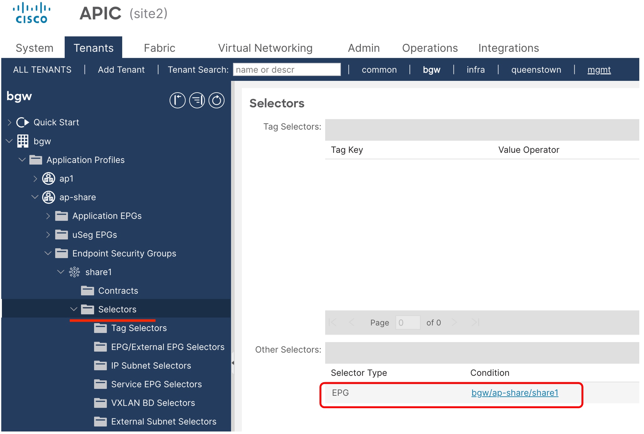
Figure 349. ACI Site 1 tenant scope contract
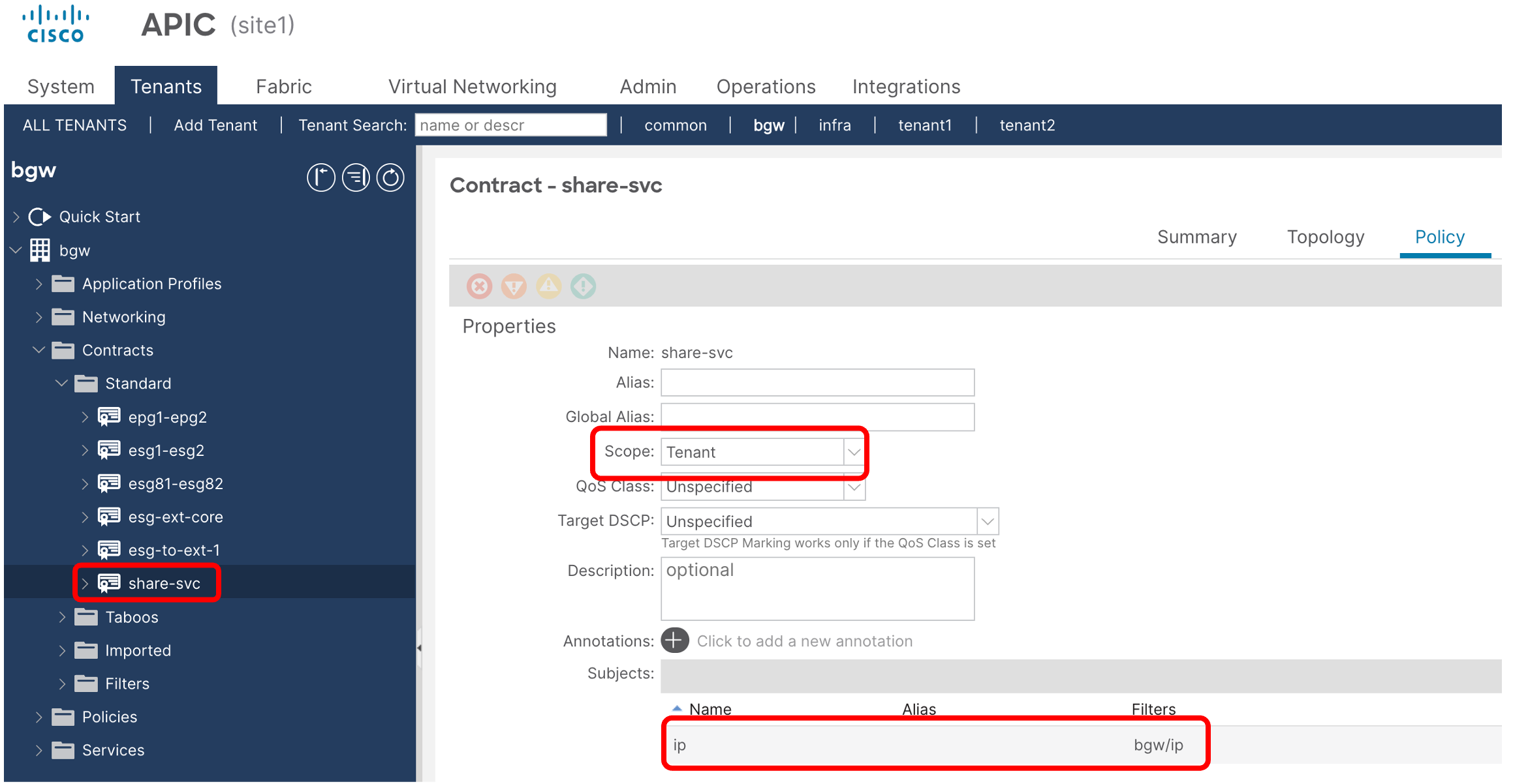
Figure 350. ACI Site 1 ESG esg1 contract consumer
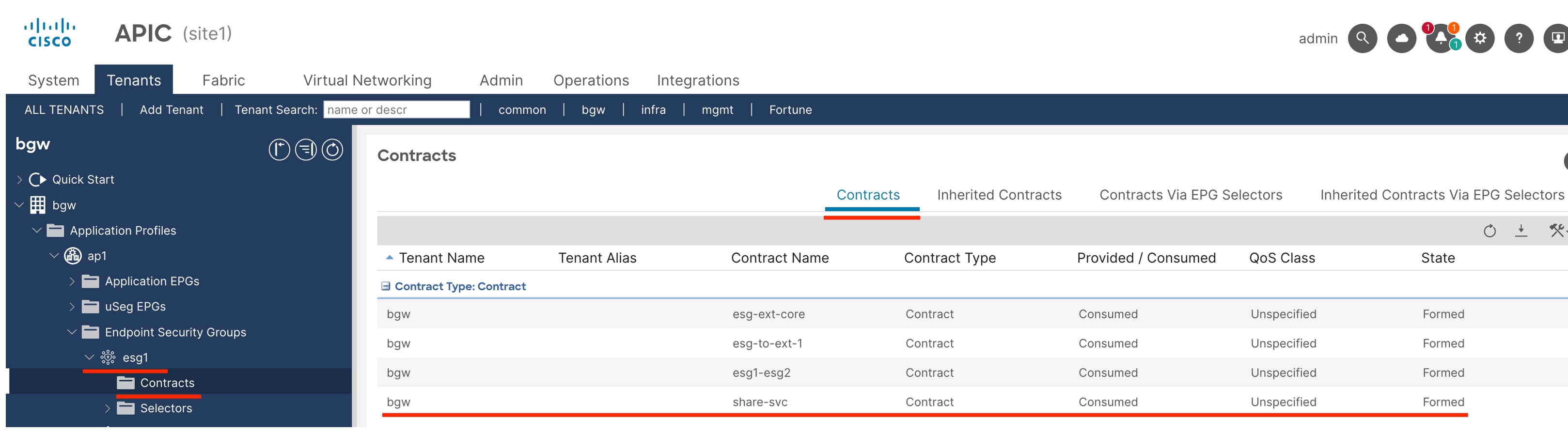
Figure 351. ACI Site 1 ESG share1 contract provider
The figures below are contract configurations in ACI Site 2.
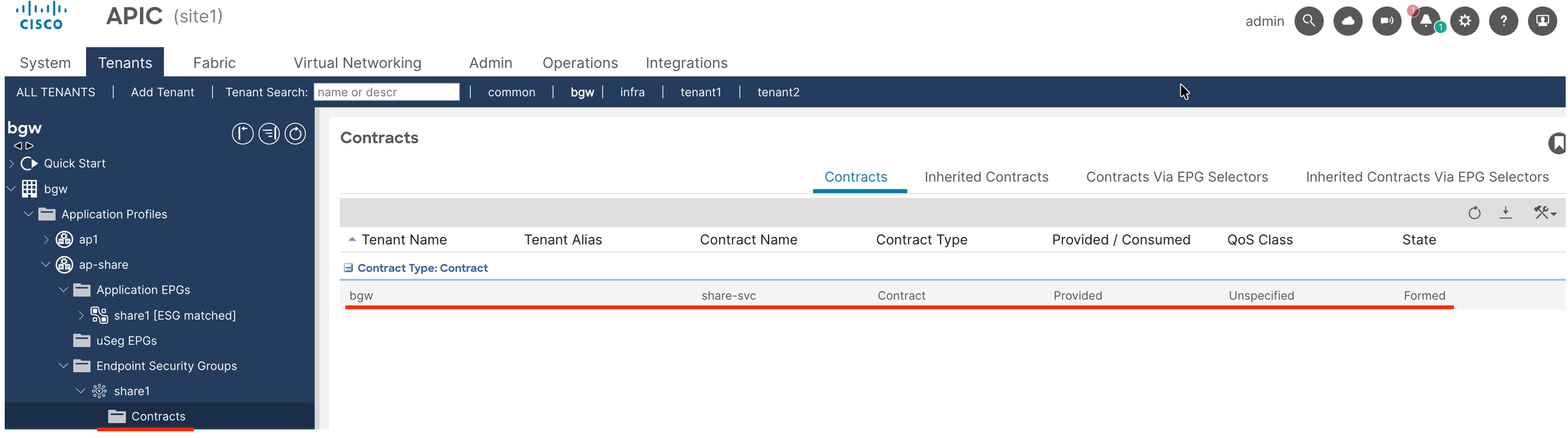
Figure 352. ACI Site 2 tenant scope contract
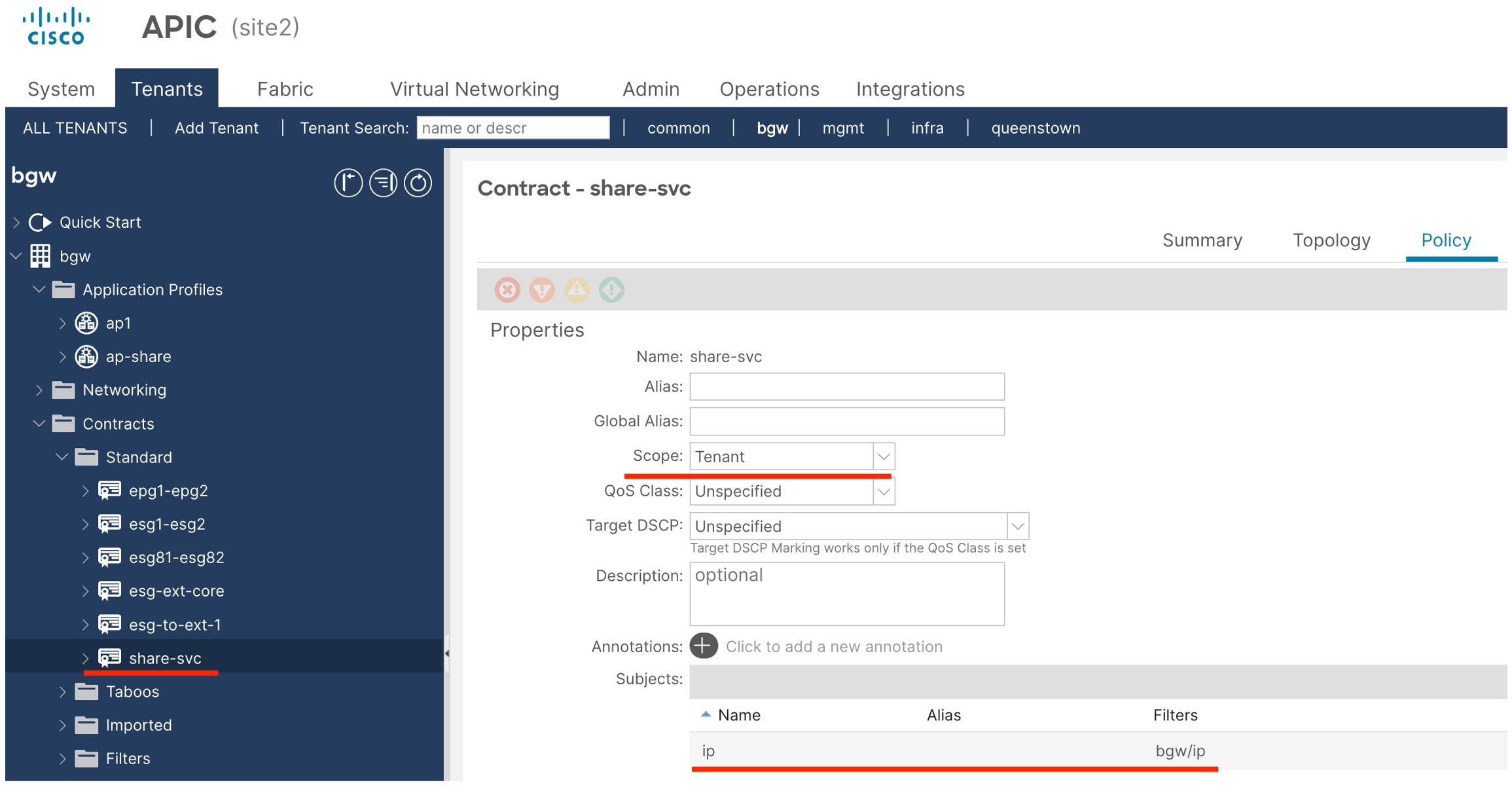
Figure 353. ACI Site 2 ESG esg1 contract consumer
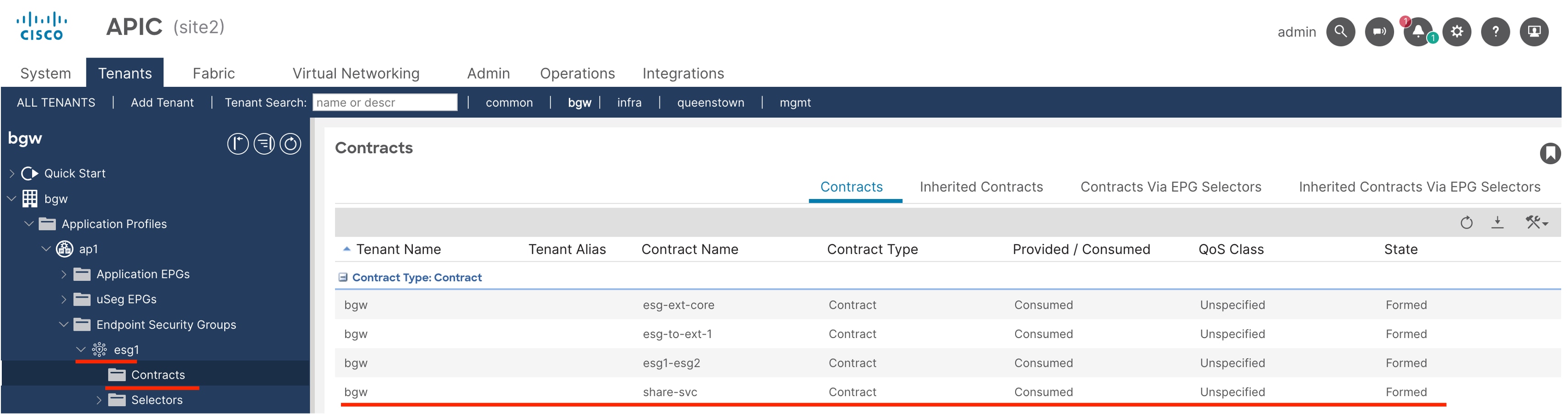
Figure 354. ACI Site 2 ESG share1 contract provider
Although the tenant-scope contract between ESGs was created in the previous step to define the security policies allowing communication, this contract alone does not establish network connectivity between the endpoints. Because the endpoints reside in different VRFs, route leaking must be configured to enable routing reachability between these VRFs. Without this route leaking configuration, the endpoints cannot communicate despite the contract being in place.
The next step is to configure route leak between VRF vrf1 and VRF share. The configuration steps are identical on both ACI Sites.
In ACI Site 1, navigate to VRFs -> vrf1 -> Inter-VRF Leaked Routes for ESG -> Internal Prefixes. From the toolbox dropdown list, choose “Create Leaked Internal Prefix”.
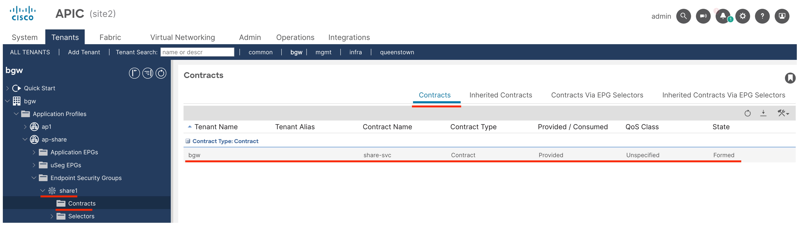
Figure 355. ACI Site 1 Create Leaked Internal Prefix from VRF vrf1 to VRF share
Configure 192.168.1.0/24 in IP field. Although bd1 subnet is 192.168.1.254/24, to include the /32 host routes (so that host routes for endpoints in vrf1 are leaked to the other VRF), “Less Than or Equal (Prefix)” needs to be set to 32. (In the case of IPv6 host routes, it needs to be set to 128.)
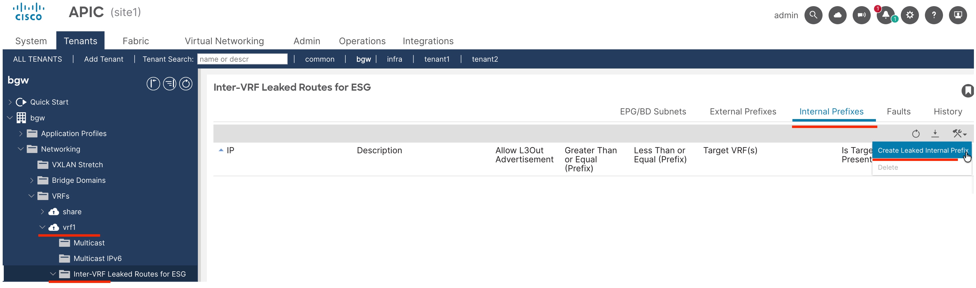
Figure 356. Create Leaked Internal Prefix 192.168.1.0/24
Click “+” to add the destination VRF (which is VRF share in this example).
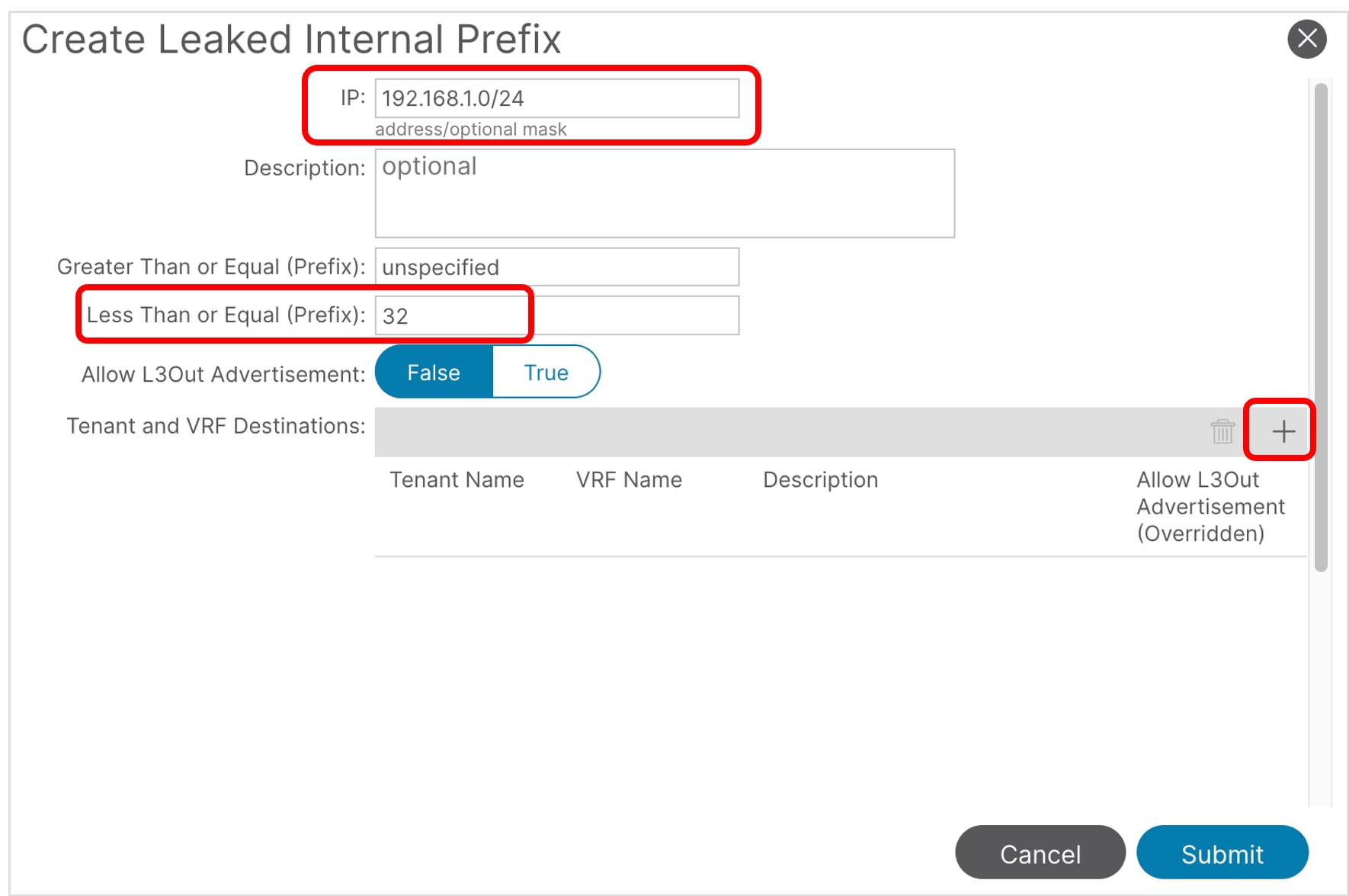
Figure 357. ACI Site 1 choose share as the destination VRF
Click Submit to finish Inter-VRF route leak configuration for the route from VRF vrf1 to VRF share.
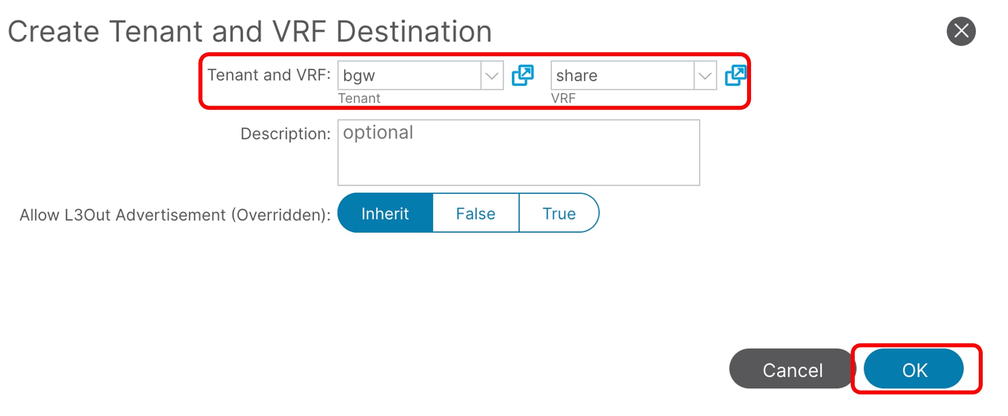
Figure 358. ACI Site 1 route leak from VRF vrf1 to VRF share completion
For the other direction, which is from VRF share to VRF vrf1, navigate to VRFs -> share -> Inter-VRF Leaked Routes for ESG -> Internal Prefixes. From the toolbox dropdown list, choose “Create Leaked Internal Prefix”.
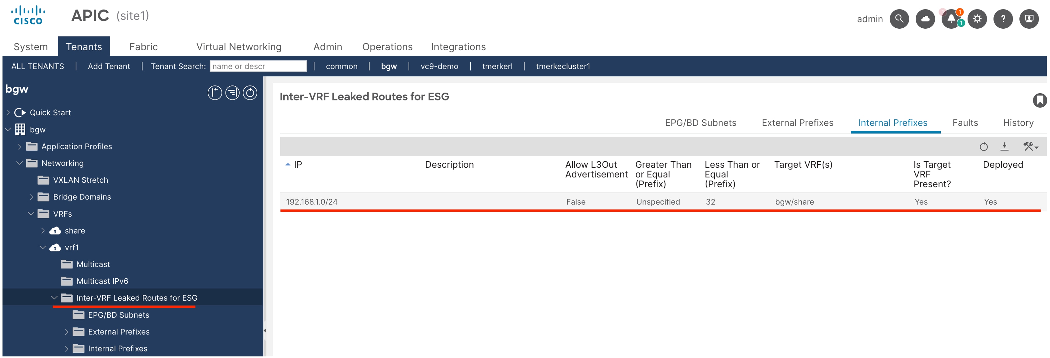
Figure 359. ACI Site 1 Create Leaked Internal Prefix from VRF share to VRF vrf1
Configure 172.16.31.0/24 in IP field. Although bd-share1 subnet is 172.16.31.254/24, to include the /32 host routes (so that host routes for endpoints in VRF share are leaked to the other VRF), “Less Than or Equal (Prefix)” needs to be set to 32. (In the case of IPv6 host routes, it needs to be set to 128).
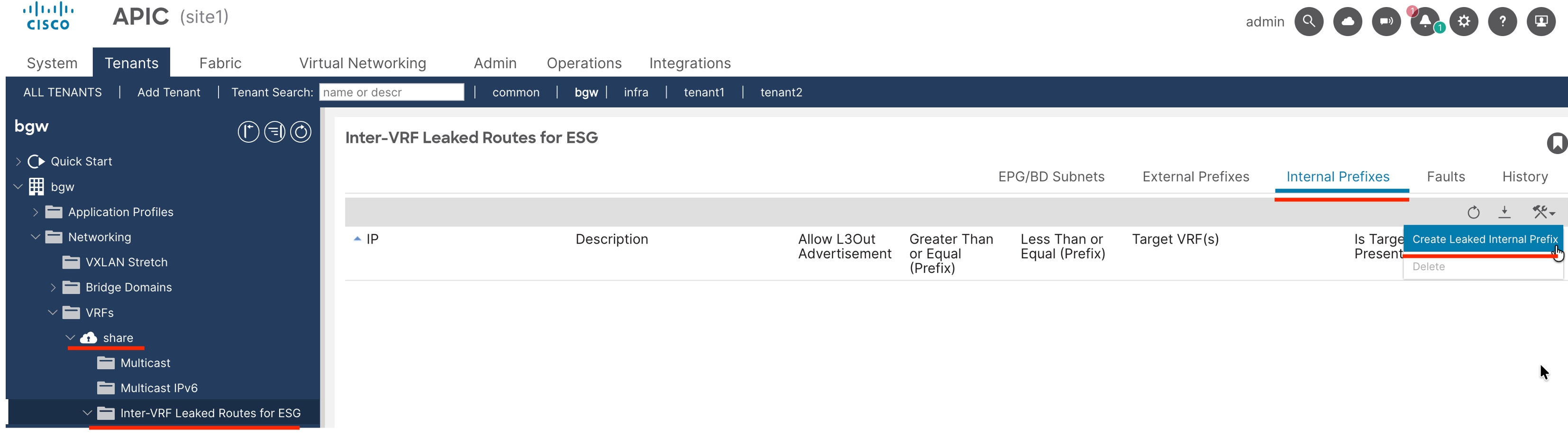
Figure 360. Create Leaked Internal Prefix 172.16.31.0/24
Click “+” to add the destination VRF (which is VRF vrf1 in this example).
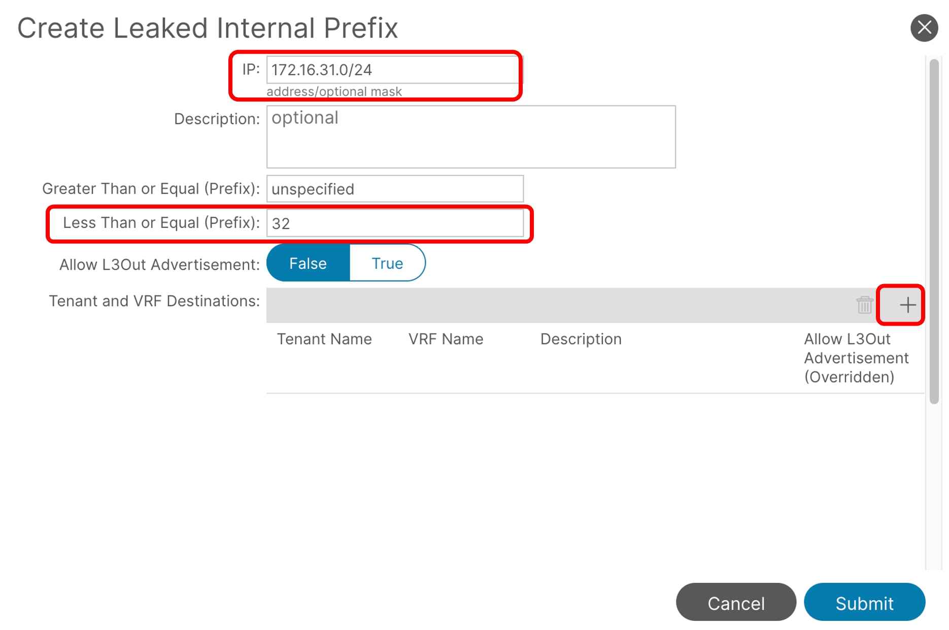
Figure 361. ACI Site 1 choose vrf1 as destination VRF
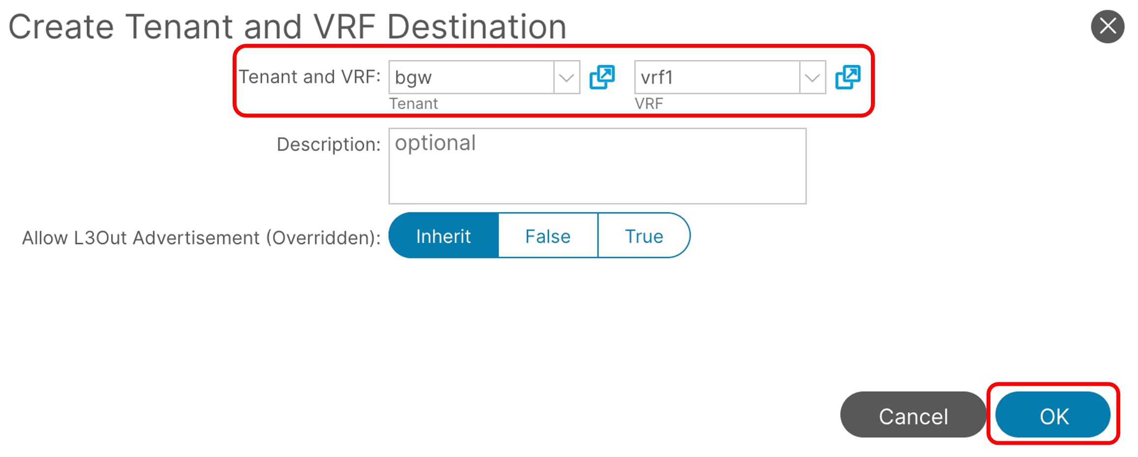
Figure 362. ACI Site 1 Route Leak from VRF share to VRF vrf1 completion
The procedure to configure route leaking is identical in ACI Site 2. The figures below are examples.
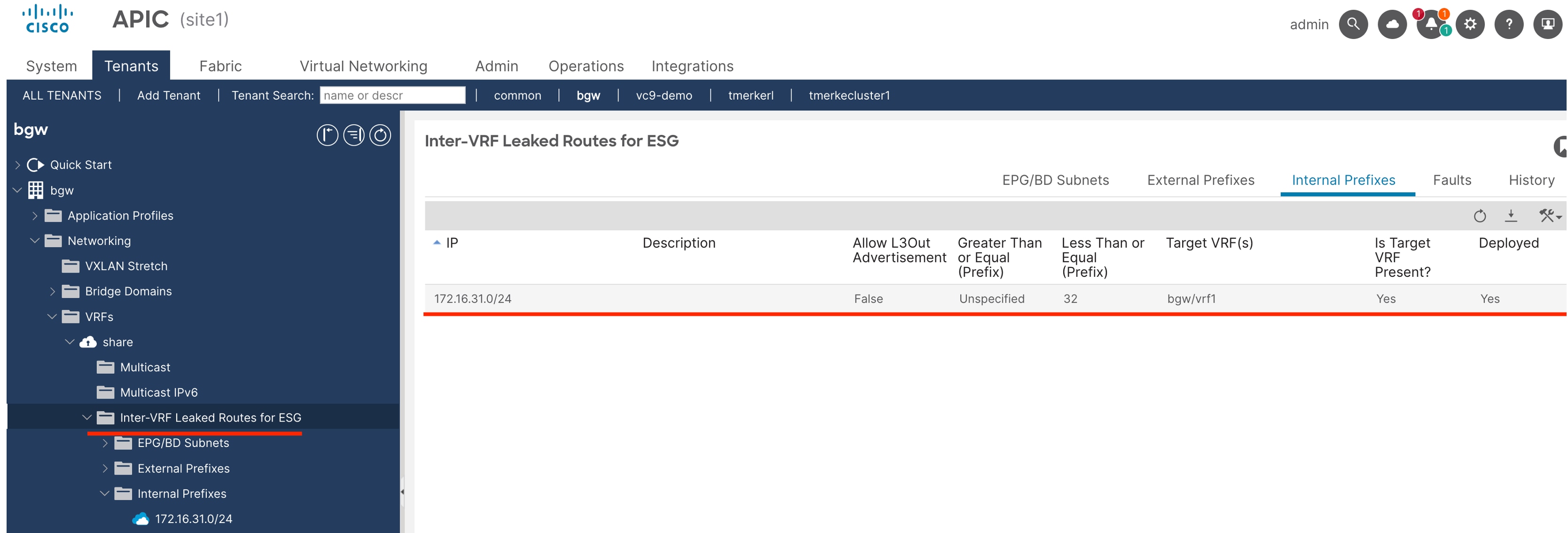
Figure 363. ACI Site 2 Route Leak from VRF vrf1 to VRF share completion
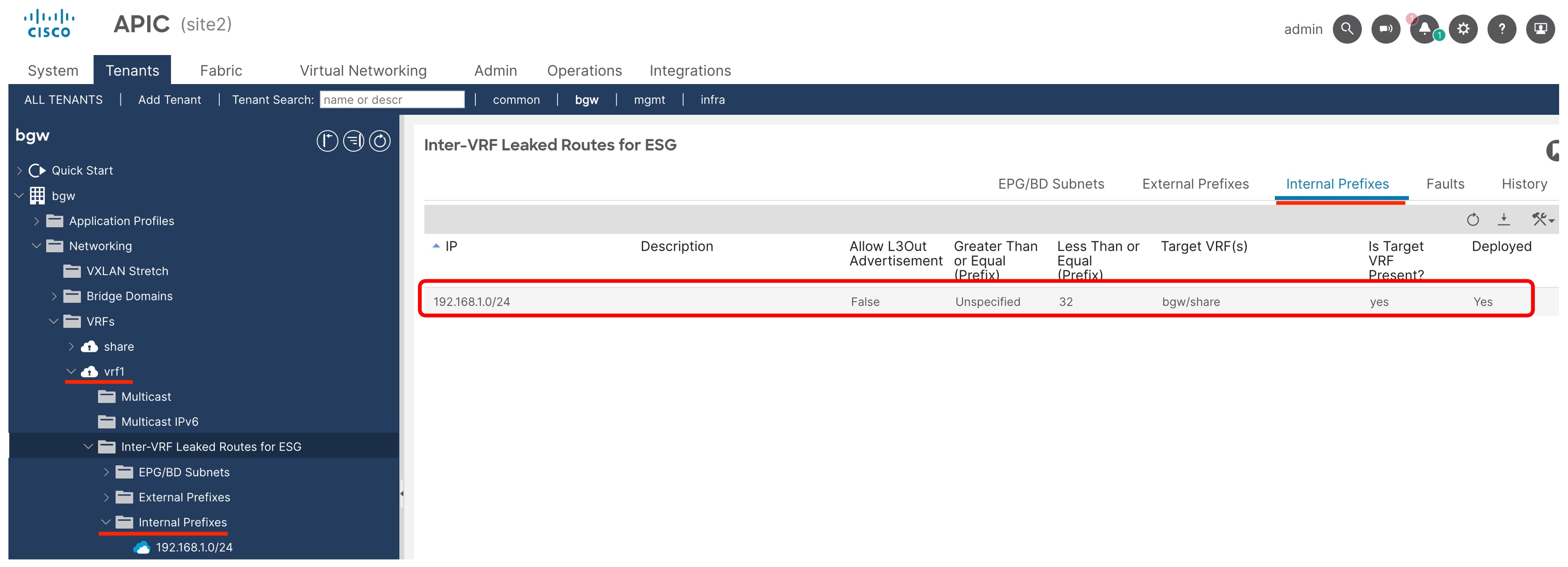
Figure 364. ACI Site 2 Route Leak from VRF share to VRF vrf1 completion
Control Plane Verification
The following figure illustrates IP subnets used in this verification section.
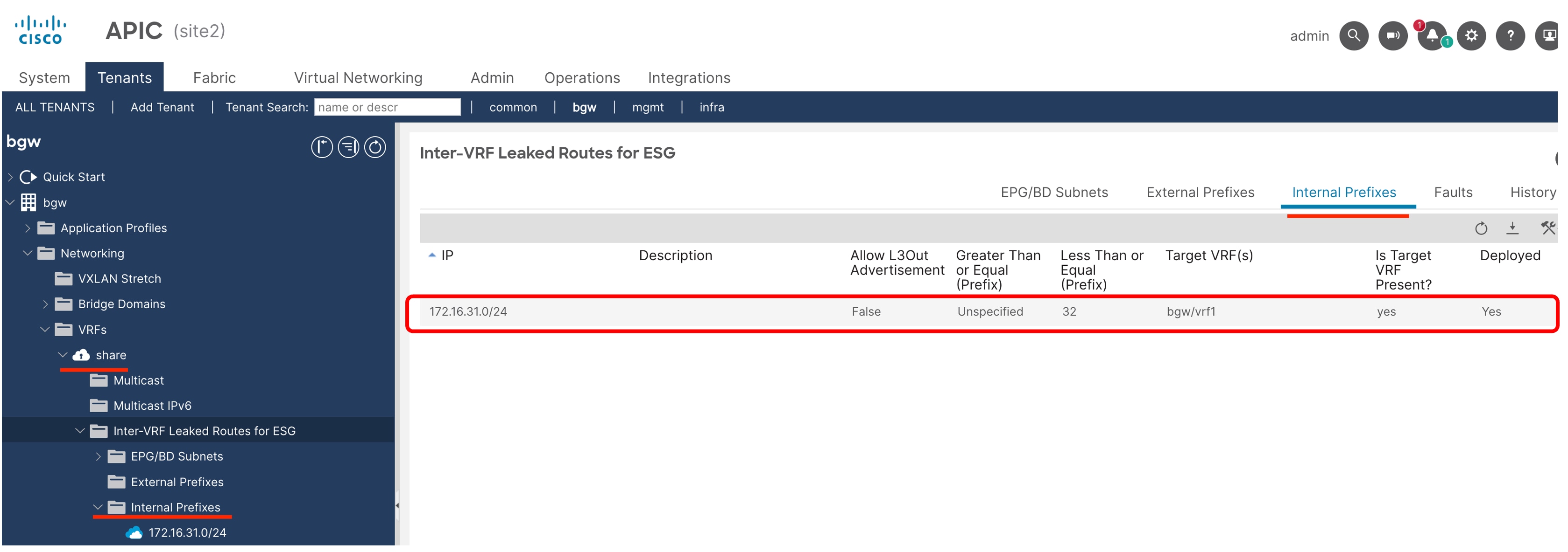
Figure 365. Route Leak diagram
Each VRF learns the route from the other VRF.
For example, the following figures are routing table information on a compute leaf in ACI Site 1.
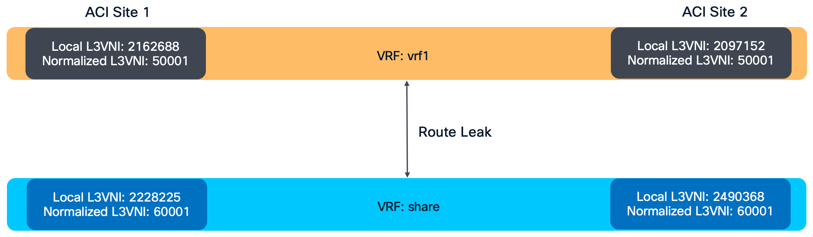
Figure 366. ACI Site 1 Compute Leaf VRF vrf1 Route Table
VRF share learns 192.168.1.0/24 from VRF vrf1. The VNI is 2162688, that is the VNI of VRF vrf1.
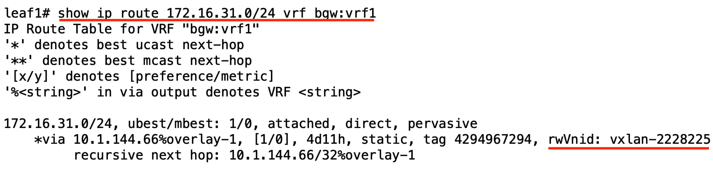
Figure 367. ACI Site 1 Compute Leaf VRF share Route Table
The following figures are routing table information on a Border Gateway in ACI Site 1. VRF vrf1 learns 172.16.31.0/24 from VRF share. The VNI is 2228225, that is the VNI of VRF share.
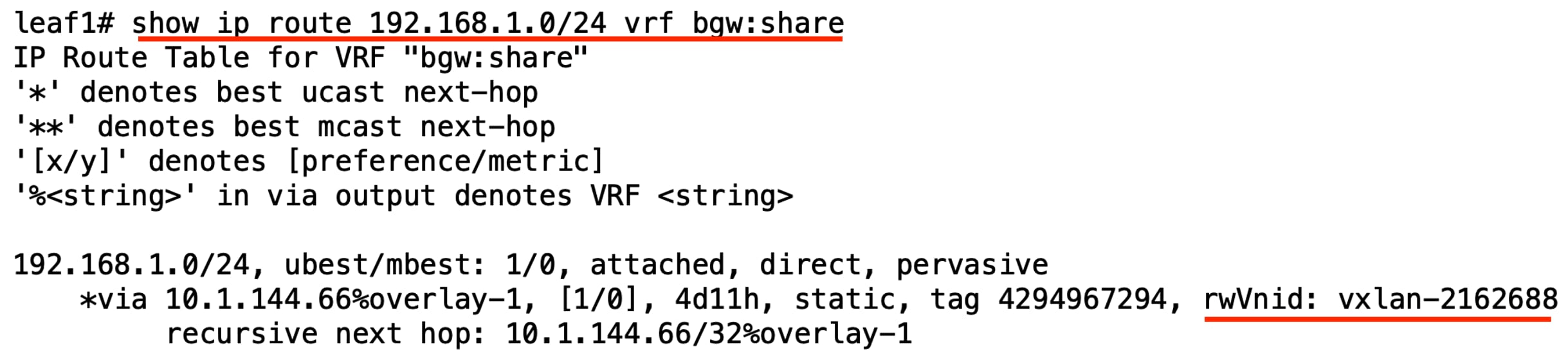
Figure 368. ACI Site 1 Border Gateway VRF vrf1 Route Table
VRF share learns 192.168.1.0/24 from VRF vrf1. The VNI is 2162688, that is the VNI of VRF vrf1.
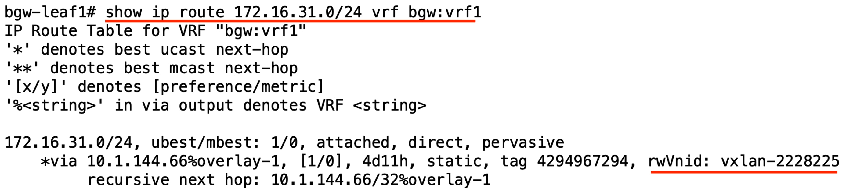
Figure 369. ACI Site 1 Border Gateway VRF share Route Table
From endpoint learning perspective, Border Gateways in ACI Site 1 learn remote endpoints (endpoints in ACI Site 2) which reside in different VRF. For example, 172.16.31.201 that is in VRF share in ACI Site 2 is learned in VRF vrf1 too.
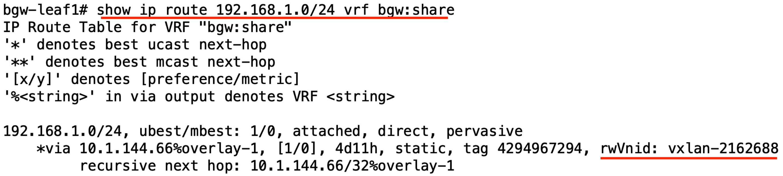
Figure 370. ACI Site 1 Border Gateway learns remote endpoint across VRF
Similarly, the endpoint 192.168.1.201, which is in VRF vrf1 at ACI Site 2, is also learned in the VRF share at ACI Site 1.
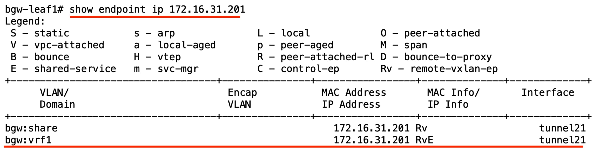
Figure 371. ACI Site 1 Border Gateway learns remote endpoint across VRF
The following figures are routing table information on a compute leaf in ACI Site 2. The results are similar information to the one in ACI Site 1. VRF vrf1 learns 172.16.31.0/24 from VRF share.
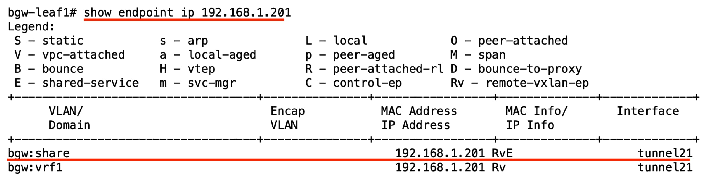
Figure 372. ACI Site 2 Compute Leaf VRF vrf1 Route Table
VRF share learns 192.168.1.0/24 from VRF vrf1.
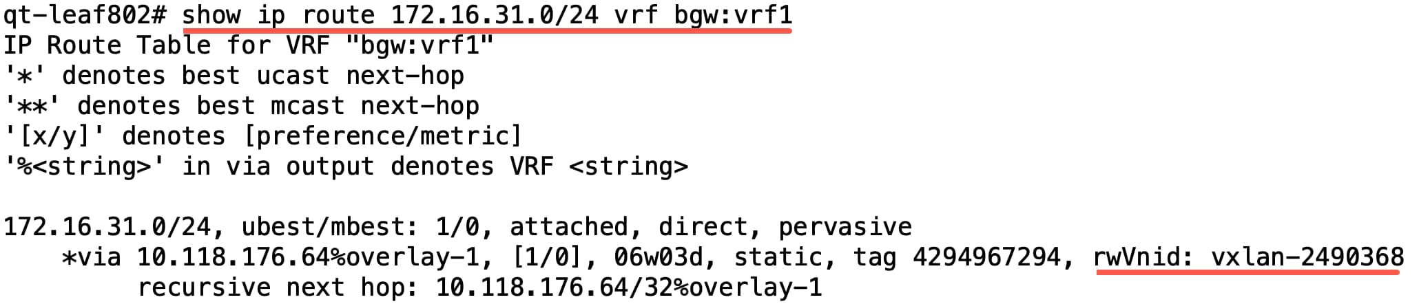
Figure 373. ACI Site 2 Compute Leaf VRF share Route Table
The following figures are routing table information on a Border Gateway in ACI Site 2. VRF vrf1 learns 172.16.31.0/24 from VRF share.
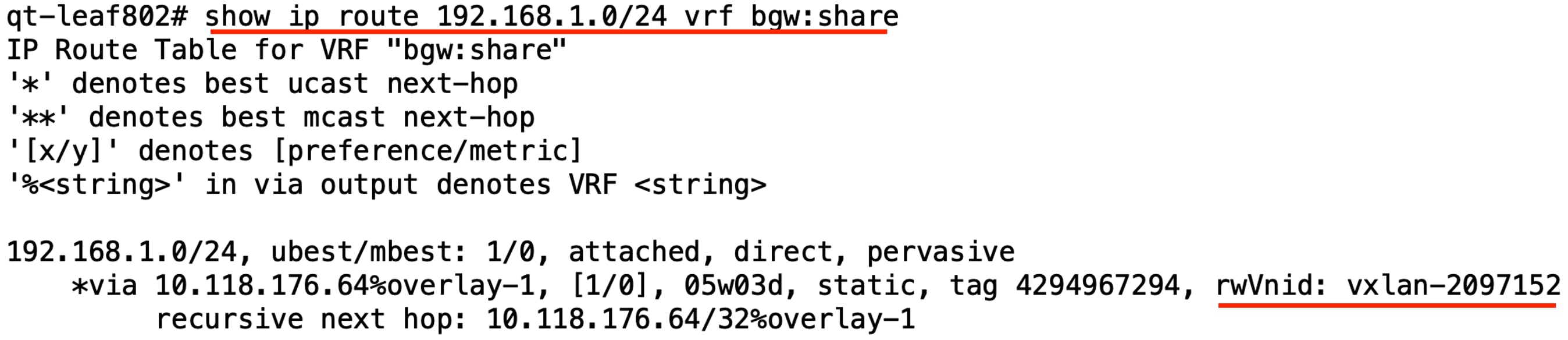
Figure 374. ACI Site 2 Border Gateway VRF vrf1 Route Table
VRF share learns 192.168.1.0/24 from VRF vrf1.
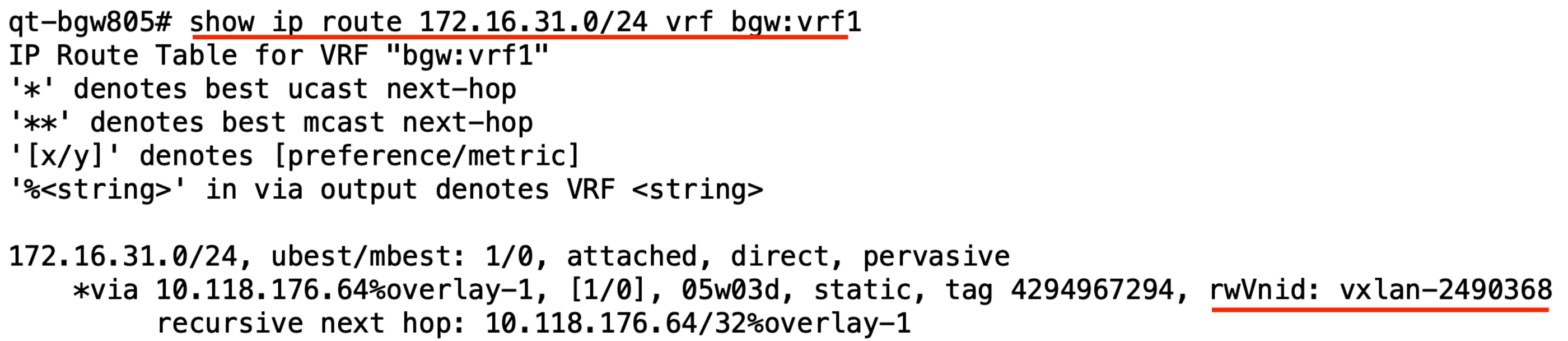
Figure 375. ACI Site 2 Border Gateway VRF share Route Table
Border Gateways in ACI Site 2 learn remote endpoints (endpoints in ACI Site 1) which reside in different VRF. For example, the endpoint 172.16.31.11, which is in VRF share at ACI Site 1, is also learned in the VRF vrf1 at ACI Site 2.
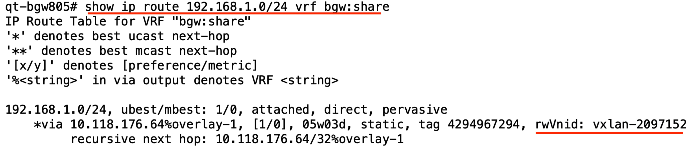
Figure 376. ACI Site 2 Border Gateway learns remote endpoint across VRF
Similar to this, the endpoint 192.168.1.11, which is in VRF vrf1 at ACI Site 1, is also learned in the VRF share at ACI Site 2.
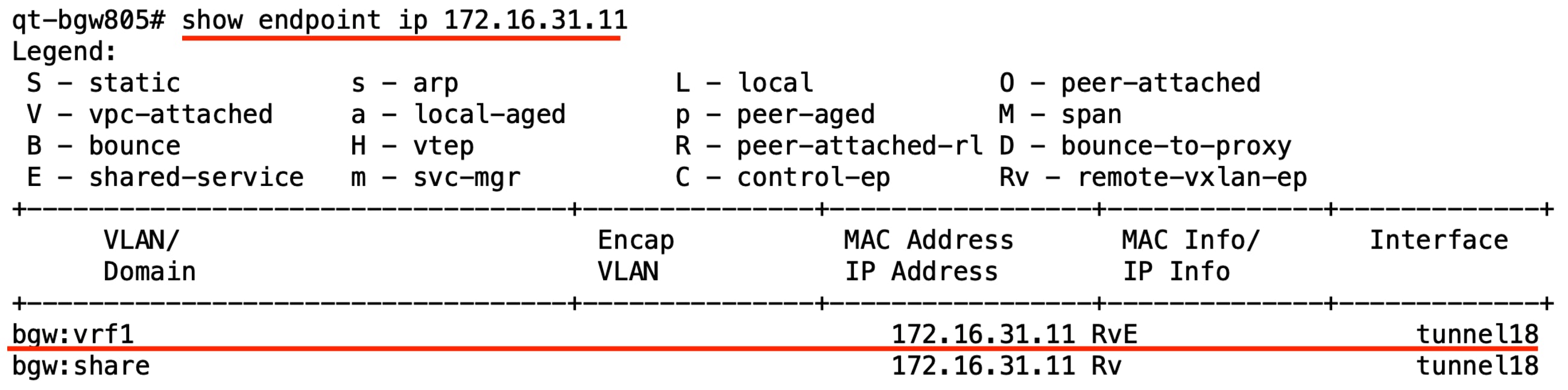
Figure 377. ACI Site 2 Border Gateway learns remote endpoint across VRF
Data Plane Verification
The figure below shows the endpoints used in this use case.
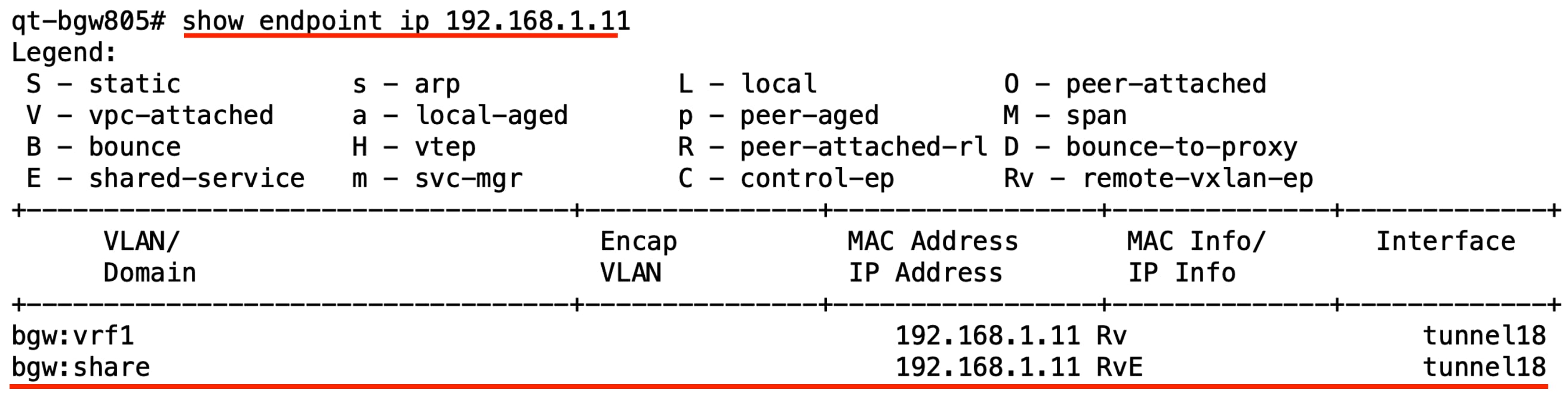
Figure 378. Endpoint communication across VRFs across Sites
The figure below illustrates the policy enforcement location and VNI translation behavior for traffic from 192.168.1.11 (VRF vrf1) in ACI Site 1 to 172.16.31.201 (VRF share) in ACI Site 2. In the case of inter-VRF communication, ingress compute leaf performs “VRF switch” also known as VRF re-write, from the source VRF to the destination VRF using the local source and destination VNI numbers, since the compute leaf is not aware of the normalized VNI.
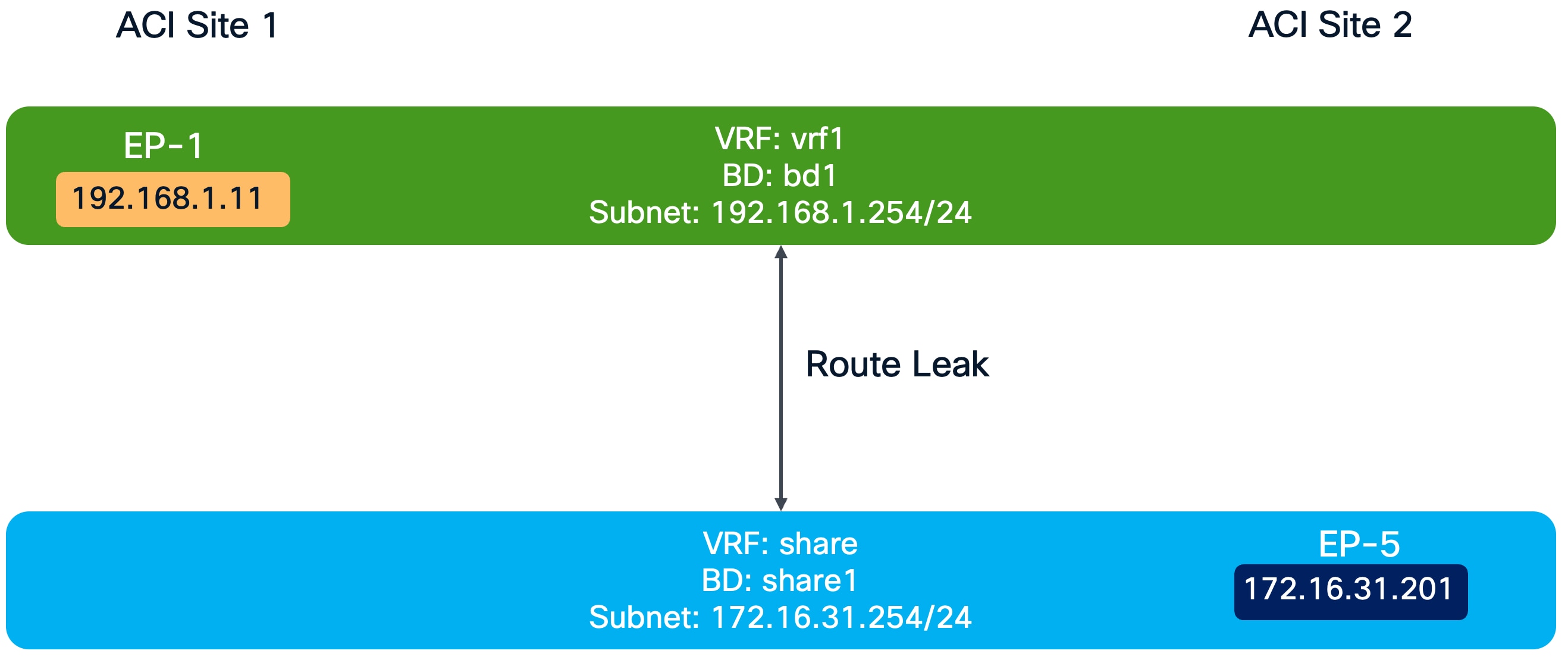
Figure 379. ACI Site 1 VRF vrf1 to ACI Site 2 VRF share, ingress leaf performs VRF switch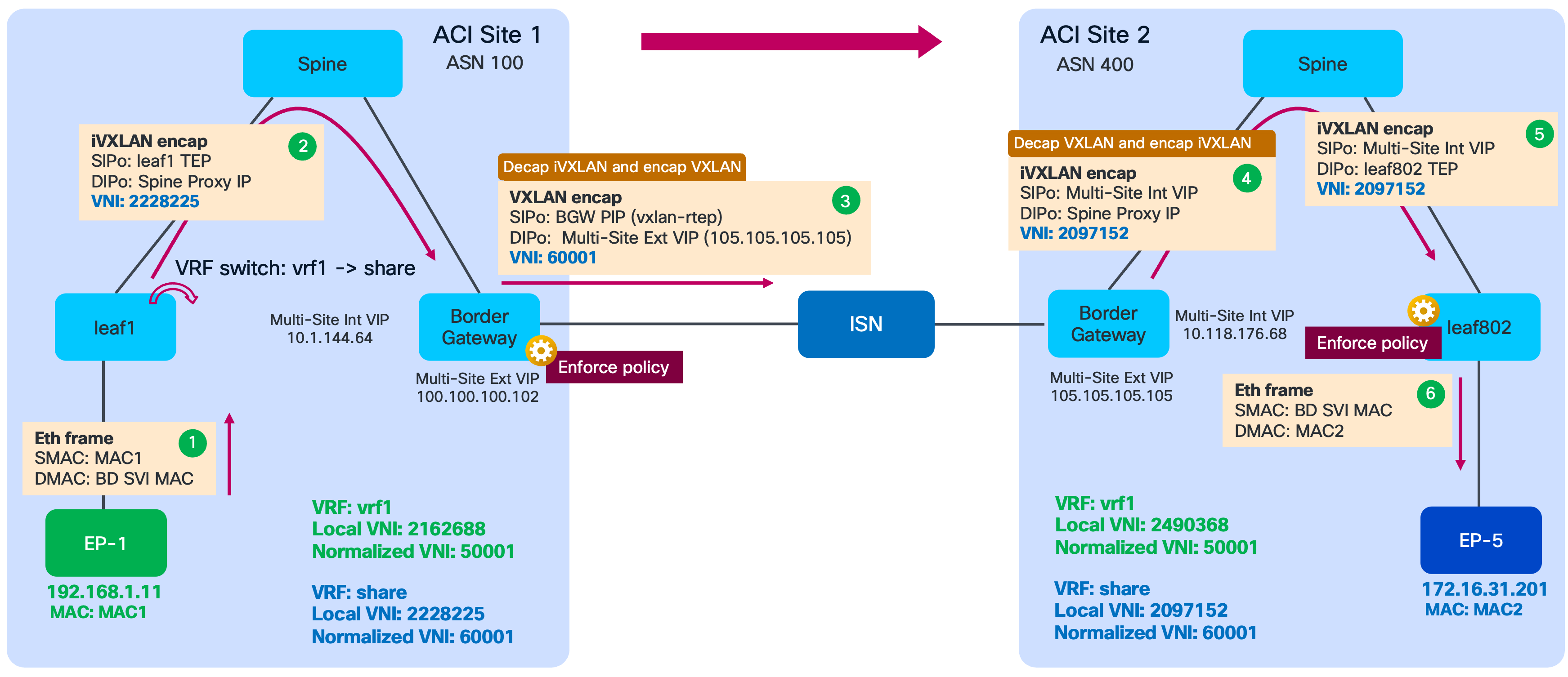
Figure 380. ACI Site 2 VRF share to ACI Site 1 VRF vrf1, ingress leaf performs VRF switch
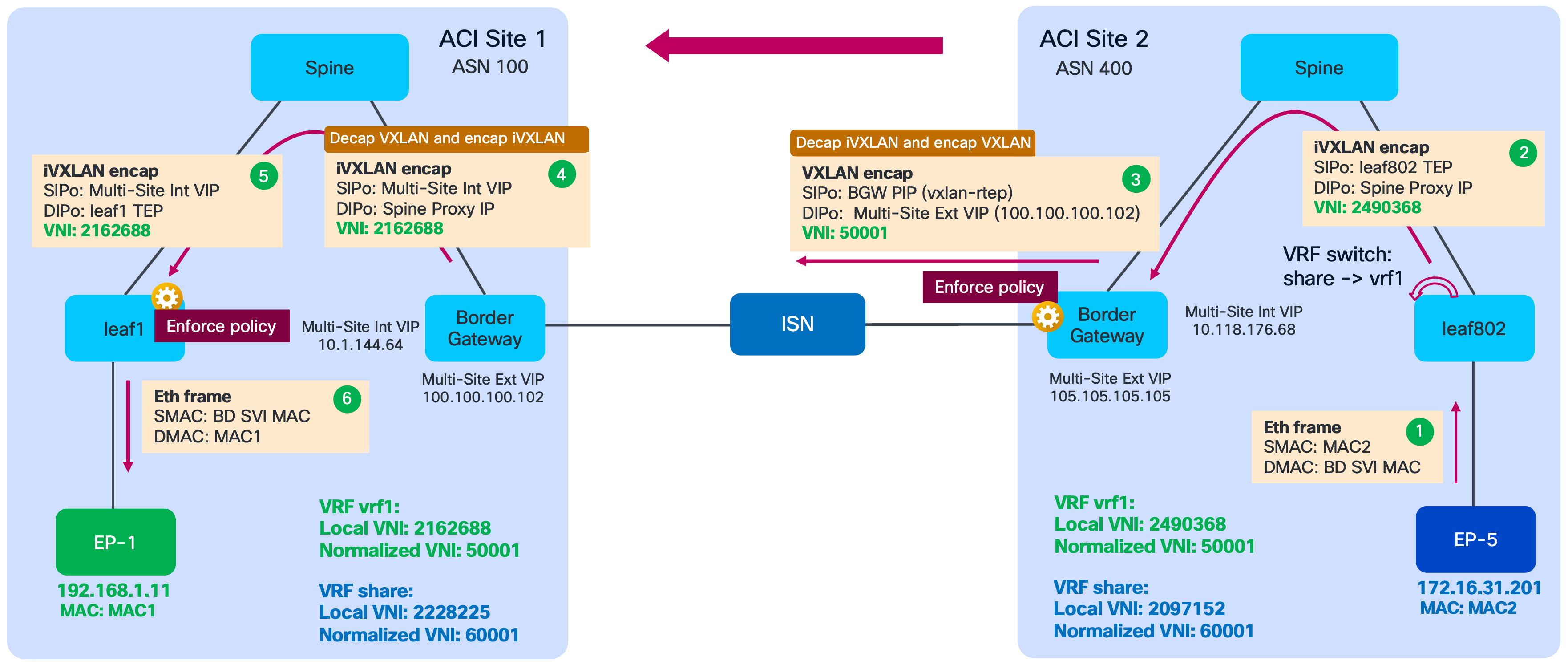
Figure 381. Data plane Shared service communication
Ping from 192.168.1.11 in ACI Site 1 VRF vrf1 to 172.16.31.201 in ACI Site 2 VRF share. The packet capture of the ICMP request from EP-1 to EP-5 confirms that the Layer 3 (VRF) Normalized VNI of the destination VRF (VRF share) is used in the VXLAN header for inter-site data plane forwarding.
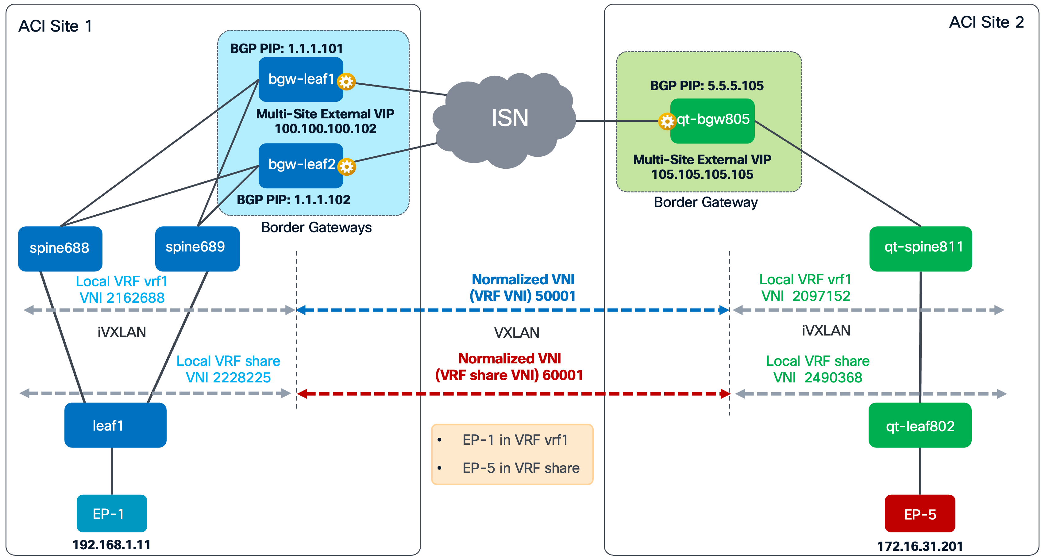
Figure 382. ICMP request from EP-1 (192.168.1.11) to EP-5 (172.16.31.201)
The packet capture of the ICMP reply from EP-5 to EP-1 confirms that the Layer 3 (VRF) Normalized VNI of the destination VRF (VRF vrf1) is used in the VXLAN header for inter-site data plane forwarding.
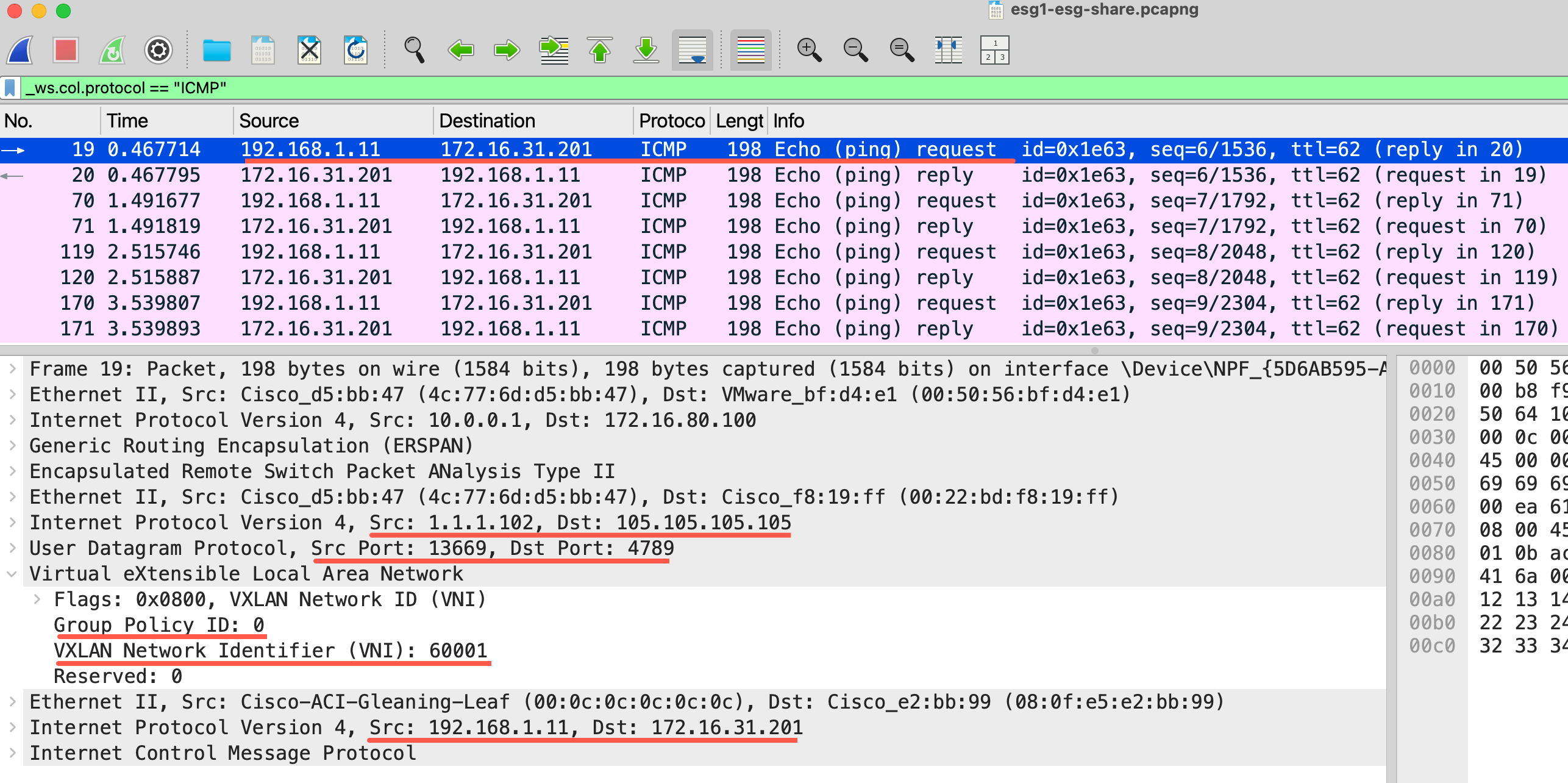
Figure 383. ICMP reply from EP-5 (172.16.31.201) to EP-1 (192.168.1.11)
The figure below illustrates the policy enforcement location for traffic from 192.168.1.11 (endpoint in ESG esg1 in VRF vrf1) in ACI Site 1 to 172.16.31.201 (endpoint in ESG share in VRF share) in ACI Site 2.
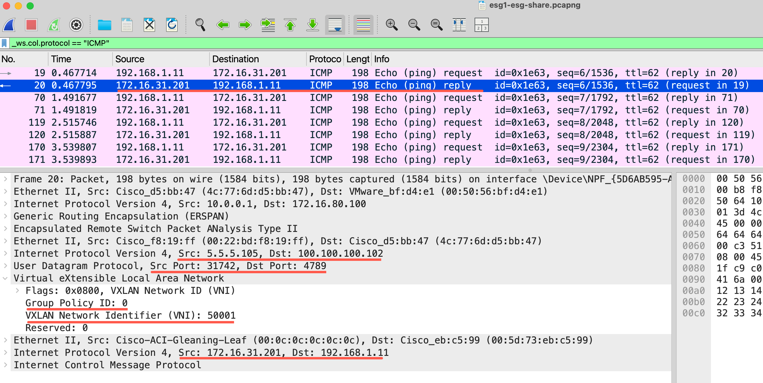
Figure 384. Policy enforcement VRF vrf1 to VRF share, from ACI Site 1 to ACI Site 2
As outlined in the Data Plane verification, the compute leaf at the source site (Site 1 in this flow) performs a VRF switch from VRF vrf1 to VRF share. Following this VRF switch, the policy enforcement aligns with the behavior described in Use Case 2: Inter-Subnet Communication Stretched BDs Multiple ESGs. Specifically, for traffic flowing from ACI Site 1 to ACI Site 2 (from VRF vrf1 to VRF share):
● ACI Site 1 Border Gateway applies policy in VRF share
● ACI Site 2 Compute Leaf applies policy in VRF share
The figure below illustrates the policy enforcement location for traffic from 172.16.31.201 (endpoint in ESG share in VRF share) in ACI Site 2 to 192.168.1.11 (endpoint in ESG esg1 in VRF vrf1) in ACI Site 1.
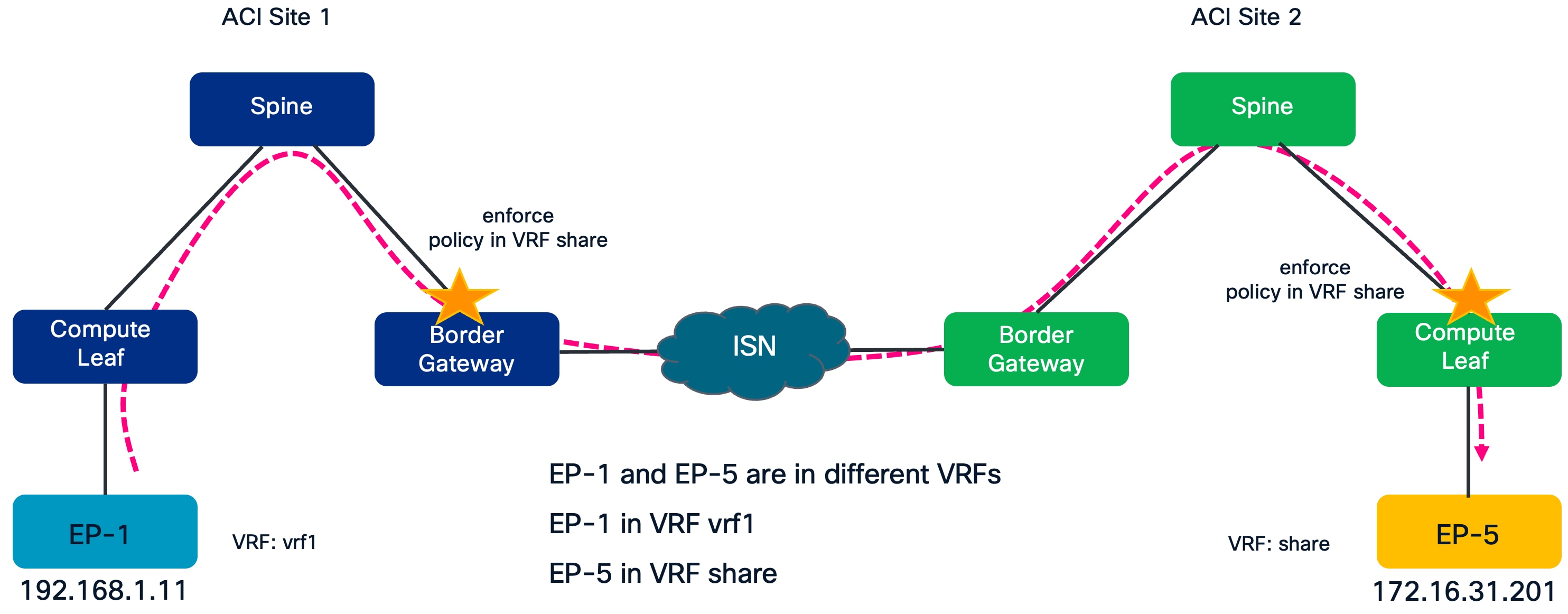
Figure 385. Policy enforcement VRF share to VRF vrf1, from ACI Site 2 to ACI Site 1
Similarly, the compute leaf at the source site (Site 2 in this flow) performs a VRF switch from VRF share to VRF vrf1. Following this VRF switch, the policy enforcement aligns with the behavior described in Use Case 2: Inter-Subnet Communication Stretched BDs Multiple ESGs. Specifically, for traffic flowing from ACI Site 2 to ACI Site 1 (from VRF share to VRF vrf1):
● ACI Site 2 Border Gateway applies policy in VRF vrf1
● ACI Site 1 Compute Leaf applies policy in VRF vrf1
Use Case 10: Inter-VRF Communication (Shared Services) with Non-stretched BDs
This use case is similar to Use Case 9: Inter-VRF Communication (Shared Services) with Stretched BDs. The main difference is that, in this case, both Bridge Domains (BDs) are non-stretched and are deployed locally at each site. A normalized VNI is still configured when each BD is deployed on the local Border Gateway; however, the normalized VNI values are different between the two sites.
The figure below illustrates an example used in the section.
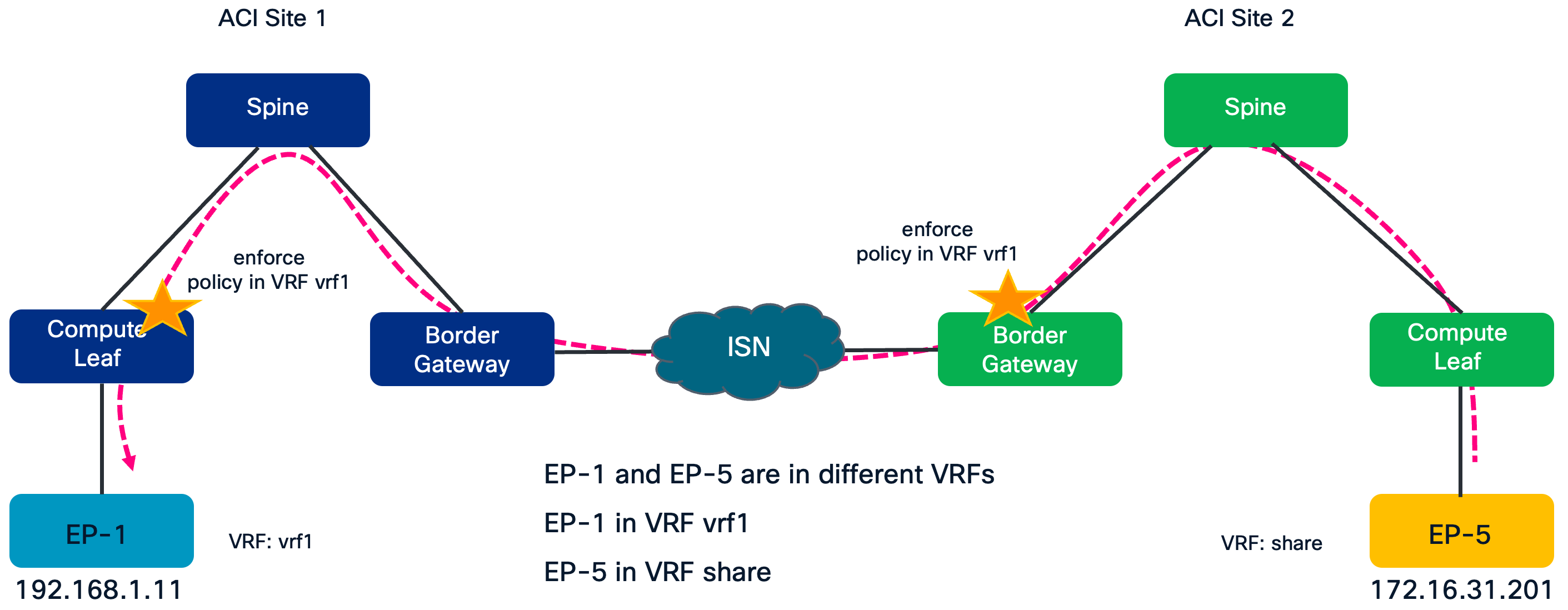
Figure 386. Shared Service with Non-stretched BDs
Most of the required objects were created in the previous use cases. Bridge Domain (BD) bd50 and ESG esg50 were introduced in Use Case 4: Inter-Subnet Communication with Non-Stretched BDs and Multiple ESGs. This section focuses on the new objects introduced for this use case, including ESG share2 in ACI Site 1, and BD bd-share2 and ESG share2 in ACI Site 2.
The route leaking configuration is similar to that described in Use Case 9: Inter-VRF Communication (Shared Services) with Stretched BDs. Any differences specific to this use case are called out explicitly.
The BD bd50, ESG esg50 were created in the previous Use Case 4: Inter-Subnet Communication with Non-stretched BDs Multiple ESGs.
For the purpose of completion, the required configuration steps are as follows:
On ACI Site 1:
● Create BD bd50, with subnet “Advertised Externally” scope enabled. Without “Advertised Externally” scope enabled, Border Gateway does not advertise Type-5 route through BGP EVPN.
● Create ESG esg50 with normalized pcTag 1050 and selector EPG epg50.
● Create ESG share2 with normalized pcTag 2002 and no ESG need selectors configured.
● Configure route leak between VRF vrf1 and VRF share, make sure the leaked subnet cover /32 host routes:
◦ leak Internal Prefix 192.168.50.0/24 with “Less Than or Equal (Prefix)” of 32 from VRF vrf1 to VRF share
◦ leak Internal Prefix 172.16.32.0/24 with “Less Than or Equal (Prefix)” of 32 from VRF share to VRF vrf1
● Apply a contract with tenant scope between esg50 and share2
On ACI Site 2:
● Create BD bd-share2, with subnet “Advertised Externally” scope enabled. Without “Advertised Externally” scope enabled, Border Gateway does not advertise Type-5 route through BGP EVPN.
● Deploy the Bridge Domain bd-share2 on the Border Gateway by associating it with the Border Gateway Set. You may assign a Normalized VNI but note that this value does not exist on Site 1.
● Create ESG share2 with normalized pcTag 2002 and selector EPG share2.
● Create ESG esg50 with normalized pcTag 1050 and no ESG need selectors configured.
● Configure route leak between VRF vrf1 and VRF share, make sure the leaked subnet cover /32 host routes.
◦ leak Internal Prefix 192.168.50.0/24 with less “Less Than or Equal (Prefix)” of 32 from VRF vrf1 to VRF share
◦ leak Internal Prefix 172.16.32.0/24 with less “Less Than or Equal (Prefix)” of 32 from VRF share to VRF vrf1
● Apply a contract with tenant scope between esg50 and share2.
Create Provider VRF and Bridge Domain
Note that the Bridge Domain (BD) bd50 was previously created on Site 1 in Use Case 4: Inter-Subnet Communication with Non-Stretched BDs and Multiple ESGs.
Please verify that the BD subnet has the “Advertised Externally” scope enabled. Since bd50 is local to Site 1, if the “Advertised Externally” scope is not enabled, the BD subnet 192.168.50.0/24 will not be advertised to Site 2 through BGP EVPN.
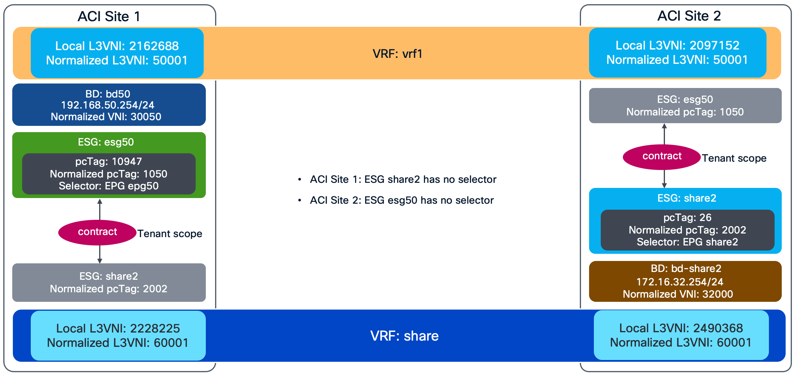
Figure 387. ACI Site 1 bd50 subnet Advertised Externally scope enabled
The figures below are BD bd-share2 configurations in ACI Site 2.
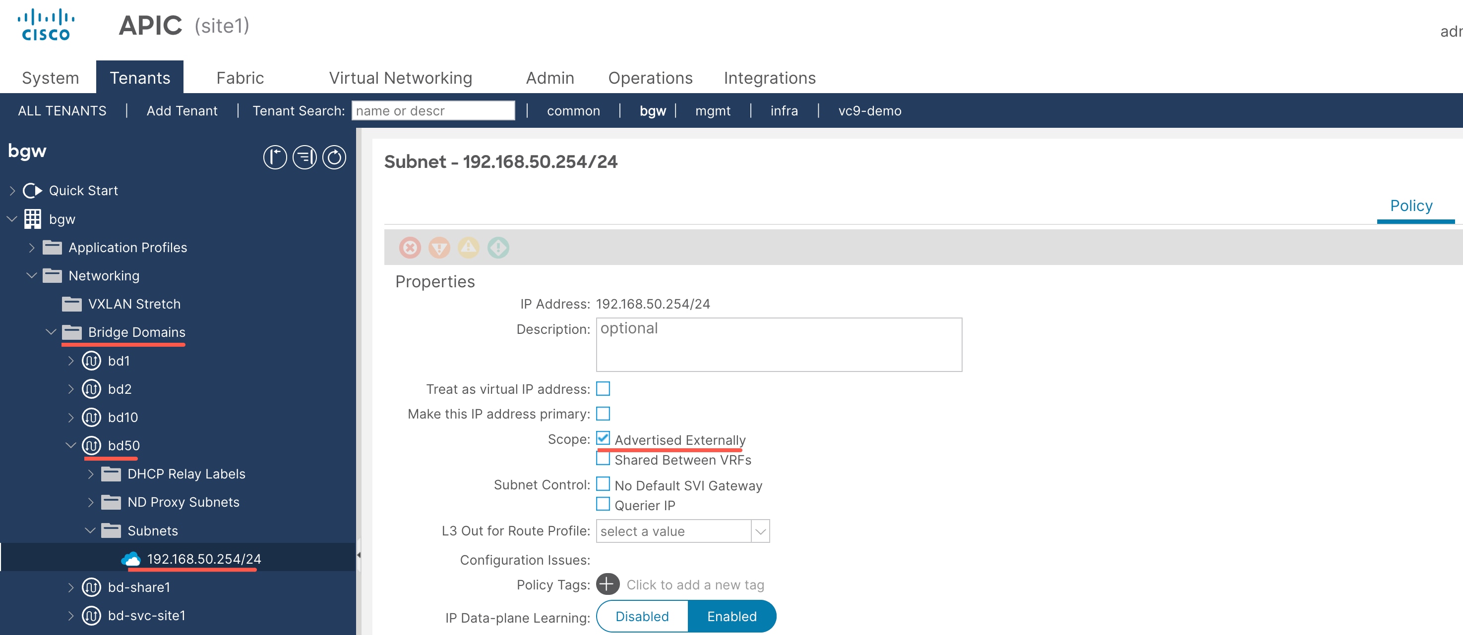
Figure 388. ACI Site 2 BD bd-share2
Ensure that the BD subnet has the “Advertised Externally” scope enabled. Since bd-share2 is local to Site 2, if the “Advertised Externally” scope is not enabled, the BD subnet 172.16.32.0/24 will not be advertised to Site 1 through BGP EVPN.
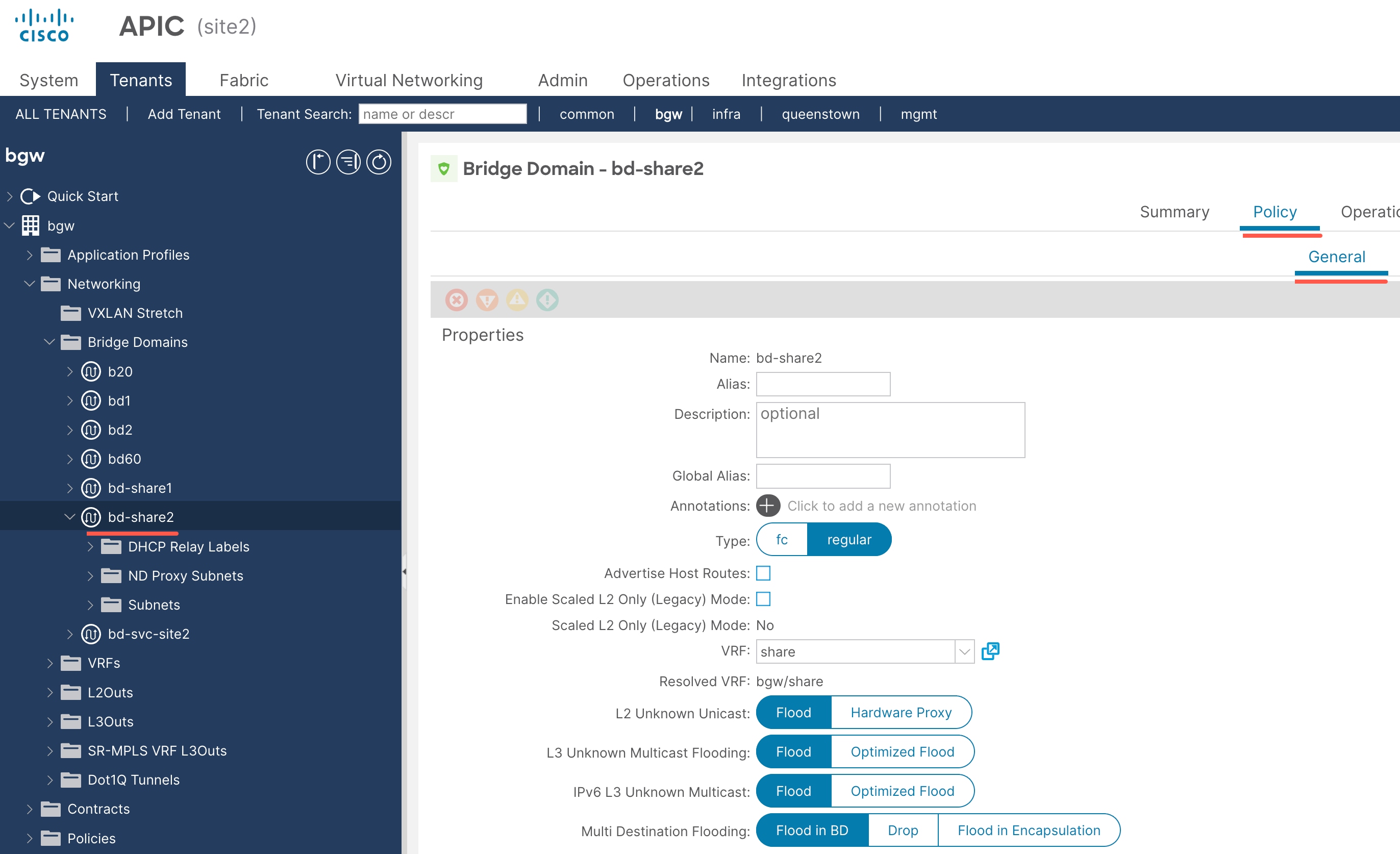
Figure 389. ACI Site 2 bd-share2 subnet Advertised Externally scope enabled
On Site 2, deploy the Bridge Domain bd-share2 on the Border Gateway by associating it with the Border Gateway Set. The normalized VNI 32000 does not exist in Site 1.
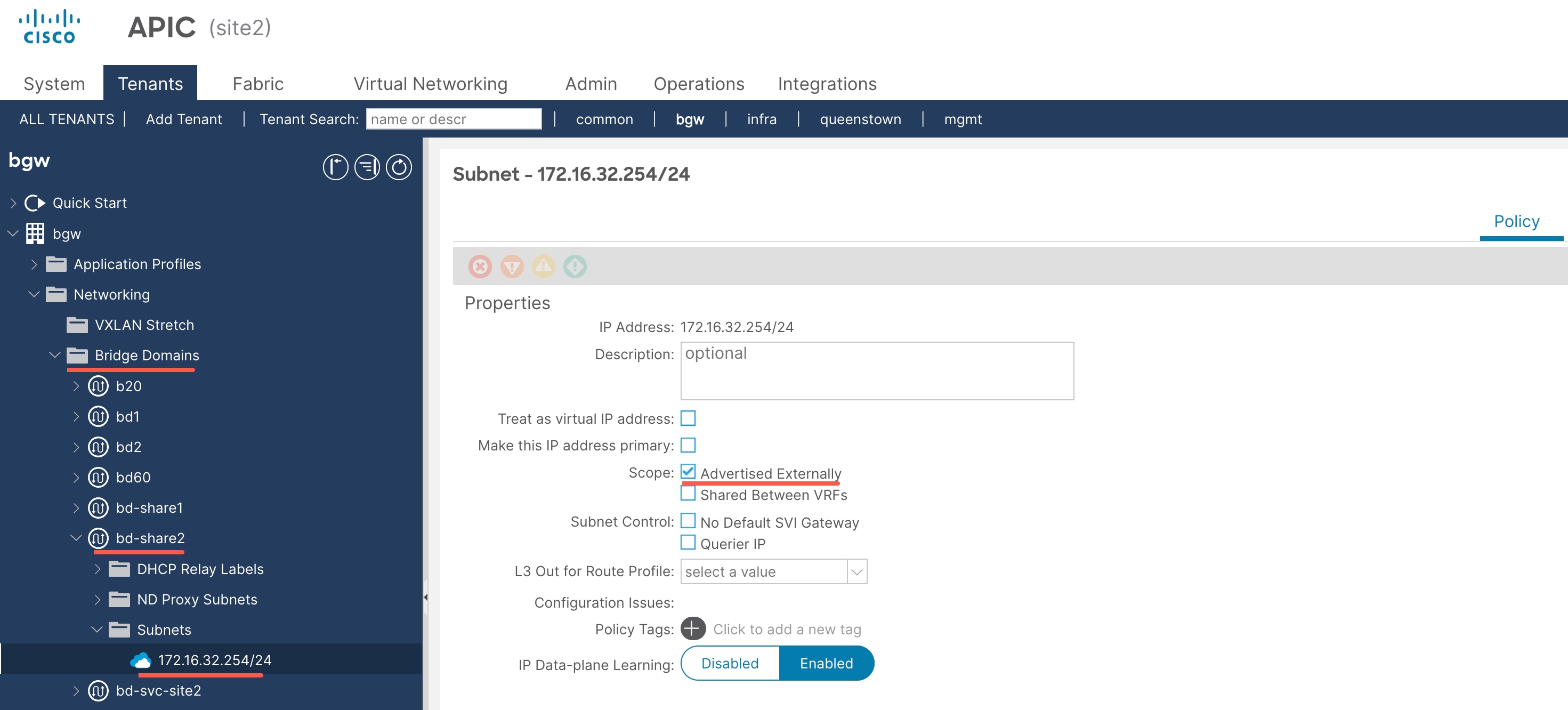
Figure 390. ACI Site 2 deploy BD bd-share2 to Border Gateway
On both ACI Site 1 and Site 2, ESG esg50 were already created in Use Case 4: Inter-Subnet Communication with Non-Stretched BDs and Multiple ESGs. They are shown here for completeness. ESG esg50 uses 1050 as the Normalized pcTag.
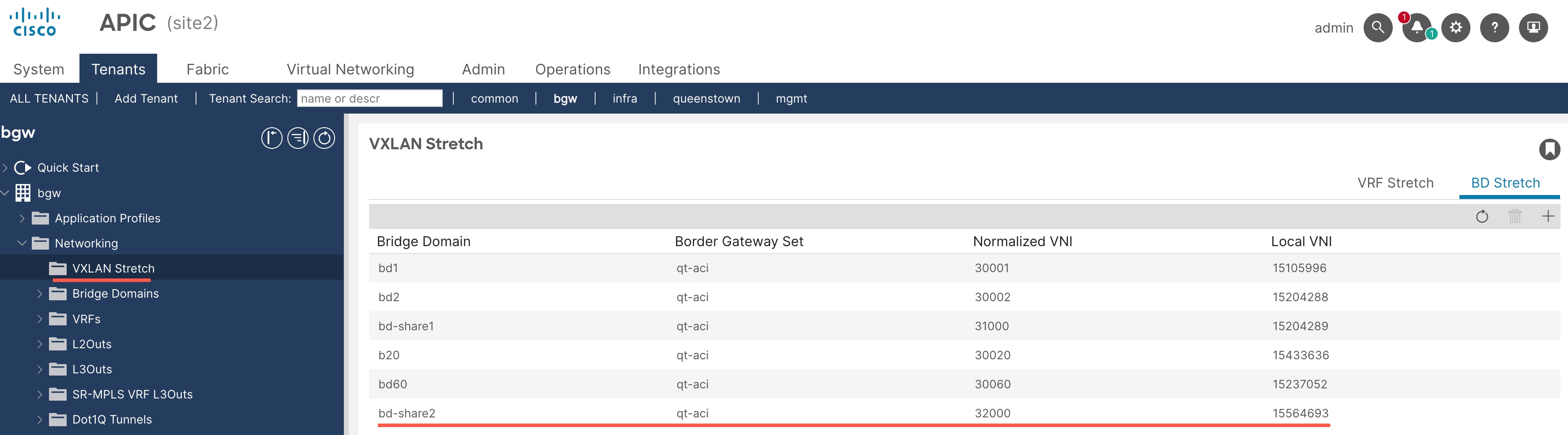
Figure 391. ACI Site 1 ESG esg50 Normalized pcTag
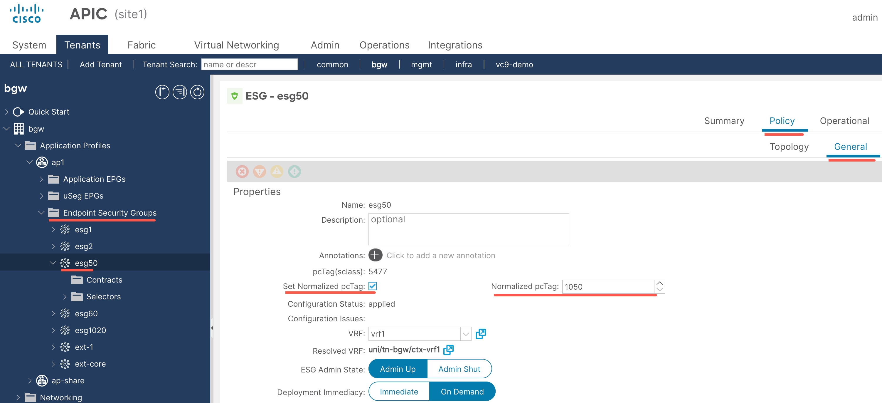
Figure 392. ACI Site 2 ESG esg50 Normalized pcTag
Although the Bridge Domain bd-share2 is deployed locally only in Site 2, it is necessary to create the Endpoint Security Group (ESG) share2 in Site 1 with the same normalized pcTag as the ESG share2 in Site 2. The ESG share2 in Site 1 does not have an ESG selector and is used solely to classify traffic originating from the ESG share2 in Site 1. The figures below are ESG share2 configurations in ACI Site 1.
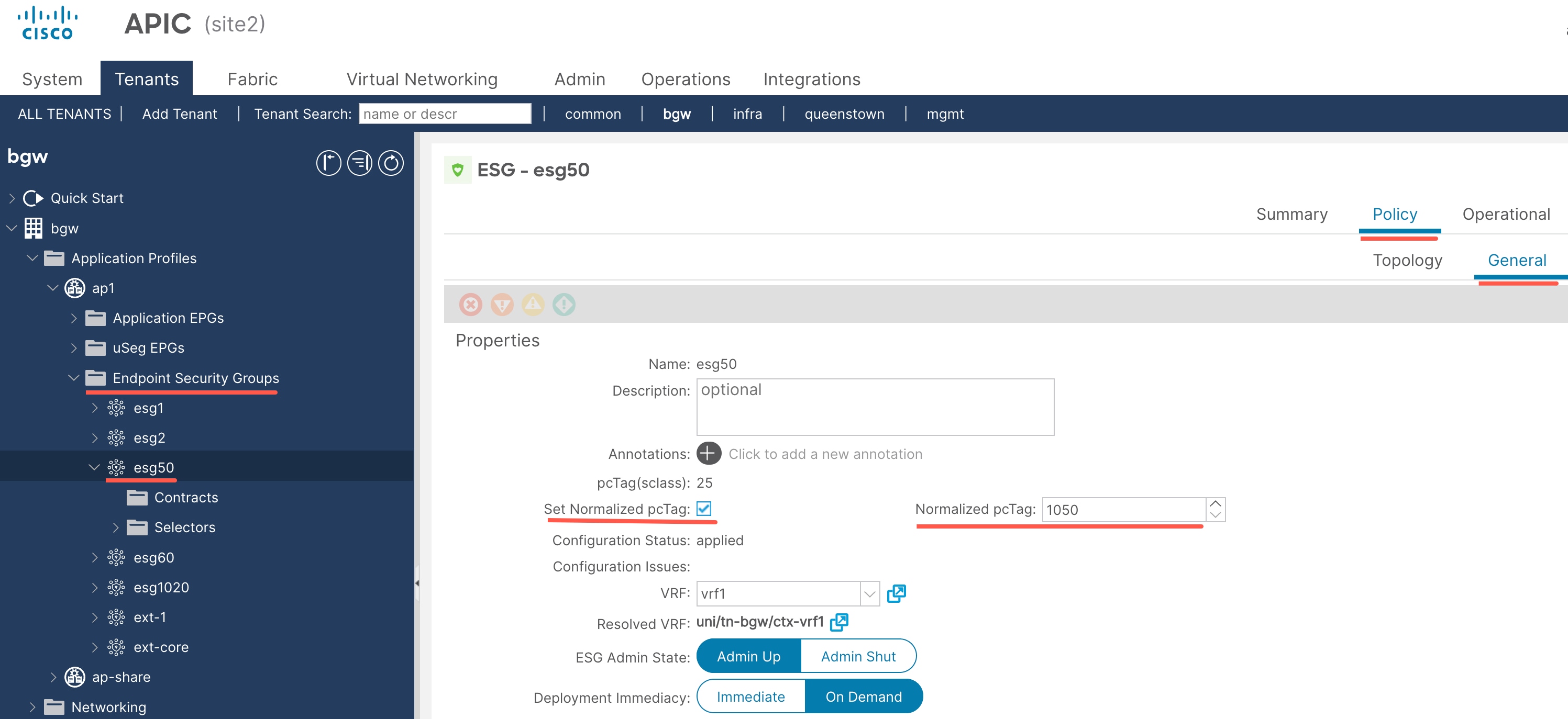
Figure 393. ACI Site 1 ESG share2 without selector
ACI Site 1 ESG share2 Normalized pcTag is set to 2002, later the same normalized value is used for ESG share2 in ACI Site 2.
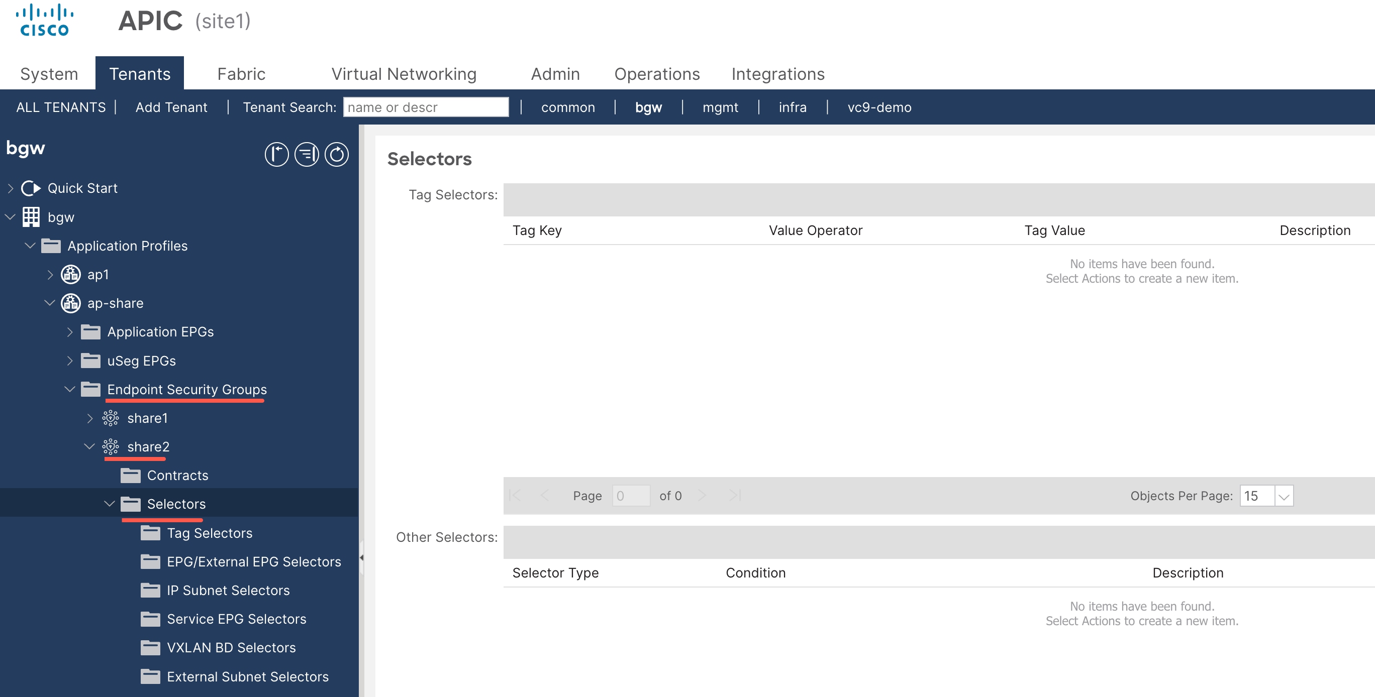
Figure 394. ACI Site 1 ESG share2 Normalized pcTag
The figures below are ESG share2 configurations in ACI Site 2.
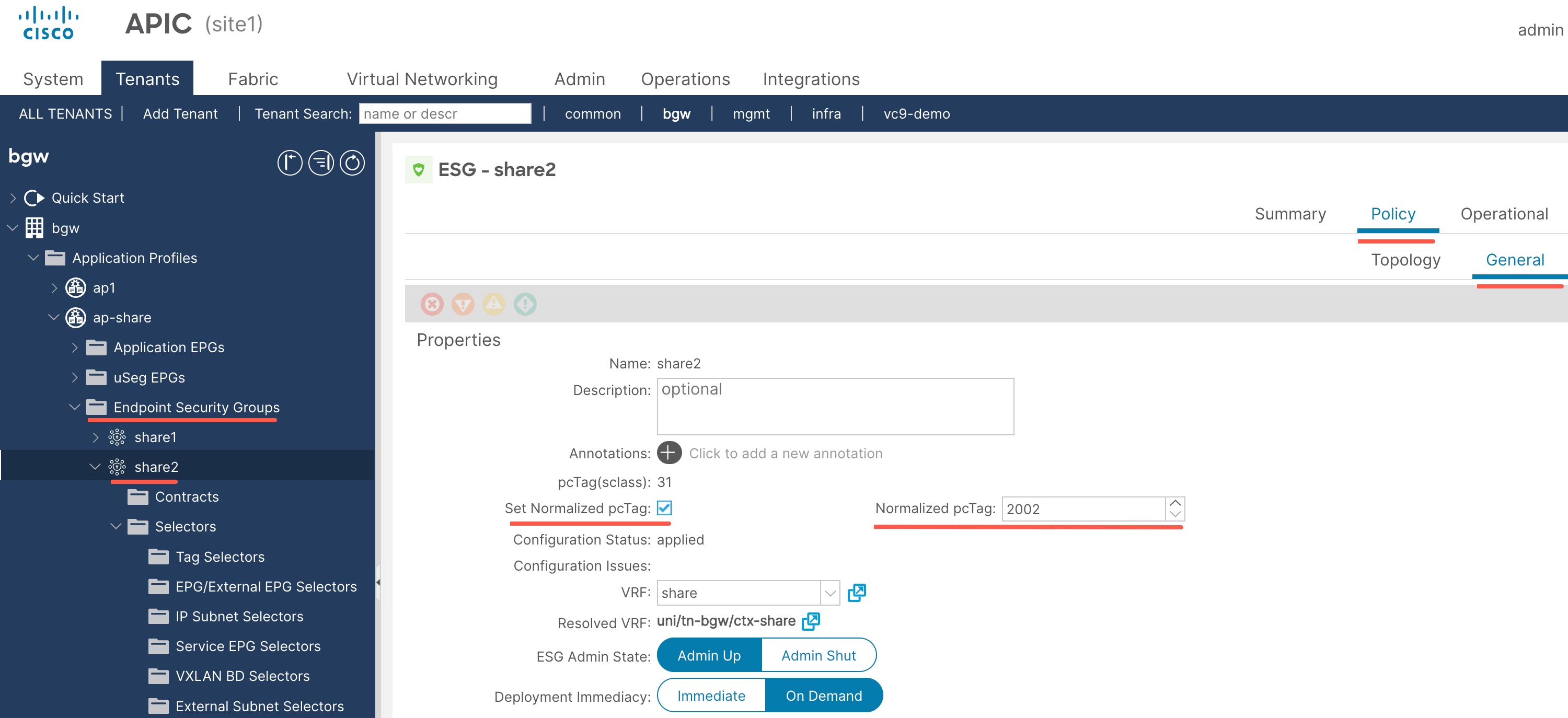
Figure 395. ACI Site 2 ESG share2 with EPG share2 as selector
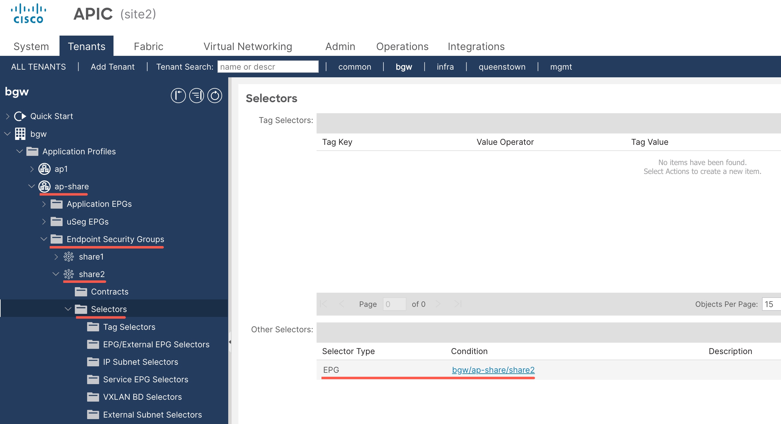
Figure 396. ACI Site 2 ESG share2 Normalized pcTag
Create and Apply Tenant Scope Contract
On both ACI Sites, create a tenant-scope contract named “esg50-share2”. Apply the contract esg50-share2 to ESG esg50 and ESG share2, making esg50 the contract consumer and share2 the contract provider. The figures below are contract configurations in ACI Site 1. Note that the contract scope is set to “Tenant” instead of “VRF” because it is for inter-VRF communication for ESGs in the same tenant.
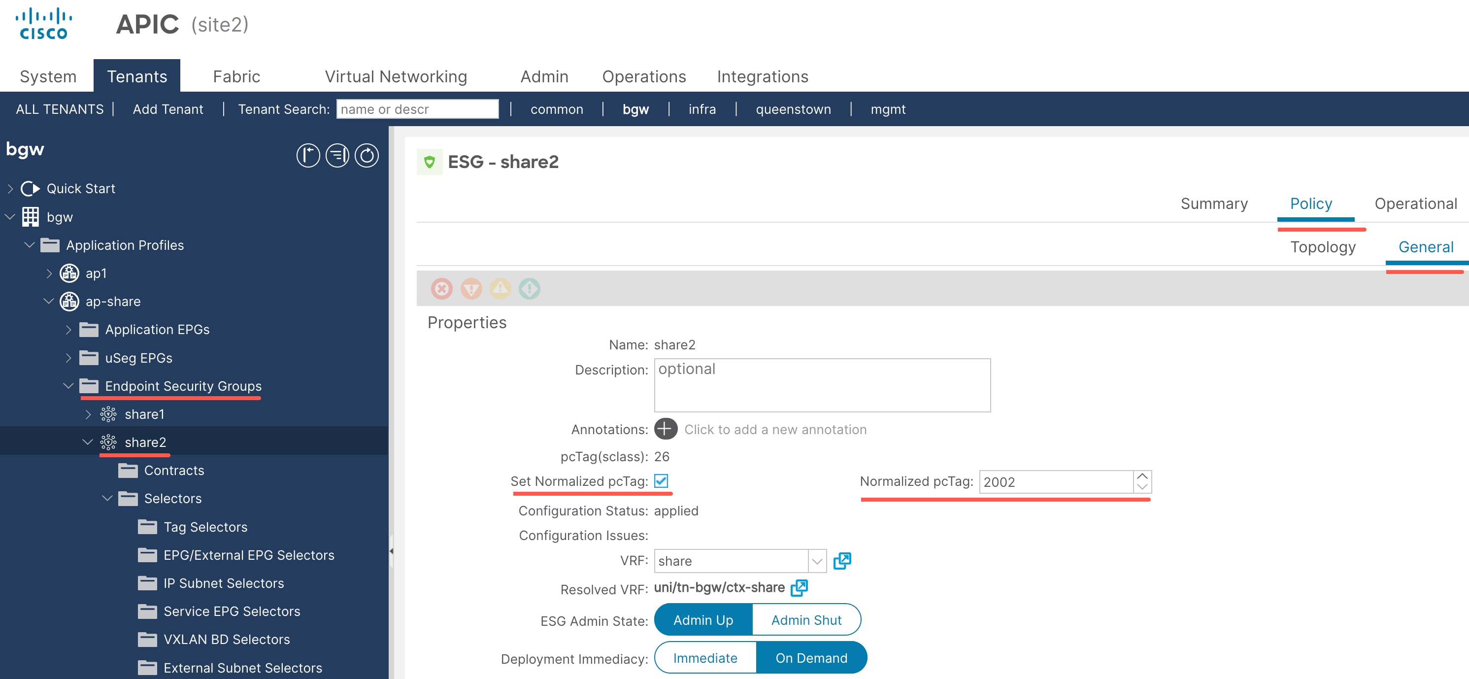
Figure 397. ACI Site 1 tenant scope contract esg50-share2
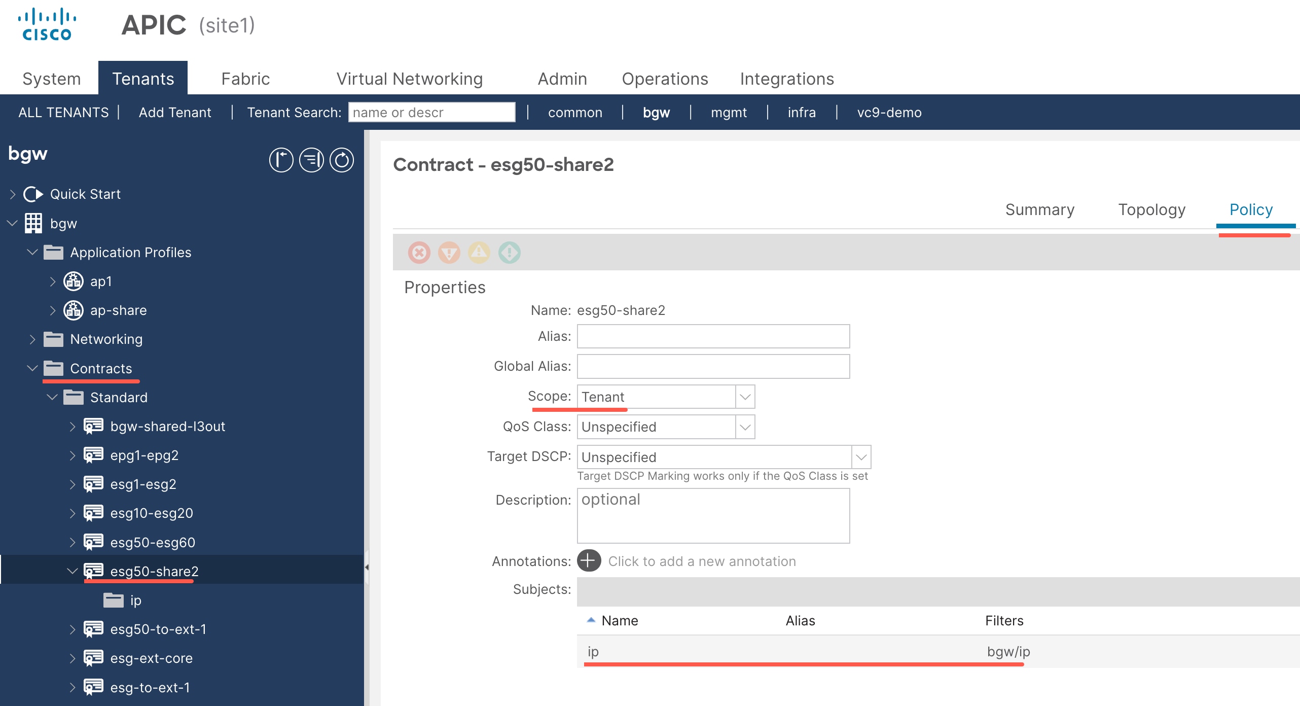
Figure 398. ACI Site 1 ESG esg50 contract consumer
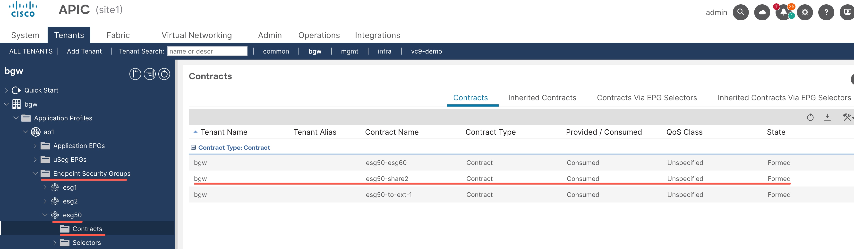
Figure 399. ACI Site 1 ESG share2 contract provider
The figures below are contract configurations in ACI Site 2.
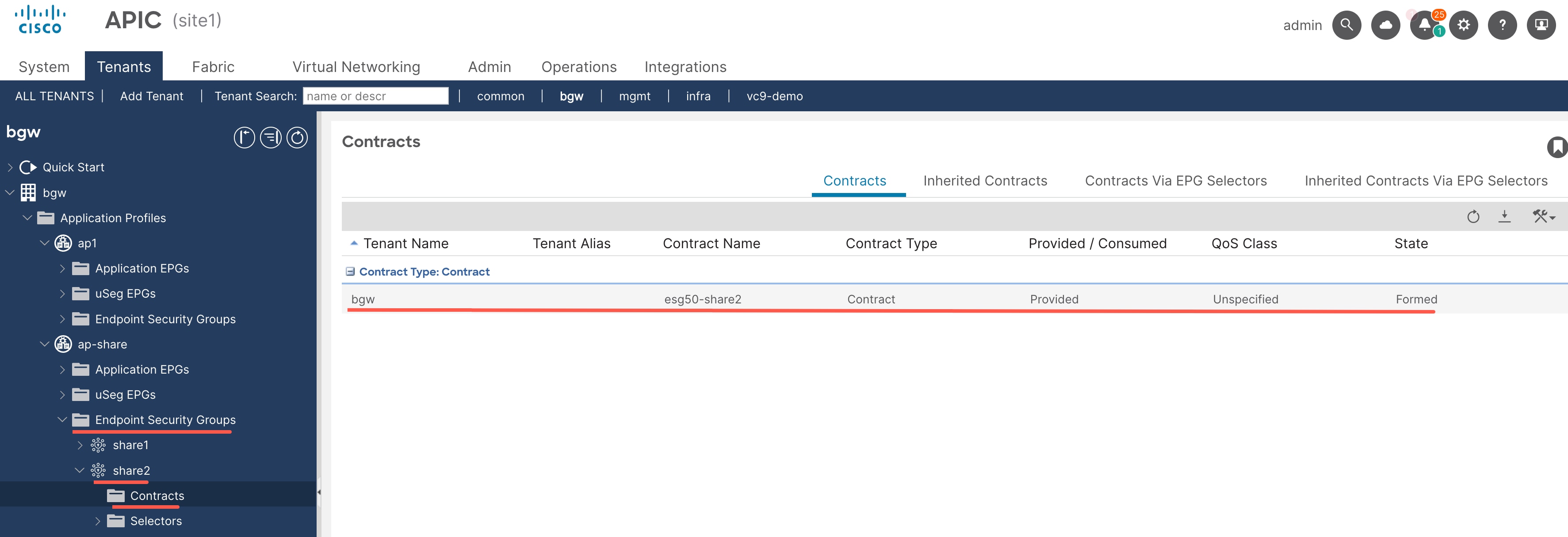
Figure 400. ACI Site 2 tenant scope contract esg50-share2
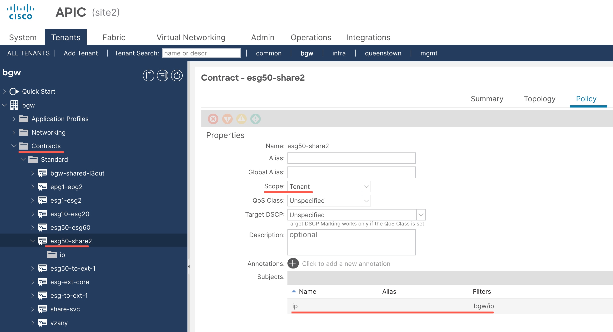
Figure 401. ACI Site 2 ESG esg50 contract consumer
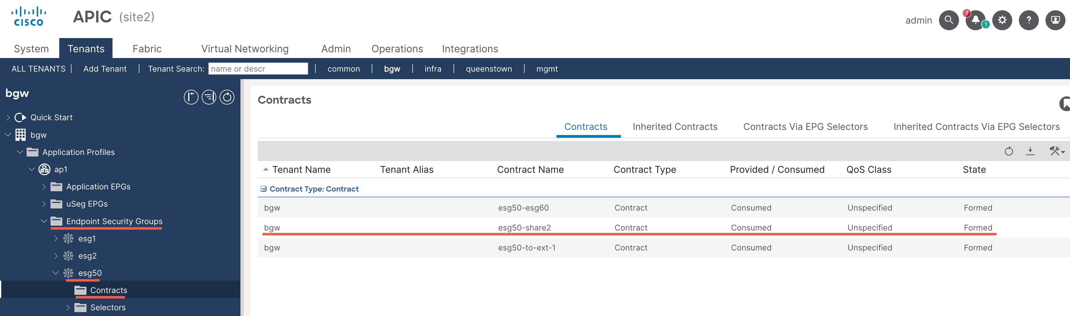
Figure 402. ACI Site 2 ESG share2 contract provider
Although the tenant-scope contract between ESGs was created in the previous step to define the security policies allowing communication, this contract alone does not establish network connectivity between the endpoints. Because the endpoints reside in different VRFs, route leaking must be configured to enable routing reachability between these VRFs. Without this route leaking configuration, the endpoints cannot communicate despite the contract being in place.
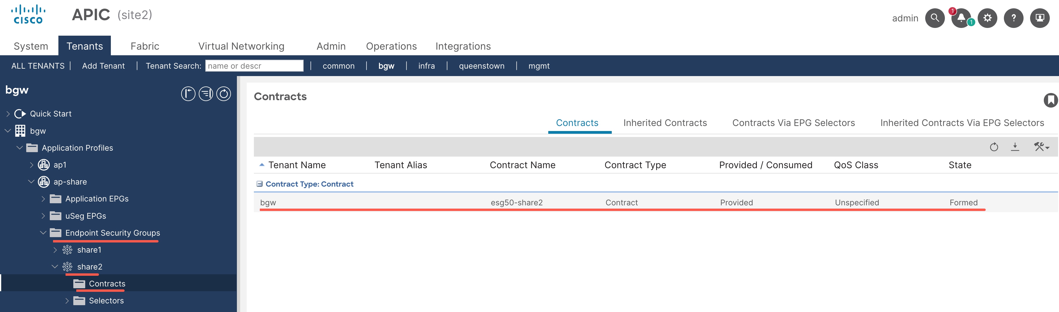
Figure 403. Route Leak diagram
The next step is to configure route leaking between VRF vrf1 and VRF share. This involves leaking the subnet 192.168.50.0/24 from VRF vrf1 to VRF share, and the subnet 172.16.32.0/24 from VRF share to VRF vrf1. It is essential to ensure that the route leak covers not only the /24 prefixes but also the /32 host routes. This guarantees that host routes can be exchanged across VRFs and sites, allowing the destination to program the host route in its respective routing table with the appropriate pcTag for policy enforcement. Since this configuration is similar to Use Case 9: Inter-VRF Communication (Shared Services) with Stretched BDs, this section presents the configuration results rather than the detailed steps.
On ACI Site 1, leak Internal Prefix 192.168.50.0/24 from VRF vrf1 to VRF share.
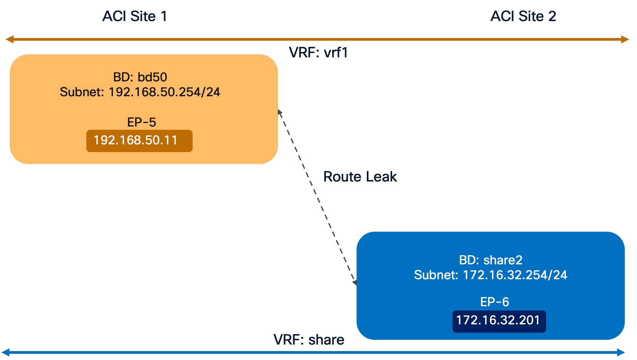
Figure 404. ACI Site 1 leak prefix 192.168.50.0/24 from VRF vrf1 to VRF share
On ACI Site 1, leak Internal Prefix 172.16.32.0/24 from VRF share to VRF vrf1.
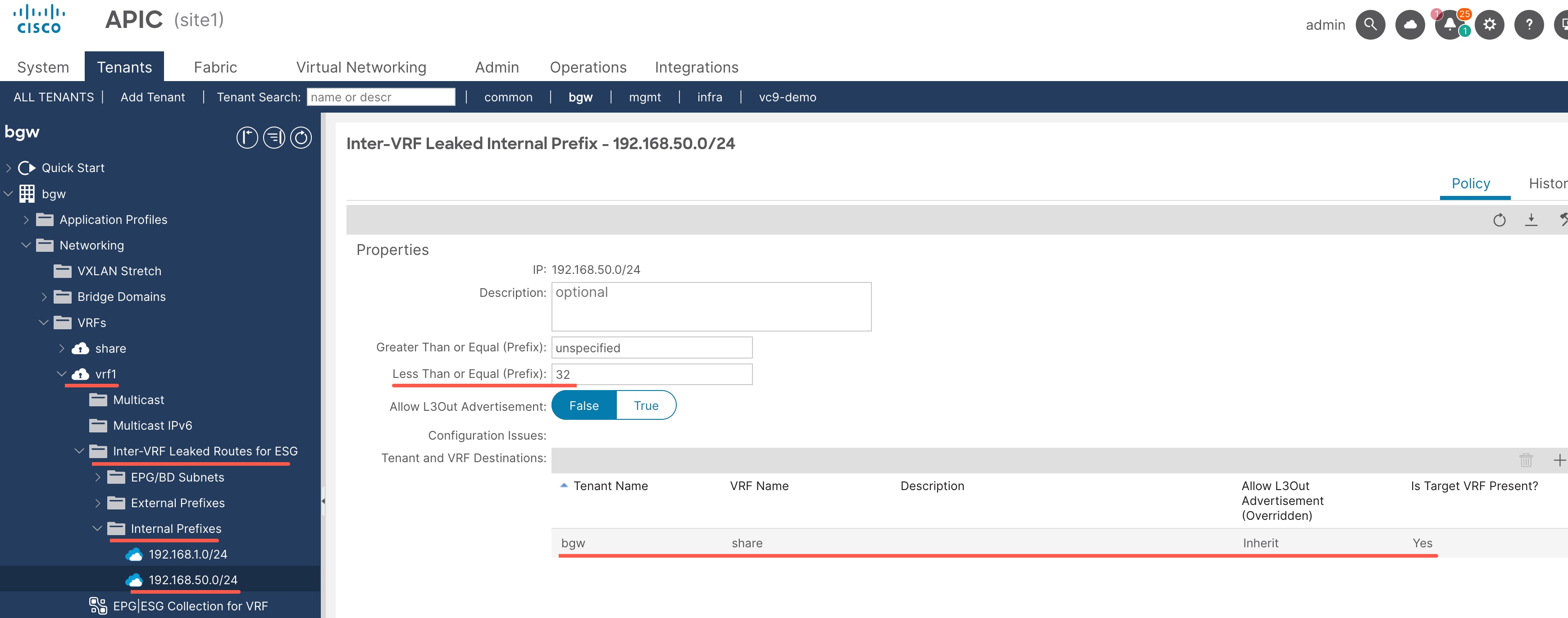
Figure 405. ACI Site 1 leak prefix 172.16.32.0/24 from VRF share to VRF vrf1
On ACI Site 2, leak Internal Prefix 192.168.50.0/24 from VRF vrf1 to VRF share.
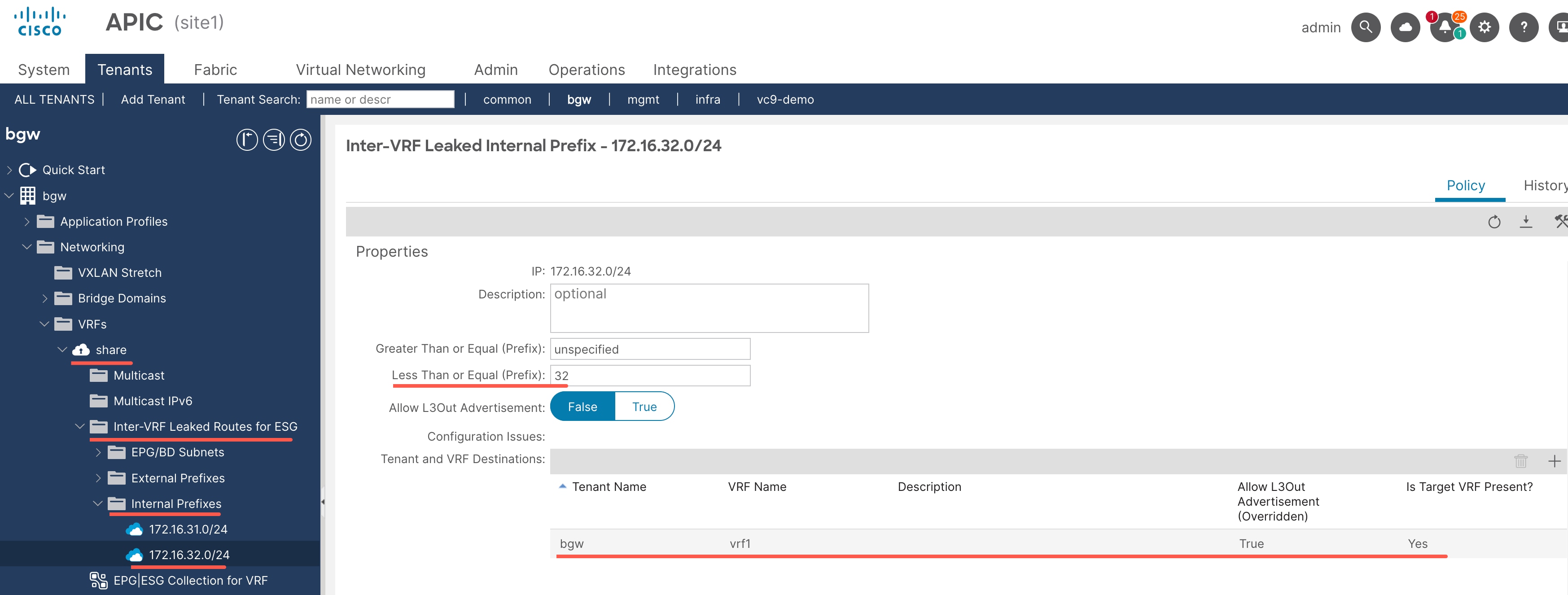
Figure 406. ACI Site 2 leak prefix 192.168.50.0/24 from VRF vrf1 to VRF share
On ACI Site 2, leak Internal Prefix 172.16.32.0/24 from VRF share to VRF vrf1.
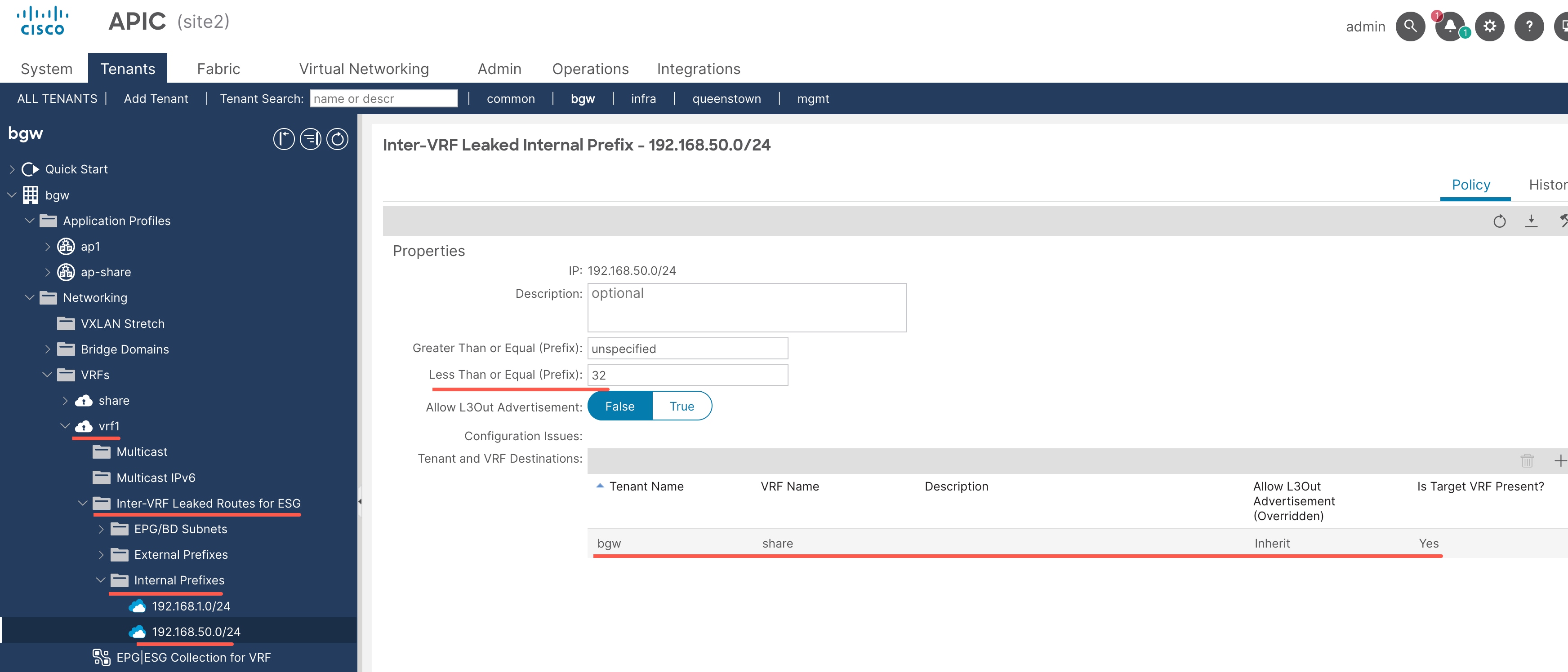
Figure 407. ACI Site 2 leak prefix 172.16.32.0/24 from VRF share to VRF vrf1
Control Plane Verification
The following figure illustrates IP subnets used in this verification section. Note that BD bd50 is local to ACI Site 1, BD bd-share2 is local to ACI Site 2.
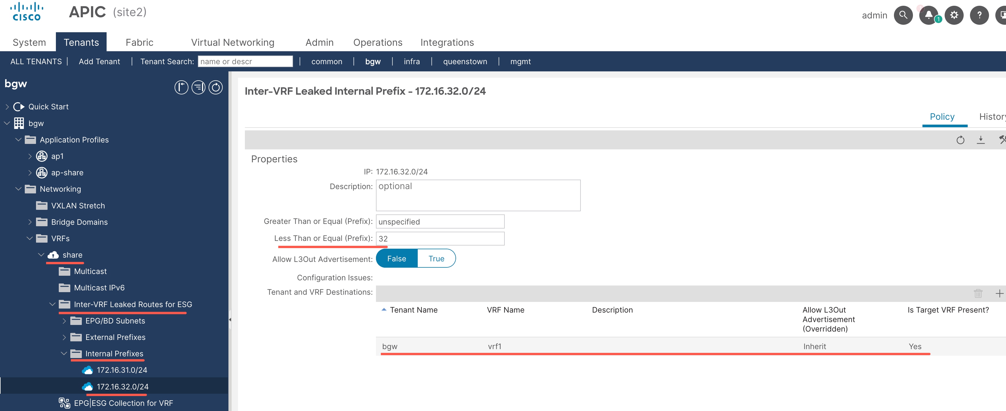
Figure 408. Route Leak diagram
Note that route leaking depends on the configuration of each site. Specifically, regardless of the configuration on Site 2, the subnet 172.16.32.0/24 is leaked from VRF share to VRF vrf2 on Site 1 only if the route leak configuration is completed on Site 1 itself. On ACI Site 2, compute leaf has the route 172.16.32.0/24 in VRF vrf1.
Since both VRFs are stretched, EVPN Routes Type 5 are advertised by default across sites within the same VRF, provided that the Bridge Domain (BD) subnets have the “Advertised Externally” scope enabled. Specifically, Site 1 Border Gateways learn the 172.16.32.0/24 route in VRF share, while Site 2 Border Gateways learn the 192.168.50.0/24 route in VRF vrf1. Once these routes are learned, route leaking is initiated by the route leak configuration on the local site.
Also note that although BDs are not stretched, they are deployed on Border Gateways so that EVPN Type-2 routes for endpoints are always exchanged between sites within the same VRF. For example, Site 1 Border Gateways learn the 172.16.32.201/32 host route in VRF share, and Site 2 Border Gateways learn the 192.168.50.11/32 host route in VRF vrf1.
To enable data plane communication between endpoint EP-5 (192.168.50.11) in Site 1 VRF vrf1 and endpoint EP-6 (172.16.32.201) in Site 2 VRF share, the Site 1 compute leaf must learn the 172.16.32.0/24 route in VRF vrf1, and the Site 2 compute leaf must learn the 192.168.50.0/24 route in VRF share. Additionally, the Border Gateway on each site must learn the remote endpoints from the other site to facilitate proper forwarding and policy enforcement.
Let’s verify how the route 172.16.32.0/24 is imported into VRF vrf1 on the Site 1 compute leaf.
The route 172.16.32.0/24 is advertised through BGP EVPN to Border Gateways in ACI Site 1. In vsh mode, on ACI Site 2 Border Gateway:
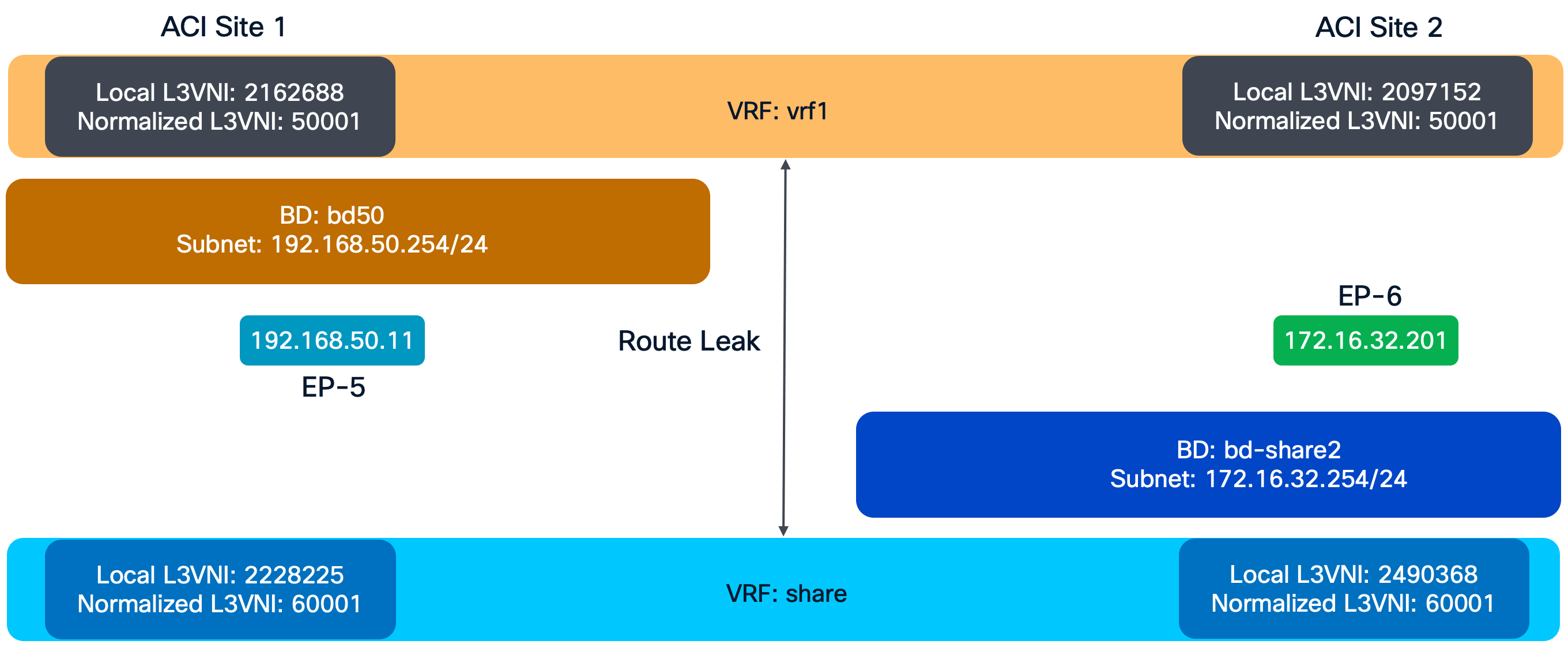
Figure 409. ACI Site 2 Border Gateway advertises EVPN Route Type 5 to Site 1 Border Gateways.
In the figure above, 1.1.1.101, 1.1.1.102, 2.2.2.202 are loopback IP of Border Gateways bgw-leaf1, bgw-leaf2, bgw-leaf202 in ACI Site 1 respectively. Site 1 Border Gateways receive route 172.16.32.0/24 through EVPN. Below is output in vsh mode of the first Border Gateway in Site 1.
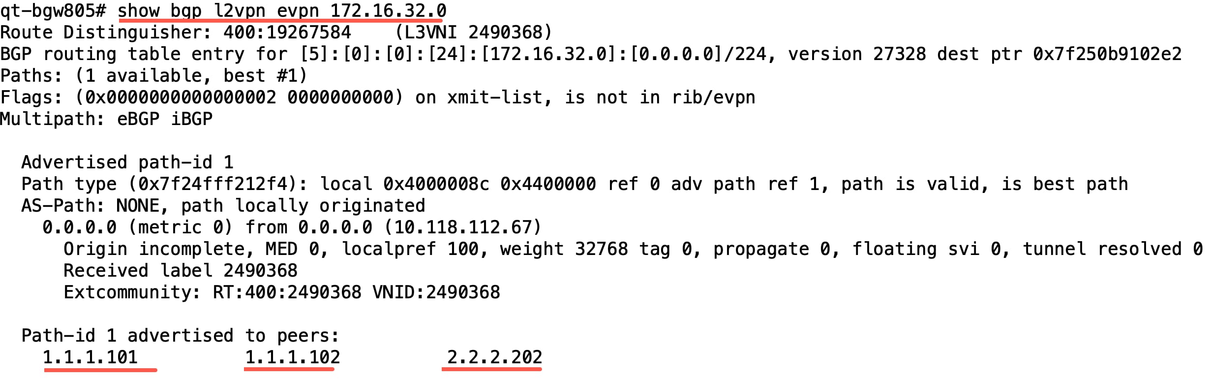
Figure 410. ACI Site 1 Border Gateway receives EVPN Route Type 5 from Site 2 Border Gateway.
In the figure above, 5.5.5.105 is Site 2 Border Gateway loopback IP. The value 60001 represents the normalized L3 VNI of VRF share. After route leak is configured on Site 1, the route 172.16.32.0/24 is leaked to VRF vrf1.
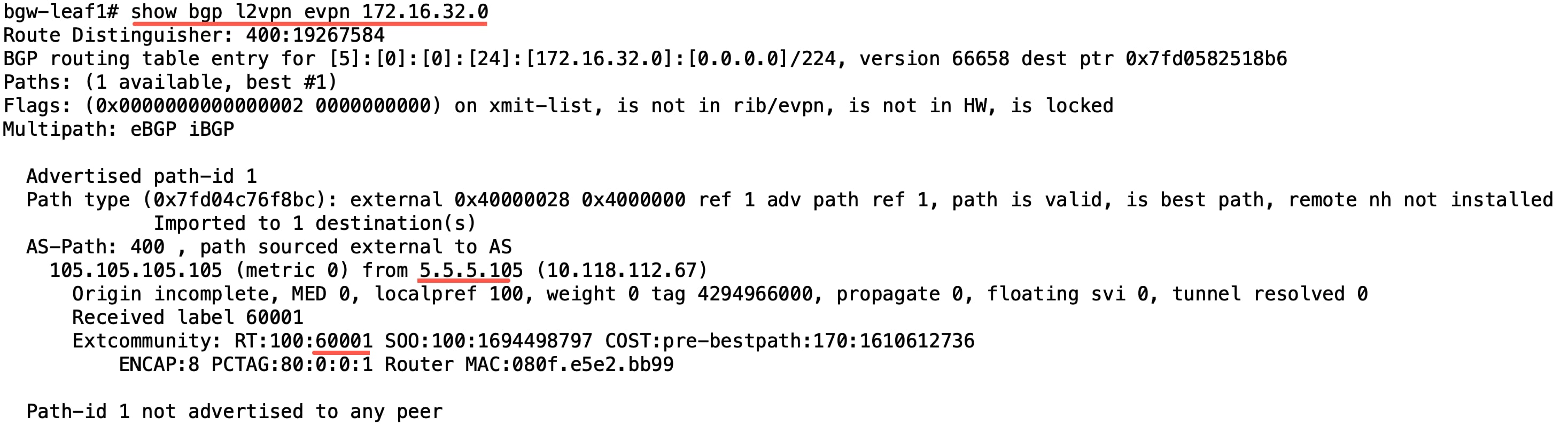
Figure 411. ACI Site 1 Border Gateway VRF vrf1 route table
The route 172.16.32.0/24 is then advertised to Spine trough BGP VPNv4 and later it is reflected to compute leaf leaf1.

Figure 412. ACI Site 1 Compute Leaf VRF vrf1 route table
Let’s verify how the endpoint route 172.16.32.201/32 is imported into VRF vrf1 on the Site 1 Border Gateway. As mentioned above, host route 172.16.32.201/32 is advertised from Site 2 Border Gateway to Site 1 Border Gateway. In vsh mode, on ACI Site 2 Border Gateway:
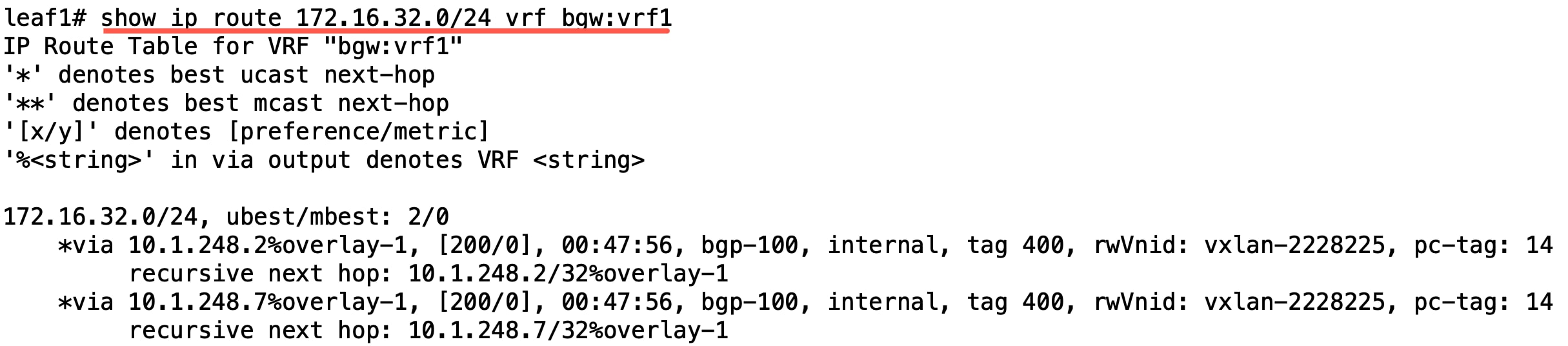
Figure 413. ACI Site 2 Border Gateway advertises EVPN Route Type 2
ACI Site 1 Border Gateways receive EVPN Type 2 route 172.16.32.201 from Site 2 Border Gateway. In vsh mode, Site 1 first Border Gateway:
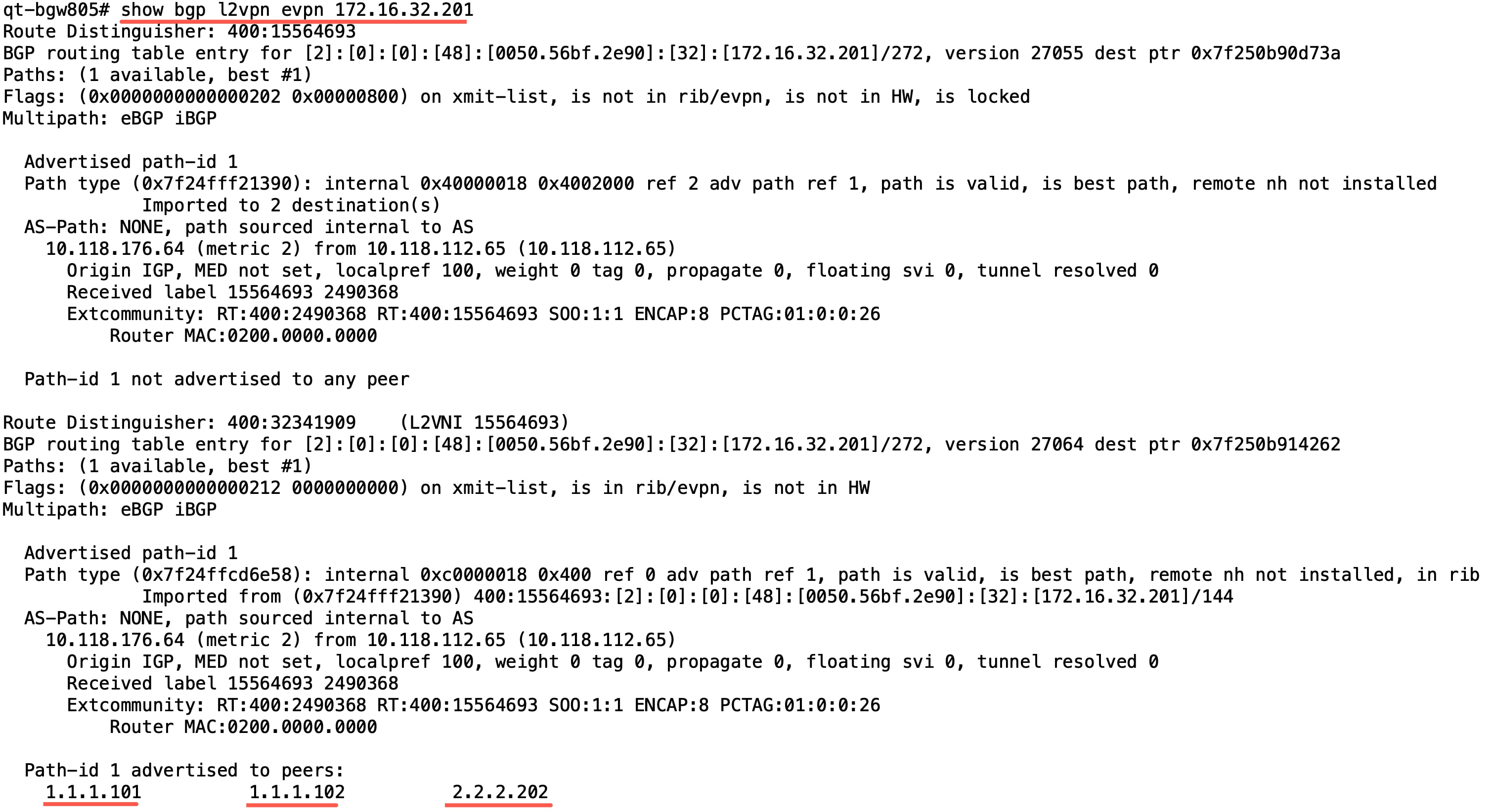
Figure 414. ACI Site 1 Border Gateway receives EVPN Route Type 2 for 172.16.31.201
In the figure above, 5.5.5.105 is Site 2 Border Gateway loopback IP. The value 60001 represents the normalized L3 VNI of VRF share.
Since Site 1 has route leak configuration with Internal Prefixes 172.16.32.0/24 and “Less than or Equal (Prefix)” set to 32, the host route 172.16.32.201 is leaked from VRF share to VRF vrf1 with proper pcTag. In exec mode on Site 1 Border Gateway, in VRF vrf1, Border Gateway has route with pcTag of 31 which is local pcTag of ESG share2 on Site1 itself.
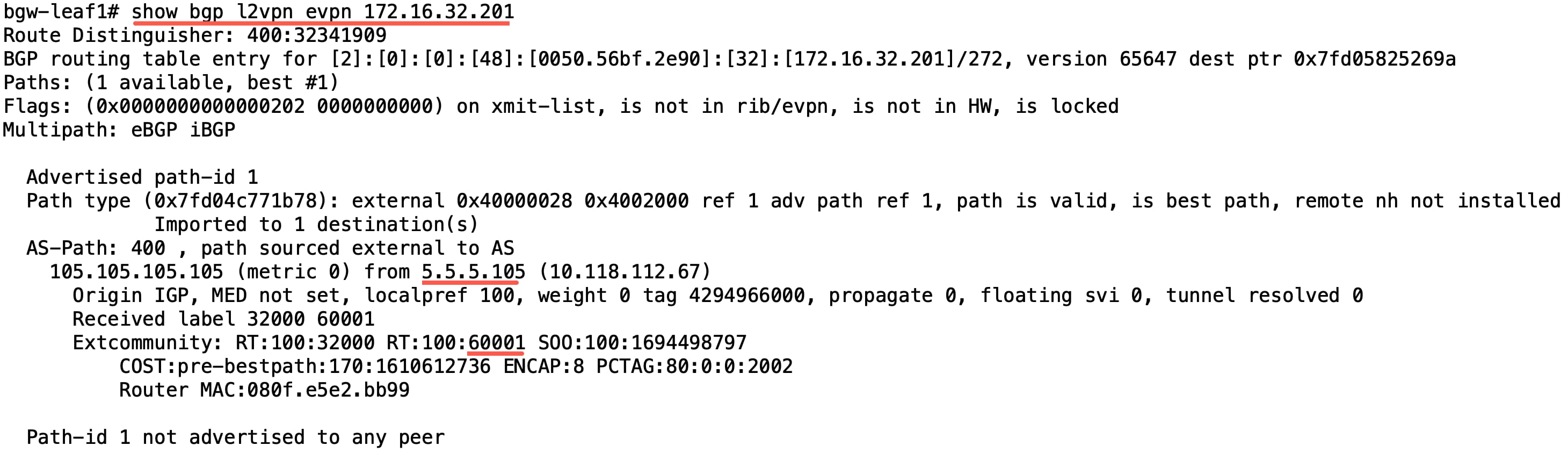
Figure 415. ACI Site 1 Border Gateway receives host route with proper local pcTag
Here shown the local pcTag of ESG share2 in Site1 for reference:

Figure 416. ACI Site 1 ESG share2 local pcTag
For easy of verification, it is shown here the route leak configuration on Site 1.
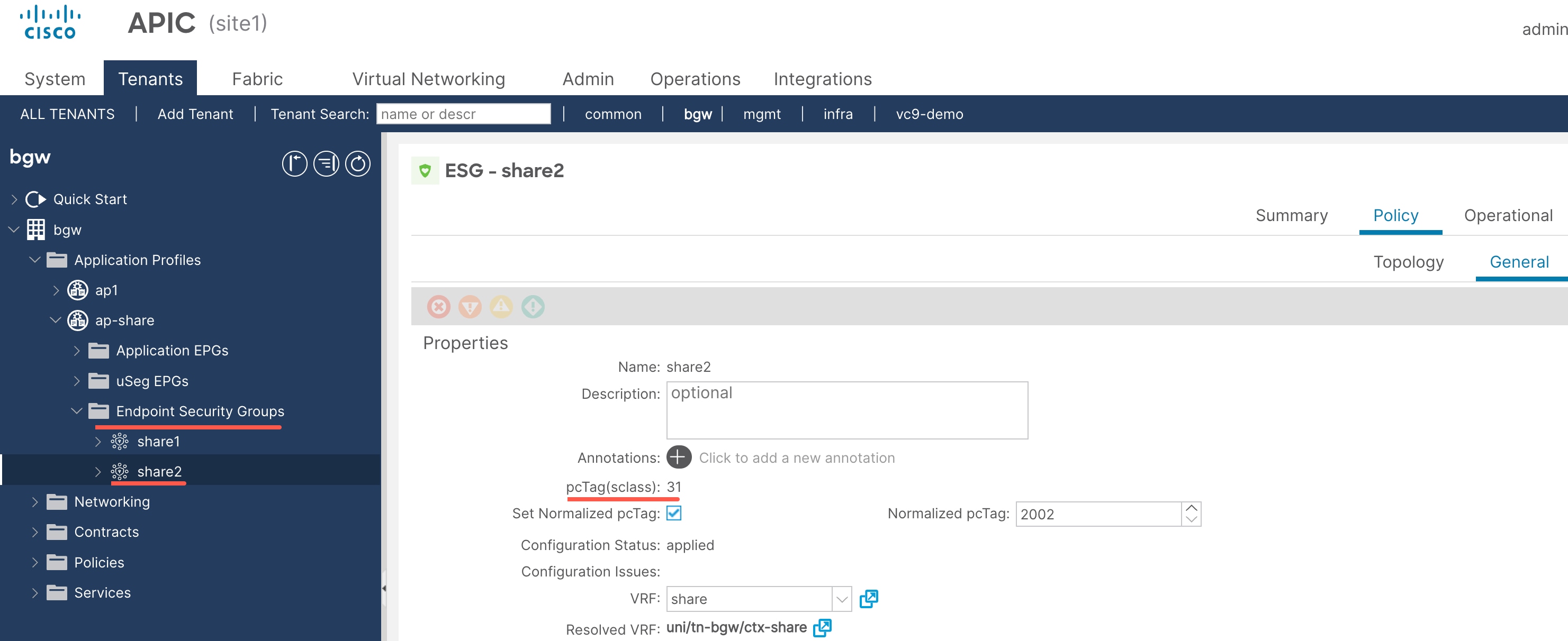
Figure 417. ACI Site 1 route leak from VRF share to VRF vrf1
Note that the value 32 in “Less Than or Equal(Prefix)” is critical, without it the host route is still leaked to VRF vrf1 however the pcTag is wrong causing data plane broken between EP-5 and EP-6.
Failure scenario (Leaked prefix does not cover host route): Let do quick verification by set “Less Than or Equal(Prefix)” to 32 or unspecified.
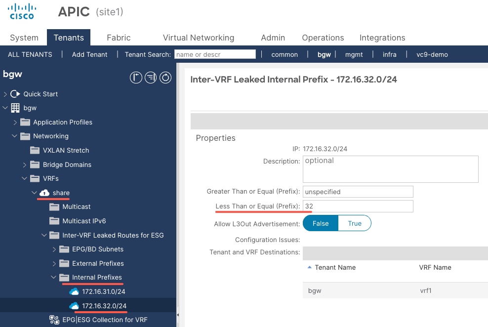
Figure 418. ACI Site 1 leak route “Less Than or Equal(Prefix)” set to 31
As shown in the figure below, the Site 1 Border Gateway does not have the endpoint (host route) in VRF vrf1, so it assigns pcTag 11 to the host route. pcTag 11 is a reserved tag that indicates the endpoint is not learned in the control plane. This signals the compute leaf in the same site to drop packets originating from that endpoint.
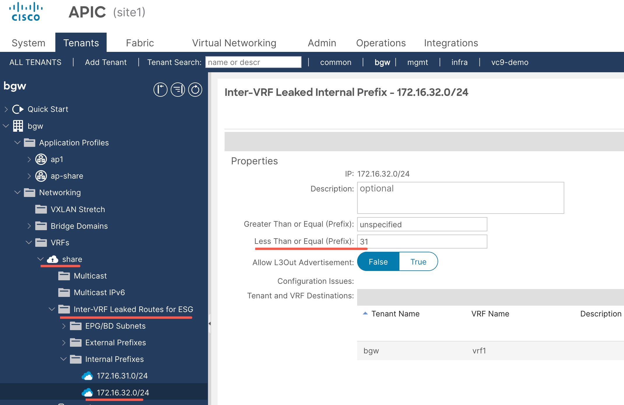
Figure 419. ACI Site 1 Border Gateway receives only subnet route and set endpoint with pcTag 11
Following the same procedure, it is verified that in VRF share, ACI Site 2 Border Gateway learns host route 192.168.50.11 with proper pcTag and compute leaf learns route to 192.168.50.0/24. ACI Site 2 compute leaf VRF share route table.

Figure 420. ACI Site 2 compute leaf VRF share route table
ACI Site 2 Border Gateway learns host route and sets proper local pcTag.

Figure 421. ACI Site 2 Border Gateway learns host route in VRF share

Figure 422. ACI Site 2 ESG esg50 local pcTag
Data Plane Verification
The figure below illustrates the policy enforcement location and VNI translation behavior for traffic from 192.168.50.11 (VRF vrf1) in ACI Site 1 to 172.16.32.201 (VRF share) in ACI Site 2. In the case of inter-VRF communication, ingress compute leaf performs “VRF switch” also known as VRF re-write, from the source VRF to the destination VRF using the local source and destination VNI numbers, since the compute leaf is not aware of the normalized VNI.
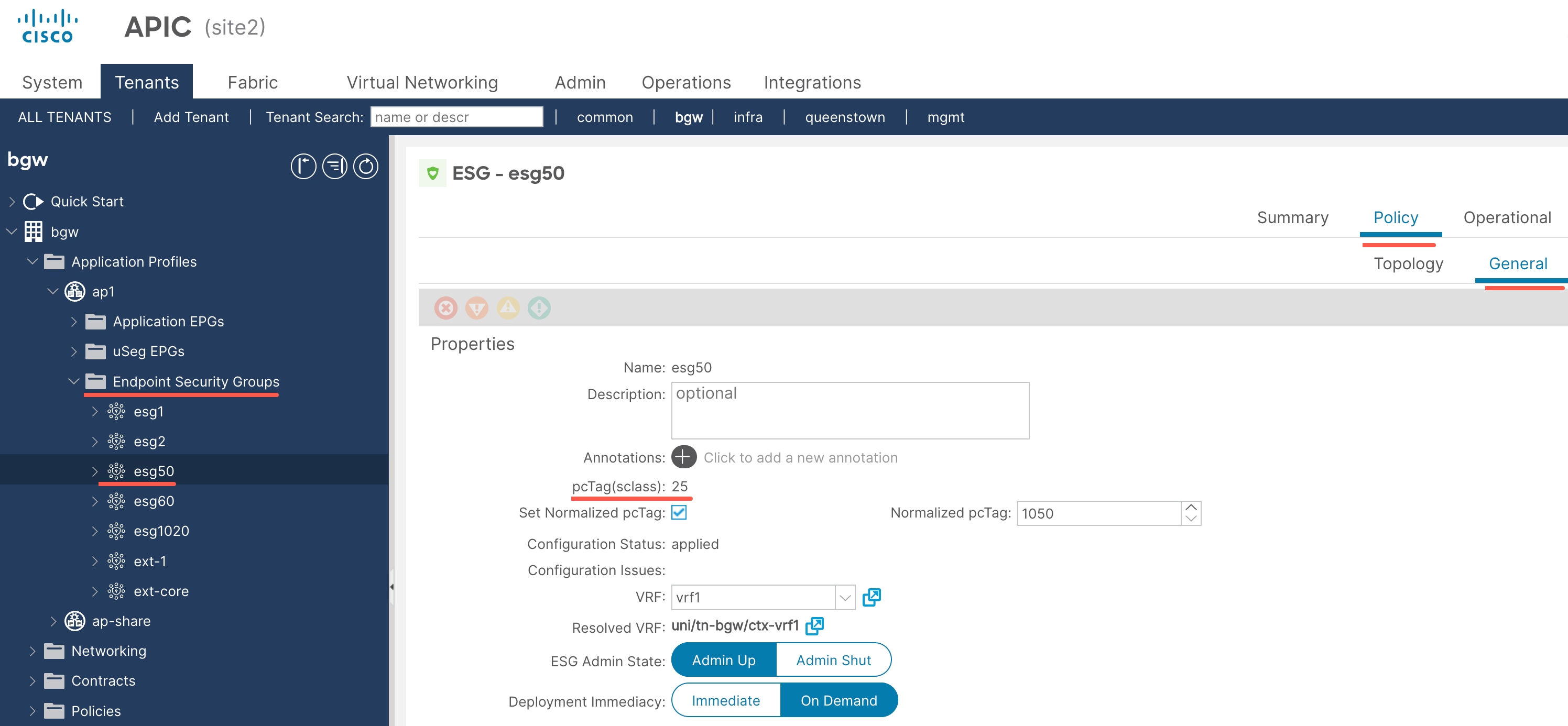
Figure 423. ACI Site 1 VRF vrf1 to ACI Site 2 VRF share, ingress leaf performs VRF switch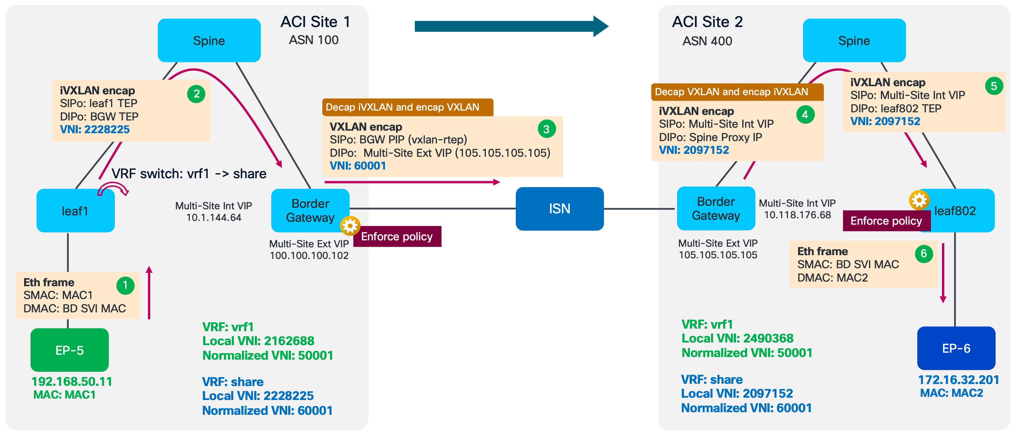
Figure 424. ACI Site 2 VRF share to ACI Site 1 VRF vrf1, ingress leaf performs VRF switch
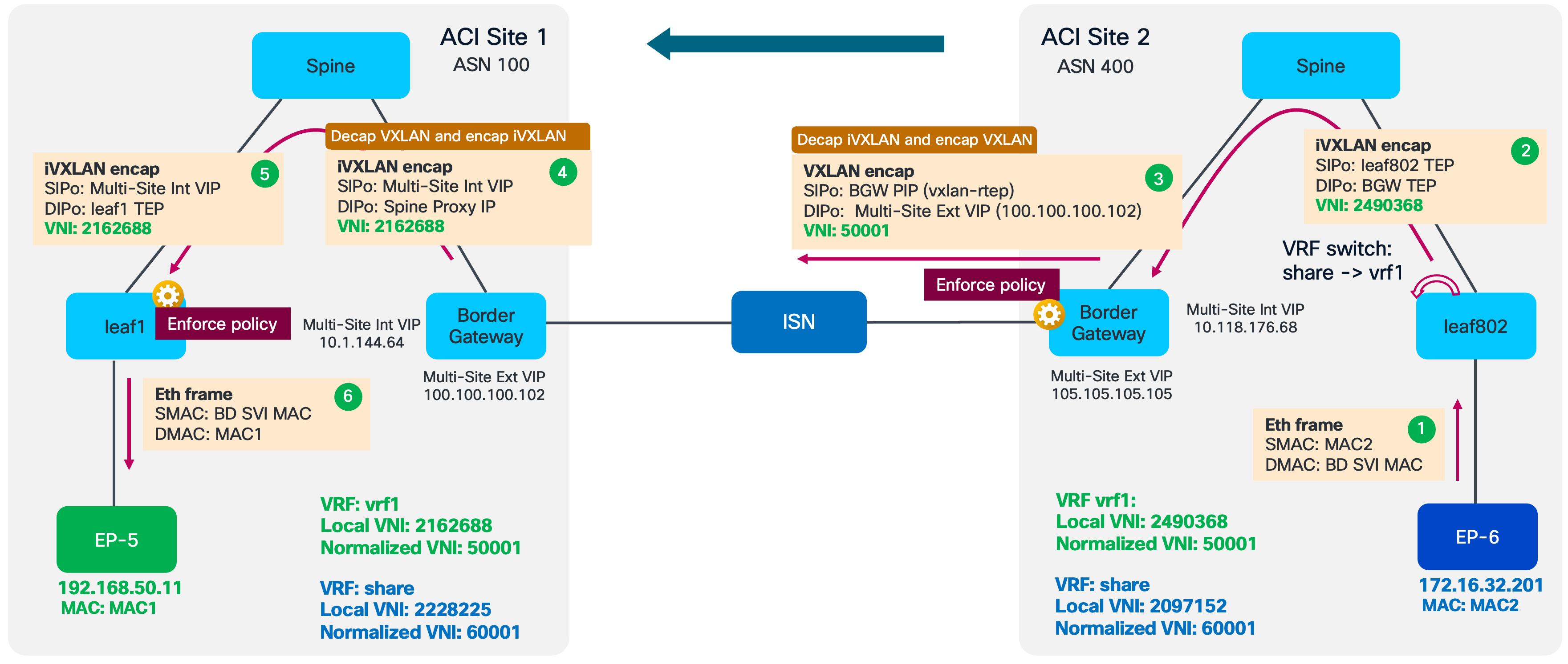
Figure 425. Data plane Inter-VRF Communication (Shared Services) with Non-stretched BDs
Ping from 192.168.50.11 in ACI Site 1 to 172.16.32.201 in ACI Site 2. The packet capture of the ICMP request from EP-5 to EP-6 confirms that the Layer 3 (VRF) Normalized VNI of the destination VRF (VRF share) is used in the VXLAN header for inter-site data plane forwarding.
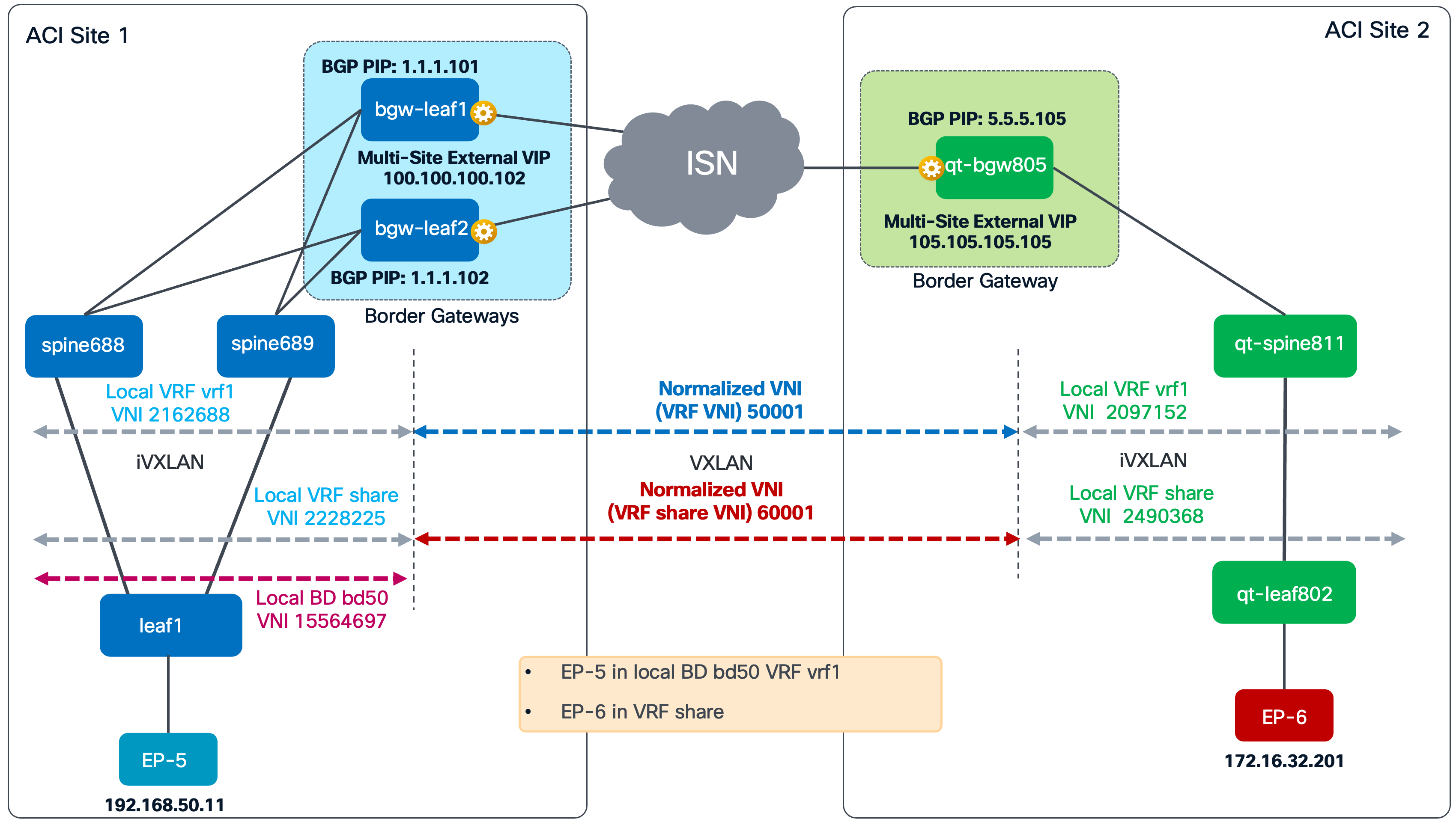
Figure 426. ICMP request from EP-5 (192.168.50.11) to EP-6 (172.16.32.201)
The packet capture of the ICMP reply from EP-6 to EP-5 confirms that the Layer 3 (VRF) Normalized VNI of the destination VRF (VRF vrf1) is used in the VXLAN header for inter-site data plane forwarding.
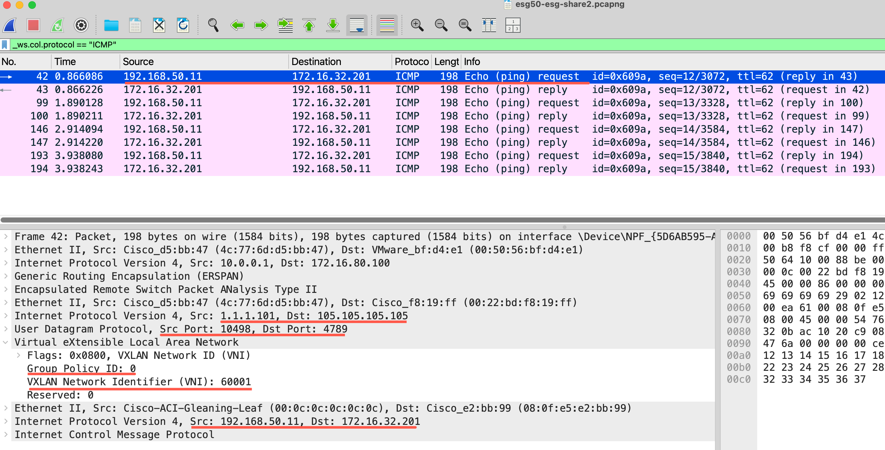
Figure 427. ICMP reply from EP-6 (172.16.32.201) to EP-5 (192.168.50.11)
The figure below illustrates the policy enforcement location for traffic from 192.168.50.11 (endpoint in ESG esg50 in VRF vrf1) in ACI Site 1 to 172.16.32.201 (endpoint in ESG share2 in VRF share) in ACI Site 2.
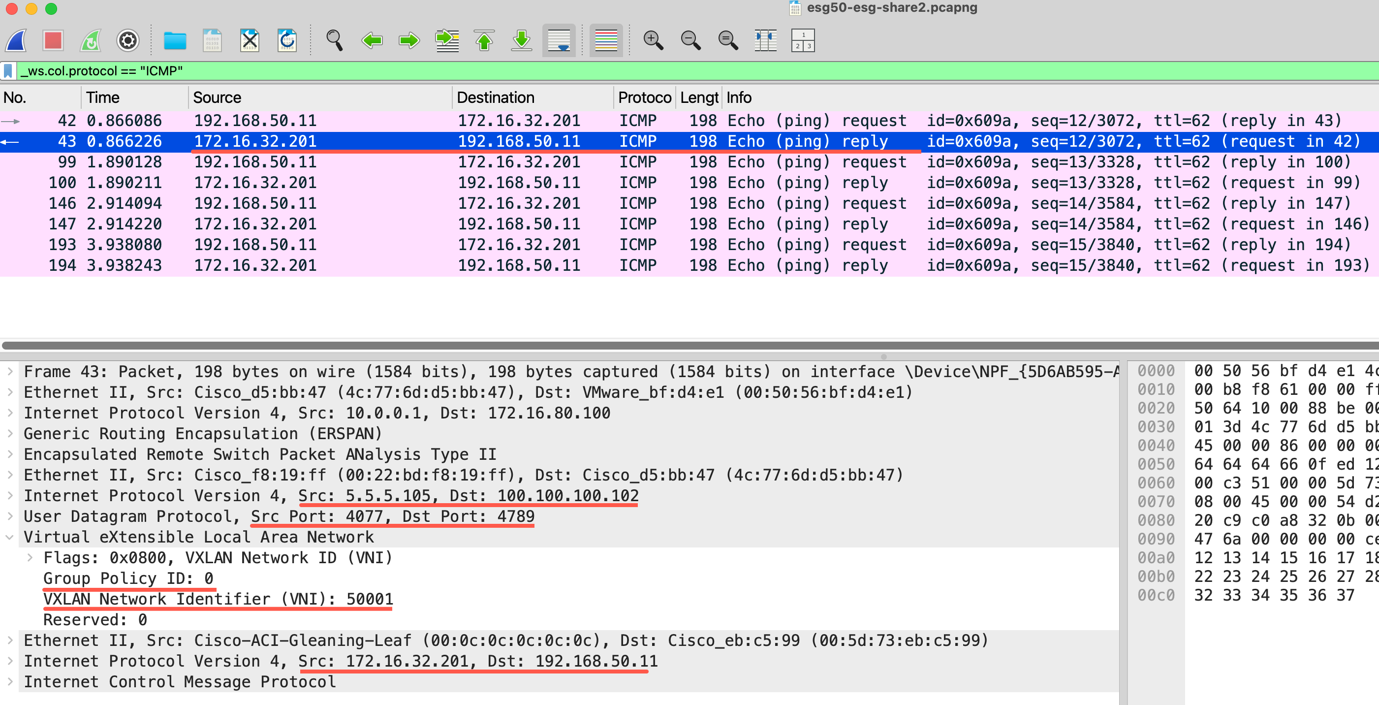
Figure 428. Policy enforcement VRF vrf1 to VRF share, from ACI Site 1 to ACI Site 2
As outlined in the Data Plane verification, the compute leaf at the source site (Site 1 in this flow) performs a VRF switch from VRF vrf1 to VRF share. Following this VRF switch, the policy enforcement aligns with the behavior described in Use Case 4: Inter-Subnet Communication with Non-stretched BDs Multiple ESGs. Specifically, for traffic flowing from ACI Site 1 to ACI Site 2 (from VRF vrf1 to VRF share):
● ACI Site 1 Border Gateway applies policy in VRF share
● ACI Site 2 Compute Leaf applies policy in VRF share
The figure below illustrates the policy enforcement location for traffic from 172.16.32.201 (endpoint in ESG share2 in VRF share) in ACI Site 2 to 192.168.50.11 (endpoint in ESG esg50 in VRF vrf1) in ACI Site 1.
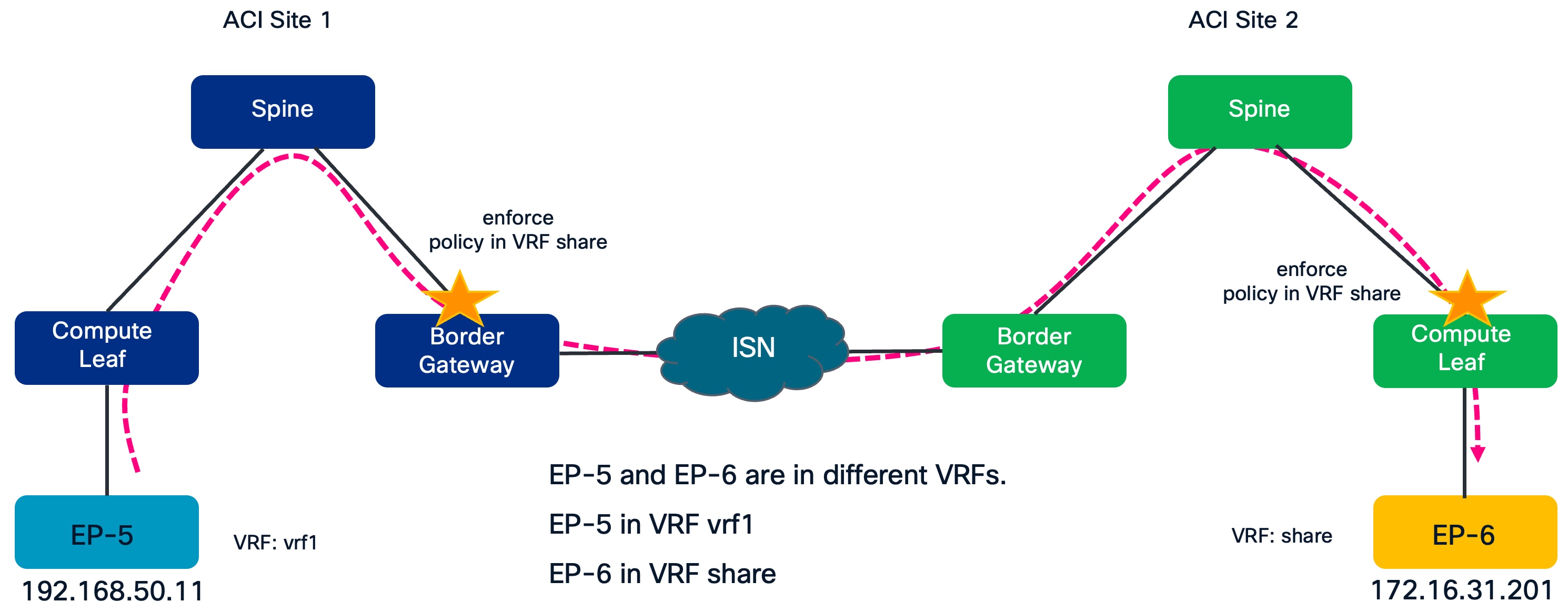
Figure 429. Policy enforcement VRF share to VRF vrf1, from ACI Site 2 to ACI Site 1
Similarly, the compute leaf at the source site (Site 2 in this flow) performs a VRF switch from VRF share to VRF vrf1. Following this VRF switch, the policy enforcement aligns with the behavior described in Use Case 4: Inter-Subnet Communication with Non-stretched BDs Multiple ESGs. Specifically, for traffic flowing from ACI Site 2 to ACI Site 1 (from VRF share to VRF vrf1):
● ACI Site 2 Border Gateway applies policy in VRF vrf1
● ACI Site 1 Compute Leaf applies policy in VRF vrf1
Use Case 11: Inter-VRF Communication (Shared Services) with Shared L3Out
This section covers an inter-VRF communication use case with an L3Out where the source and the destination reside in different VRFs similar to the previous use case. A shared L3Out and its ESG does not have to be in the same tenant with the ESG for endpoints.
The figure below illustrates an example used in this section. VRFs, BDs and ESGs are stretched across sites, and the L3Out is local to ACI Site 1. Although this example shows stretched VRFs, Bridge Domains, and ESGs, only the VRF must be stretched. The BD and ESG may remain local to each site. A Contract is configured between ESG ext-1 in VRF vrf1 and ESG share1 in VRF share. When an endpoint in ESG share1 in ACI Site2 communicate with an external endpoint in ESG ext-1 (100.64.1.0/24), it will go through the L3Out in ACI Site 1.
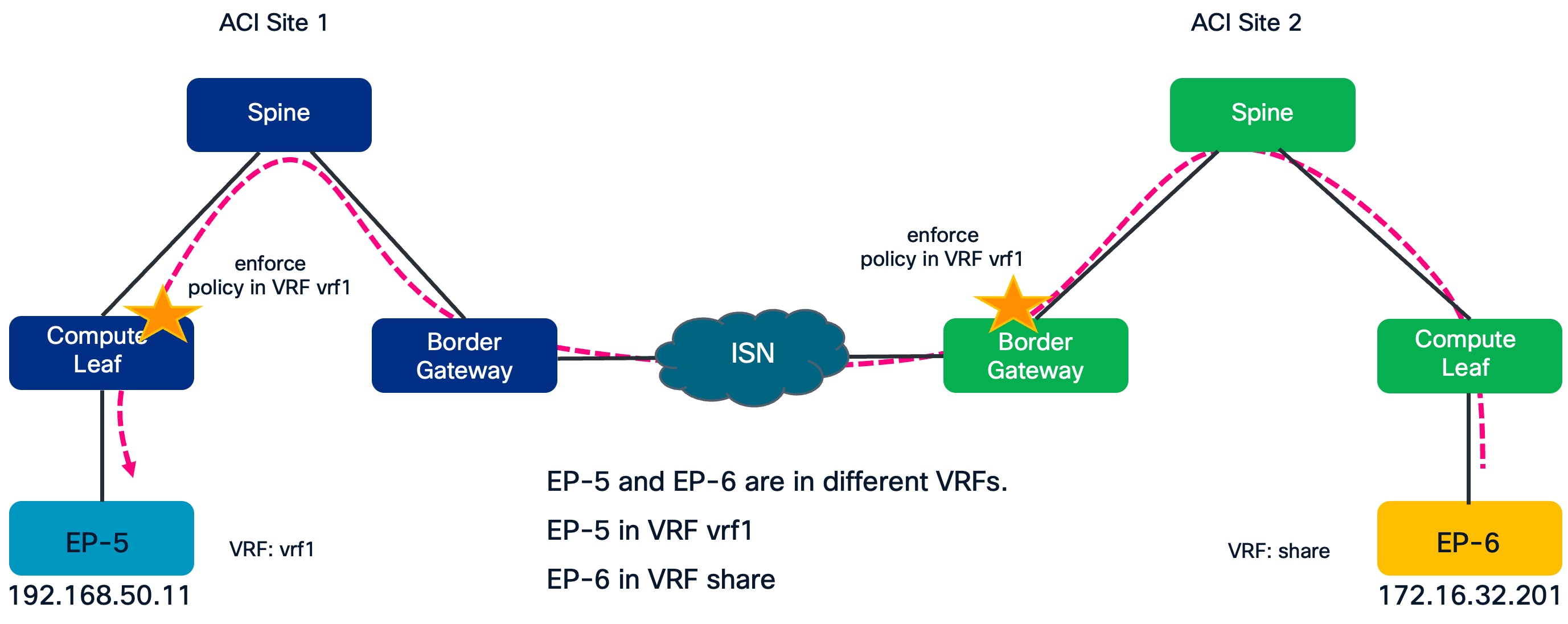
Figure 430. Shared L3Out across ACI Sites
The configuration steps are following:
● Create VRF share, BD bd-share1, stretch the VRF and the BD.
● Create ESG share1 with the normalized pcTag.
● Leak ACI Site 1 VRF vrf1 external prefix to VRF share.
● Leak BD bd-share1 subnet in VRF share to ACI Site 1 VRF vrf1 L3Out.
● Apply a tenant scope contract between ESG esg1 and ESG ext-1.
● Enabled “Shared” flag under ESG External Subnet Selector (for external subnet 100.64.1.0/24) in ACI Site 1
Since the first two steps are identical with the previous use case, this section covers the last four steps.
The following figure summarizes the leaked subnet information between VRF vrf1 and VRF share. In this example, the following subnets need to be leaked:
● 100.64.1.0/24 learnt via the L3Out in VRF vrf1 needs to be leaked to VRF share.
● 172.16.31.0/24 in bridge domain bd-share of VRF share must be leaked to VRF vrf1.
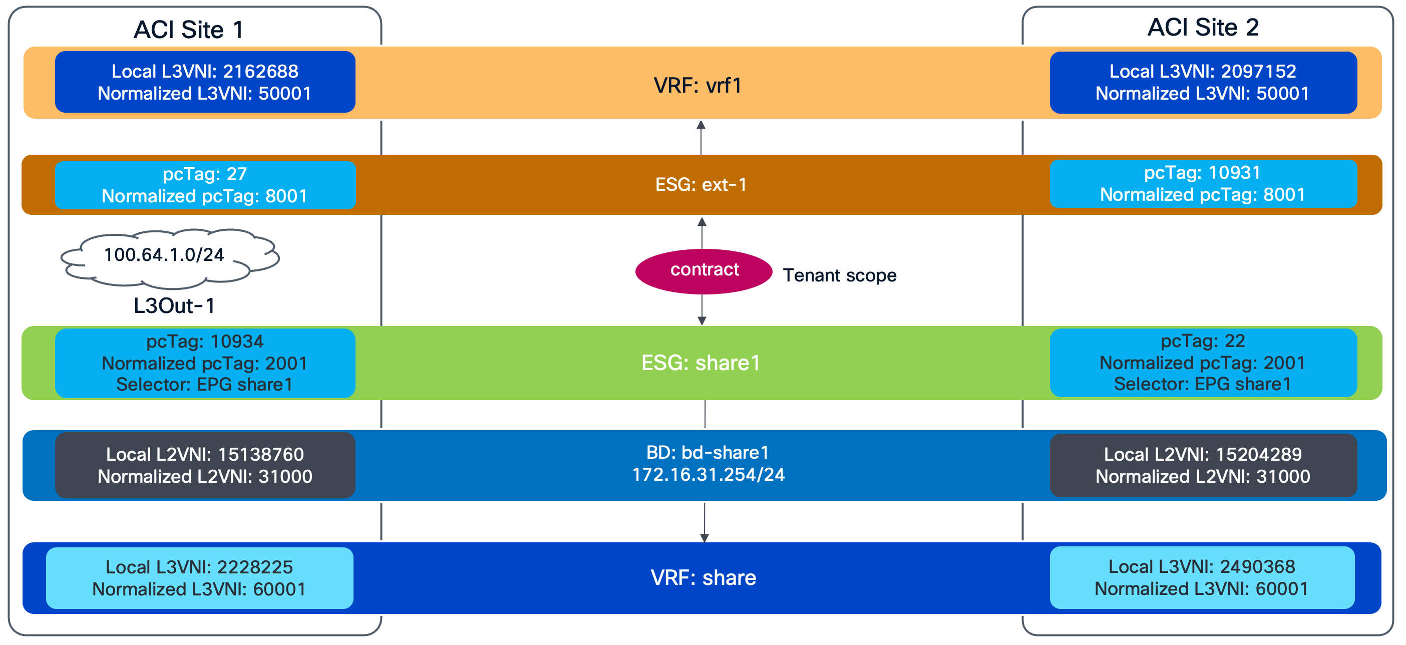
Figure 431. Leak routes across VRF
Advertise External Route from L3Out to Remote VRF
This section covers how to leak an external prefix to another VRF. At ACI Site 1, navigate to Networking -> VRFs -> vrf1 -> Inter-VRF Leaked Routes for ESG. Right click and choose “Create Leaked External Prefix”. And follow the wizard to specify the prefix and the destination VRF where the prefix needs to be leaked.
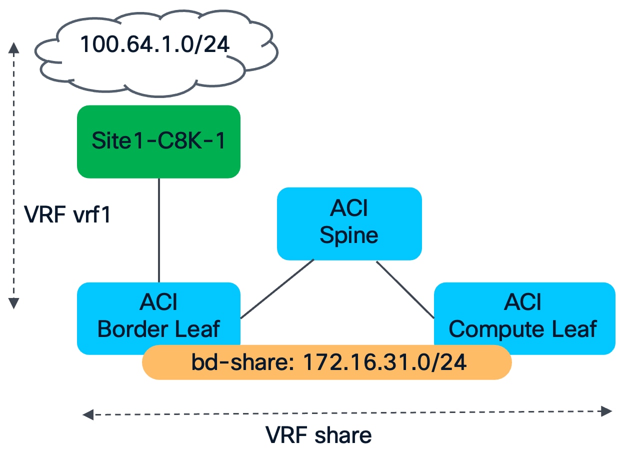
Figure 432. Create Leaked External Prefix
Enter 100.64.1.0/24 in the IP field, then click “+” button.
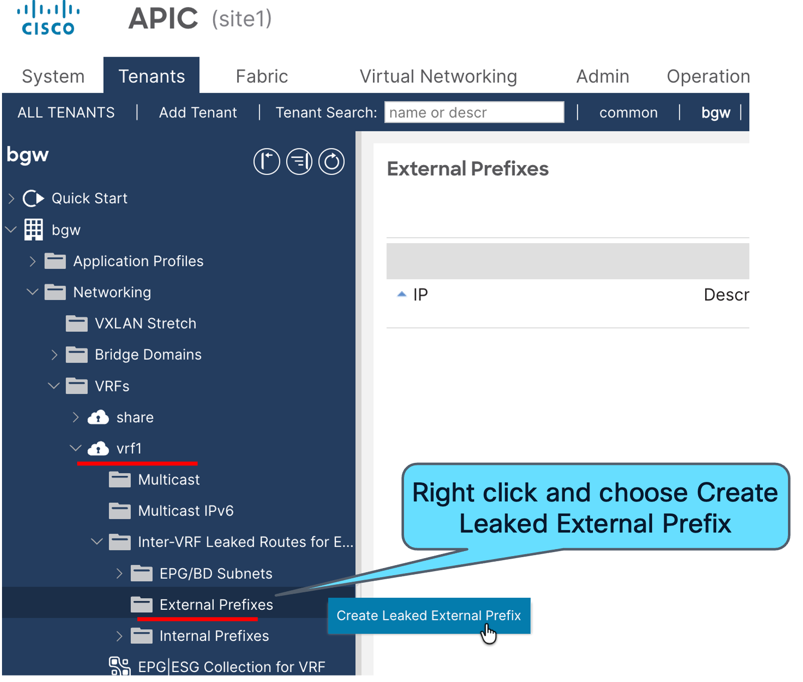
Figure 433. Define 100.64.1.0/24 as leaked external prefix
Choose “bgw” from the Tenant drop-down list, choose “share” from VRF drop-down list then click OK.
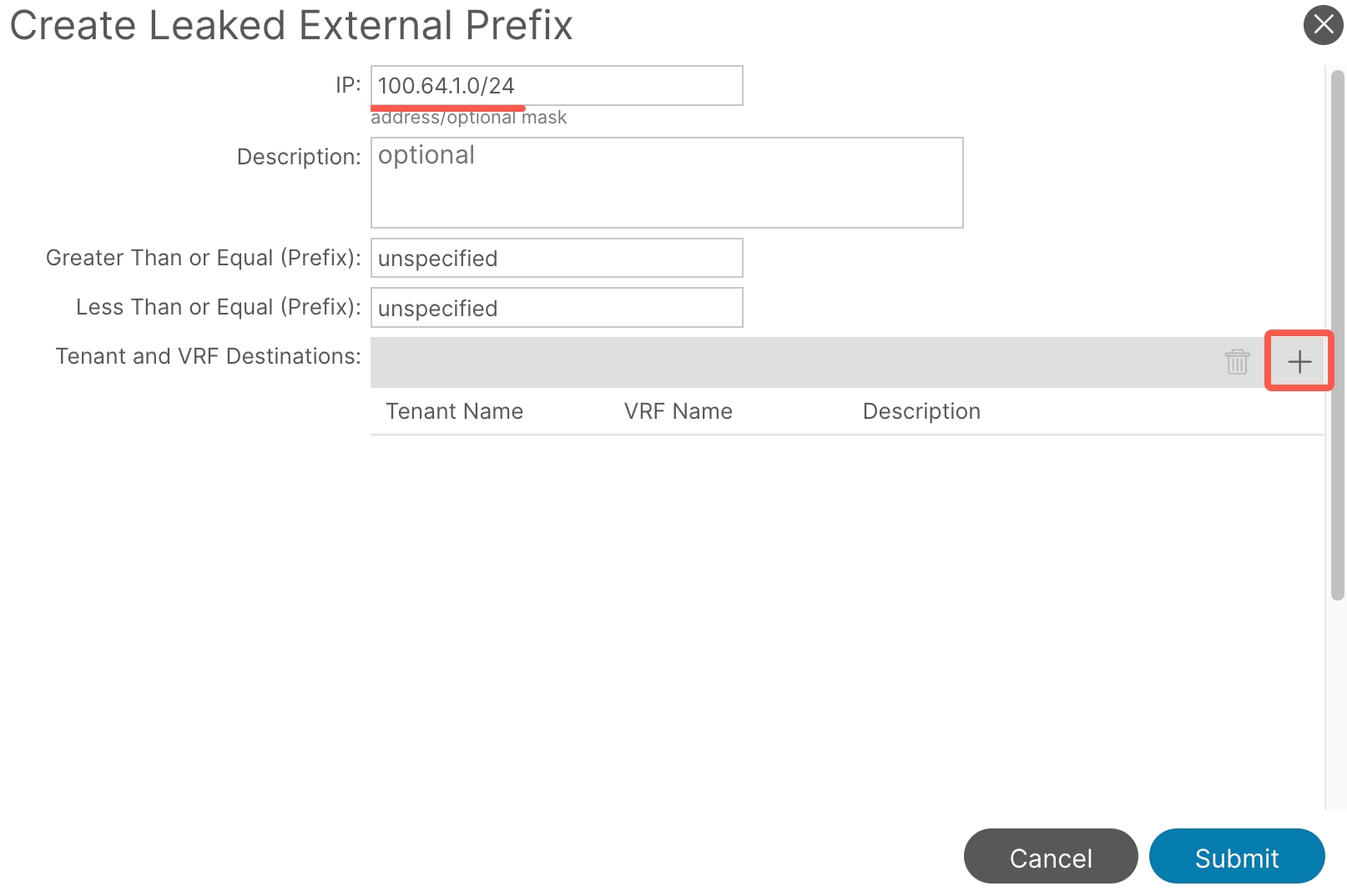
Figure 434. Choose VRF share as destination VRF
Click Submit to finish.
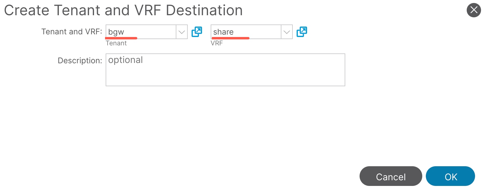
Figure 435. Leak External Prefix to destination VRF completion
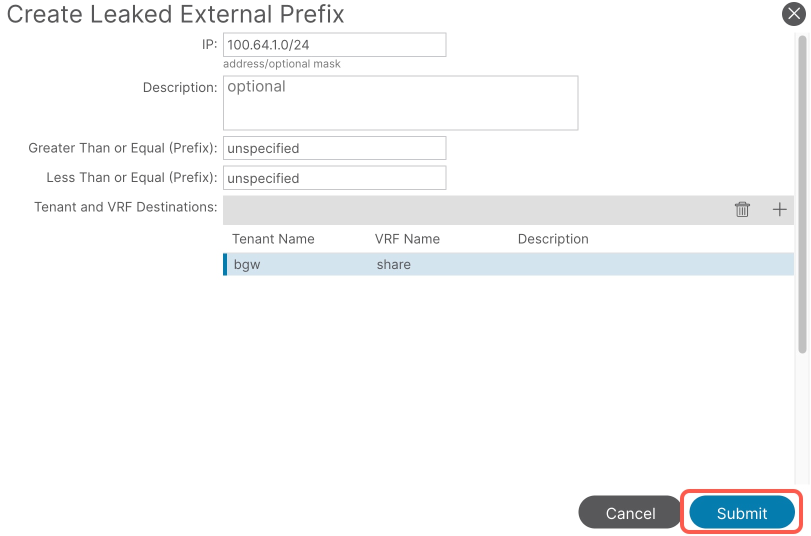
Figure 436. Leak external prefix to different VRF completion
Advertise Internal Bridge Domain Subnet to L3Out Across VRF
This section covers how to leak an internal subnet to an external network in another VRF.
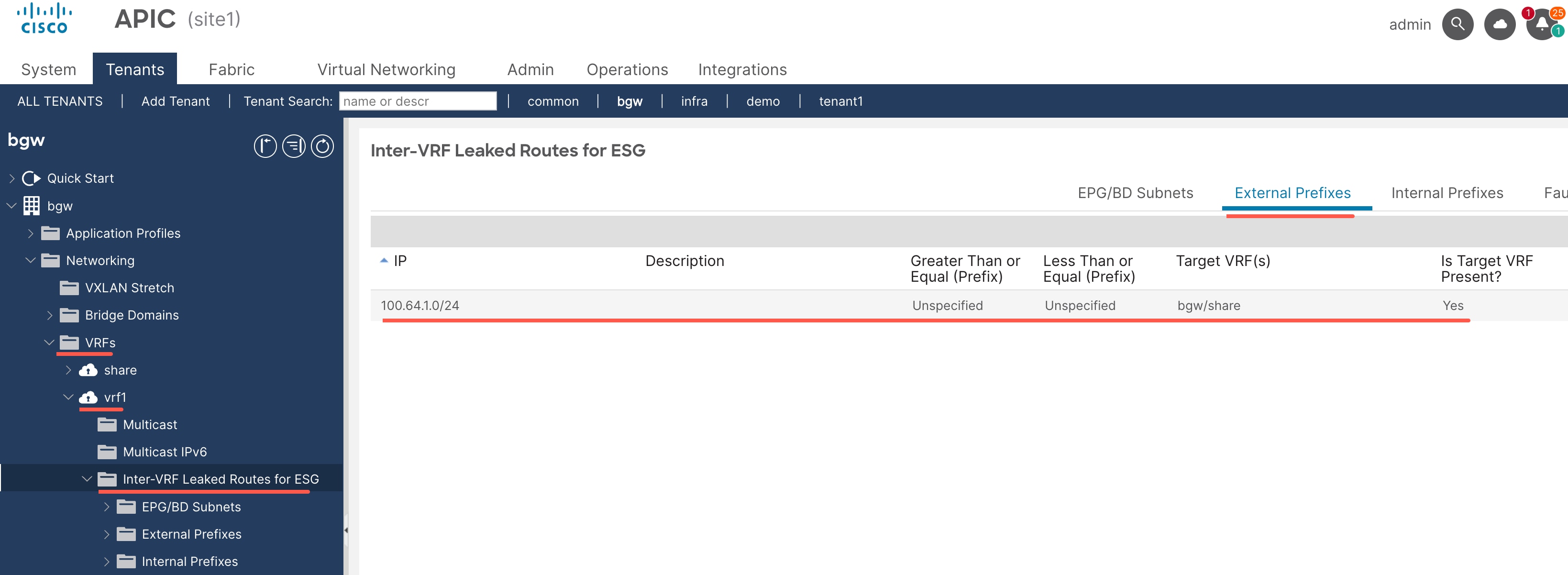
Figure 437. Advertise 172.16.31.0/24 to ACI Site 1 L3Out in VRF vrf1
At ACI Site 1, make sure the subnet 172.16.31.0/24 is leaked from VRF share to VRF vrf1 using Internal Prefixes route leak.
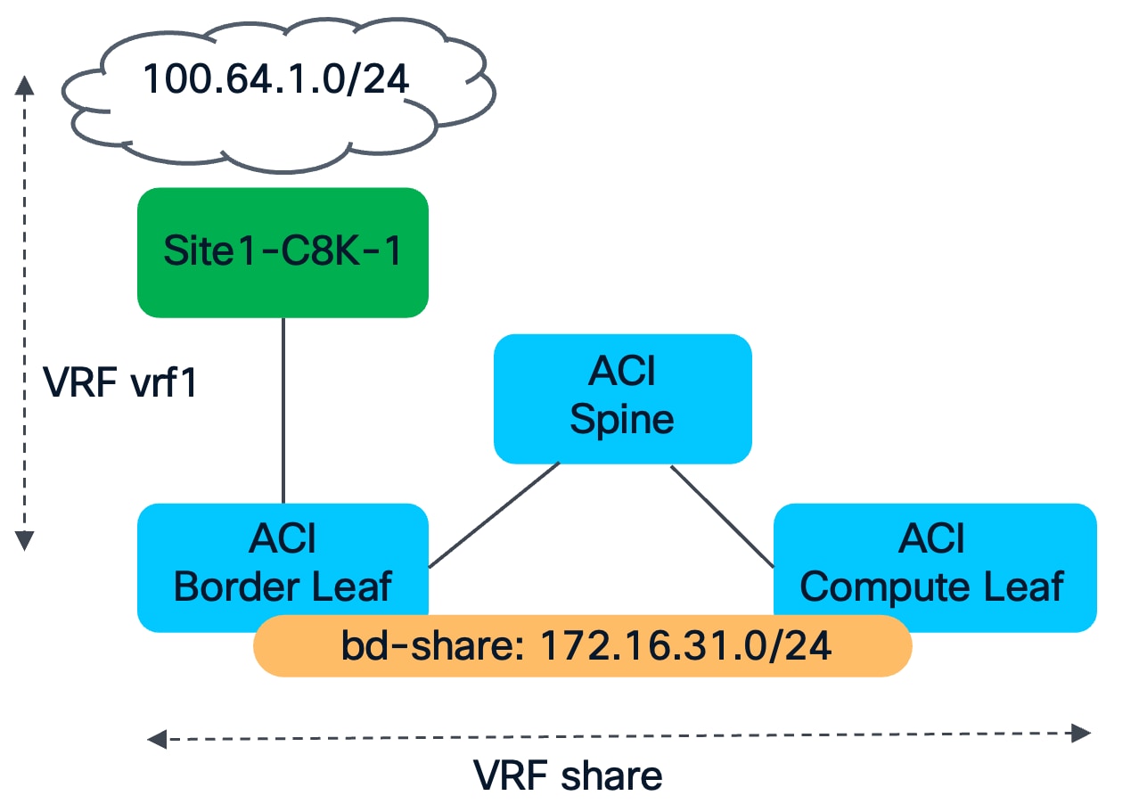
Figure 438. ACI Site 1 Internal Prefixes leak 172.16.31.0/24 to VRF vrf1
A route profile configuration is required at the external EPG to export the internal prefix to L3Out. In this example, the route profile that has a match prefix rule for 172.16.31.0/24 is required on the external EPG under the L3Out in VRF vrf1. After this step, subnet 172.16.31.0/24 is advertised from VRF share to the external router in VRF vrf1 in ACI Site 1.
It is important to note that a given external EPG supports only one Route Control Profile per direction. In Use Case 7: Transit Routing Across ACI Sites, the route map transit-100-68-1 has already been applied in the export direction under the Route Control Profile associated with the External EPG bgp-ext-epg. Therefore, applying a new export route map in this scenario would replace the existing association and cause transit-100-68-1 to be detached.
Although this use case uses a different route-map named 172-vrf-share, the existing route-map transit-100-68-1 can be reused by adding an additional context to the existing route map.
The following figures show a configuration example for route control profile at the external EPG. Route-map 172-vrf-share is associated to external EPG bgp-ext-epg in ACI Site 1.
Figure 439. Apply route profile export direction
Route-map 172-vrf-share is configured with a match prefix rule for 172.16.31.0/24.
Figure 440. Route-map to match 172.16.31.0/24 subnet
Figure 441. Route Context
Figure 442. Match rule to match 172.16.31.0/24
Create and Apply Tenant Scope Contract
On both ACI Sites, create a tenant scope contract named bgw-shared-l3out, apply this contract between ESG share1 and ESG ext-1.
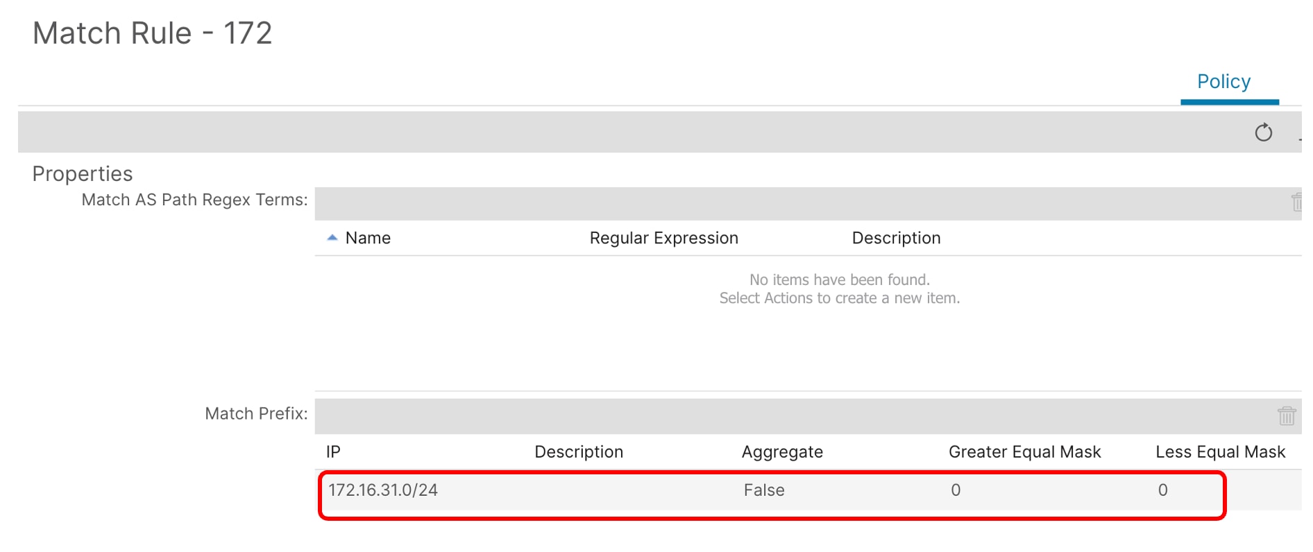
Figure 443. Shared L3Out logical topology
The following screenshots show a contract configuration example.
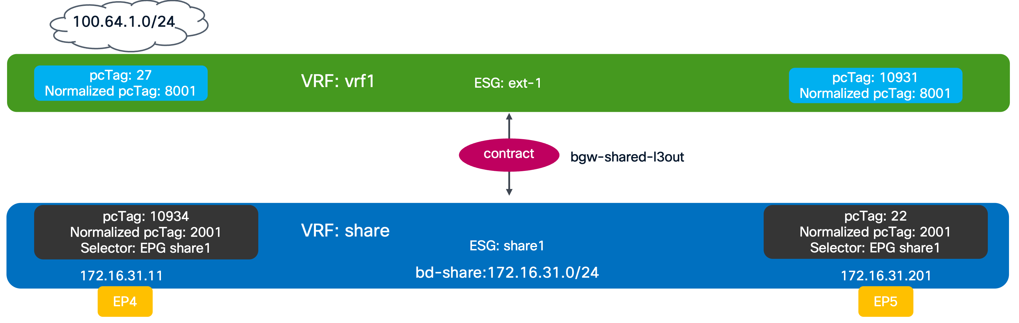
Figure 444. ACI Site 1 tenant-scope contract
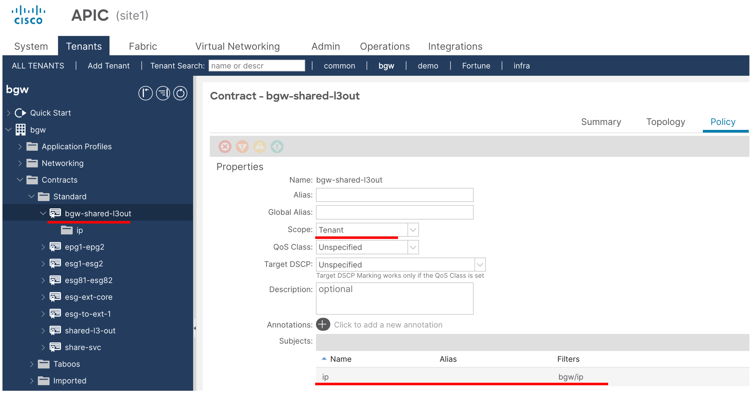
Figure 445. ACI Site 1 ESG share1 contract consumer
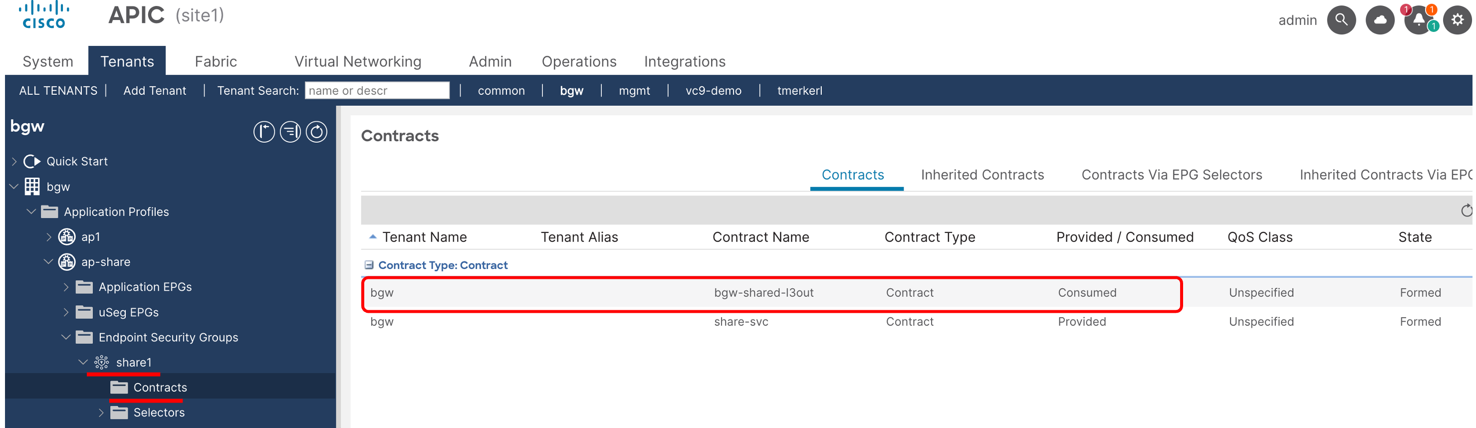
Figure 446. ACI Site 1 ESG ext-1 contract provider
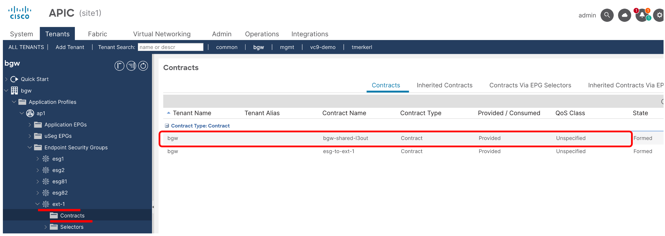
Figure 447. ACI Site 2 tenant-scope contract
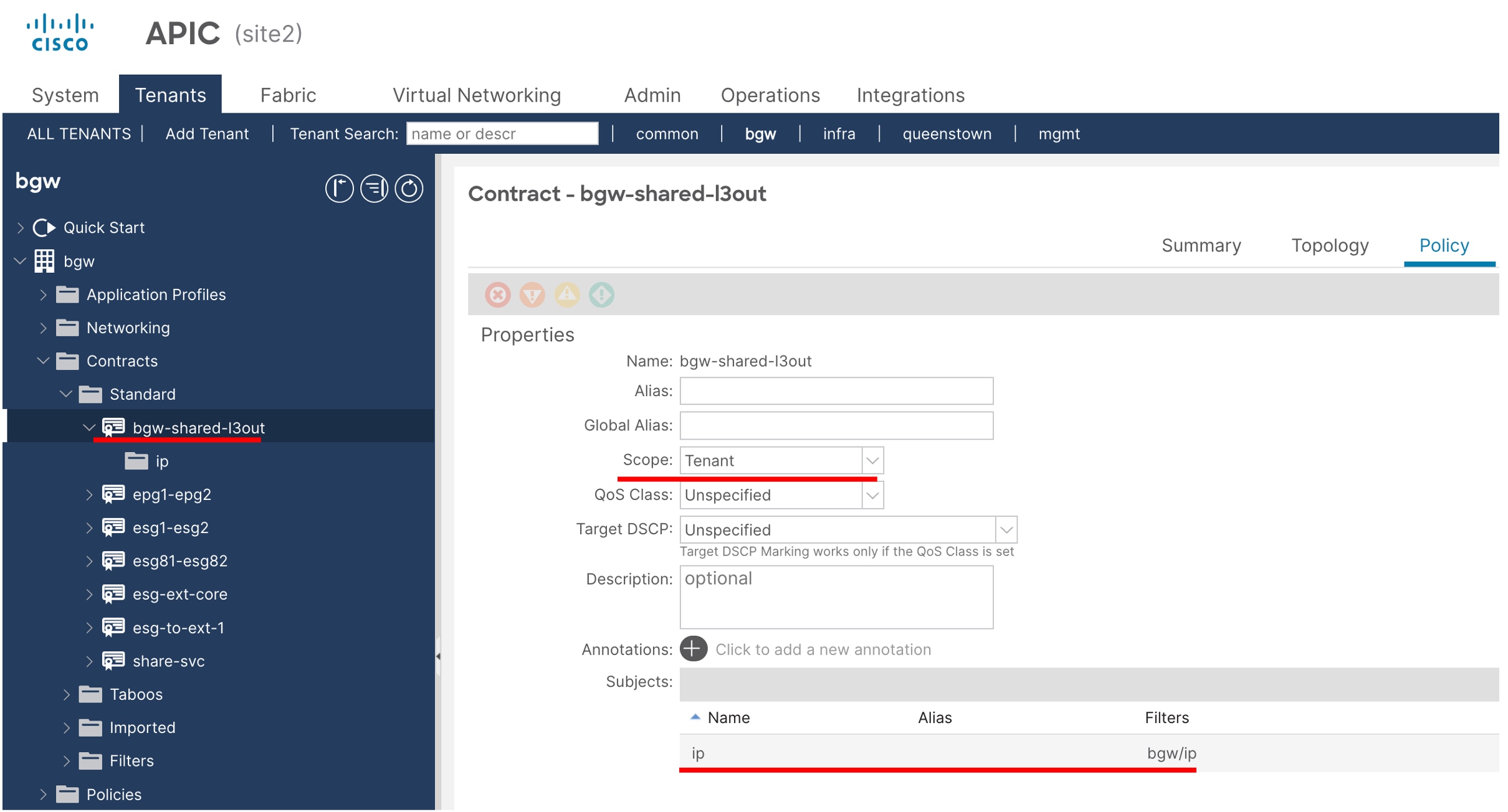
Figure 448. ACI Site 2 ESG share1 contract consumer
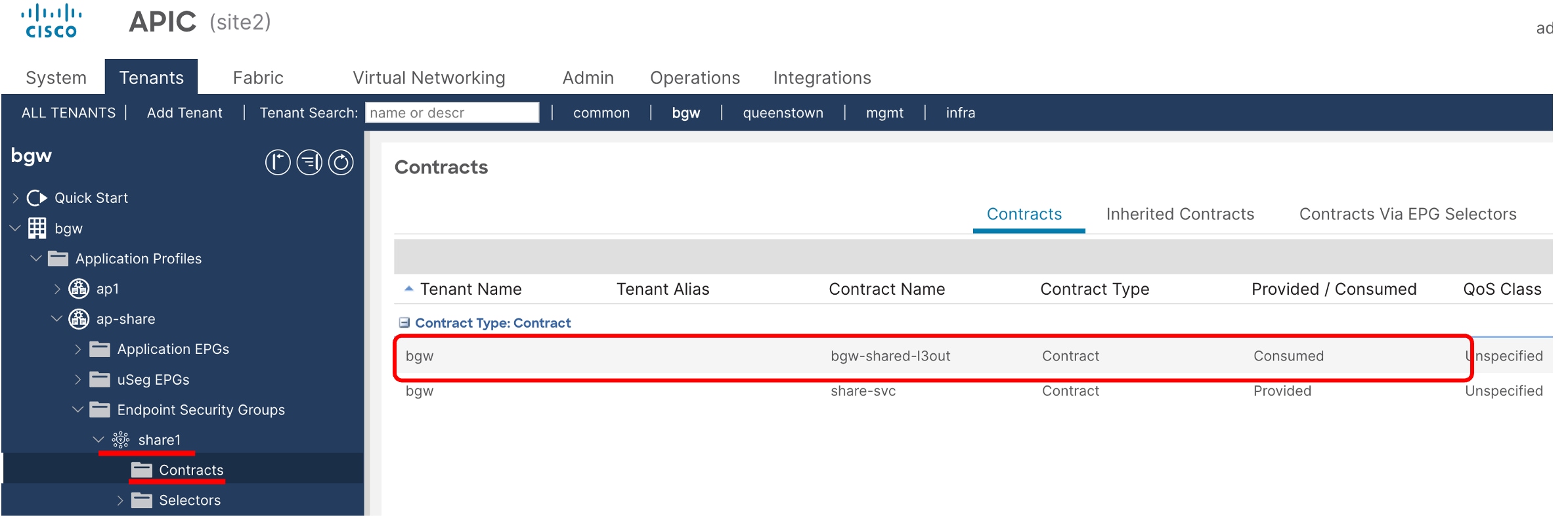
Figure 449. ACI Site 2 ESG ext-1 contract provider
Enable Shared flag in ESG External Subnet Selector
The “Shared” flag needs to be enabled at the external subnet selector for the ESG ext-1 otherwise endpoint in VRF share in ACI Site 1 is not allowed to communication to external endpoint in L3Out in ACI Site 1 even with tenant-scope contract applied. Navigate to ESG ext-1 -> Selectors -> Double-click on External subnet.
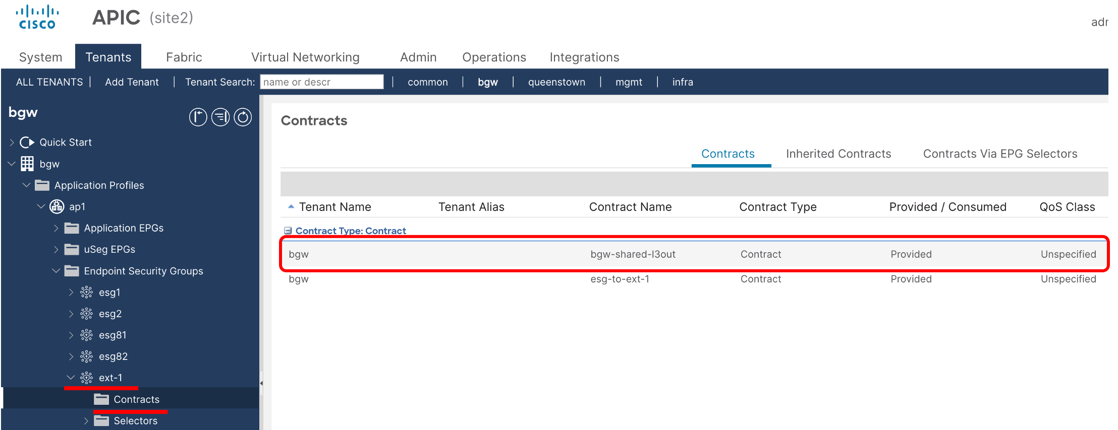
Figure 450. Enable shared flag in external subnet
Once the External subnet setting window open, check Shared and click Submit.
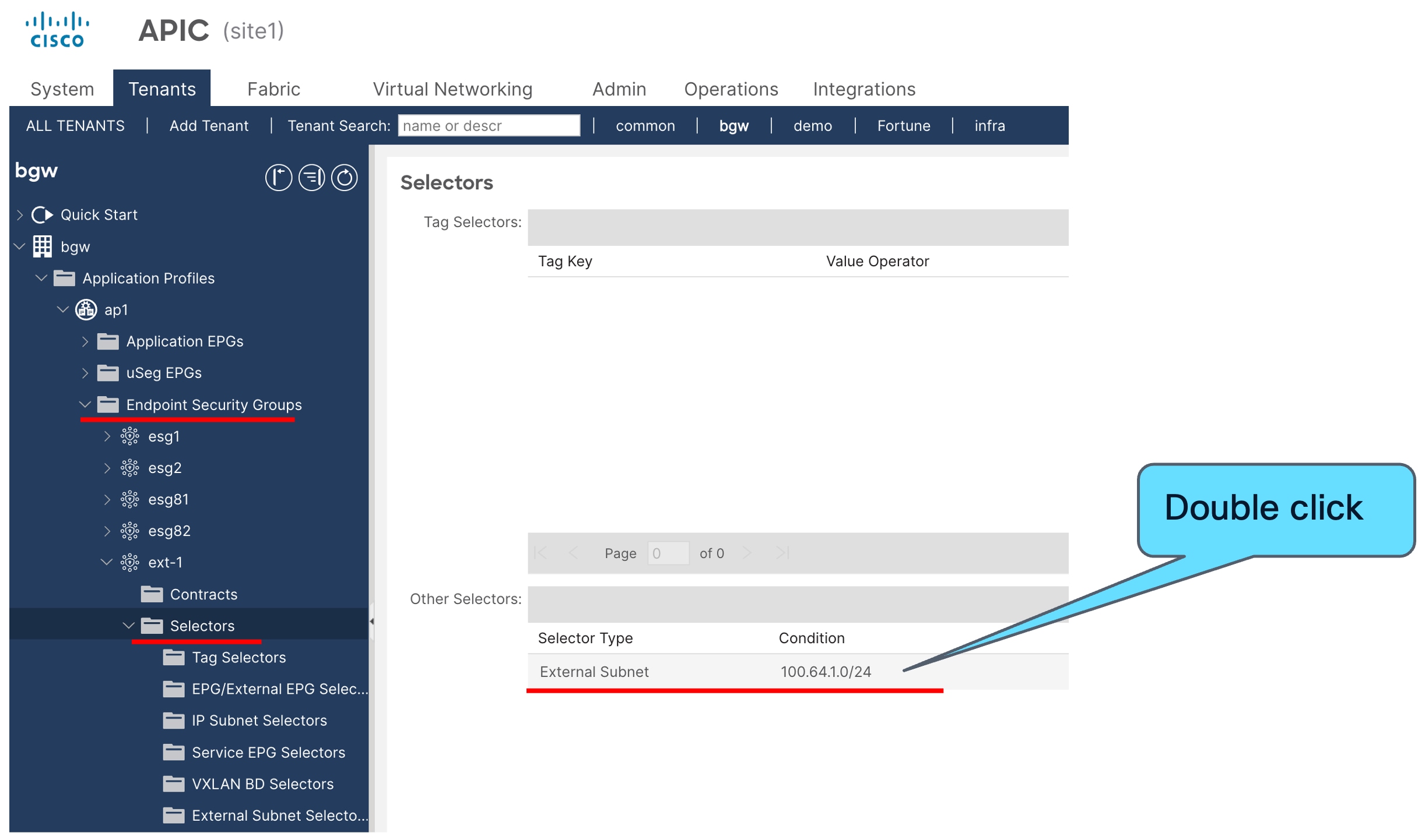
Figure 451. Check Shared and Submit
Control Plane Verification
The external router in ACI Site 1 learns 172.16.31.0/24 that is BD bd-share1 subnet in VRF share.
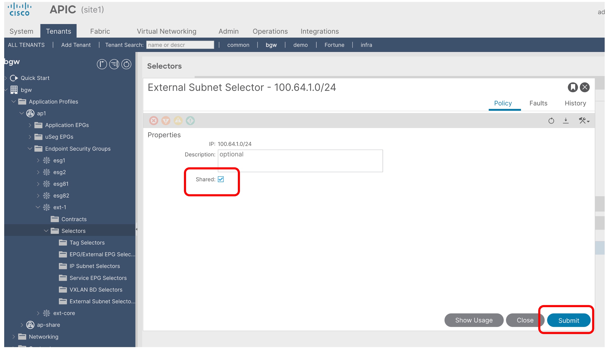
Figure 452. External router learns internal BD subnet
Data Plane Verification
The figure below illustrates the policy enforcement location and VNI translation behavior for traffic from 172.16.31.201 (VRF share) in ACI Site 2 to 100.64.1.10 (VRF vrf1) in ACI Site 1. In this case, ingress leaf performs “VRF switch” also known as VRF re-write for both directions.
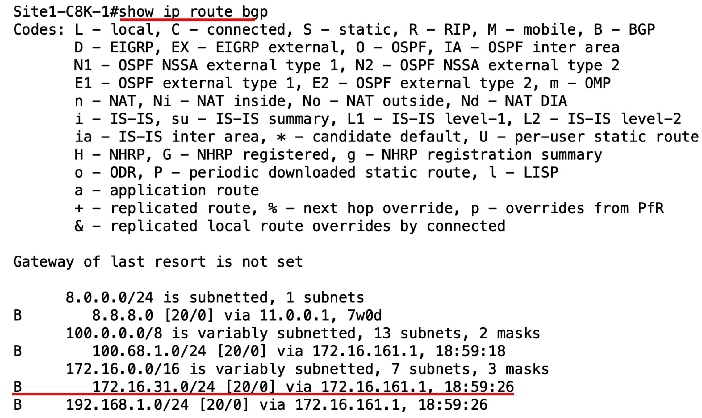
Figure 453. ACI Site 2 VRF share to ACI Site 1 VRF vrf1 L3Out, ingress leaf performs VRF switch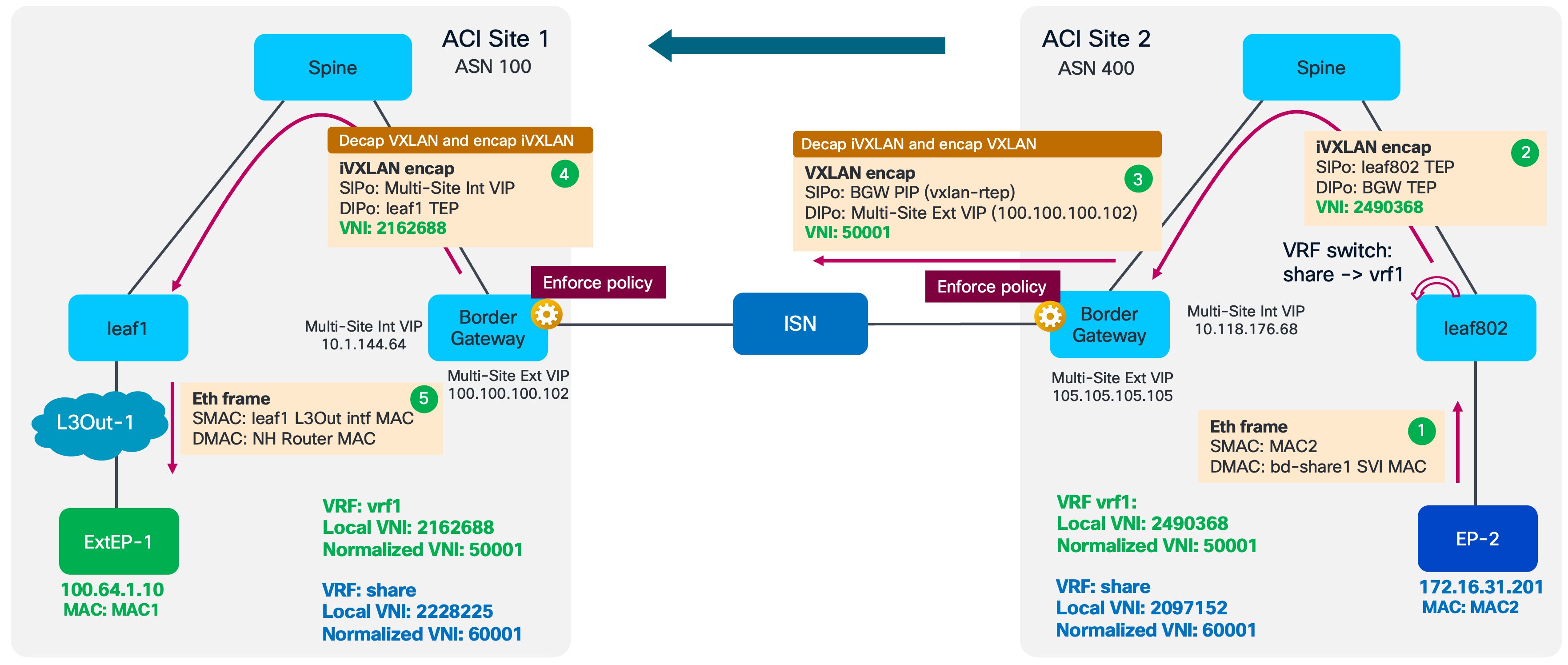
Figure 454. ACI Site 1 VRF vrf1 L3Out to ACI Site 2 VRF share, ingress leaf performs VRF switch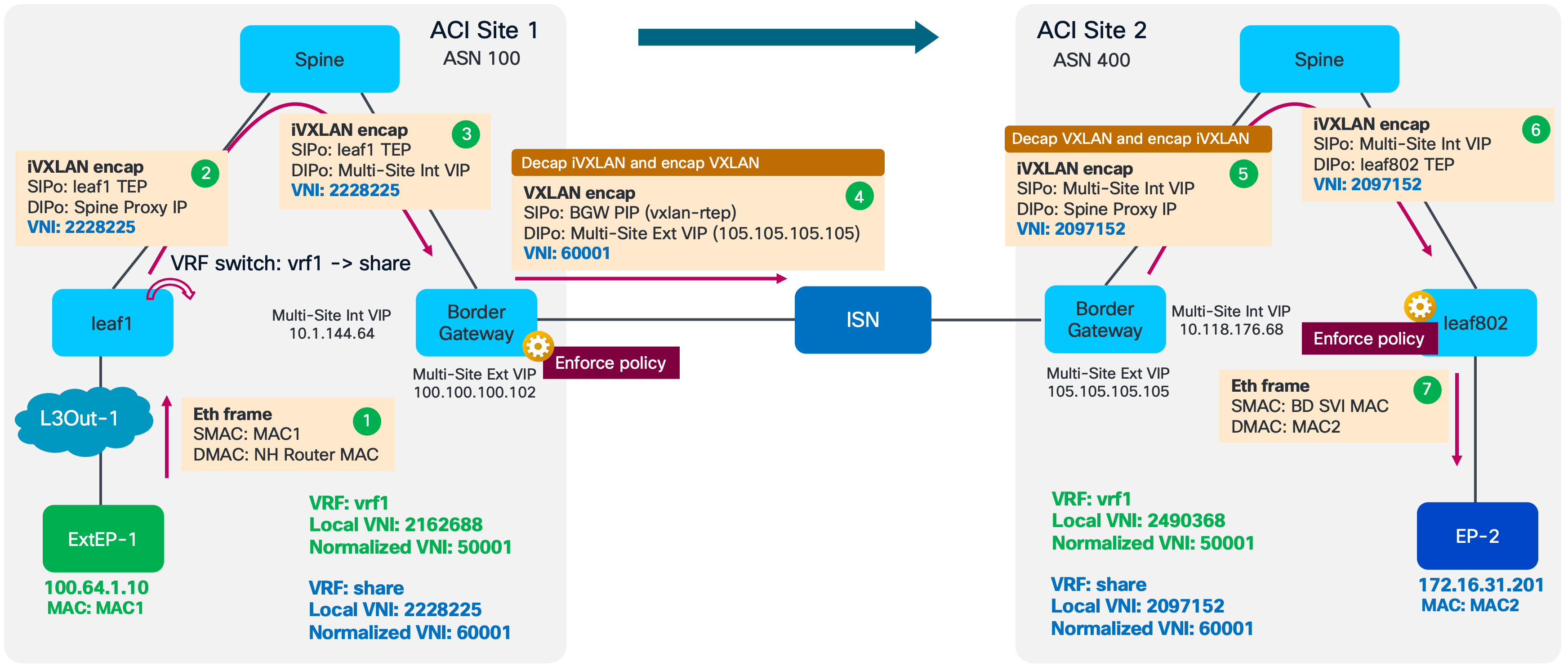
Figure 455. Data plane Shared L3Out communication
Ping result from an endpoint in ESG share1 in ACI Site 2 to an external endpoint in VRF vrf1 in ACI Site 1. The packet capture of the ICMP request from EP-2 to ExtEP-1 confirms that the Layer 3 (VRF) Normalized VNI of the destination VRF (VRF vrf1) is used in the VXLAN header for inter-site data plane forwarding.
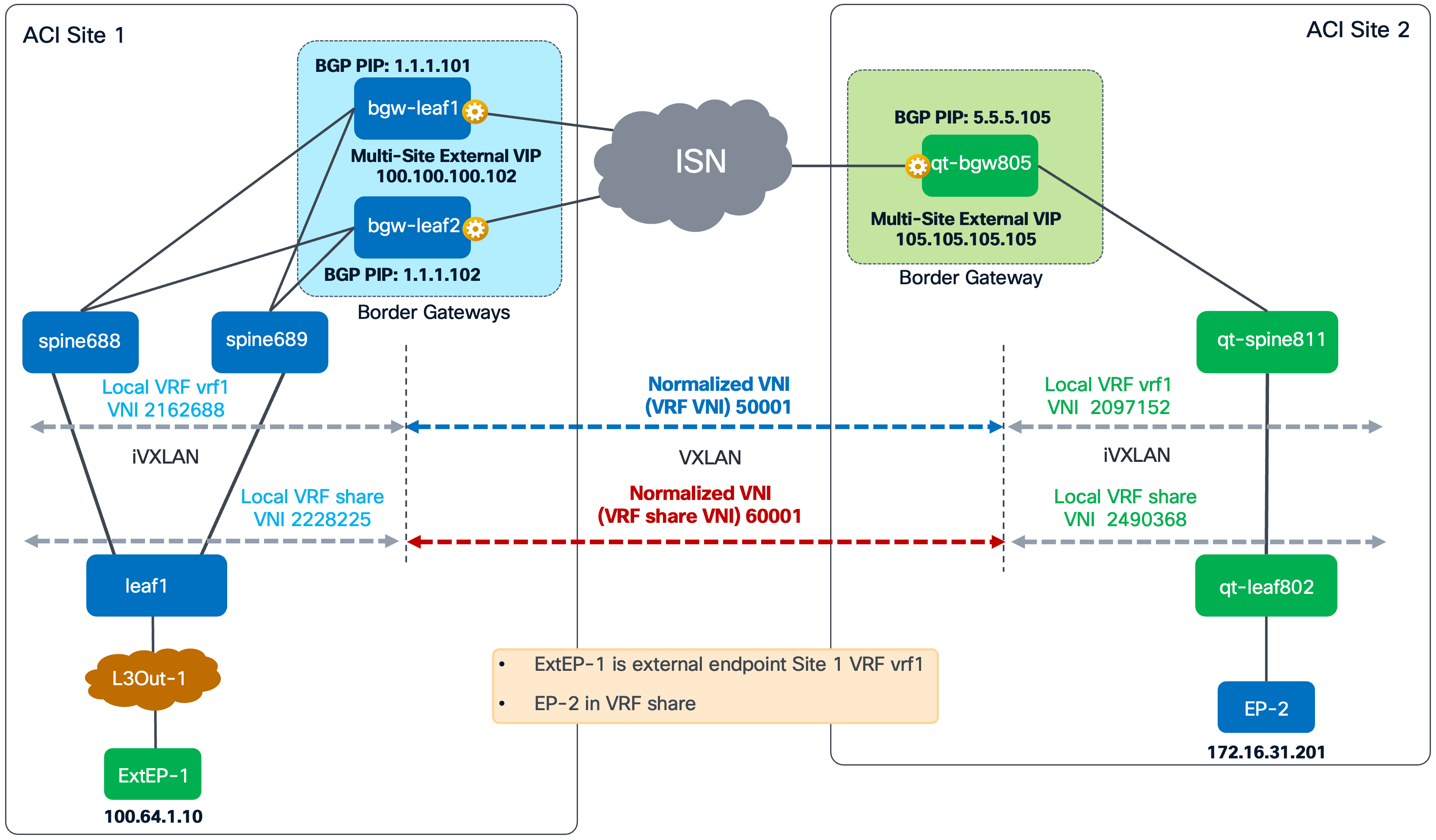
Figure 456. ICMP request from EP-2 (172.16.31.201) to ExtEP-1 (100.64.1.10)
The packet capture of the ICMP reply from ExtEP-1 to EP-2 confirms that the Layer 3 (VRF) Normalized VNI of the destination VRF (VRF share) is used in the VXLAN header for inter-site data plane forwarding.
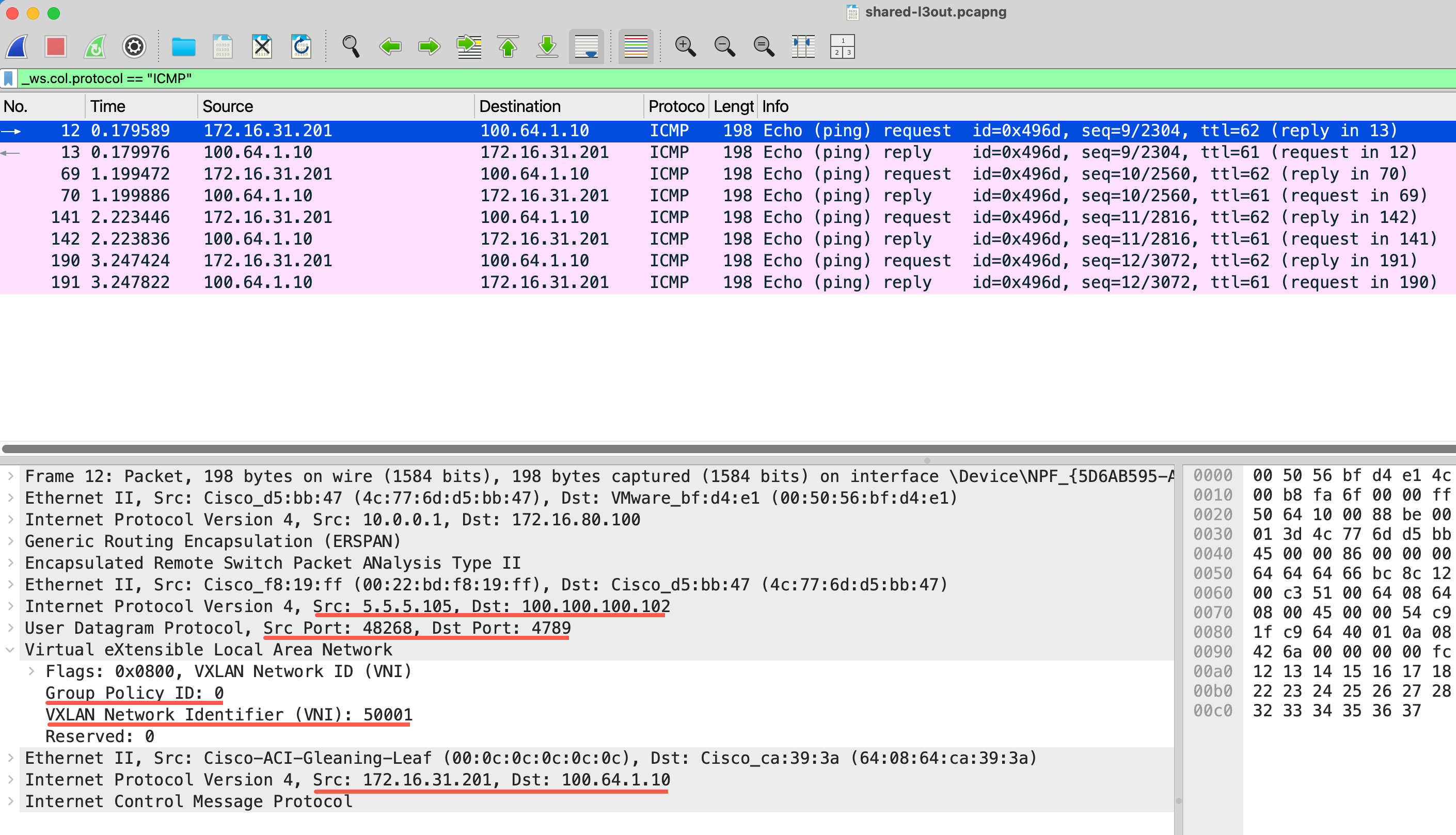
Figure 457. ICMP reply from ExtEP-1 (100.64.1.10) to EP-2 (172.16.31.201)
The figure below illustrates the policy enforcement location for traffic between 172.16.31.201 (an endpoint in ESG share1 ACI Site 2 VRF share) and 100.64.1.10 (an external endpoint in ESG ext-1 in ACI Site 1 VRF vrf1). In both directions, after the ingress leaf performs the “VRF switch” policy enforcement is identical to that described in Use Case 5: North-South Communication Across ACI Sites with Stretched BDs
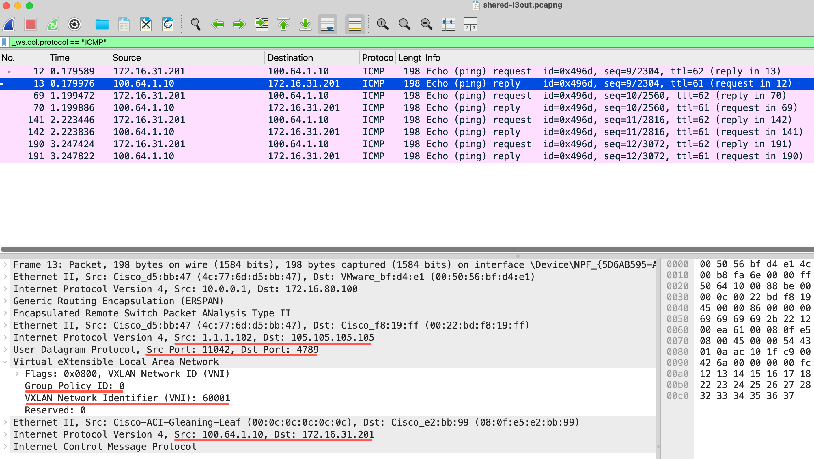
Figure 458. Local endpoint in ACI Site 2 VRF share to external endpoint in ACI Site 1 VRF vrf1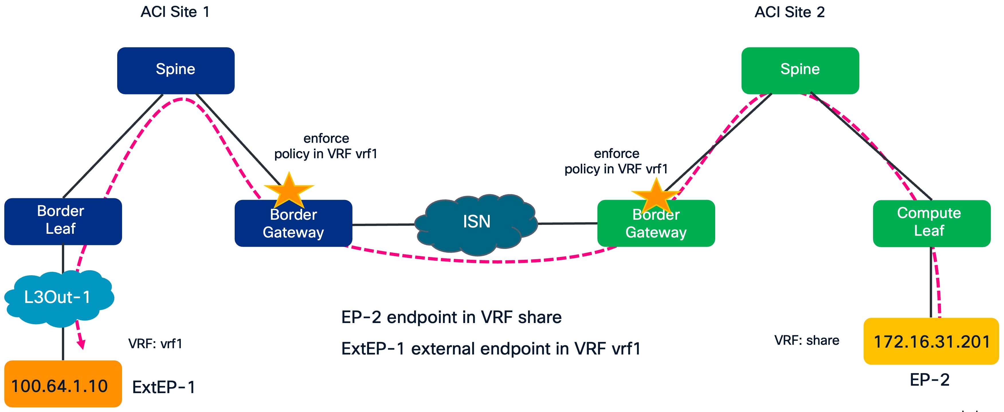
Figure 459. External endpoint in ACI Site 1 VRF vrf1 to local endpoint in ACI Site 2 VRF share
ACI Site 2 compute leaf does not apply the policy. Instead, ACI Site 2 Border Gateway applies the policy. ACI Site 1 Border Gateway applies the policy. ACI Site 1 Border Leaf does not apply the policy since the policy was already applied by the Border Gateway. ACI Border Leaf (node-101) does not apply the policy.
Instead, Border Gateway applies the policy in the destination VRF. ACI Site 2 Border Gateway does not apply the policy. Instead, ACI Site 2 compute leaf applies the policy in the destination VRF.
Use Case 12: Service Node Integration
This section explains PBR (Policy Based Redirect) for L4–L7 service integration in an ACI-to-ACI deployment through Border Gateways. For inter-site communication, contracts are applied in both the source and the destination sites, hence service insertion is handled independently within each site.
Each site may connect its own firewall devices, operating in Active/Standby mode, Active/Active mode, or as multiple independent firewalls with symmetric PBR (Policy Based Redirect). Firewall deployment is independent for each site, and the Service Bridge Domain (BD) can be entirely local to the site without requiring deployment on the Border Gateway. This means the Service BD does not need to be stretched or deployed on the Border Gateway to function properly within that site. Consumer and Provider Bridge Domains (BDs) can be either stretched across sites or remain local to each site. It is a valid design option for one site to deploy a firewall while another site operates without one. The site with the firewall can redirect traffic to its local firewall for traffic that is local to that site, for traffic arriving from the remote site, and for traffic destined toward the remote site. However, the remote site that does not have a local firewall cannot redirect traffic to the firewall deployed at the other site. However, for consistent security and policy enforcement, this guide recommends deploying firewalls at both source and destination sites. The Endpoint Security Groups (ESGs) involved in these relationships can be standard ESGs (for example ESG esg1, esg2) or ESGs configured with an external subnet to represent an external network (for example ESG ext-1).
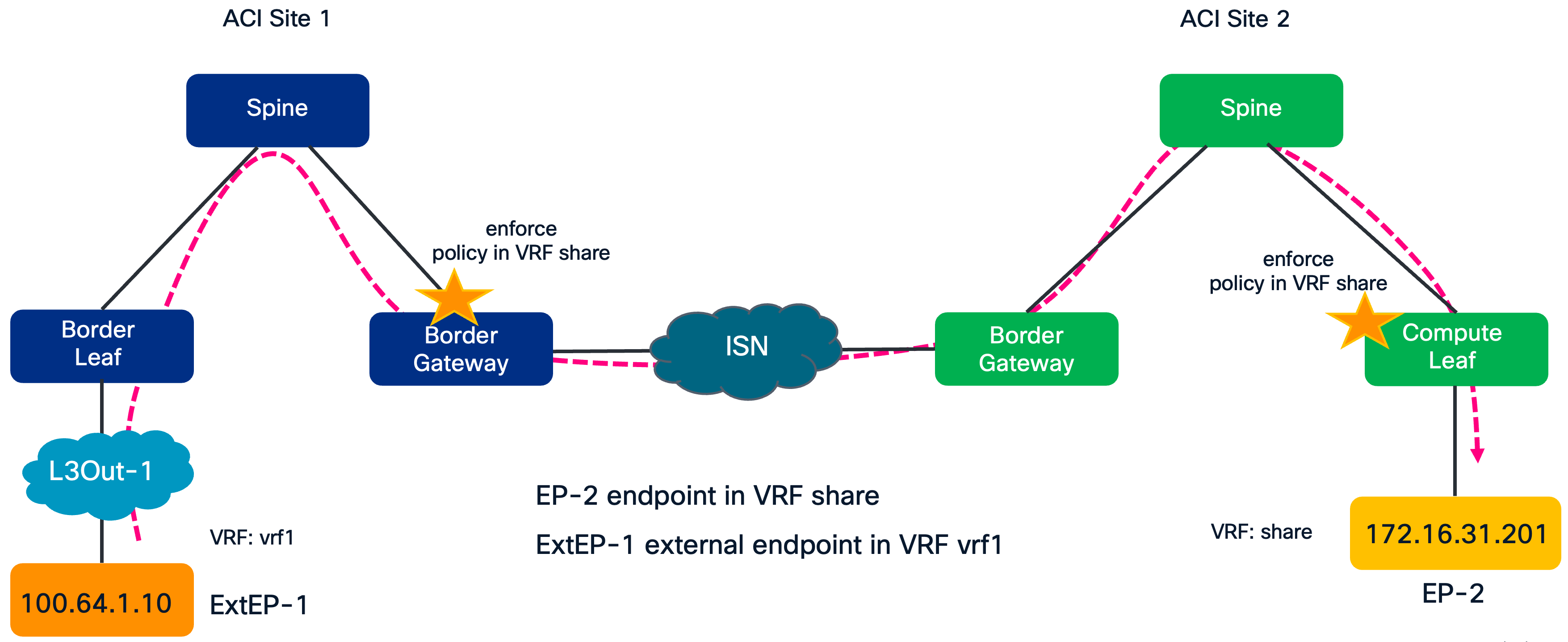
Figure 460. Firewall Insertion Topology
Below is a logical diagram with a contract between esg1 and esg2, the expectation is that traffic flow between esg1 and esg2 is redirected to the local firewall in each site independently.
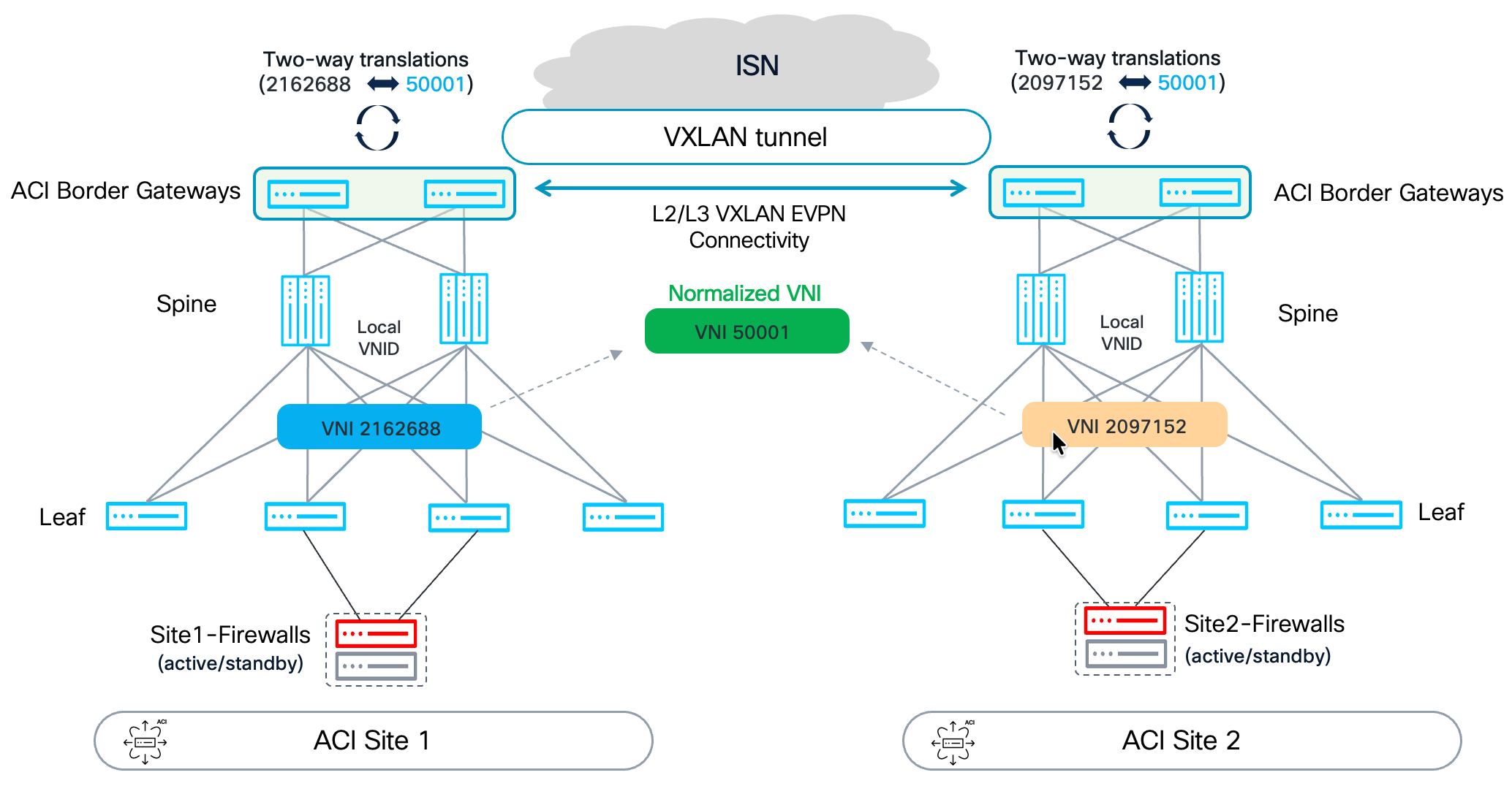
Figure 461. Firewall Insertion Logical Diagram
As shown in the figure above, both the consumer and provider are locally connected endpoints. However, as mentioned previously it is also possible for the consumer and provider to be external endpoints; for example, the consumer could be ESG esg1, and the provider could be ESG ext-1.
The following diagram illustrates the traffic flow originating from esg1 in ACI Site 1 to esg2 in ACI Site 2. Incoming traffic arriving from a remote site is always redirected by the Border Gateway in the receiving site.
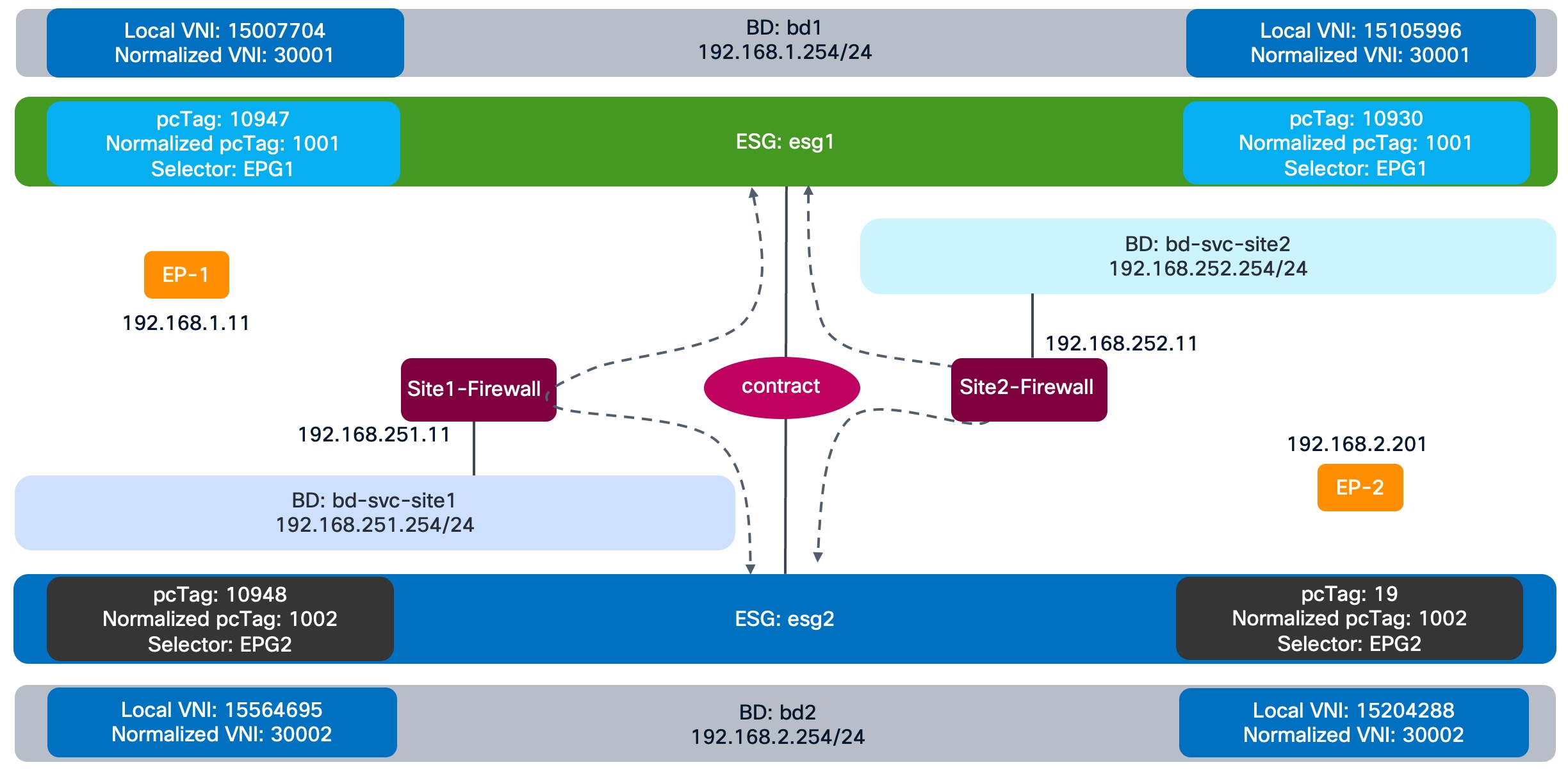
Figure 462. Flow from ACI Site 1 esg1 endpoint to ACI Site 2 esg2 endpoint
Since in the example in figure above the compute leaf in Site 1 does not have the pcTag information of the destination endpoint (EP-2), it forwards the traffic to the Site 1 Border Gateway, which maintains the complete pcTag information for both the source and destination endpoints. Upon receiving the traffic, the Site 1 Border Gateway performs a Policy-Based Redirect (PBR) and redirects the traffic to the Site 1 Firewall for inspection.
● 1a) EP-1 -> Site 1 leaf1 -> Site 1 Spine -> Site 1 Border Gateway -> Site 1 Spine -> Site 1 leaf601 -> Site 1 Firewall
● 1b) Site 1 Firewall -> Site 1 leaf601 -> Site 1 Spine -> Site 1 Border Gateway -> ISN -> Site 2 Border Gateway -> Site 2 Spine -> Site 2 leaf802 -> Site 2 Firewall
● 1c) Site 2 FW -> Site 2 leaf802 -> EP-2
Note: in the specific case where the BD of EP-2 is stretched across sites and also locally deployed on leaf1 in Site 1, it may happen that EP-2 IP information (and associated pcTag) will be learned on leaf1 based on data-plane activity. Under those specific circumstances, the PBR policy could be directly applied on leaf1 and traffic would be optimally redirected to the local firewall. The following diagram illustrates the flow for returning traffic from ESG2 in ACI Site 2 to ESG1 in ACI Site 1.
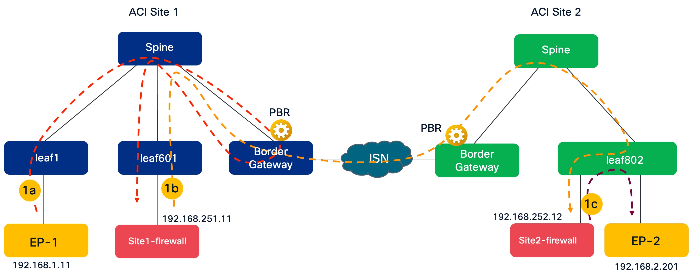
Figure 463. Returning flow from ACI Site 2 esg1 endpoint to ACI Site 1 esg2 endpoint
● 2a) EP-2 -> Site 2 leaf802 -> Site2 Spine -> Site 2 Border Gateway -> Site 2 Spine -> Site leaf802 -> Site 2 Firewall
● 2b) Site2 Firewall -> Site 2 leaf802 -> Site 2 Spine -> Site 2 Border Gateway -> ISN -> Site 1 Border Gateway -> Site 1 Spine -> Site 1 leaf1 -> Site 1 Spine -> Site 1 leaf601 -> Site 1 Firewall
● 2c) Site 1 Firewall -> Site 1 leaf601-> Site 1 Spine -> Site 1 leaf1 -> EP-1
Note: in the specific case where the BD of EP-1 is stretched across sites and also locally deployed on leaf802 in Site 2, it may happen that EP-1 IP information (and associated pcTag) will be learned on leaf802 based on data-plane activity. Under those specific circumstances, the PBR policy could be directly applied on leaf802 and traffic would be optimally redirected to the local firewall.
The following steps outline the primary configuration on both ACI Sites, assuming that esg1, esg2, and the required contract are already in place.
● Create a Bridge Domain (BD) for the service node, also known as the Service BD.
● Create the Firewall Logical Device.
● Create the Service Graph Template.
● Create the L4–L7 Redirection Policy.
● Deploy the Service Graph using the template.
For more detail information, please refer to this whitepaper: https://www.cisco.com/c/en/us/solutions/collateral/data-center-virtualization/application-centric-infrastructure/white-paper-c11-739971.html
The next section shows a configuration example for both ACI sites.
Firewall Insertion Configuration Details
In ACI Site 1, the Service BD is configured as Layer 3 with Unicast Routing enabled. The Service BD subnet does not need to be advertised externally or stretched across sites.
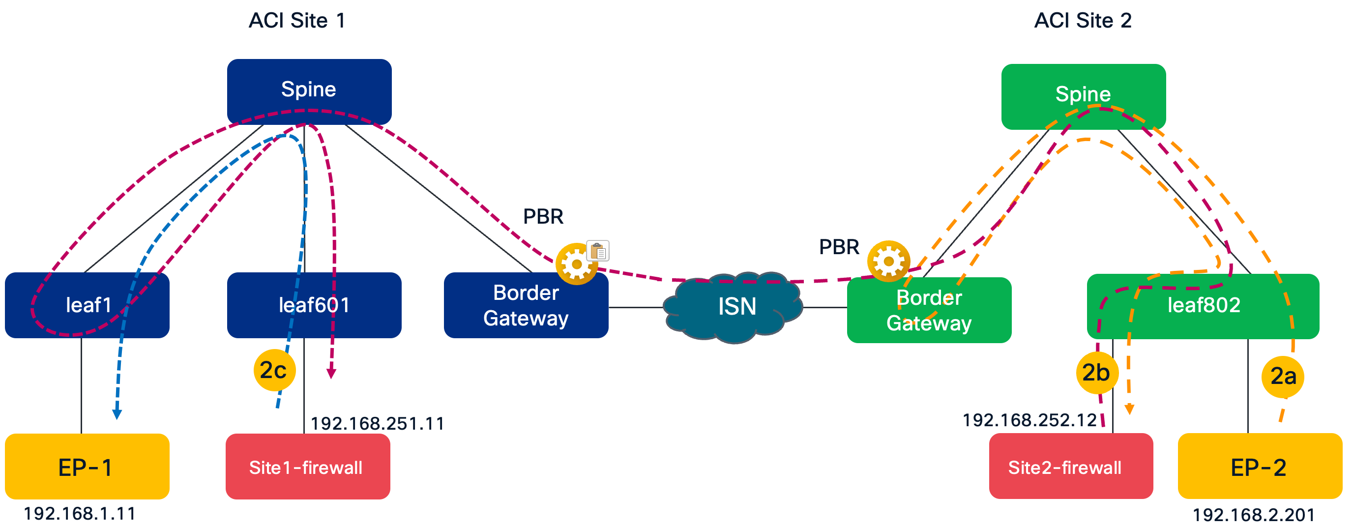
Figure 464. ACI Site 1 Service BD
For the ACI Site 1 service node, this deployment uses a virtual domain; however, the same principles apply to a physical domain. While this service node is configured using a one-arm interface, a two-arm interface configuration is also supported. Note that for a two-arm service, two separate service BDs need be defined, one for each interface. This example uses one-arm service node.
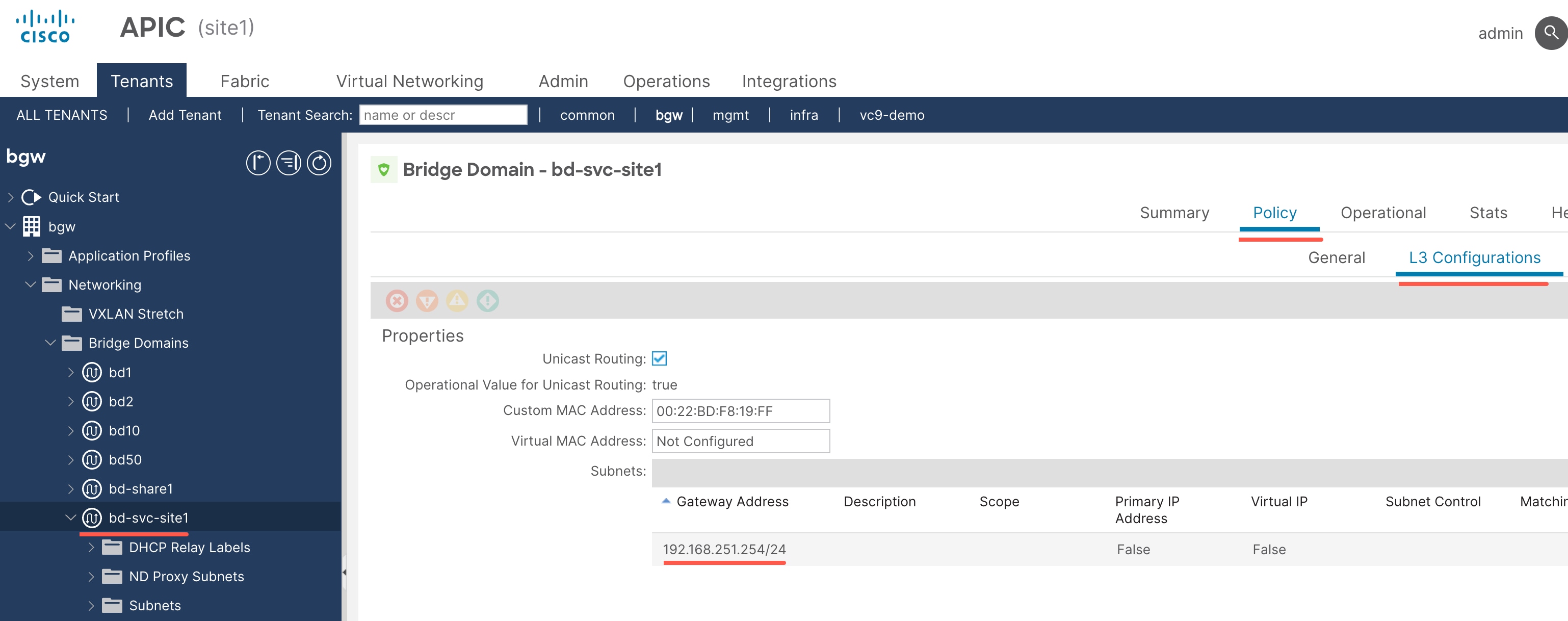
Figure 465. ACI Site 1 Service Node
The “Route Redirect” parameter in the Service Graph Template must be set to “true” as this deployment utilizes PBR.
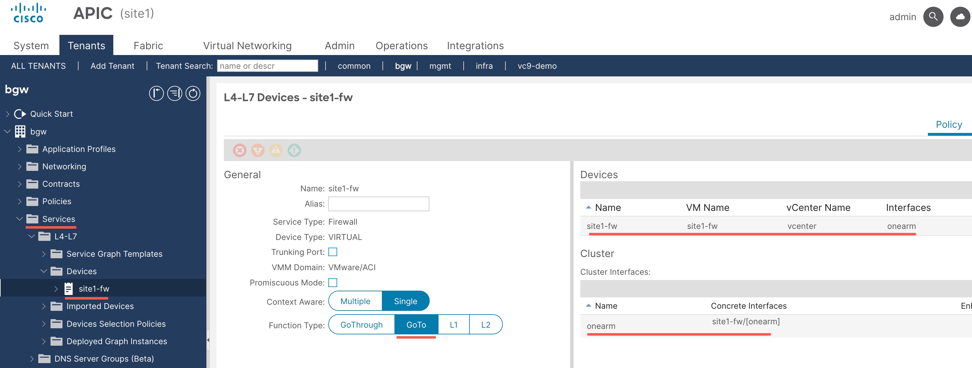
Figure 466. ACI Site 1 Service Graph Template
In this example, the IP SLA frequency is set to 3 seconds, resulting in ACI sending an ICMP probe to the service node every 3 seconds. Based on the Detect Multiplier value of 3, the service node is declared down after three consecutive probe failures.
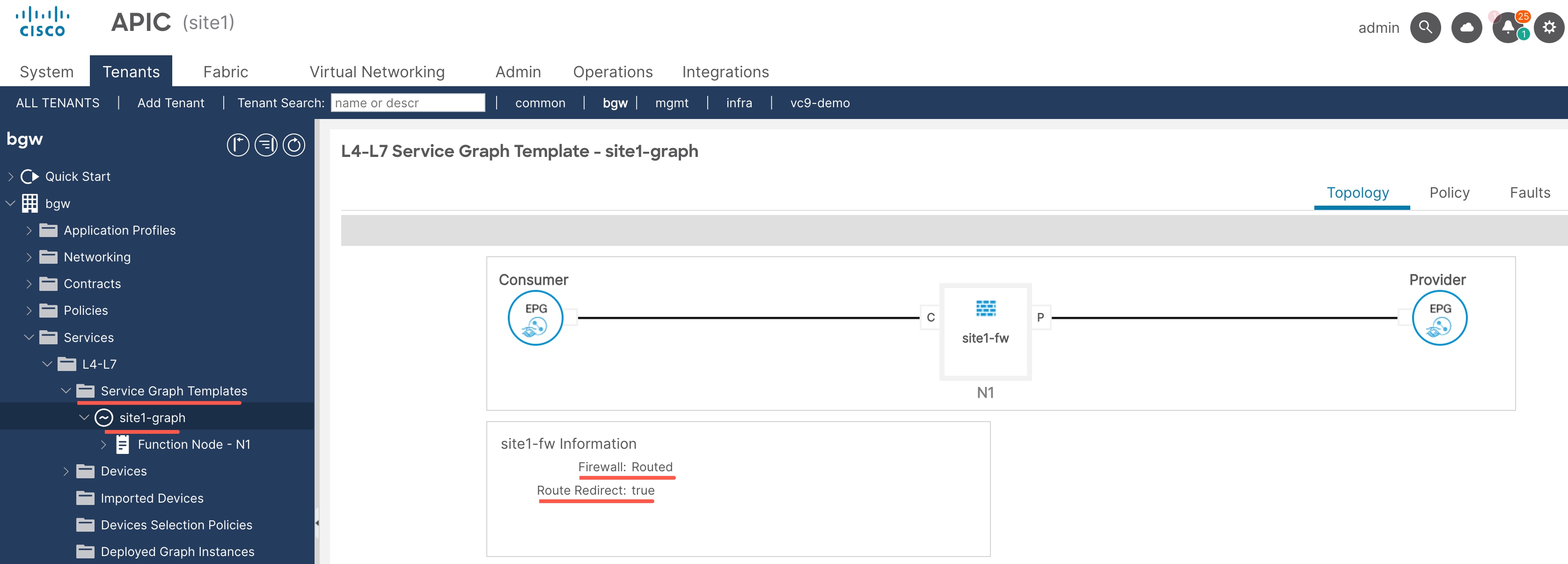
Figure 467. ACI Site 1 IP SLA Monitoring Policy
A Redirect Health Group (Health Group) in Cisco ACI Policy-Based Redirect (PBR) is a logical grouping of PBR destination IP addresses used to track the operational status of service nodes, such as firewalls or load balancers. The health group prevents traffic redirection to a service node that is down, avoiding traffic blackholing. To enable IP SLA monitoring, a Redirect Health Group must be configured. For more details, please refer to the Cisco ACI white paper on optional features available at https://www.cisco.com/c/en/us/solutions/collateral/data-center-virtualization/application-centric-infrastructure/white-paper-c11-739971.html#Optionalfeatures
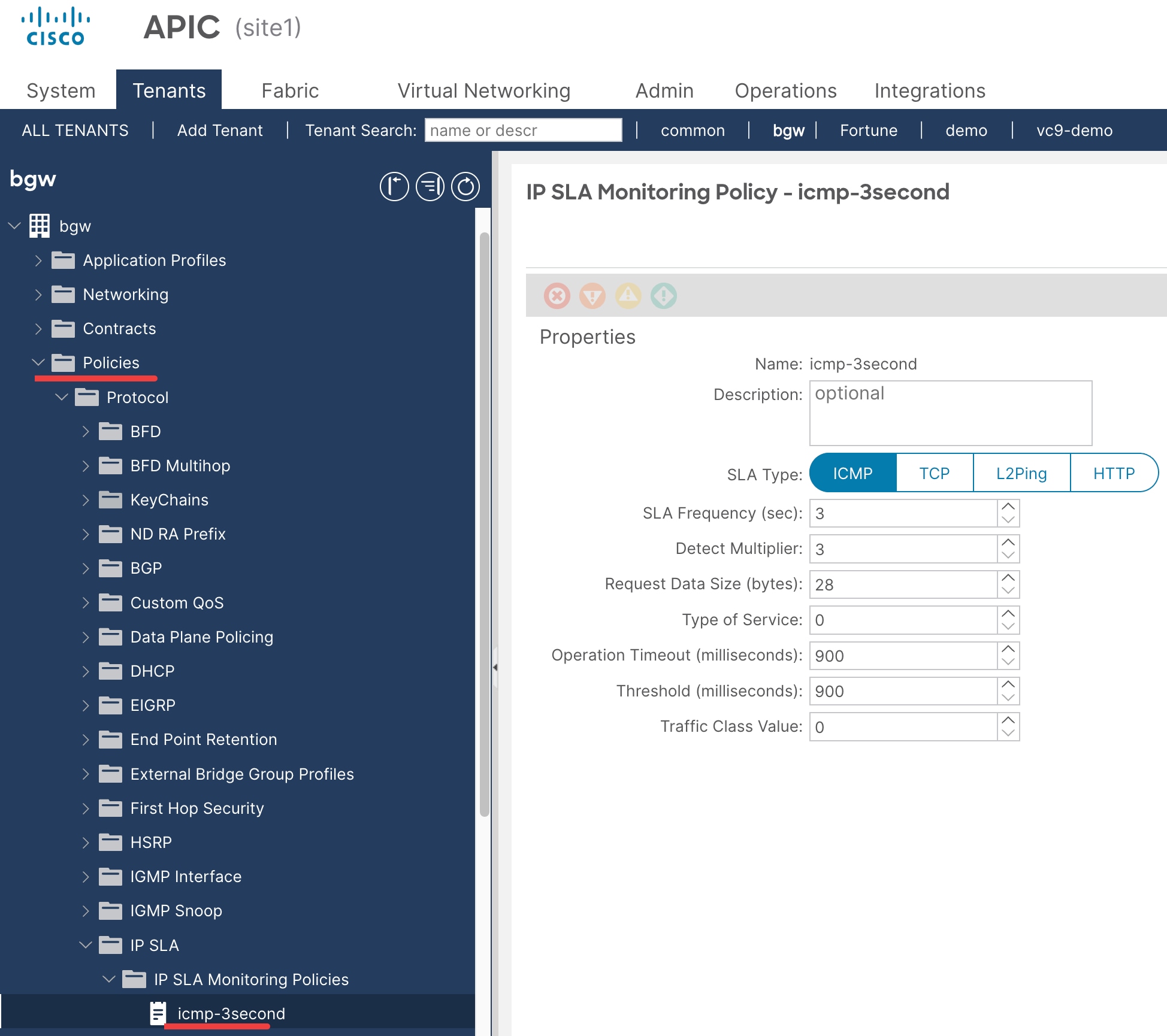
Figure 468. ACI Site 1 L4-L7 Redirect Health Group
L4-L7 Policy Based Redirect (also known as PBR policy) specifies where ACI fabric should redirect the traffic by specifying the destination IP and MAC addresses. Since this configuration example uses the IP SLA Monitoring Policy, MAC address configuration is not mandatory.
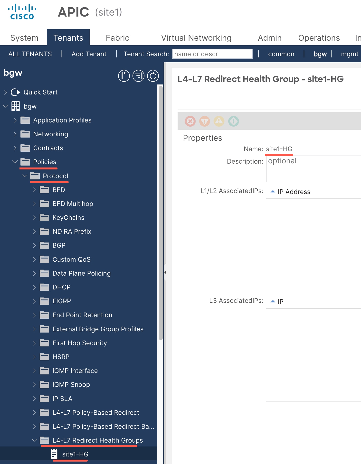
Figure 469. ACI Site 1 L4-L7 Policy-Based Redirect Policy
To apply the service graph to the contract subject, right click on the graph template and choose “Apply L4-L7 Service Graph Template”.
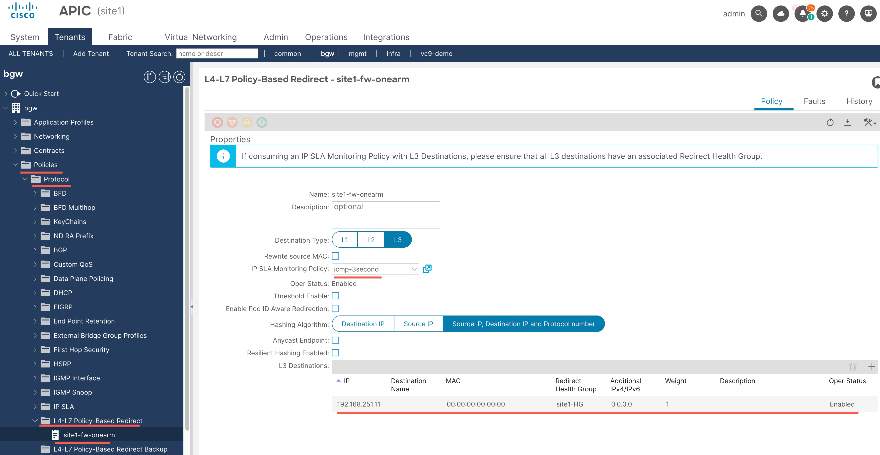
Figure 470. Apply Service Graph Template
From the menu, choose a consumer ESG, a provider ESG and a contract subject. In this example, choose esg1 as consumer, esg2 as provider and choose esg1-esg2/ip from Existing Contracts subjects.
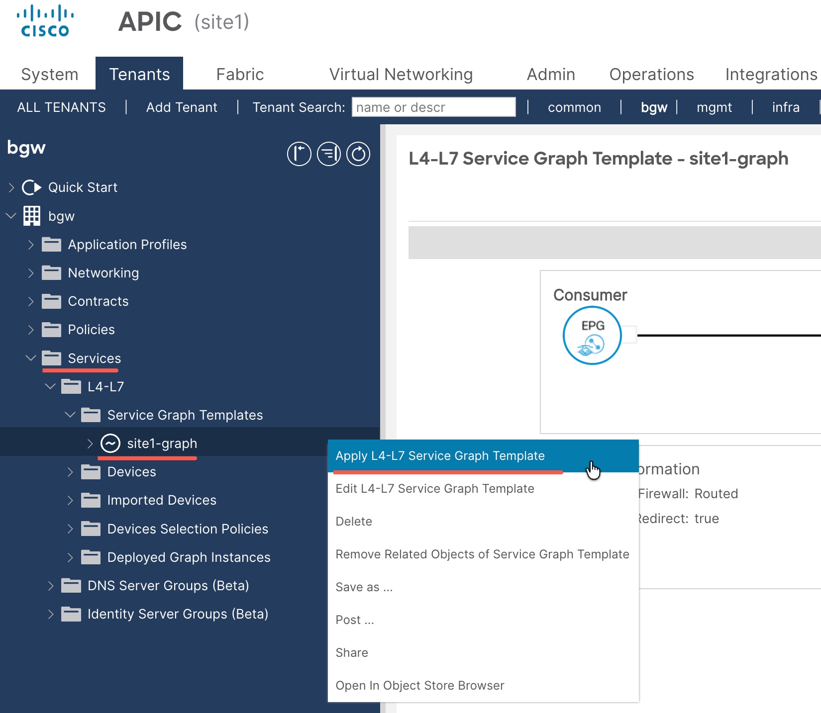
Figure 471. Choose ESGs and Contract subjects
Choose a service BD, a Redirect Policy and a Cluster interface for each connector: consumer and provider connector. In this example, choose bd-svc-site1 as the service BD, site1-fw-one-arm as the Redirect Policy and one-arm as the Cluster interface for both connectors.
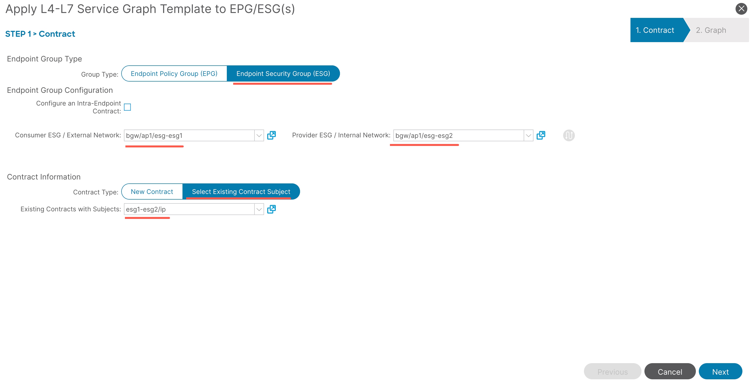
Figure 472. Consumer connector configuration
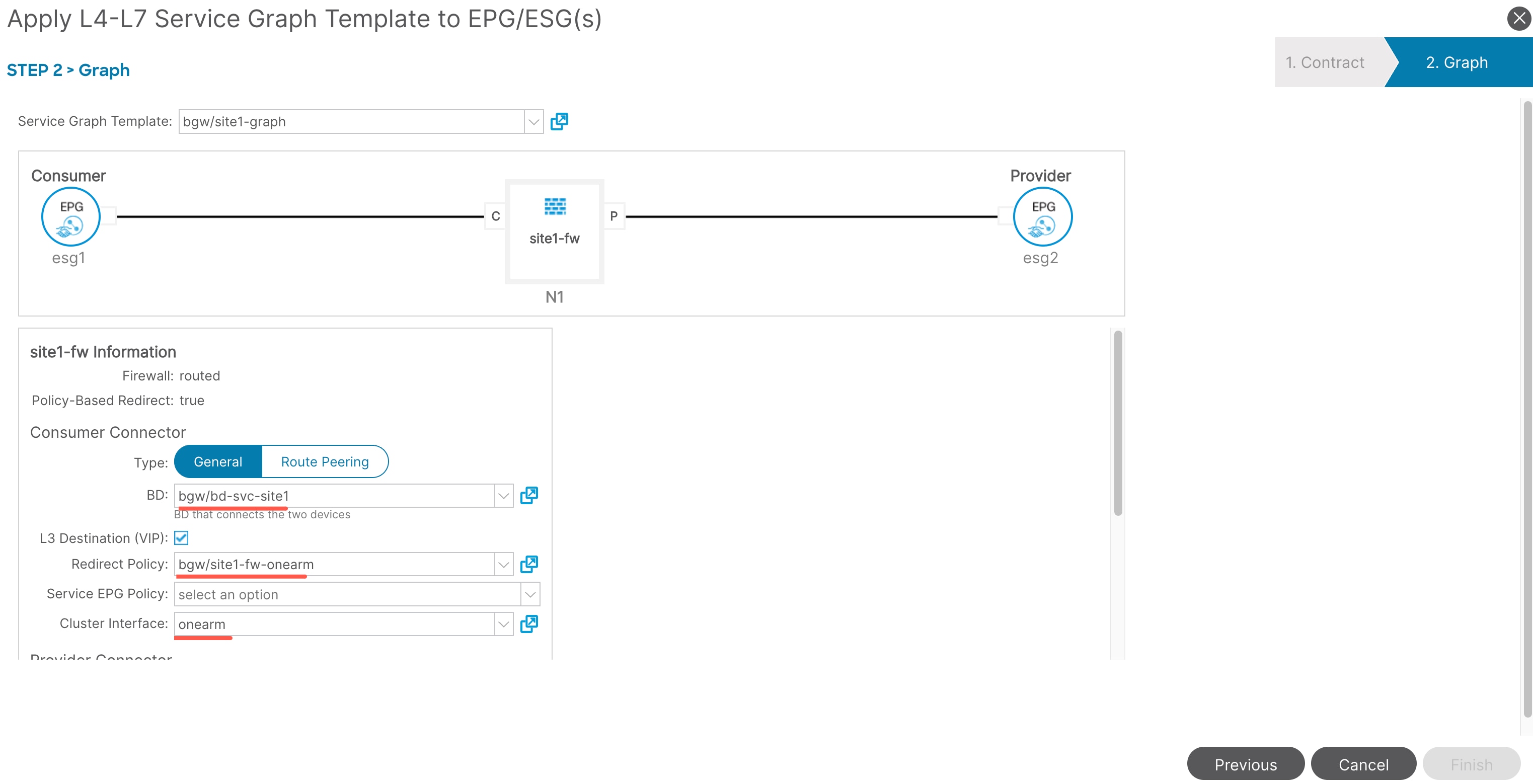
Figure 473. Provider connector configuration
Once the configuration is complete, click Finish. A Deployed Graph Instance will appear in the Deploy Graph Instances menu; verify that the status is “Applied” and that no faults are present.
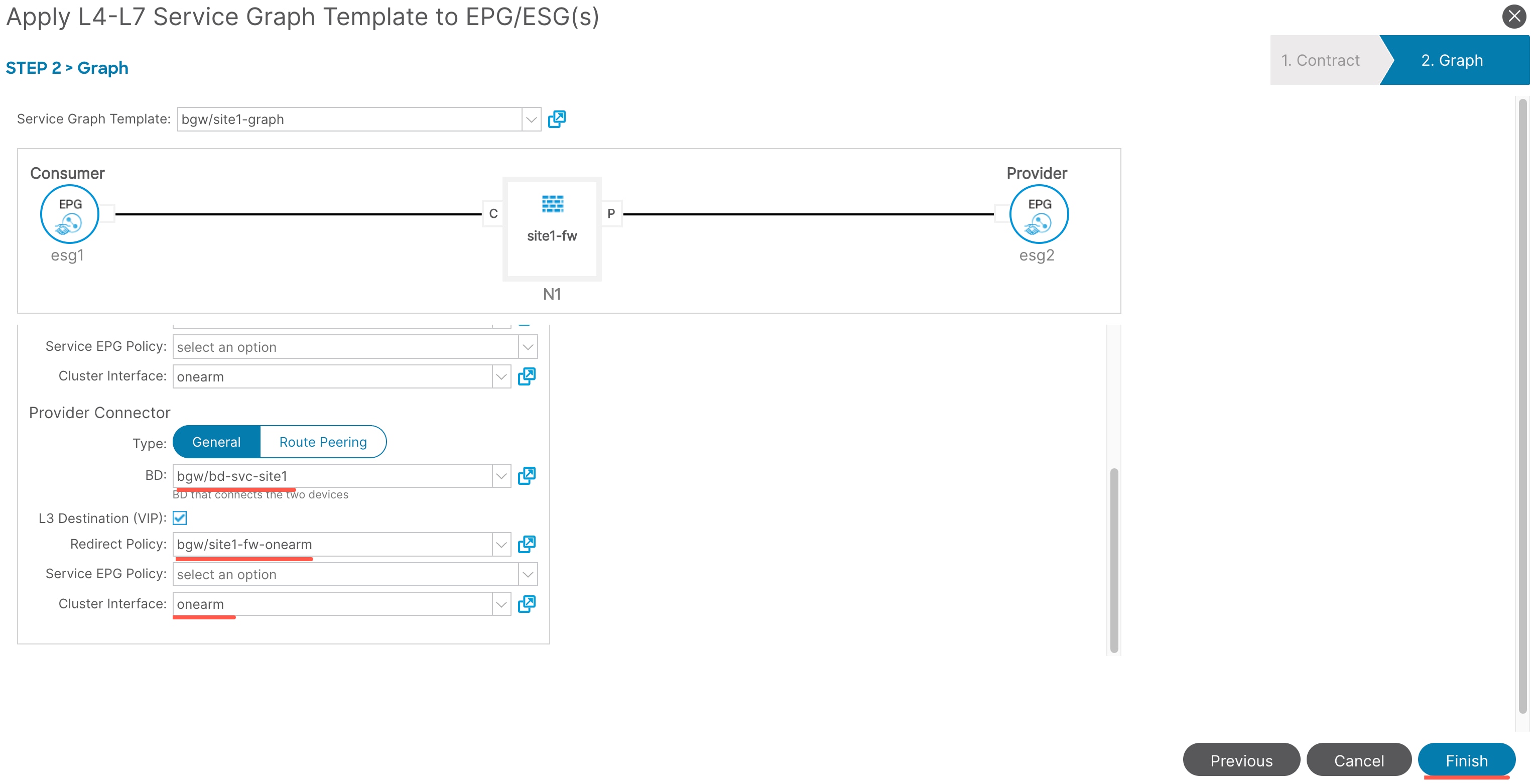
Figure 474. Deployed Graph Instance
As previously noted, service insertion is configured independently across ACI sites. The following screenshots show the corresponding configuration on ACI Site 2.
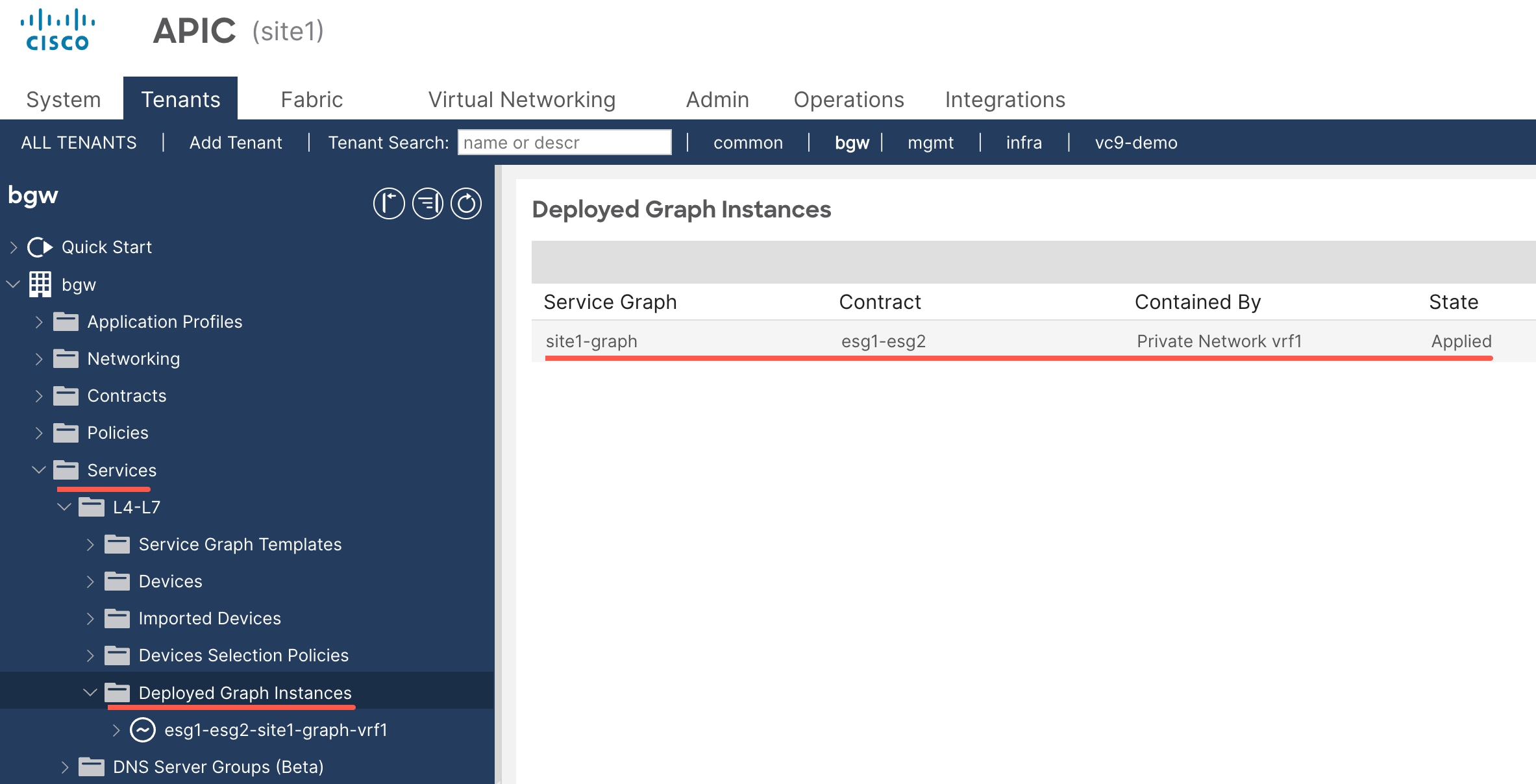
Figure 475. ACI Site 2 Service BD
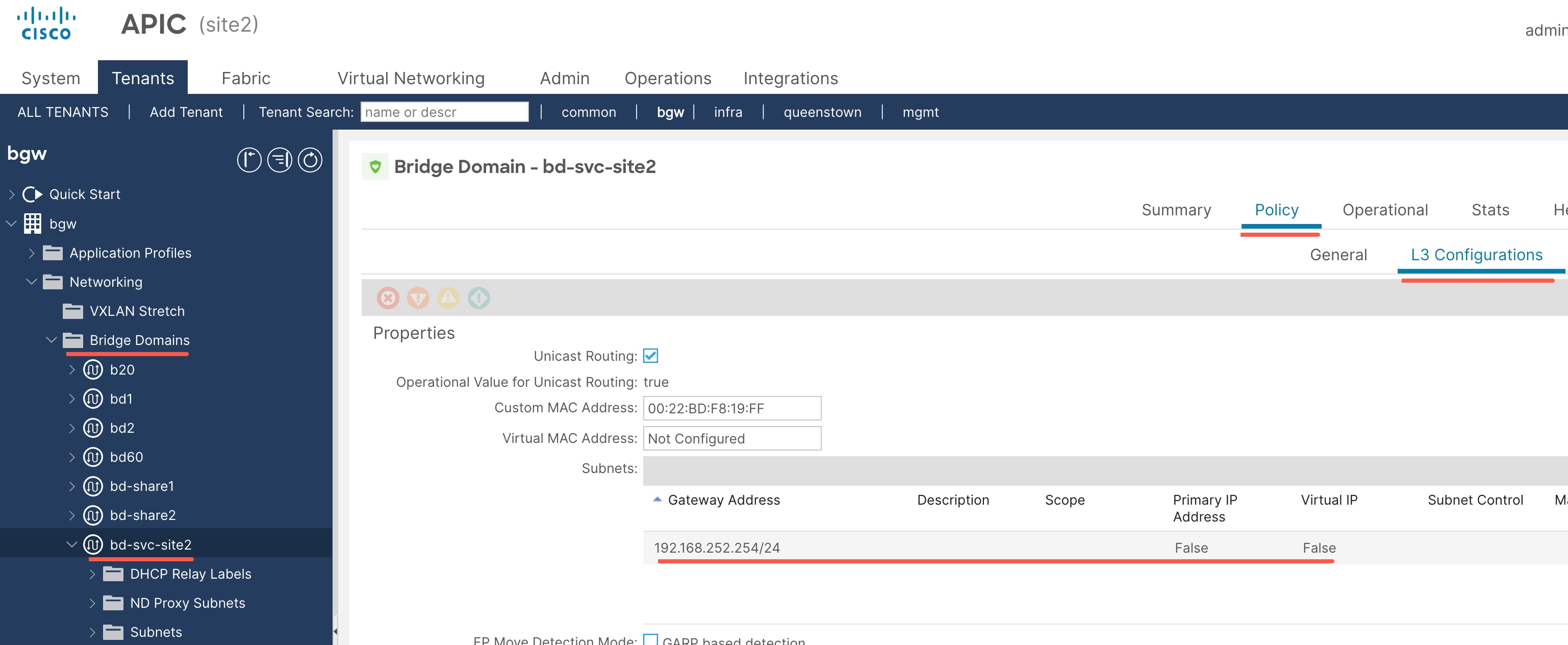
Figure 476. ACI Site 2 Service Node
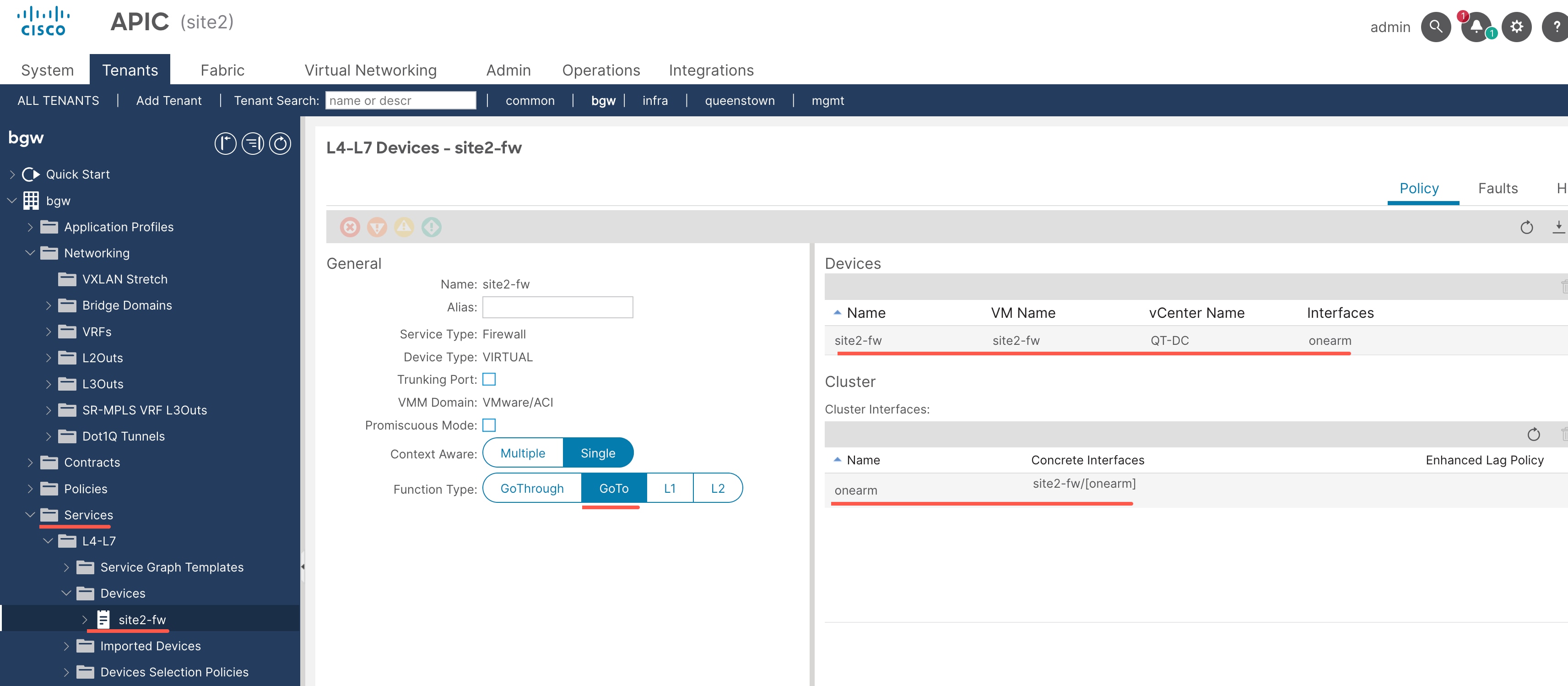
Figure 477. ACI Site 2 Service Graph Template
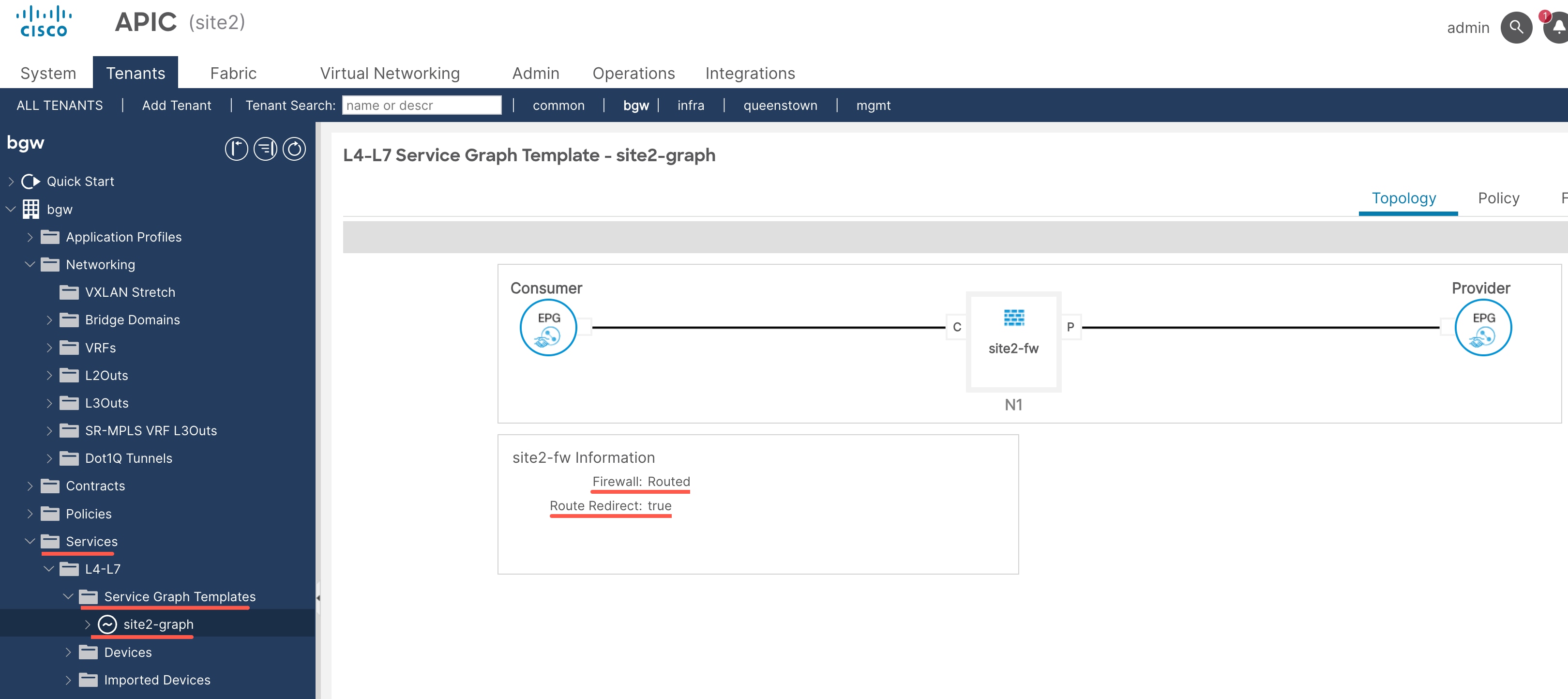
Figure 478. ACI Site 2 IP SLA Monitoring Policy
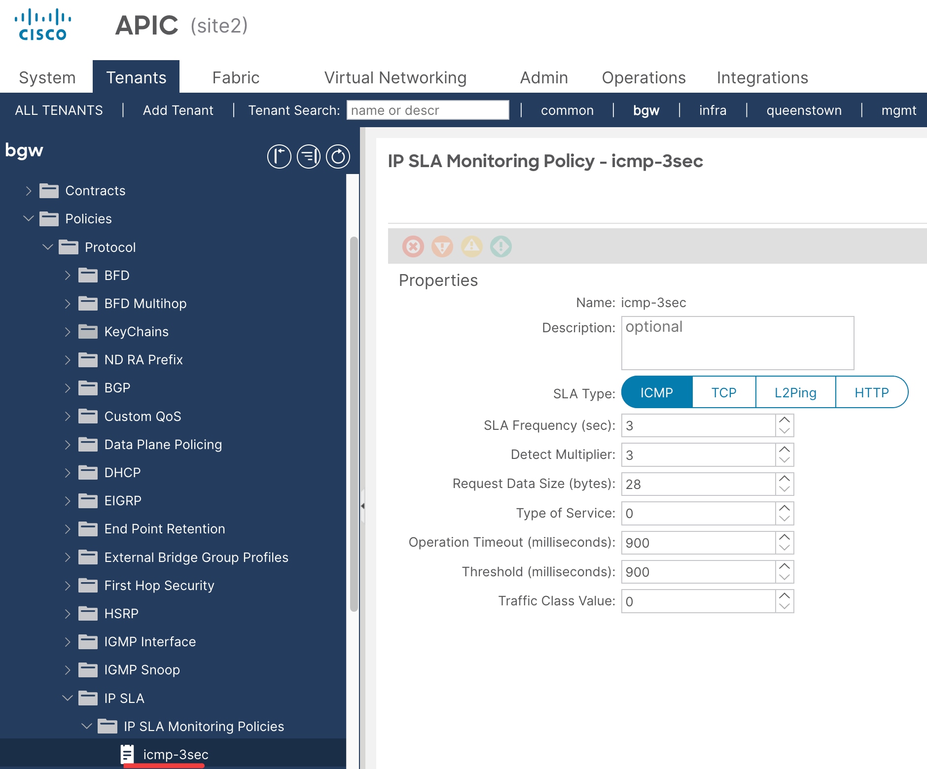
Figure 479. ACI Site 2 L4-L7 Redirect Health Group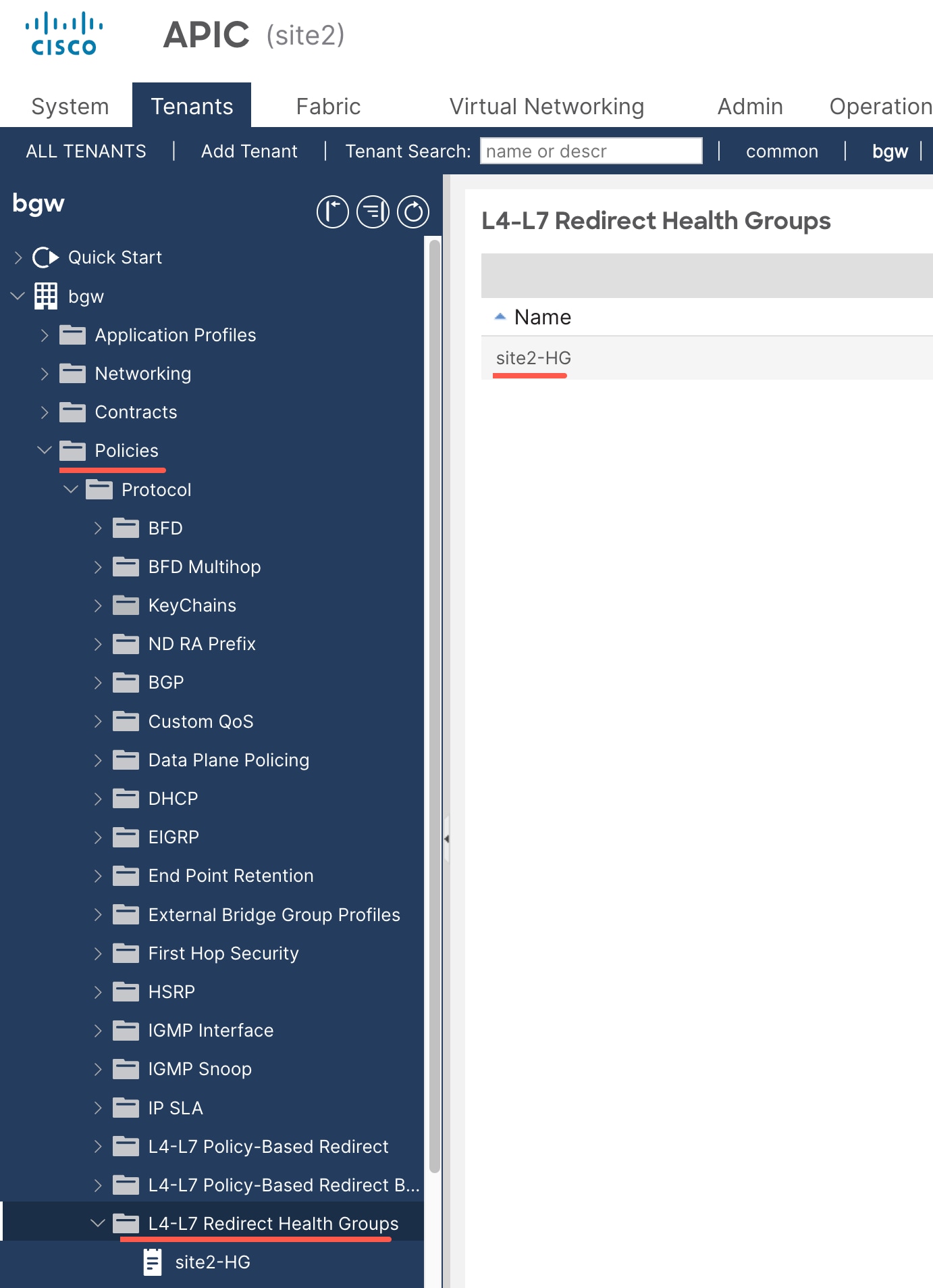
Figure 480. ACI Site 2 L4-L7 Policy-Based Redirect

Figure 481. Apply Service Graph site2-graph
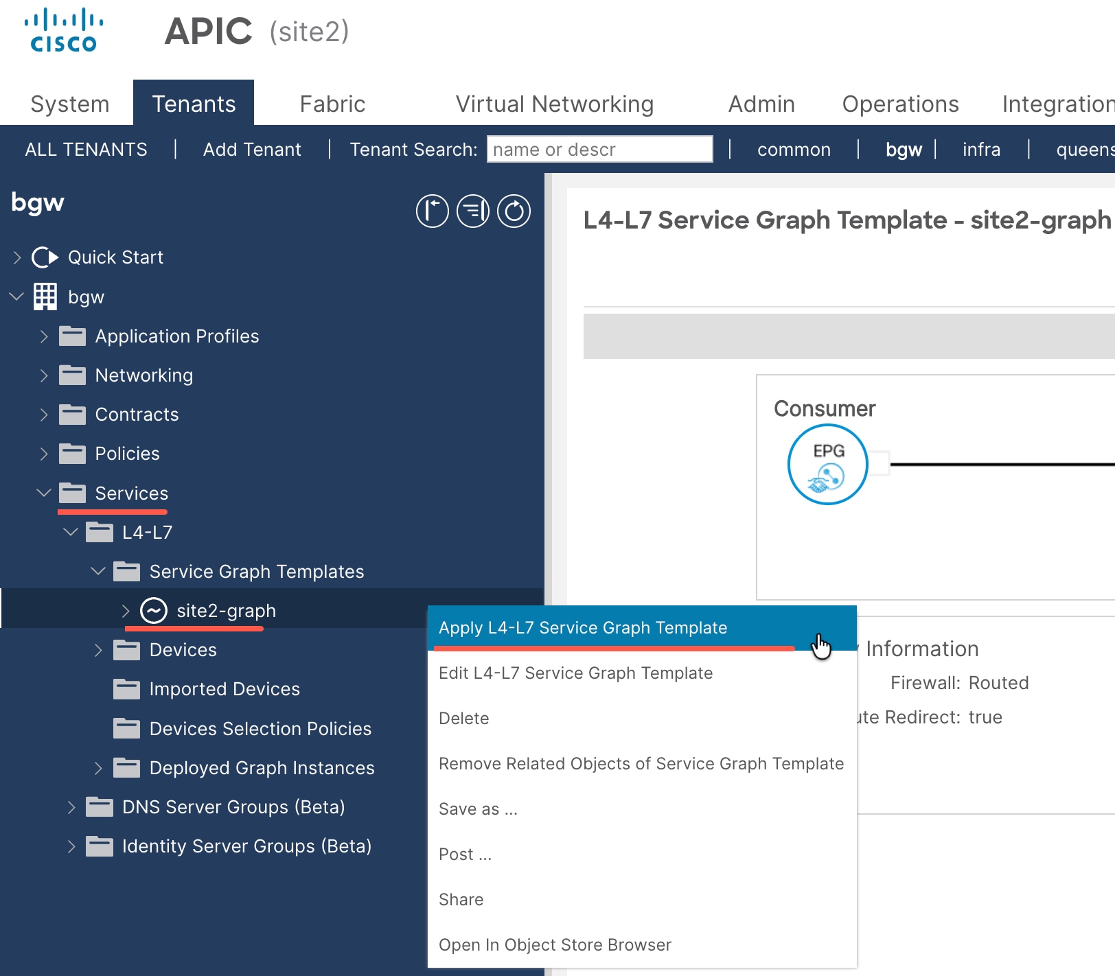
Figure 482. Choose proper ESG and Contract subject
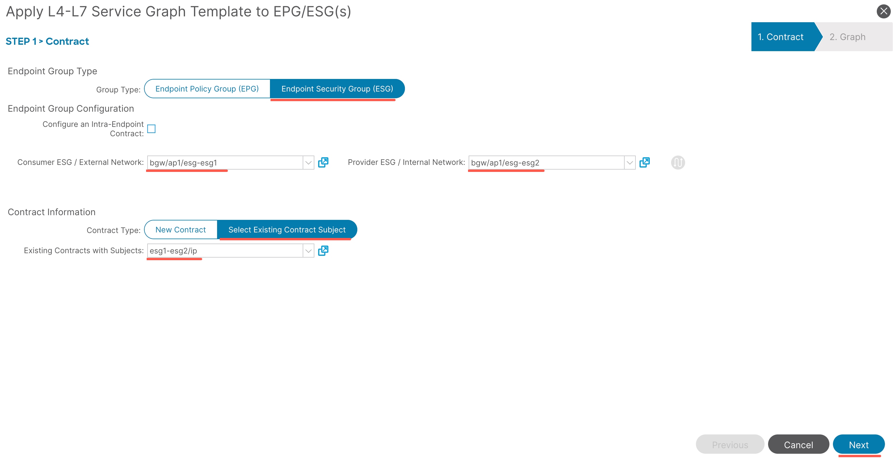
Figure 483. ACI Site 2 Consumer connector
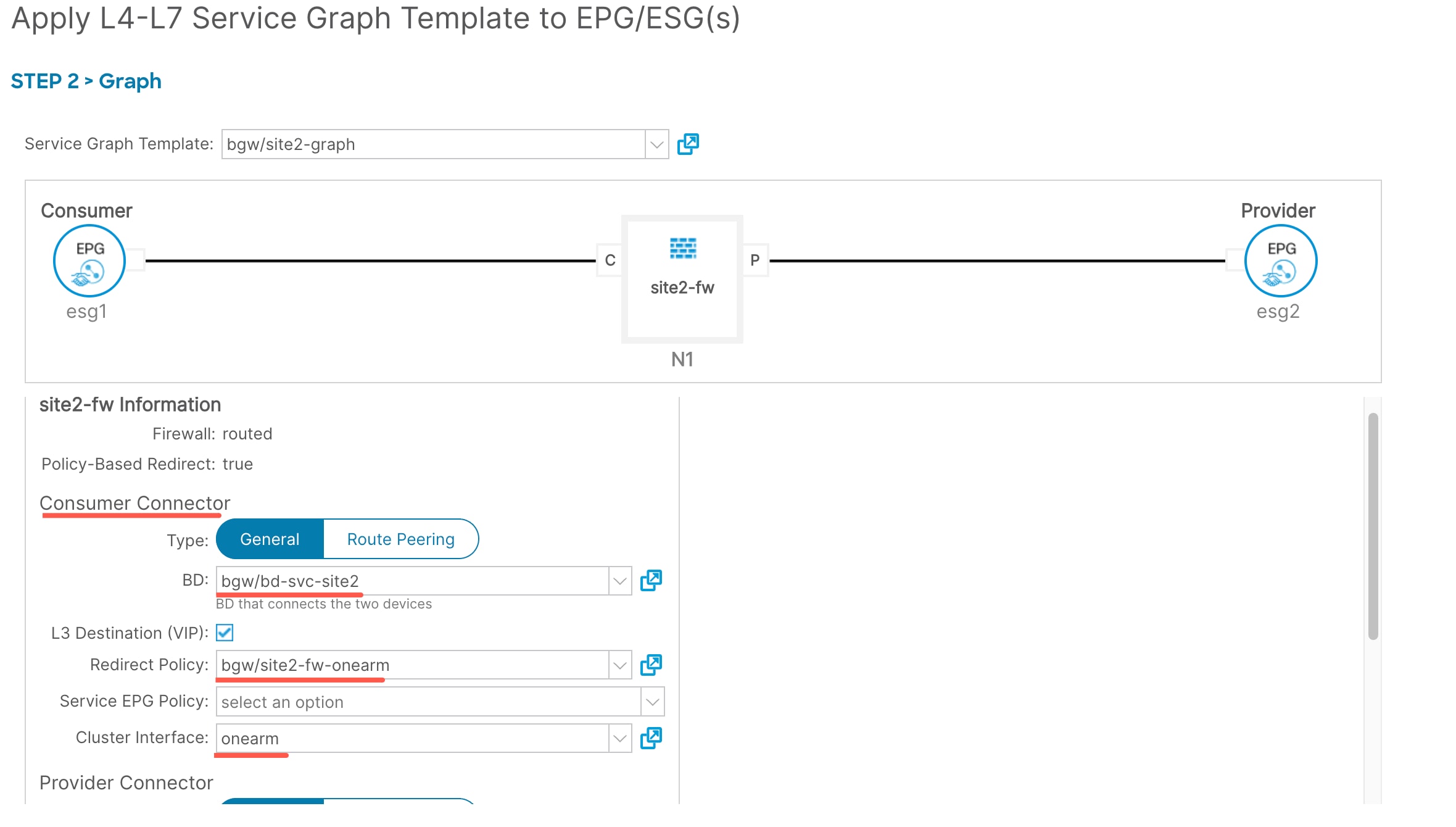
Figure 484. ACI Site 2 Provider connector click Finish to complete
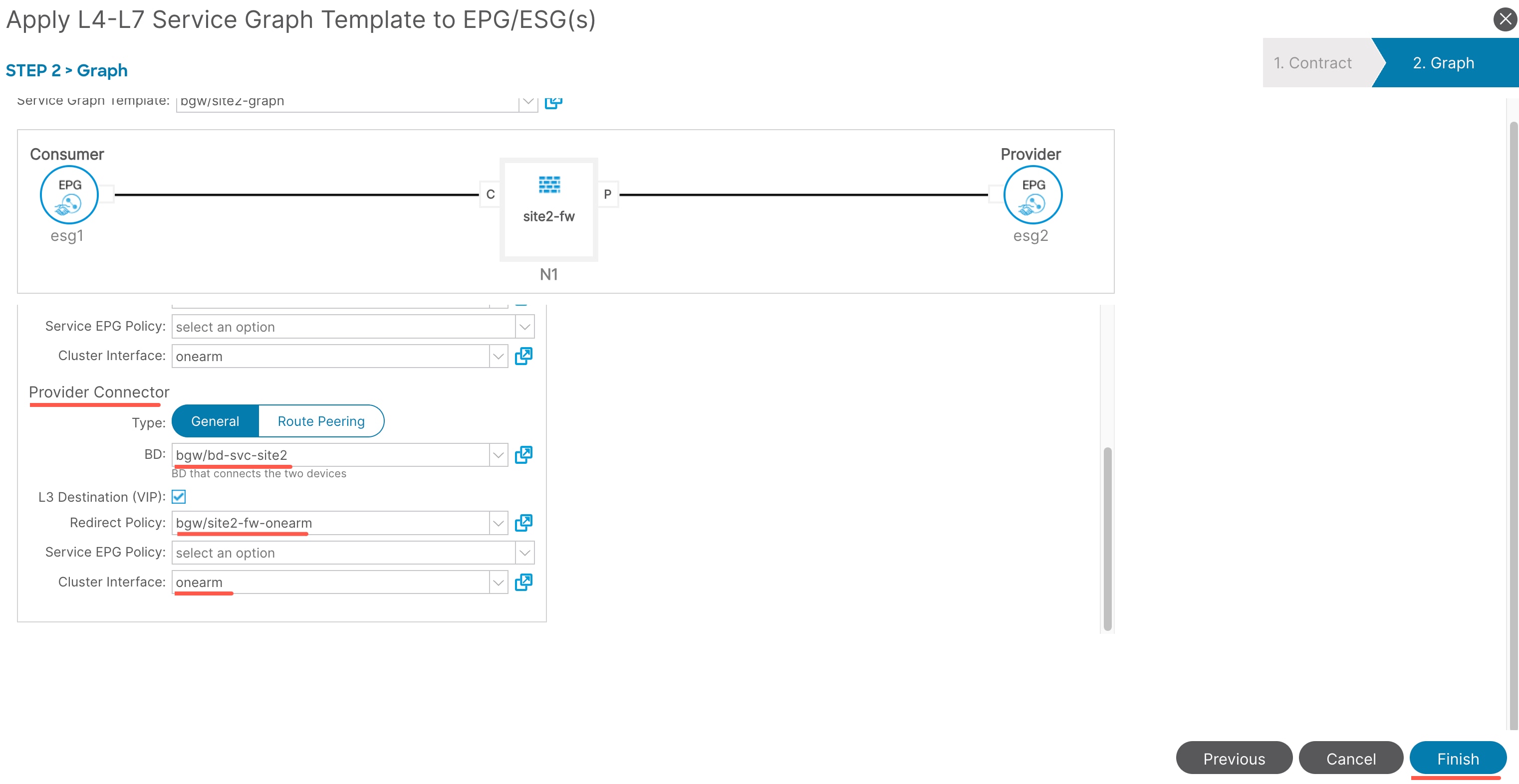
Figure 485. ACI Site 2 Deployed Graph Instance
Data Plane and Policy Verification
This section focuses on the verification process only for ACI Site 1 as the same principles apply to both ACI sites. The following figure illustrates the topology.
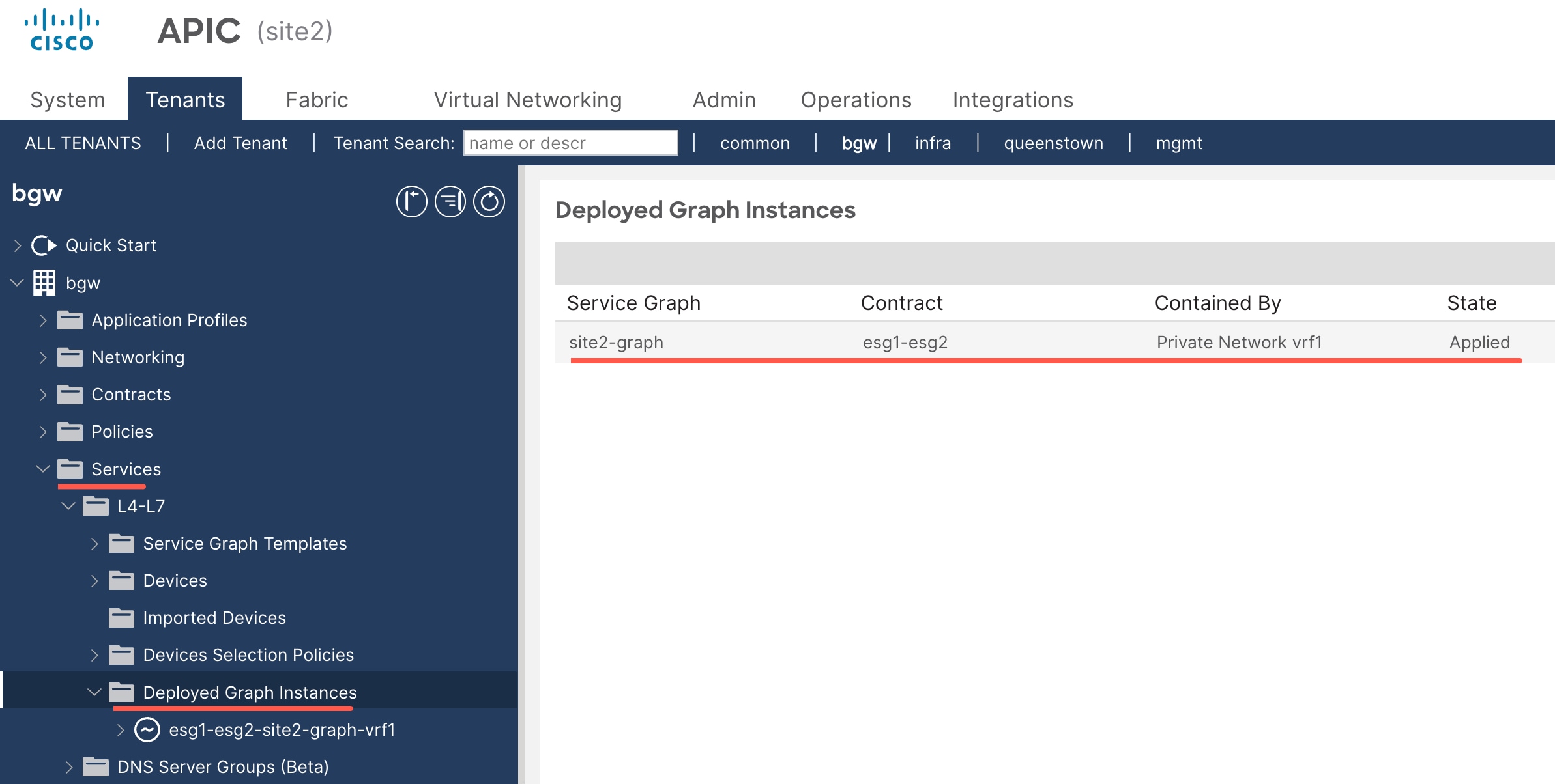
Figure 486. Firewall insertion topology example
The initial verification step is to confirm that the deployed graph instance is in “Applied” state without any faults.
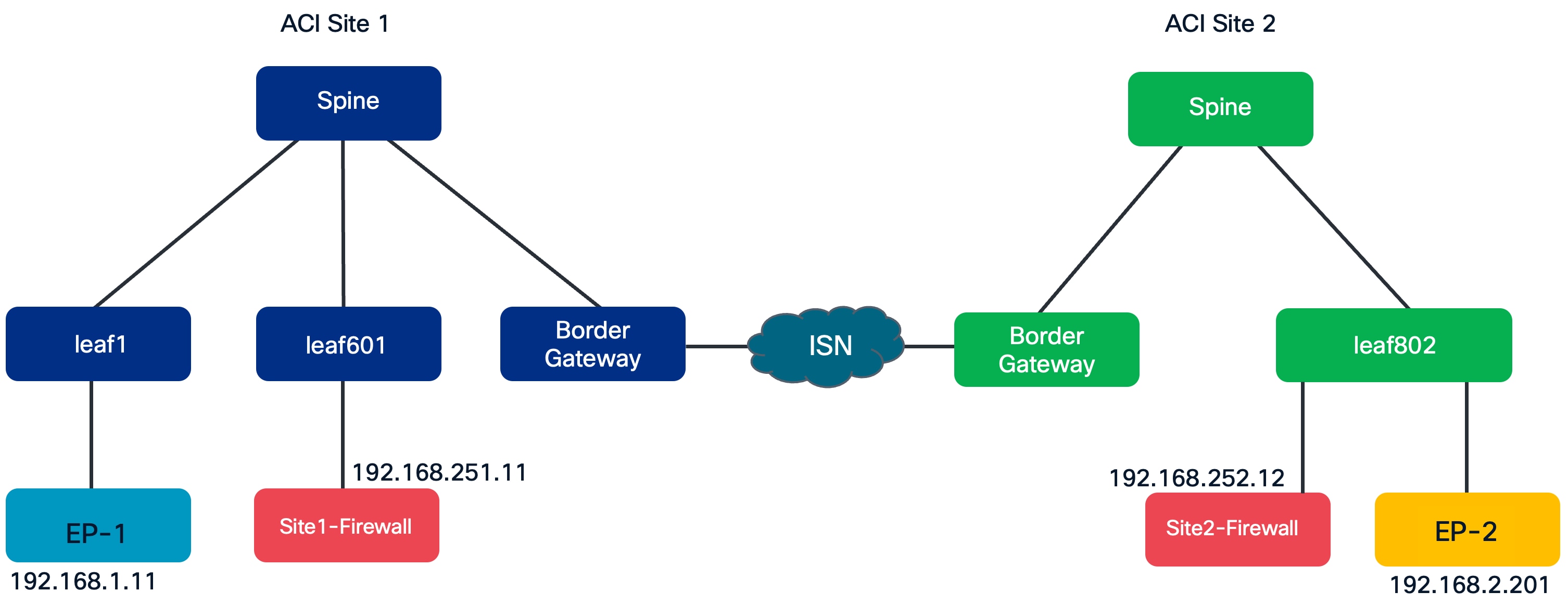
Figure 487. Deploy Graph Instance in Applied state without any faults
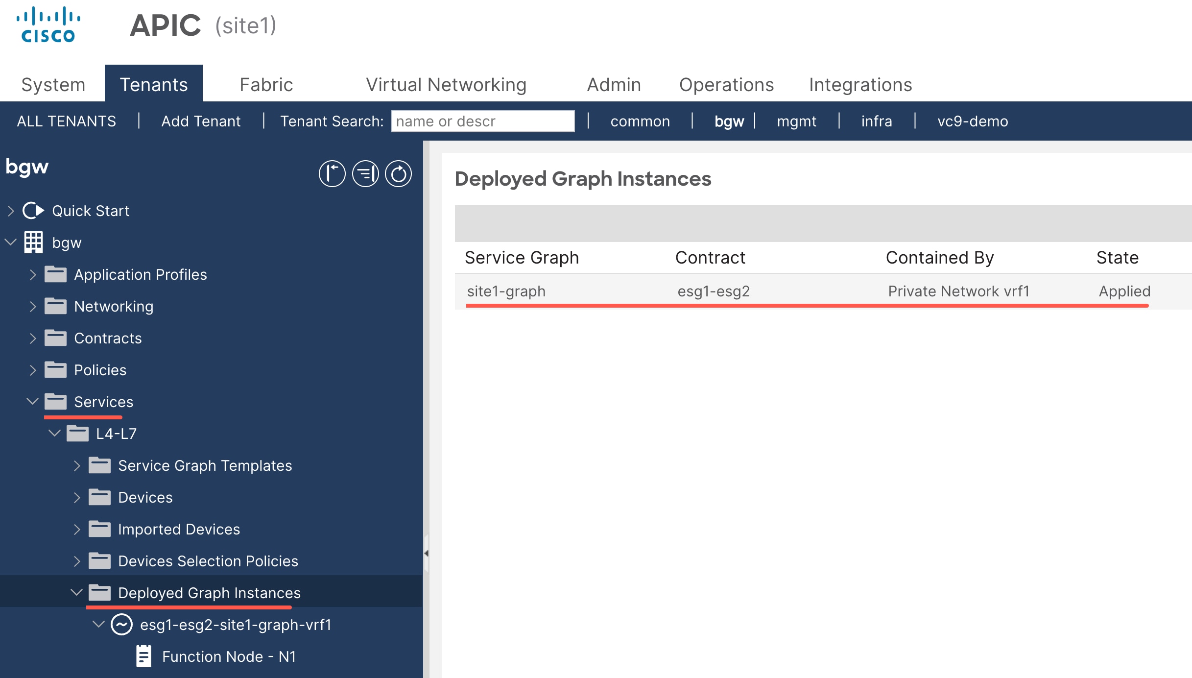
Figure 488. Deployed graph instance without faults
The pcTag (class ID) of the service node connector can be verified under the Deployed Graph Instance. Since the service node uses a one-arm interface, both the consumer and provider connectors use the same class ID. In this example, VLAN 240 is programmed on the ACI leaf interface that connects to the service node that is a virtual firewall running on top of a VMM domain integrated with ACI, and the VLAN is automatically programmed by the APIC. However, if the service node resides in a physical domain, the VLAN must be statically configured as part of the L4-L7 device configuration.
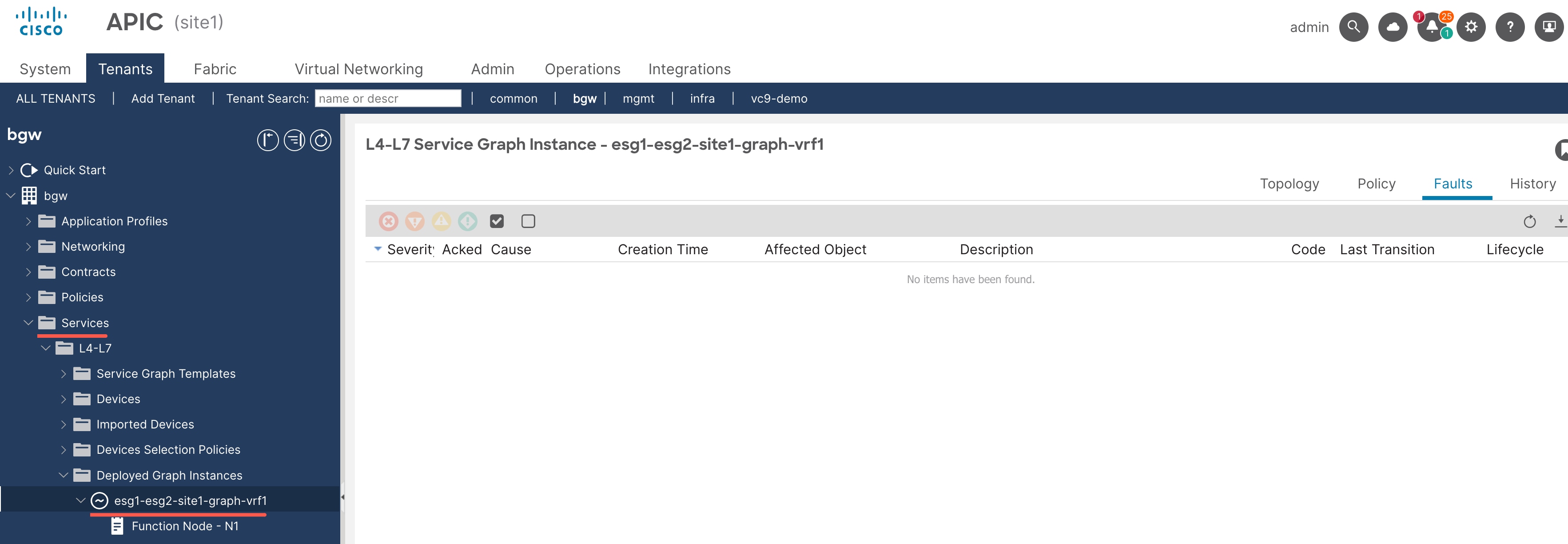
Figure 489. ACI Site 1 Service Node connector class ID
Verify that the contract subject within the contract “esg1-esg2” has the right L4-L7 Service Graph attached.
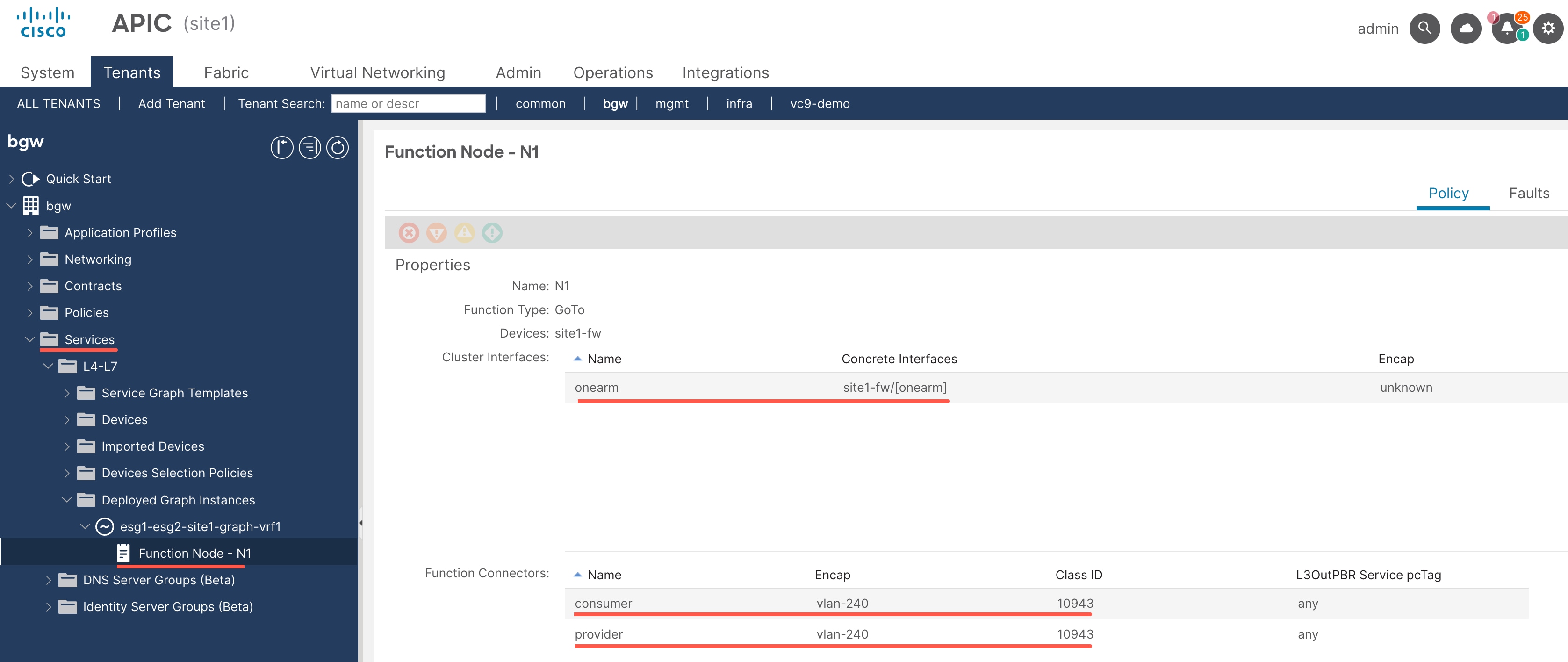
Figure 490. ACI Site 1 Contract subject with service graph attached
Verify that the redirect zoning rules are programmed on the leaf switches to which the consumer or the provider endpoints are attached. In this example, 2162688 is the VRF vrf1 VNID, ESG esg1 class ID is 10947 and ESG esg2 class ID is 10948. Although the figure below shows the result for one direction from 10947 to 10948, a zoning-rule for the return direction, from 10948 to 10947, should also exist.
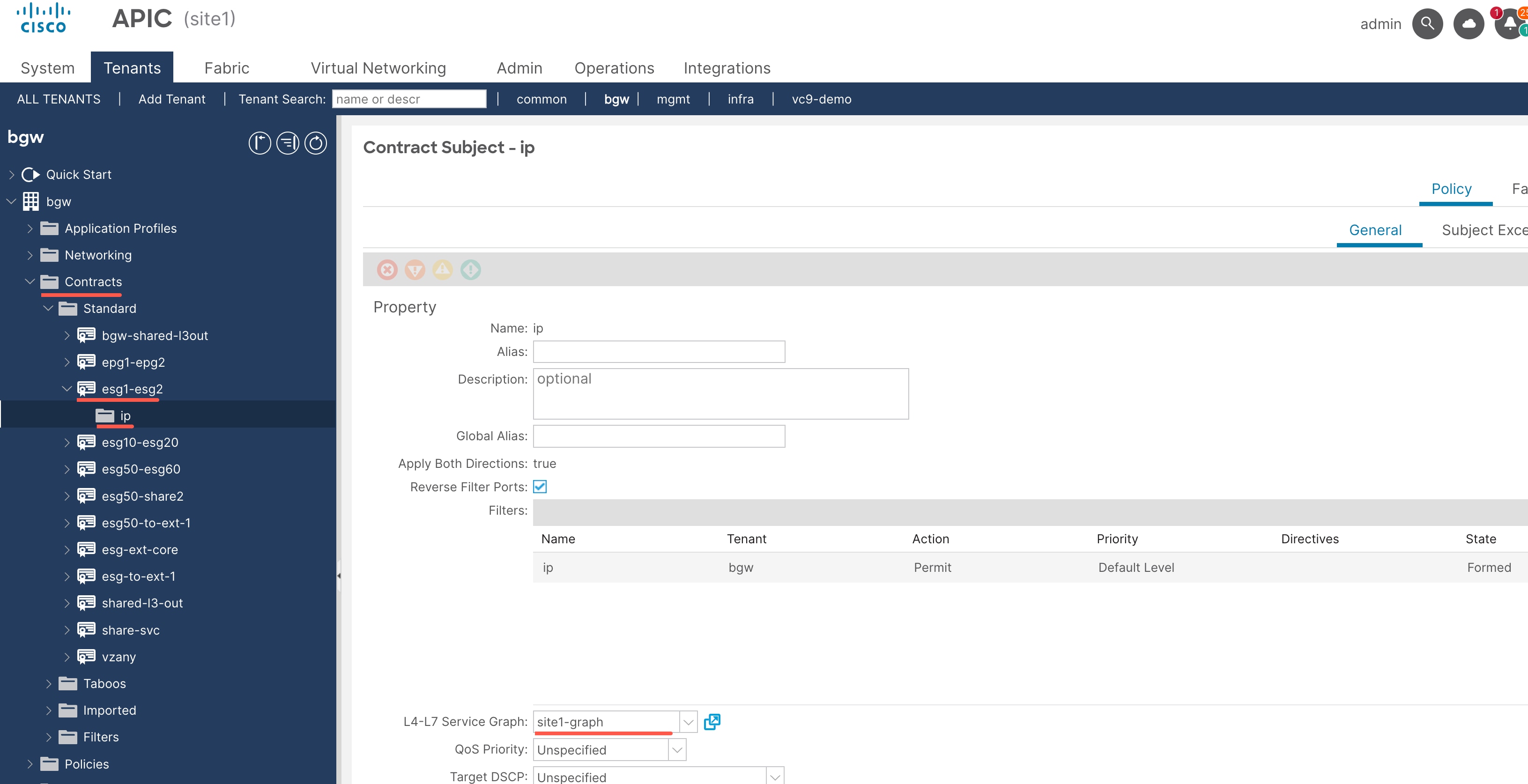
Figure 491. ACI Site 1 Border Gateway zoning-rule with redirect action
In this example, 192.168.251.11 is the Service Node (Firewall) one-arm interface IP address. Verify that the “operSt” is “enabled”. Note that for inter-site traffic, the Border Gateway is responsible for the policy enforcement. Thus, the zoning-rule and reachability verification should be performed on the Border Gateway switches.

Figure 492. Service redirect on Border Gateway
481To verify the data plane behavior, initiate ICMP traffic from endpoint 192.168.1.11 (ESG: esg1) in ACI Site 1 to endpoint 192.168.2.201 (ESG: esg2) in ACI Site 2. The expected behavior is that the traffic will be steered through the firewall.

Figure 493. Sending ICMP from 192.168.1.11 to 192.168.2.201
The capture command below is specific to Cisco ASA platforms; syntax for other firewall models may vary. In this example, the firewall is configured with a one-arm interface named “onearm”. As show in the Figure below, traffic is redirected to Site1-Firewall.
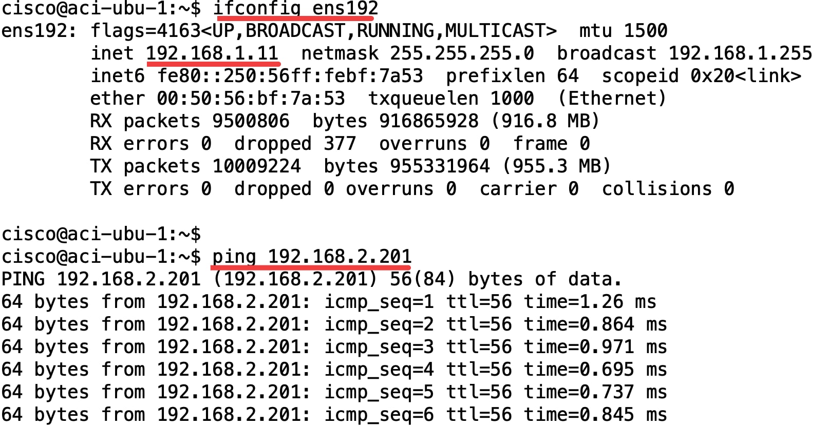
Figure 494. Site 1 Firewall sees traffic in and out
In the Site 1 firewall capture output above, 192.168.251.254 is the service BD SVI that ACI Site 1 uses as the source IP to send continuous ICMP health probes to the firewall at 192.168.254.11, based on the intervals defined in the IP SLA Monitoring Policy.
Since the service graph is also applied in ACI Site 2, traffic is redirected to the Site2 firewall by Site 2 Border Gateway, as demonstrated in the captured traffic below:
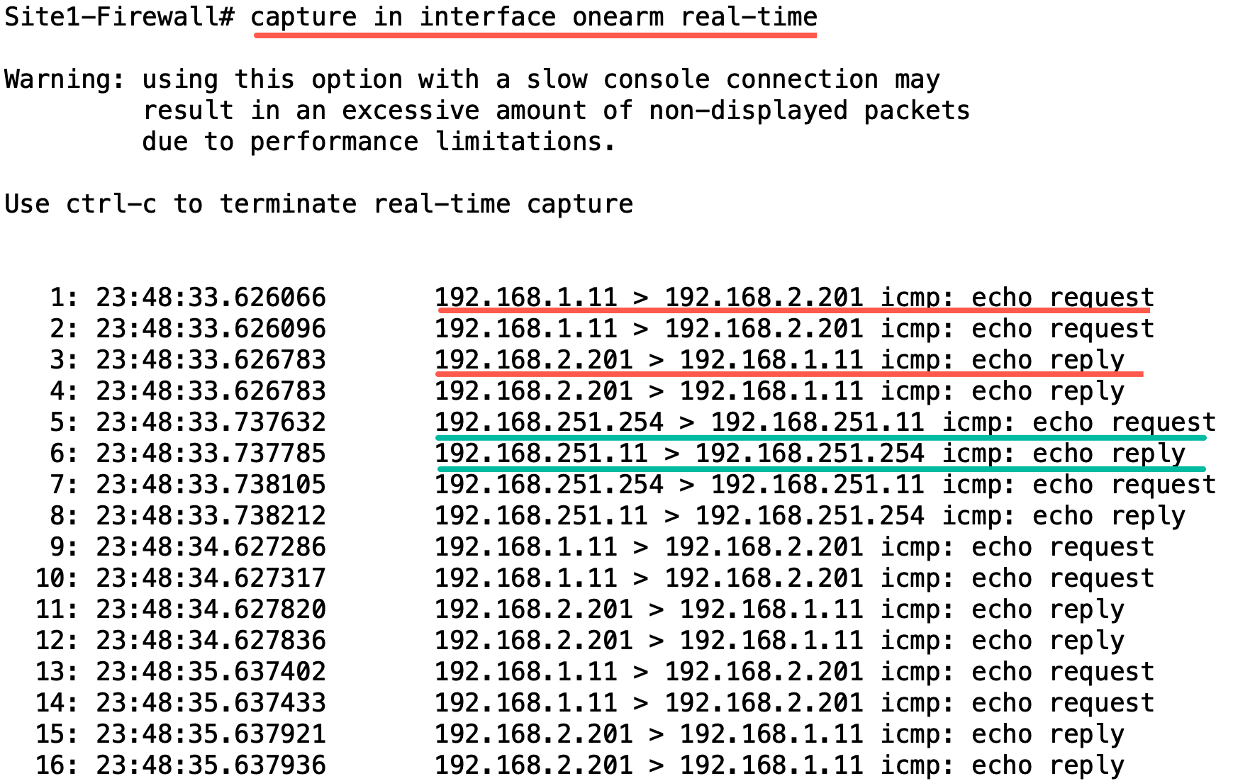
Figure 495. Site 2 Firewall sees traffic in and out
In the Site 2 firewall capture output above, 192.168.252.254 is the service BD SVI that ACI Site 2 uses as the source IP to send continuous ICMP health probes to the firewall at 192.168.252.12, based on the intervals defined in the IP SLA Monitoring Policy.
A. At the time of writing up to ACI release 6.2(2), Border Gateway must be a dedicated device, you cannot connect endpoints like server, router to a Border Gateway. The requirement maybe relaxed in the future ACI release.
Q. Can I connect Border Gateways from ACI Site 1 directly to Border Gateways in ACI Site 2 using back-to-back connections?
A. No, it is not supported to use back-to-back connections, the ISN is required to interconnect Border Gateways across site. The requirement maybe relaxed in the future ACI release.
Q. Can I just use EPGs instead of ESGs?
A. No, it is required to use ESGs when extending a logical construct between ACI sites using Border Gateways. ESGs must be used for security group classification for policy enforcement whereas EPGs are used to enable the VLANs on the downlinks for endpoint connectivity.
Q. Is it mandatory to use the same ACI version between two ACI sites?
A. No, there is no version dependency between two ACI Sites.
Q. Can I share an ISN device with other networking functions?
A. Yes, you can share an ISN device with other networking functions. However, it is recommended to use a dedicated VRF for the Inter-Site function between ACI Border Gateways across sites.
Q. If I do not need intra-subnet communication across sites, and all communication is inter-subnet; do I need to stretch the BD across sites?
A. No, you do not need to stretch the BD in this scenario, local BDs should be deployed also on the site’s BGWs to ensure EVPN Type-2 prefixes are advertised toward the remote sites.
Q. Can I use vzAny contract instead of specific contract?
A. Yes, you can use vzAny just like in a single ACI site; it represents all ESGs in a VRF and simplifies contract application across multiple sites.
Q. Does the solution support inter-tenant communication?
A. Yes, inter-tenant communication is supported. The use cases for intra-tenant inter-VRF communication are similarly supported in inter-tenant scenarios, enabling flexible policy enforcement and connectivity across tenants.
● Cisco Nexus One Architecture White Paper
● Deploying and Verifying Cisco Nexus One Fabric Connectivity and Policy between ACI and NXOS Fabrics
◦ https://www.cisco.com/c/en/us/td/docs/dcn/whitepapers/cisco-nexus-one-deployment-guide-aci-nxos.html