Building AI/ML Data Center Fabric using VXLAN EVPN for GPUaaS
Available Languages
Bias-Free Language
The documentation set for this product strives to use bias-free language. For the purposes of this documentation set, bias-free is defined as language that does not imply discrimination based on age, disability, gender, racial identity, ethnic identity, sexual orientation, socioeconomic status, and intersectionality. Exceptions may be present in the documentation due to language that is hardcoded in the user interfaces of the product software, language used based on RFP documentation, or language that is used by a referenced third-party product. Learn more about how Cisco is using Inclusive Language.
- US/Canada 800-553-2447
- Worldwide Support Phone Numbers
- All Tools
 Feedback
 Feedback
Design Concept and Customer Use Case
High Performance and Scalability
Network Segmentation and Security
Building a Non-Blocking, Rail-Optimized Network for AI/ML
Components used in this scenario
Cisco Nexus 9364D-GX2A Overview
Slice Pair Architecture and Buffering
Benefits for AI/ML and Data Center Fabrics
Non-Blocking, Line-Rate Design
Deep Buffers for Lossless Networks
Cable Matrix and Buffer Optimization on Cisco Nexus 9364D-GX2A
Leaf Port Allocation per Slice
Step-by-Step Configuration using Cisco Nexus Dashboard
Use Case: Multi-Tenant GPU-as-a-Service (GPUaaS) with Cisco VXLAN EVPN Fabric
Network Segmentation and Provisioning
Advanced Telemetry and L3 Segmentation
Monitoring Intelligent AI/ML Infrastructure with Cisco Nexus Dashboard
The rapid growth of Artificial Intelligence (AI) and Machine Learning (ML) workloads is transforming modern data centers, driving an unprecedented demand for scalable, high-performance, and flexible network architectures. Organizations deploying large-scale GPU clusters for AI/ML training and inference require a robust networking foundation that can deliver low latency, high bandwidth, and operational simplicity.
This document presents a design guide for building data center networks for AI/ML use-cases, leveraging Cisco Nexus 9000 Series switches and VXLAN EVPN fabric. The blueprint is based on a real-world deployment of Cisco UCS-C885A-M8-H26 Dense GPU Servers (with NVIDIA GPUs) connected to VXLAN fabric which is built using Nexus 9300 Series ToR switches and orchestrated by Cisco Unified Nexus Dashboard.
By integrating VXLAN EVPN, this architecture delivers a highly scalable, multi-tenant, and programmable network fabric, optimized for the performance and agility requirements of AI/ML clusters. VXLAN EVPN fabric supports seamless east-west traffic flow, workload mobility and network segmentation providing solid foundation for current and future AI/ML initiatives.
Design Concept and Customer Use Case
The proposed network, providing the following benefits for AI/ML data center deployments:
High Performance and Scalability
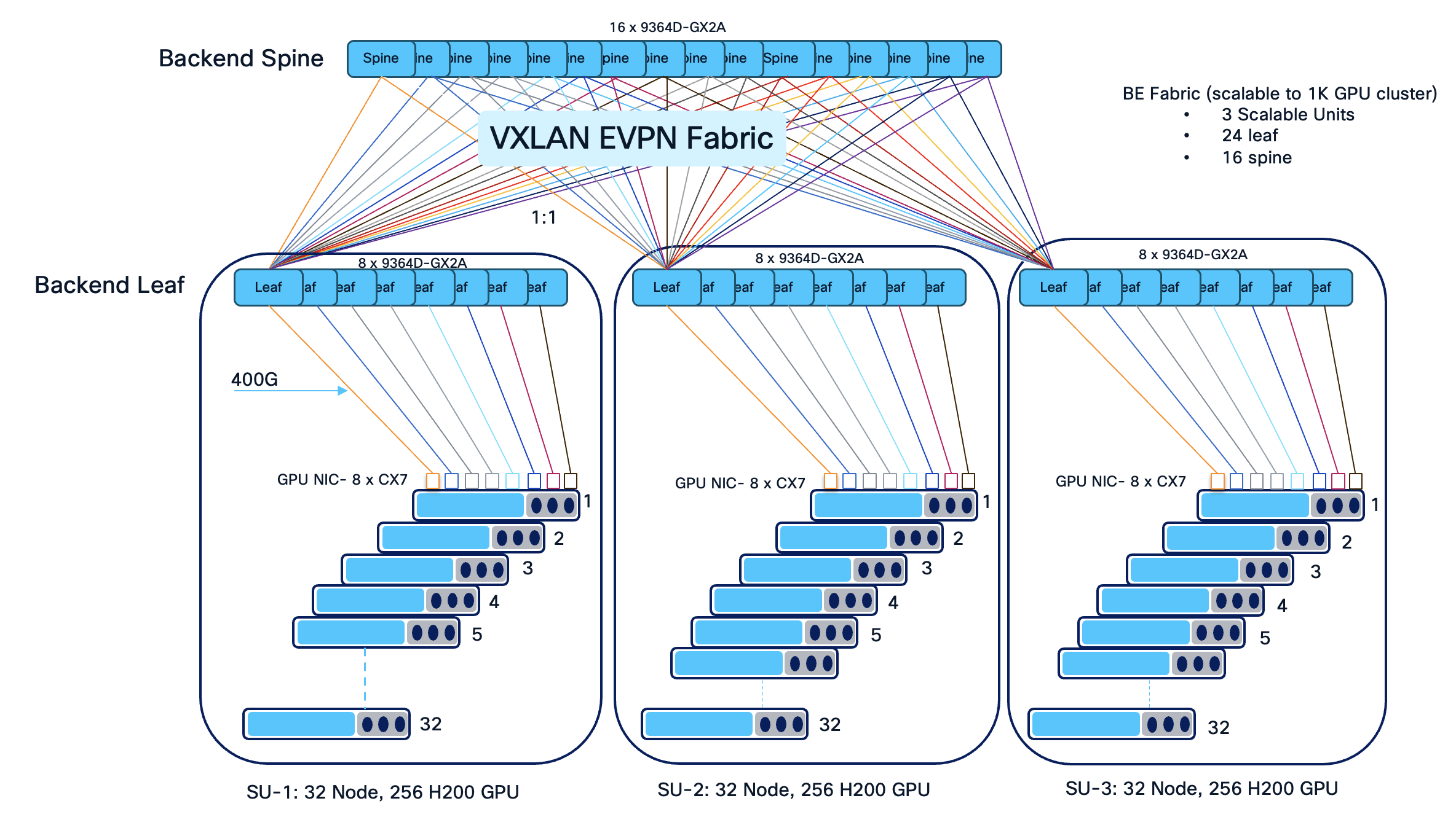
The architecture supports dense GPU clusters and high-throughput east-west traffic, essential for AI/ML training workloads. The use of 16 spines and 24 leaves ensures non-blocking bandwidth and flexible scale-out up to 4 scalable unit (SU) as the cluster grows.
A Scalable Unit (SU) is a standardized building block of infrastructure—combining a specific number of GPUs — designed to be replicated to grow an AI cluster. In this scenario, we have 32 GPU servers per scalable unit with 8 leaves. Grouping leaves in sets of eight aligns with rail-optimized cabling, ensures non-blocking bandwidth for high-density GPU workloads, and enables seamless expansion as additional servers are added to the AI cluster.
Deploying 16 spine and 24 leaf switches for 96 NVIDIA GPU servers is a deliberate design choice to achieve a high-performance, non-blocking, and 3 scalable fabric optimized for AI/ML workloads. This topology allows the infrastructure to be neatly divided into scalable units, simplifying cable management and enabling straightforward expansion by adding leaves and spines as the cluster grows.
With 24 leaves, GPU-to-leaf and uplink distribution can be optimized for and minimal latency, aligning with the physical and logical layout of modern GPU clusters.
A rail-optimized topology is a high-performance AI data center network design that connects identical GPU positions across different servers (e.g., GPU 0 to GPU 0) to the same leaf switches, forming dedicated "rails". This approach minimizes network hops, reduces latency, and maximizes bandwidth for AI training by ensuring parallel communication, such as NCCL, stays within optimized paths.
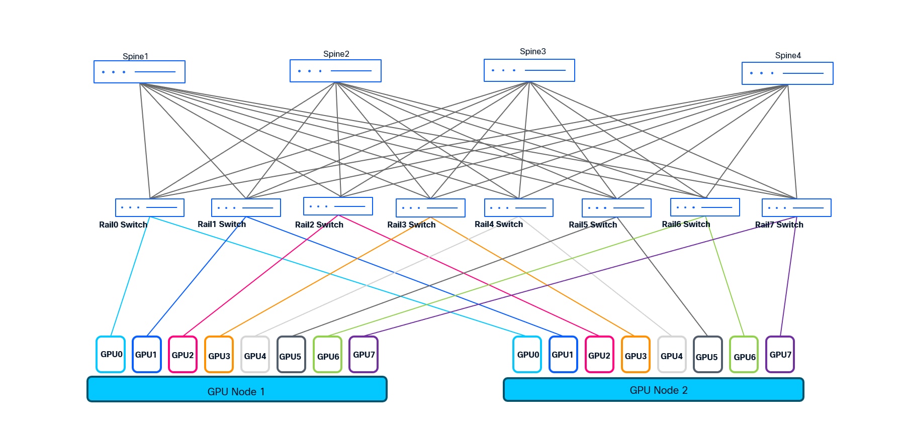
We choose rail-optimized design for the customer to deliver ultra-low latency, non-blocking connectivity, and operational efficiency for large-scale AI/ML clusters. It enables easy scaling, streamlined troubleshooting, and maximizes the performance of distributed GPU workloads.
Operational Simplicity and Automation: Leveraging Cisco Unified Nexus Dashboard 4.1 enables intent-based fabric provisioning, automated lifecycle management, and unified visibility, reducing operational complexity and human error. From the various data center fabric templates supported by Cisco Unified Nexus Dashboard, eBGP Routed fabric and VXLAN EVPN fabric template are most suitable for building AI/ML fabrics. In this scenario we have used VXLAN EVPN fabric template to support multi-tenancy.
Network Segmentation and Security
VXLAN EVPN allows for logical segmentation of workloads, facilitating secure multi-tenancy and policy-driven traffic management.
This design accommodates advancements in AI/ML infrastructure, including faster interconnects (e.g., 400G), additional GPU servers, and integration with hybrid/multi-cloud environments.
A leading enterprise deployed a next-generation AI/ML data center leveraging 88 NVIDIA GPU servers (Cisco UCS-C885A-M8-H26) and scalable up to 96 GPU servers (each UCS server houses 8 GPUs which gives the total of 768 GPUs) to accelerate deep learning and analytics workloads. To meet their requirements for high throughput, low latency, and seamless scalability, the customer implemented VXLAN EVPN fabric (spine-leaf architecture) using Cisco Nexus 9300 series ToR switches which is orchestrated and managed by Unified Nexus Dashboard 4.1.
Consistent Performance: The network delivered predictable, line-rate bandwidth for distributed AI/ML workloads, minimizing job completion times.
Agile Operations: Automated deployment and monitoring via Nexus Dashboard streamlined operations and reduced provisioning time from days to hours.
Secure Multi-Tenancy: VXLAN EVPN enabled the enterprise to securely segment research, production, and development environments within the same physical infrastructure.
This design blueprint empowers organizations to confidently deploy scalable, efficient, and secure AI/ML data center networks leveraging Cisco best practices.
VXLAN EVPN - VXLAN EVPN provides scalable, multi-tenant Layer 2/3 network virtualization using an Ethernet VPN (EVPN) control plane, enabling flexible workload mobility and efficient traffic engineering across spine-leaf data center fabric.
Rail Optimized Design - Rail optimized design refers to network architectures that align leaf-spine connectivity and cabling with server racks (“rails”), minimizing hop count and maximizing bandwidth for AI/ML clusters, ensuring efficient and deterministic communication paths.
QoS (Quality of Service) - QoS ensures optimal performance for AI/ML and other critical workloads by prioritizing traffic, managing bandwidth allocation, and preventing resource starvation, supporting a predictable and efficient network environment.
RoCEv2 - RoCEv2 (RDMA over Converged Ethernet version 2) enables low-latency, high-throughput data transfer for AI/ML workloads by allowing direct memory access over standard IP-based Ethernet networks, crucial for distributed GPU clusters.
PFC (Priority Flow Control) - Priority Flow Control (PFC) is used to signal the congestion by using pause frames and pause mechanism. With the help of PFC, the device experiencing congestion notifies the upstream devices to slow down which in turn starts buffering the traffic.
ECN (Explicit Congestion Notification) - ECN enables network devices to signal impending congestion to endpoints without dropping packets, allowing intelligent traffic management and minimizing latency spikes for sensitive AI/ML flows.
Both PFC and ECN in conjunction transforms ethernet from lossy to lossless network and make it suitable for Storage and AI/ML use-cases.
CNP (Congestion Notification Packet) - CNP is a mechanism in RoCEv2 networks where switches send congestion notification packets to endpoints, prompting them to reduce transmission rates and alleviate network congestion proactively.
Cisco Intelligent Packet Flow - Cisco Intelligent Packet Flow provides advanced load-balancing to optimize traffic distribution across the fabric, utilizes hardware-accelerated telemetry for real-time visibility, and supports fault-aware recovery to ensure resilient and uninterrupted AI/ML data flows.
The Cisco Intelligent Packet Flow framework is built on four key pillars:
● Advanced Load-BalancingAdvanced Load-Balancing - Dynamically distributes traffic flows across all available paths (ECMPs) to optimize bandwidth utilization and minimize congestion.
● Hardware-Accelerated TelemetryHardware-Accelerated Telemetry - Provides real-time, granular visibility into packet flows and network health, leveraging on-switch analytics for rapid detection of hotspots and anomalies.
● Fault-Aware RecoveryFault-Aware Recovery - Quickly identifies and reroutes around network faults or degraded links, ensuring uninterrupted data delivery and high availability.
● Congestion ManagementCongestion Management - Proactively detects congestion points and applies techniques like PFC and ECN to maintain lossless and low-latency operation, critical for latency-sensitive AI/ML workloads.
Building a Non-Blocking, Rail-Optimized Network for AI/ML
For the design illustrated in this design, we implement a scalable, two-tier, spine-leaf architecture to deliver the ultra-low latency and massive bandwidth required for AI/ML workloads. This network is engineered to support 96 GPU servers, each equipped with 8 NVIDIA GPUs and capable of 400 Gbps per GPU, resulting in exceptionally demanding east-west traffic patterns.
To provide both scalability and operational modularity, the network is organized into three scalable units, each comprising 8 leaf switches. Each scalable unit interconnects with 32 servers, except for the final unit, which connects to 24 servers and scalable to 32 servers. Each leaf switch is responsible for connecting to 32 GPUs, following a rail-optimized design: for example, Leaf 1 connects to GPU0 of 32 different servers, Leaf 2 to GPU1 of those servers, and so forth through Leaf 8. This approach is repeated for each scalable unit, maximizing cabling efficiency and ensuring deterministic, high-bandwidth paths between GPUs and across the fabric.
In total, the fabric consists of 24 leaves switches and 16 spine switches. Every leaf switch is equipped with 32 uplinks, creating a fully non-blocking architecture and providing line-rate bandwidth from each server-facing port through to the spine layer. Each leaf uplinks to every spine with 2x400G links, ensuring both high throughput and non-blocking line rate. This dense interconnection enables any-to-any communication across the GPU cluster at full 400 Gbps line rate per server, which is essential for distributed AI/ML training jobs.
This modular, rail-optimized topology not only delivers the required bandwidth and deterministic latency for GPU workloads, but also provides the flexibility to scale out by adding additional scalable units (sets of leaf switches and servers). The design ensures that there are also available ports for connecting storage devices, storage clusters, or for integrating with other segments of the enterprise network, without compromising the non-blocking characteristics of the fabric.
This architecture, leveraging Cisco Nexus 9364D-GX2A leaf switches and managed by Cisco Nexus Dashboard 4.1, creates a robust foundation for current and future AI/ML workloads, supporting high performance, operational simplicity, and seamless scalability.
Components used in this scenario
Table 1. List of Hardware and Software Version
| Hardware |
Role |
Quantity |
Software |
| Nexus 9364D-GX2A |
Spine |
16 |
NX-OS 10.5(3)F |
| Nexus 9364D-GX2A |
Leaf |
24 |
NX-OS 10.5(3)F |
| vND |
Unified Nexus Dashboard |
1 (3 node cluster) |
4.1.1g |
| UCS-C885A-M8-H26 |
Nvidia H200 SXM GPU server |
88 |
- |
Cisco Nexus 9364D-GX2A Overview
The Cisco Nexus 9364D-GX2A is a high-performance, high-density 2RU fixed switch purpose-built for next-generation data center deployments, including large-scale AI/ML, HPC, and cloud environments. It is part of the Cisco Nexus 9000 Series and is engineered to deliver line-rate throughput, ultra-low latency, and advanced telemetry and automation capabilities.
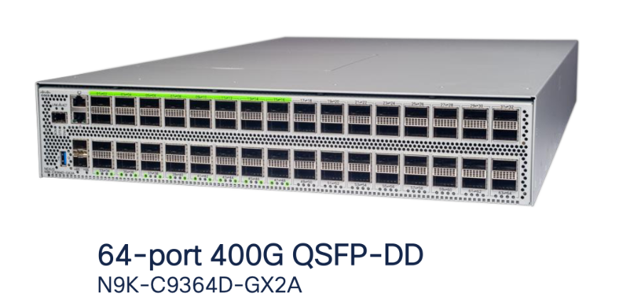
Ports: 64x400-Gigabit Ethernet QSFP-DD, supporting flexible breakouts (including 4x100G and 2x200G per port).
Switching Capacity: Up to 25.6 Tbps with line-rate performance across all ports.
Form Factor: 2RU with redundant, hot-swappable power supplies and fans.
Software: Runs Cisco NX-OS, supporting VXLAN EVPN, RoCEv2, PFC, hardware-accelerated telemetry, and advanced automation.
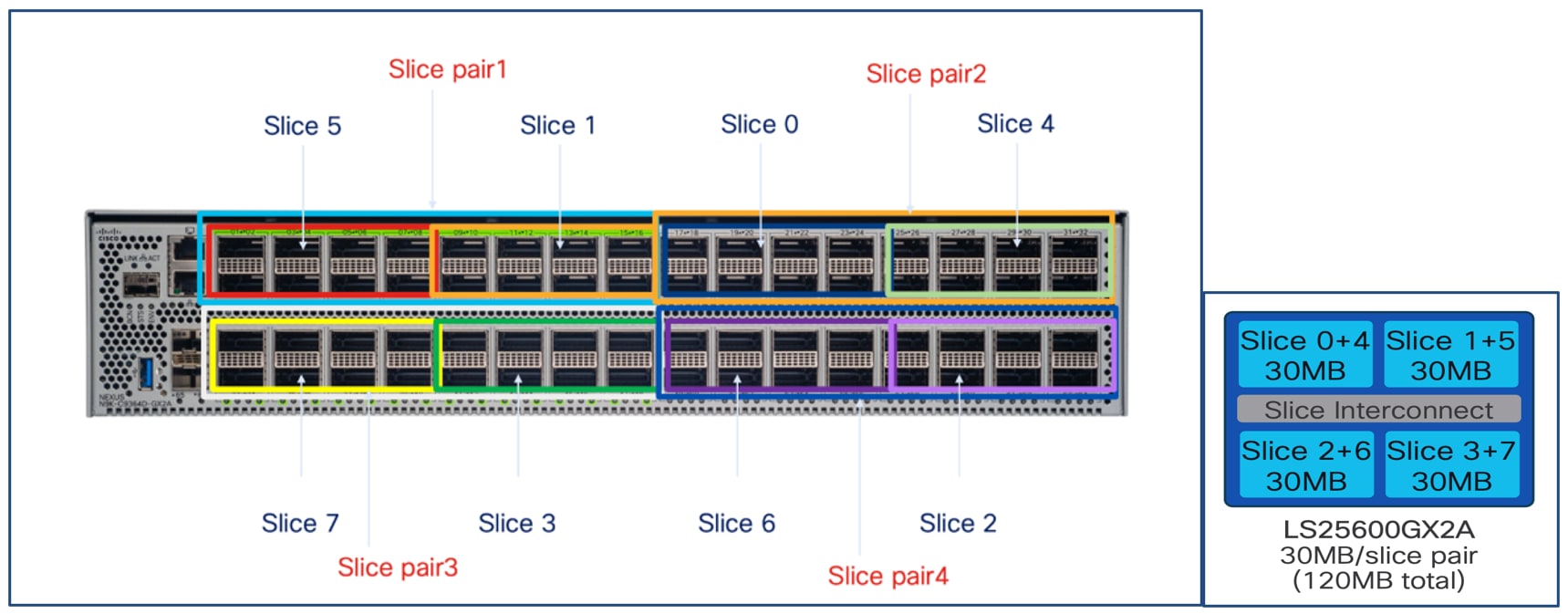
Slice Pair Architecture and Buffering
The Nexus 9364D-GX2A is built on SoC (Switch on Chip) ASIC architecture:
Number of Slice Pairs: 4
Total Slices: 8 (2 slices per pair)
Ports per Slice Pair: 16x400G
Buffer per Slice Pair: 30 MB
Total Buffer: 120 MB (30 MB x 4 slice pairs)
Each slice pair’s buffer is essential for absorbing traffic microbursts and supporting lossless transport such as RoCEv2 with PFC—vital for AI/ML workloads that demand high throughput and minimal congestion loss.
Benefits for AI/ML and Data Center Fabrics
Non-Blocking, Line-Rate Design
All 64 ports operate at full 400G line rate, supporting non-blocking architectures for large-scale GPU clusters and storage fabrics.
The 16-port-per-slice-pair design aligns well with rail-optimized GPU cluster cabling, ensuring predictable, low-latency data flows.
Deep Buffers for Lossless Networks
Sufficient buffering per slice pair to prevent drops during short-term congestion, maintaining performance in RoCEv2, PFC, and other critical data paths.
Cable Matrix and Buffer Optimization on Cisco Nexus 9364D-GX2A
To optimize buffer utilization and ensure a balanced load across the Cisco Nexus 9364D-GX2A switch, a structured cable matrix is used for both spine-to-leaf uplinks and GPU-to-leaf downlinks.
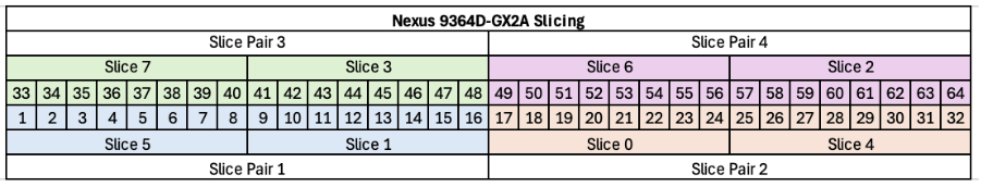
Leaf Port Allocation per Slice
Each slice of the 9364D-GX2A consists of 8 ports.
Ports 1–4 of each slice are dedicated to GPU server (downlink) connections.
Ports 5–8 of each slice are used for uplinks to the spine switches.
Each leaf switch is equipped with two uplinks per spine, ensuring a non-blocking fabric.
Uplink ports are distributed across all slices for optimal buffer usage and fairness.
For example, Leaf1 uplinks to Spine1 via Slice5 Port1 and Slice7 Port33.
Leaf2 uplinks to spines using Slice1 Port9 and Slice3 Port41.
This pattern continues for all leaves, distributing connections evenly across slices and spines.
GPU0 of servers in Scalable Unit 1 (SU1) connects to Leaf1 with a round-robin mapping to front-panel ports:
Table 2. GPU to Switch Cable Matrix
| GPU Index |
Switch Port |
| Server1 GPU0 |
Port1 |
| Server2 GPU0 |
Port2 |
| Server3 GPU0 |
Port3 |
| Server4 GPU0 |
Port4 |
| Server5 GPU0 |
Port9 |
| Server6 GPU0 |
Port10 |
| Server7 GPU0 |
Port11 |
| Server8 GPU0 |
Port12 |
This pattern is repeated for subsequent servers and GPUs, ensuring even usage of all available ports and associated buffers.
By structuring both uplink and downlink connections in this manner, the design maximizes the switch’s buffer efficiency, supports deterministic low-latency traffic flows, and maintains a fully non-blocking, high-performance network fabric for large-scale AI/ML deployments.
Step-by-step Configuration using Cisco Nexus Dashboard
Deploying and managing a high-performance, non-blocking AI/ML data center fabric requires both robust design and efficient operational tools. Cisco Nexus Dashboard delivers intent-based automation, centralized management, and end-to-end visibility for VXLAN EVPN fabrics—making it the ideal solution for deploying, monitoring, and scaling modern data center networks.
This section provides a detailed, step-by-step guide to configuring your AI/ML-optimized spine-leaf fabric using Cisco Nexus Dashboard. The workflow is tailored to the rail-optimized, non-blocking design described in earlier sections and demonstrates how to:
● Define and onboard Nexus 9000 switches into Nexus Dashboard.
● Create and configure a VXLAN EVPN fabric.
● Automate underlay and overlay network provisioning, including BGP, loopback addressing, and VLAN assignments.
● Configure advanced features such as PFC, QoS, and DLB, all through the Nexus Dashboard interface.
Ensure all Nexus 9000 series switches (spines and leaves) are powered on, reachable via management (OOB as well as inband mgmt is supported), and running a supported NX-OS version.
Nexus Dashboard is installed and operational with proper IP reachability to all switches.
Have a logical design ready (IP addressing, ASN, VLANs, VRFs, etc.).
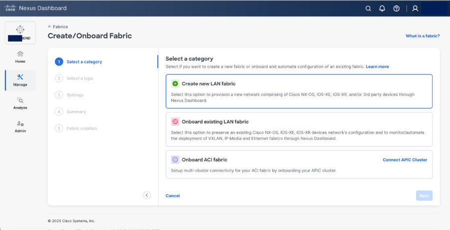
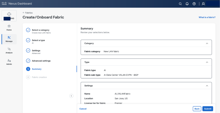
Step 1. Create a new fabric.
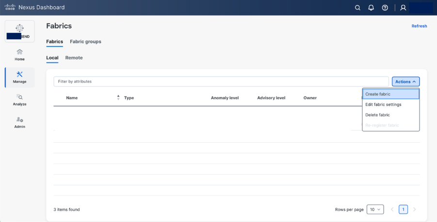
Step 2. Select Create fabric.
Step 3. Select AI > AI VXLAN EVPN fabric type.
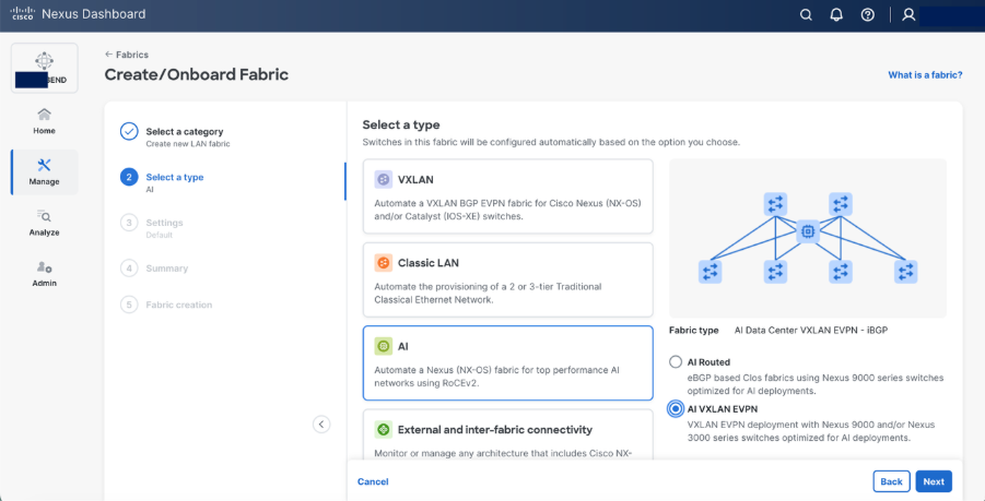
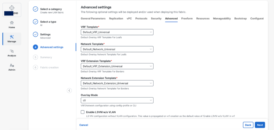
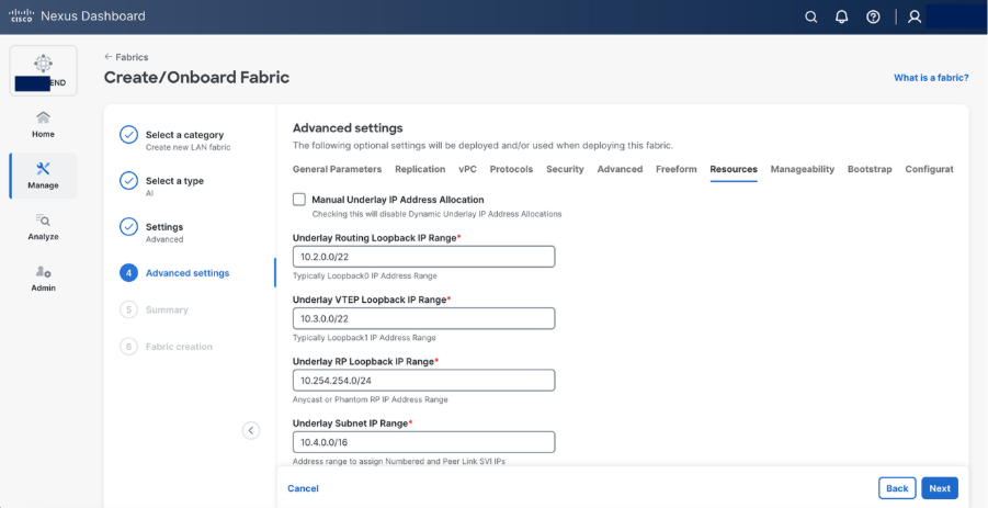
Step 4. Set the basic parameters.
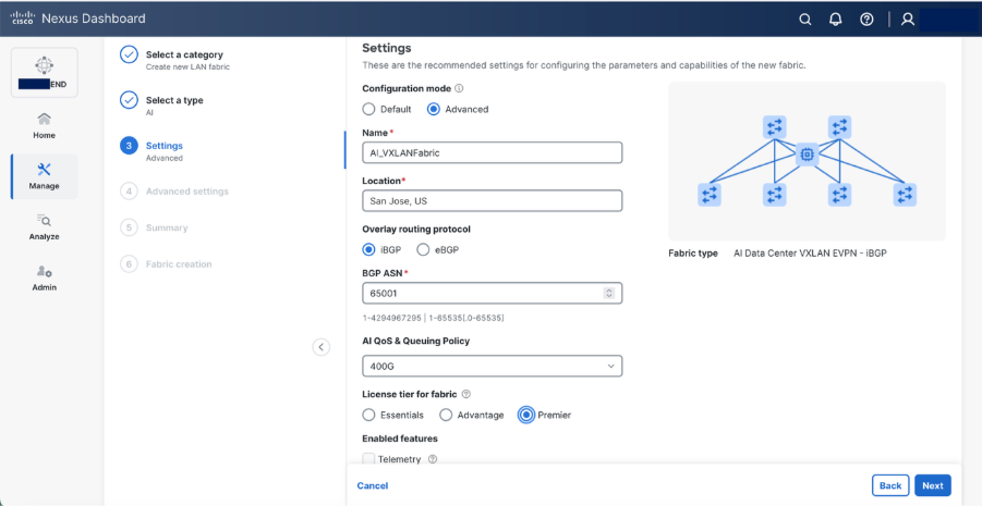
Select Advanced configuration mode to customize the resources and templates.
● Specify a name for fabric. Provide the location
● Select iBGP as Overlay Routing Protocol
● Provide a BGP ASN
● Select 400G AI QoS & Queuing Policy, N9364-DGX2A supports 400Gbps.
Note: Edit the existing 400G AI QoS & Queuing template in template library to reflect as given below (These values are based on specific given scenario, you may want to change based on your requirements and Best Job Completion Time (JCT))
class type queuing c-out-8q-q3
bandwidth remaining percent 95 >>> as the network is dedicated for GPU fabric, allocate maximum bandwidth
random-detect minimum-threshold 150 kbytes maximum-threshold 7000 kbytes drop-probability 7 weight 12 ecn
class type queuing c-out-8q-q-default
bandwidth remaining percent 5 >>> for control traffic
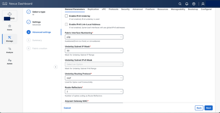
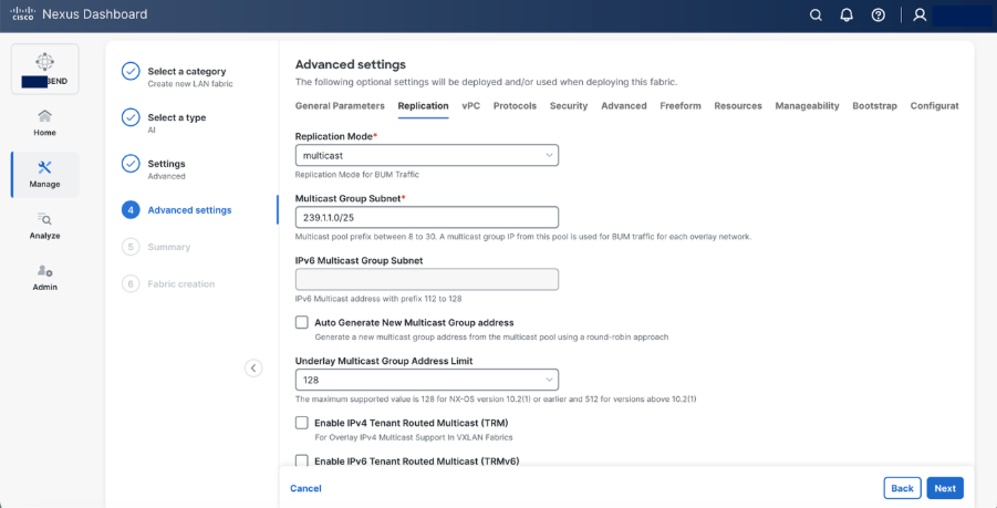
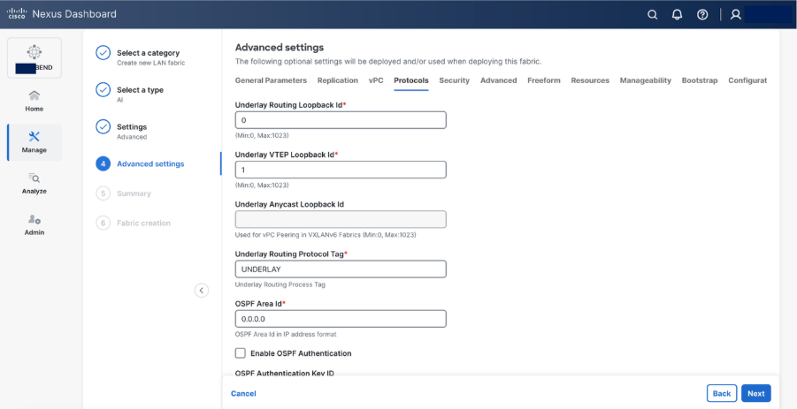
Step 5. Set basic parameters required for a VXLAN EVPN such as IP address, Authentication, BFD, and so on.
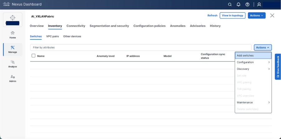
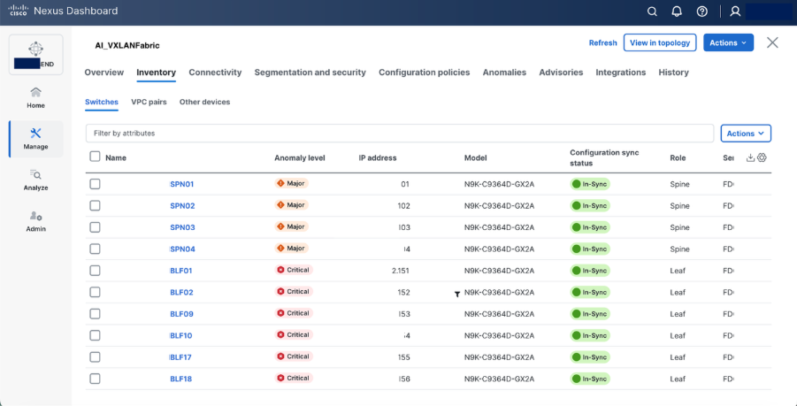
Step 6. Select Add switches to onboard the switches into Nexus Dashboard.
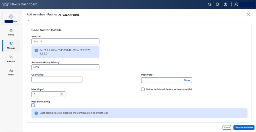
Step 7. Set roles as required “spine and leaf” and recalculate & deploy
Step 8. Set hardware QoS parameters using switch freeform configuration policy.
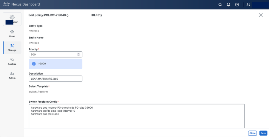
Switch freeform configuration:
hardware qos pfc static
Beginning with Release 10.5(2)F, the hardware qos pfc static command is supported on Cisco Nexus-9300-GX2A/GX2B Series switches. However, when this command is configured, breakout ports, SOD, and SPAN/ERSPAN (in Tx direction) are not supported.
The Cisco Nexus command hardware qos pfc static is needed on GX platform to achieve line-rate.
hardware profile dme load-interval
The hardware profile dme load-interval command on Cisco Nexus devices is used to configure the duration for collecting and averaging interface statistics, influencing how load and traffic metrics are calculated
NDI recommends that you must set the DME load interval to 10 when using the Real Time Visualization (RTEV) feature
hardware qos nodrop-PG-thresholds PG-size 39000
The hardware qos nodrop-pg-thresholds pg-size command is used to set the packet group size for the no-drop queue in hardware Quality of Service (QoS) policies. A "no-drop" queue is a special buffer used to prevent packet loss for high-priority traffic, and the pg-size value determines how many packets it can hold.
Note: This value is specific to Nexus 9364D-GX2A switch.
Step 9. Configure DLB on Spine using Switch Freeform configuration.
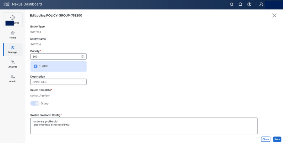
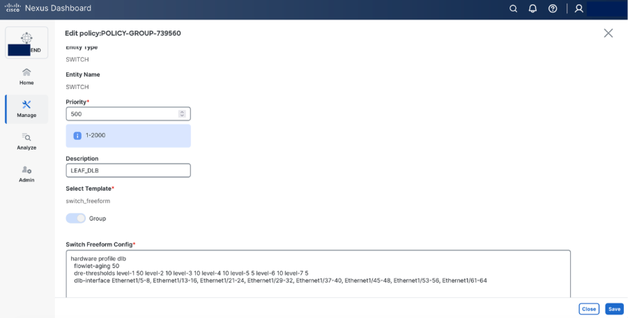
Step 10. Configure DLB on Leaf using switch freeform configuration.
Use Case: Multi-Tenant GPU-as-a-Service (GPUaaS)
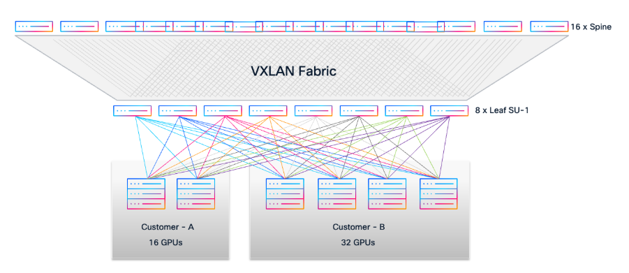
Consider a scenario where two customers require dedicated GPU resources from a shared AI/ML infrastructure with Cisco VXLAN EVPN Fabric:
Customer A requests access to 16 GPUs.
Customer B requests access to 32 GPUs.
● For Customer A, select 2 available UCS-C885A-M8-H26 servers (each with 8 GPUs, total 16 GPUs).
● For Customer B, select 4 available UCS-C885A-M8-H26 servers (each with 8 GPUs, total 32 GPUs).
● Using the cable matrix, identify the exact server-to-leaf switch ports for these servers to ensure optimal connectivity.
Network Segmentation and Provisioning
In Cisco Nexus Dashboard, create two distinct VLANs for tenant isolation:
● VLAN 10 for Customer A
● VLAN 20 for Customer B
● Provision two Networks in Nexus Dashboard:
● Attach Network VLAN 10 to the leaf ports connected to Customer A’s UCS servers.
● Attach Network VLAN 20 to the leaf ports connected to Customer B’s UCS servers.
This approach leverages the Layer 2 VXLAN EVPN fabric to provide secure, isolated Layer 2 domains for each customer, allowing them to consume GPU resources as a service (GPUaaS) without any cross-tenant traffic.
Advanced Telemetry and L3 Segmentation
For enhanced telemetry and traffic analytics, you can deploy Distributed Anycast Gateway (DAG) and introduce L3 segmentation.
Create two VRFs in Nexus Dashboard:
● VRF A for Customer A (assign VLAN 10 to VRF A with a unique SVI IP).
● VRF B for Customer B (assign VLAN 20 to VRF B with a unique SVI IP).
This enables per-customer routing domains and detailed flow visibility, supporting strict multi-tenancy and compliance requirements.
Monitoring Intelligent AI/ML Infrastructure
These are the capability overview of Cisco Nexus Dashboard.
● End-to-End Visibility: Provides comprehensive, real-time visibility into network topology, fabric health, and traffic flows across AI/ML clusters.
● AI/ML Workload Awareness: Correlates network performance metrics with specific AI/ML job traffic for precise troubleshooting and optimization.
● Real-Time Telemetry: Collects high-frequency, hardware-accelerated telemetry data (such as buffer utilization, latency, and microburst detection) from Nexus 9000 switches.
● Intelligent Traffic Analytics: Uses advanced analytics to identify congestion hotspots, dropped packets, and anomalies affecting GPU-to-GPU communication.
● Proactive Alerting: Automatically detects and notifies operators of faults, performance degradation, or configuration drift impacting AI/ML workloads.
● Historical Data and Trend Analysis: Stores and visualizes historical network data to uncover usage patterns, predict future needs, and support capacity planning.
● Integrated Troubleshooting Tools: Offers path tracing, hop-by-hop flow analysis, and root cause identification for rapid resolution of AI/ML connectivity issues.
● Actionable Insights: Delivers actionable recommendations to optimize performance, buffer allocation, and Quality of Service (QoS) for AI/ML environments.
This white paper presents a validated, scalable, and non-blocking data center blueprint optimized for AI/ML workloads, leveraging Cisco Nexus 9000 switches and VXLAN EVPN fabric. The rail-optimized, modular architecture enables efficient cabling, high throughput, and predictable low-latency connectivity across 96 NVIDIA GPU nodes in three scalable units. By using Cisco Unified Nexus Dashboard, organizations gain automated deployment, real-time observability, and advanced analytics for seamless operations. The design ensures multi-tenant segmentation, robust fault tolerance, and straightforward expansion as AI/ML requirements evolve. Overall, this approach empowers enterprises to harness the full potential of their GPU infrastructure with performance, flexibility, and operational simplicity.
VXLAN Network with MP-BGP EVPN Control Plane Design Guide
AI/ML Networking Best Practices
Cisco Nexus 9000 Series Quality of Service (QoS) Configuration
Cisco AI/ML Networking solutions
Cisco and the Cisco logo are trademarks or registered trademarks of Cisco and/or its affiliates in the U.S. and other countries. To view a list of Cisco trademarks, go to this URL: www.cisco.com/go/trademarks. Third-party trademarks mentioned are the property of their respective owners. The use of the word partner does not imply a partnership relationship between Cisco and any other company. (1721R)
Any Internet Protocol (IP) addresses and phone numbers used in this document are not intended to be actual addresses and phone numbers. Any examples, command display output, network topology diagrams, and other figures included in the document are shown for illustrative purposes only. Any use of actual IP addresses or phone numbers in illustrative content is unintentional and coincidental.
© 2026 Cisco Systems, Inc. All rights reserved.