VXLAN BGP EVPN
This chapter contains these sections:
VXLAN BGP EVPN
VXLAN BGP EVPN is a data center network overlay protocol suite that
-
enables scalable Layer 2 and Layer 3 connectivity between distributed network endpoints
-
uses BGP EVPN as the control plane to advertise MAC/IP address bindings, and
-
supports multi-tenant network virtualization with enhanced operational flexibility.
VXLAN encapsulates Layer 2 frames in Layer 3 UDP packets, enabling scalable network overlays. BGP EVPN provides a standards-based control plane that supports dynamic endpoint discovery and efficient traffic forwarding.
VXLAN BGP EVPN can be used to interconnect multiple data center sites, providing secure and isolated tenant networks across the infrastructure.
Auto-derived route distinguishers
An auto-derived route distinguisher (rd auto) is a VPN address-mapping mechanism that
-
uses a Type 1 encoding format combining a 4-byte BGP Router ID and a 2-byte numbering field
-
distinguishes between IP-VRF and MAC-VRF through different numbering schemes, and
-
enables unique identification across multiple VRFs.
In Cisco NX-OS, the auto-derived RD uses the IP address of the BGP Router ID (RID) for the 4-byte administrative field and the internal VRF identifier for the 2-byte numbering field (VRF ID). This format is specified in IETF RFC 4364 section 4.2.
The 2-byte numbering field is always derived from the VRF, but results in a different numbering scheme depending on its use for the IP-VRF or the MAC-VRF:
-
IP-VRF: The 2-byte numbering field for the IP-VRF uses the internal VRF ID, which starts at 1 and increases incrementally. VRF IDs 1 and 2 are reserved for the default VRF and the management VRF, respectively. The first custom-defined IP VRF uses VRF ID 3.
IP-VRF with BGP Router ID 192.0.2.1 and VRF ID 6: RD 192.0.2.1:6
-
MAC-VRF: The 2-byte numbering field for the MAC-VRF uses the VLAN ID + 32767, which results in 32768 for VLAN ID 1 and incrementing.
MAC-VRF with BGP Router ID 192.0.2.1 and VLAN 20: RD 192.0.2.1:32787
Route-target autos
A route-target (RT) auto is a route-target assignment method that
-
derives route-target values automatically based on system parameters
-
uses the Type 0 extended community encoding as described in IETF RFC 4364, and
-
constructs the route-target using the Autonomous System Number (ASN) and the Service Identifier (VNI).
The auto-derived route-target (using import/export/both auto) is based on the Type 0 encoding format as described in IETF RFC 4364 section 4.2. This encoding allows a 2-byte administrative field and a 4-byte numbering field.
Within Cisco NX-OS, the auto-derived route-target uses the ASN for the 2-byte administrative field. It uses the VNI for the 4-byte numbering field.
In multi-AS environments, route-targets must match the correct ASN portion. You may need to define or rewrite them to ensure compatibility. For more information, see rewrite-evpn-rt-asn.
Examples of an auto-derived Route-Target (RT)
-
For 2-byte ASN:
-
IP-VRF within ASN 65001 and L3VNI 50001 - Route-Target 65001:50001
-
MAC-VRF within ASN 65001 and L2VNI 30001 - Route-Target 65001:30001
-
-
For 4-byte ASN:
-
IP-VRF within ASN 65656 and L3VNI 50001 - Route-Target 23456:50001
-
MAC-VRF within ASN 65656 and L2VNI 30001 - Route-Target 23456:30001
When a 4-byte ASN is used, the 2-byte ASN field is set to 23456 (AS_TRANS) as specified in IETF RFC 6793 section 9; this value is registered by IANA as a special-purpose AS number to represent 4-byte ASNs in 2-byte fields.

Note
Beginning with Cisco NX-OS Release 9.2(1), auto-derived Route-Target for 4-byte ASN is supported.
-
Supported features and configuration limits for VXLAN BGP EVPN
VXLAN BGP EVPN has these supported features, platforms, and configuration limits for VXLAN BGP EVPN:
Configuration recommendations
-
Switch and port limitations:
-
The VXLAN network identifier (VNID) 16777215 is reserved and should explicitly not be configured.
-
Beginning with Cisco NX-OS Release 10.5(2)F, Ingress Replication and Multicast Underlay are supported on Cisco Nexus 9500 Series switches with N9K-X9736C-FX3 line card.
-
It is recommended to use the vpc orphan-ports suspend command for single attached and/or routed devices on a Cisco Nexus 9000 platform switch acting as vPC VTEP.
-
-
Feature limitations:
-
Mobility Sequence number of a locally originated type-2 route (MAC/MAC-IP) can be mismatched between vPC peers, with one VTEP having a sequence number K while other VTEP in the same complex can have the same route with sequence number 0. This does not cause any functional impact and the traffic is not impacted even after the host moves.
-
For SVI-related triggers (such as shut/unshut or PIM enable/disable), a 30-second delay was added, allowing the Multicast FIB (MFIB) Distribution module (MFDM) to clear the hardware table before toggling between L2 and L3 modes or vice versa.
-
You can configure EVPN over segment routing or MPLS. See the Cisco Nexus 9000 Series NX-OS Label Switching Configuration Guide, Release 9.3(x) for more information.
-
You can use MPLS tunnel encapsulation using the new CLI encapsulation mpls command. You can configure the label allocation mode for the EVPN address family. See the Cisco Nexus 9000 Series NX-OS Label Switching Configuration Guide, Release 9.3(x) for more information.
-
Routing protocol adjacencies using Anycast Gateway SVIs is not supported.
-
When running VXLAN EVPN, any SVI for a VLAN extended over VXLAN must be configured with Anycast Gateway. Any other mode of operation is not supported.
-
-
Command limitations:
-
In a VXLAN EVPN setup, border nodes must be configured with unique route distinguishers, preferably using the auto rd command. Not using unique route distinguishers across all border nodes is not supported. The use of unique route distinguishers is strongly recommended for all VTEPs of a fabric.
-
-
Cisco Nexus supports Type-6 EVPN routes (for IPv4) based on earlier version of draft-ietf-bess-evpn-igmp-mld-proxy draft, where SMET flag field is set as optional.
-
Non-Disruptive In Service Software Upgrade (ND-ISSU) is supported on Nexus 9300 with VXLAN enabled. For more information, see Cisco Nexus 9000 and 3000 Upgrade and ISSU Matrix .
Supported platform and releases for VXLAN BGP EVPN
|
Release |
Platforms |
|---|---|
|
9.3(3) |
Cisco Nexus 9300- FX/GX/FX2/FX3 platform switches. Cisco Nexus 9300-GX switch Cisco Nexus 9504 and 9508 with R-series line cards |
|
10.2(1q)F |
N9KC9332D-GX2B platform switches. |
|
10.2(3)F |
Cisco Nexus 9364D-GX2A, and 9348D-GX2A platform switches. |
|
10.4(1)F |
Cisco Nexus 9348GC-FX3, 9348GC-FX3PH, and 9332D-H2R switches. |
|
10.4(2)F |
Cisco Nexus 93400LD-H1 switches. |
|
10.4(3)F |
Cisco Nexus 9364C-H1 switches. |
|
10.5(2)F |
Cisco Nexus 9500 Series switches with N9K-X9736C-FX3 line card. |
|
10.5(3)F |
Cisco Nexus 9364E-SG2 Series switches |
|
Release |
Platform |
|---|---|
|
10.6(1)F |
Cisco Nexus 9336C-SE1 switches |
|
10.6(2)F |
Cisco Nexus 9396Y12C-SE1 and 9396T12C-SE1 switches. |
|
Release |
Platform |
|---|---|
|
10.6(2)F |
Cisco N9324C-SE1U and N9348Y2C6D-SE1U Smart switches. |
Unsupported features
-
Feature limitations:
-
DHCP snooping (Dynamic Host Configuration Protocol snooping) is not supported on VXLAN VLANs.
-
RACLs are not supported on VXLAN uplink interfaces. VACLs are not supported on VXLAN de-capsulated traffic in egress direction; this applies for the inner traffic coming from network (VXLAN) towards the access (Ethernet).
As a best practice, always use PACLs/VACLs for the access (Ethernet) to the network (VXLAN) direction. See the Cisco Nexus 9000 Series NX-OS Security Configuration Guide, Release 9.3(x) for other guidelines and limitations for the VXLAN ACL feature.
-
The Cisco Nexus 9000 QoS buffer-boost feature is not applicable for VXLAN traffic.
-
Scale
Note |
For information about VXLAN BGP EVPN scalability, see the Cisco Nexus 9000 Series NX-OS Verified Scalability Guide . |
-
In a VXLAN EVPN setup that has 2K VNI scale and 3900 new VNI scale configuration, the control plane down time may take more than 200 seconds. To avoid potential BGP flap, extend the graceful restart time to 300 seconds.
-
Beginning with Cisco NX-OS Release 10.2(2)F, the following scale limits are enhanced — Layer 2 VNIs, Extended Layer 2 VNIs, Layer 3 VNIs, SVI with Distributed Anycast Gateway, IPv4 and IPv6 host routes in internet-peering mode and the ECMP paths. For the VXLAN scale limit information, see the Cisco Nexus 9000 Series NX-OS Verified Scalability Guide, Release 10.2(2)F.
ARP suppression
-
The command clear ip arp interface vrf vrf-name force-delete on specific interface normally deletes entries from ARP belonging to that interface and will relearn on traffic. However, when ARP for same IP is resolved on all ECMP paths, force-deleting ARP entry belonging to one of the ECMP interface will result in automatic relearning of that entry unless that link is down.
-
IP unnumbered in EVPN underlay supports ECMP. Multiple IP unnumbered links are connected back to back between same switches. ARP will be resolved on all connected interfaces, thus providing ECMP.
-
ARP suppression is only supported for a VNI if the VTEP hosts the First-Hop Gateway (Distributed Anycast Gateway) for this VNI. The VTEP and the SVI for this VLAN have to be properly configured for the distributed Anycast Gateway operation, for example, global Anycast Gateway MAC address configured and Anycast Gateway feature with the virtual IP address on the SVI.
-
The ARP suppression setting must match across the entire fabric. For a specific VNID, all VTEPs must be either configured or not configured.
-
Beginning with Cisco NX-OS Release 10.5(2)F, ARP suppression is supported on Cisco Nexus 9500 Series switches with N9K-X9736C-FX3 line card.
-
Beginning with Cisco NX-OS Release 10.6(1)F, ARP suppression is supported on Cisco Nexus 9336C-SE1 switches.
-
Beginning with Cisco NX-OS Release 10.6(2)F, ARP suppression is supported on Cisco Nexus 9396Y12C-SE1 and 9396T12C-SE1 switches.
-
Beginning with Cisco NX-OS Release 10.6(2)F, ARP suppression is supported on Cisco N9324C-SE1U and N9348Y2C6D-SE1U Smart switches.
VXLAN BGP EVPN fabrics with eBGP
-
For VXLAN BGP EVPN fabrics with eBGP, the following recommendations are applicable:
-
It is recommended to use loopbacks for the eBGP EVPN peering sessions (overlay control-plane).
-
It is a best practice to use the physical interfaces for eBGP IPv4/IPv6 peering sessions (underlay).
-
-
Only eBGP peering between a VTEP and external nodes (Edge Router, Core Router or VNF) is supported.
-
eBGP peering from the VTEP to the external node using a physical interface or subinterfaces is recommended and it is a best practice (external connectivity).
-
The eBGP peering from the VTEP to the external node can be in the default VRF or in a tenant VRF (external connectivity).
-
The eBGP peering from the VTEP to a external node over VXLAN must be in a tenant VRF and must use the update-source of a loopback interface (peering over VXLAN).
-
Using an SVI for eBGP peering from the VTEP to the External Node requires the VLAN to be local (not VXLAN extended).
-
NVE interface
-
Bind the NVE source-interface to a dedicated loopback interface and do not share this loopback with any function or peerings of Layer-3 protocols. A best practice is to use a dedicated loopback address for the VXLAN VTEP function.
-
You must bind NVE to a loopback address that is separate from other loopback addresses that are required by Layer 3 protocols. NVE and other Layer 3 protocols using the same loopback is not supported.
-
The NVE source-interface loopback is required to be present in the default VRF.
-
During the vPC Border Gateway boot up process the NVE source loopback interface undergoes the hold down timer twice instead of just once. This is a day-1 and expected behavior.
-
The value of the delay timer on NVE interface must be configured to a value that is less than the multi-site delay-restore timer.
-
When SVI is enabled on a VTEP (flood and learn, or EVPN) regardless of ARP suppression, make sure that ARP-ETHER TCAM is carved using the hardware access-list tcam region arp-ether 256 double-wide command. This requirement does not apply to Cisco Nexus 9300-FX/FX2 /FX3 and 9300-GX platform switches and Cisco Nexus 9500 platform switches with X97160YC-EX and 9700- FX /FX3 line cards.
Supported Templates
-
When configuring VXLAN BGP EVPN, only the "System Routing Mode: Default" is applicable for the following hardware platforms:
-
Cisco Nexus 9300 platform switches
-
Cisco Nexus 9300-FX/FX2 /FX3 platform switches
-
Cisco Nexus 9300-GX /GX2 /H2R /H1 platform switches
-
Cisco Nexus 9500 platform switches with X97160YC-EX and X9700- FX/GX/FX3 line cards
-
-
Changing the “System Routing Mode” requires a reload of the switch.
VXLAN uplinks
-
Starting from Cisco NX-OS Release 9.3(5), new VXLAN uplink capabilities are introduced:
-
A physical interface in default VRF is supported as VXLAN uplink.
-
A parent interface in default VRF, carrying subinterfaces with VRF and dot1q tags, is supported as VXLAN uplink.
-
A subinterface in any VRF and/or with dot1q tag remains not supported as VXLAN uplink.
-
An SVI in any VRF remains not supported as VXLAN uplink.
-
In vPC with physical peer-link, a SVI can be leveraged as backup underlay, default VRF only between the vPC members (infra-VLAN, system nve infra-vlans).
-
On a vPC pair, shutting down NVE or NVE loopback on one of the vPC nodes is not a supported configuration. This means that traffic failover on one-side NVE shut or one-side loopback shut is not supported.
-
FEX host interfaces remain not supported as VXLAN uplink and cannot have VTEPs connected (BUD node).
-
-
You need to configure the VXLAN uplink with ip unreachables in order to enable Path maximum transmission unit (MTU) discovery (PMTUD) in a VXLAN set up. PMTUD prevents fragmentation in the path between two endpoints by dynamically determining the lowest MTU along the path from the packet's source to its destination.
-
Cisco Nexus 9500 platform switches with 9700 -FX or -GX or -FX3 line cards support 1G, 10G, 25G, 40G, 100G and 400G for VXLAN uplinks.
-
Cisco Nexus 9300- FX/FX2/FX3 and -GX support 1G, 10G, 25G, 40G, 100G and 400G for VXLAN uplinks.
-
Beginning with Cisco NX-OS Release 10.2(3)F, Cisco Nexus 9300-GX2 platform switches support 10G, 25G, 40G, 100G and 400G for VXLAN uplinks.
-
Beginning with Cisco NX-OS Release 10.4(1)F, Cisco Nexus 9332D-H2R switches support 10G, 25G, 40G, 100G and 400G for VXLAN uplinks.
-
Beginning with Cisco NX-OS Release 10.4(2)F, Cisco Nexus 93400LD-H1 switches support 10G, 25G, 40G, 100G and 400G for VXLAN uplinks.
-
Beginning with Cisco NX-OS Release 10.4(3)F, Cisco Nexus 9364C-H1 switches support 10G, 25G, 40G, 100G and 400G for VXLAN uplinks.
|
Platform |
Release |
Limitations |
|---|---|---|
|
Cisco Nexus 9336C-SE1 switches |
10.6(1)F |
|
|
Cisco Nexus 9396Y12C-SE1 and 9396T12C-SE1 switches |
10.6(2)F |
|
|
Platform |
Release |
Limitations |
|---|---|---|
|
Cisco N9324C-SE1U and N9348Y2C6D-SE1U Smart switches |
10.6(2)F |
|
UDP port
-
The Cisco Nexus 9000 platform switches use standards conforming UDP port number 4789 for VXLAN encapsulation. This value is not configurable.
SPAN
The following guidelines and limitations apply to VXLAN/VTEP using BGP EVPN:
-
SPAN source or destination is supported on any port.
Gateway functionality
-
Gateway functionality for VXLAN to MPLS (LDP), VXLAN to MPLS-SR (Segment Routing) and VXLAN to SRv6 can be operated on the same Cisco Nexus 9000 Series platform.
-
VXLAN to MPLS (LDP) Gateway is supported on the Cisco Nexus 3600-R and the Cisco Nexus 9500 with R-Series line cards.
-
VXLAN to MPLS-SR Gateway is supported on the Cisco Nexus 9300-FX2/FX3/GX and Cisco Nexus 9500 with R-Series line cards.
-
Beginning with Cisco NX-OS Release 10.2(3)F, VXLAN to MPLS-SR Gateway is supported on the Cisco Nexus 9300-GX2 platform switches.
-
Beginning with Cisco NX-OS Release 10.4(1)F, VXLAN to MPLS-SR Gateway is supported on the Cisco Nexus 9332D-H2R switches.
-
Beginning with Cisco NX-OS Release 10.4(2)F, VXLAN to MPLS-SR Gateway is supported on the Cisco Nexus 93400LD-H1 switches.
-
Beginning with Cisco NX-OS Release 10.4(3)F, VXLAN to MPLS-SR Gateway is supported on the Cisco Nexus 9364C-H1 switches.
-
-
VXLAN to SRv6 is supported on the Cisco Nexus 9300-GX platform.
-
Beginning with Cisco NX-OS Release 10.2(3)F, VXLAN to SRv6 is supported on the Cisco Nexus 9300-GX2 platform switches.
-
Beginning with Cisco NX-OS Release 10.4(1)F, VXLAN to SRv6 is supported on the Cisco Nexus 9332D-H2R switches.
-
Beginning with Cisco NX-OS Release 10.4(2)F, VXLAN to SRv6 is supported on the Cisco Nexus 93400LD-H1 switches.
-
Beginning with Cisco NX-OS Release 10.4(3)F, VXLAN to SRv6 is supported on the Cisco Nexus 9364C-H1 switches.
VXLAN and GRE co-existence
-
Beginning with Cisco NX-OS Release 10.2(3)F, VXLAN and GRE co-existence is supported on Cisco Nexus 9300- FX/FX2/FX3/GX/GX2 switches, and N9K-C93108TC-FX3P, N9K-C93180YC-FX3, N9K-X9716D-GX switches. Only GRE RX path (decapsulation) is supported. GRE TX path (encapsulation) is not supported.
-
Beginning with Cisco NX-OS Release 10.4(1)F, VXLAN and GRE co-existence is supported on Cisco Nexus 9332D-H2R switches. Only GRE RX path (decapsulation) is supported. GRE TX path (encapsulation) is not supported.
-
Beginning with Cisco NX-OS Release 10.4(2)F, VXLAN and GRE co-existence is supported on Cisco Nexus 93400LD-H1 switches. Only GRE RX path (decapsulation) is supported. GRE TX path (encapsulation) is not supported.
-
Beginning with Cisco NX-OS Release 10.4(3)F, VXLAN and GRE co-existence is supported on Cisco Nexus 9364C-H1 switches. Only GRE RX path (decapsulation) is supported. GRE TX path (encapsulation) is not supported.
-
Beginning with Cisco NX-OS Release 10.5(2)F, VXLAN and GRE co-existence is supported on Cisco Nexus 9500 Series switches with N9K-X9736C-FX3 line card.
ECMP resilient hashing
-
Resilient hashing is supported on the following switch platform with a VXLAN VTEP configured:
-
Cisco Nexus 9300- FX/FX2/FX3/GX support ECMP resilient hashing.
-
Cisco Nexus 9300 with ALE uplink ports does not support resilient hashing.
Note
Resilient hashing is disabled by default.
-
-
Beginning with Cisco NX-OS Release 10.2(3)F, the ECMP resilient hashing is supported on the Cisco Nexus 9300-GX2 platform switches.
-
Beginning with Cisco NX-OS Release 10.4(1)F, the ECMP resilient hashing is supported on the Cisco Nexus 9300-H2R platform switches.
-
Beginning with Cisco NX-OS Release 10.4(2)F, the ECMP resilient hashing is supported on the Cisco Nexus 93400LD-H1 platform switches.
-
Beginning with Cisco NX-OS Release 10.4(3)F, the ECMP resilient hashing is supported on the Cisco Nexus 9364C-H1 switches.
Static MAC support on BGP EVPN
-
Beginning with Cisco NX-OS Release 10.3(2)F, Static MAC for BGP EVPN is supported on Cisco Nexus 9300- FX/FXP/FX2/FX3/GX/GX2 Series switches.
-
Beginning with Cisco NX-OS Release 10.4(1)F, Static MAC for BGP EVPN is supported on Cisco Nexus 9300-H2R series switches.
-
Beginning with Cisco NX-OS Release 10.4(2)F, Static MAC for BGP EVPN is supported on Cisco Nexus 93400LD-H1 series switches.
-
Beginning with Cisco NX-OS Release 10.4(3)F, Static MAC for BGP EVPN is supported on Cisco Nexus 9364C-H1 switches.
-
The mac address-table static mac-address vlan vlan-id {[drop | interface {type slot/port} | port-channel number]} command is supported on BGP EVPN.
Best practice for configuring new L3VNI mode
Beginning with Cisco NX-OS Release 10.2(3)F, the new L3VNI mode is supported on Cisco Nexus 9300-X Cloud Scale Switches.
Beginning with Cisco NX-OS Release 10.6(1)F, the new L3VNI mode is supported on Cisco Nexus 9336C-SE1 switches.
Beginning with Cisco NX-OS Release 10.6(2)F, the new L3VNI mode is supported on Cisco Nexus 9396Y12C-SE1 and 9396T12C-SE1 switches.
Beginning with Cisco NX-OS Release 10.6(2)F, the new L3VNI mode is supported on Cisco N9324C-SE1U and N9348Y2C6D-SE1U Smart switches.
Use these best practices and adhere to these limitations when configuring the new L3VNI mode on Cisco Nexus switches:
-
Configuration order and dependencies:
-
Configure VRF-VNI-L3 before you configure interface vni .
-
Configure interface vni only if PBR/NAT is required.
-
Recognize that VRF-VNI-L3 implicitly creates the L3VNI interface, which does not appear in show running by default.
-
Do not use shut or no shut on interface vni ; running shut/no shut on the VRF applies to the L3VNI.
-
-
Feature and command usage:
-
You can configure PBR/NAT on interface vni . Alternatively, use no interface vni , or default interface vni to remove PBR/NAT if present.
-
Always apply NAT on the new interface vni . Apply decap-side PBR policies on interface vni and encap-side policies on the SVI of the encap node, ensuring both use identical syntax.
-
-
Configuration modification and removal:
-
Running no feature nv overlay removes all VRF-VNI-L3 and associated PBR/NAT configuration under VRF, but existing VRF configuration is retained.
-
Running no interface vni removes PBR/NAT configurations before removing interface vni .
-
The config-replace , rollback, and ND ISSU features are supported for new L3VNI mode.
-
-
Concurrent mode usage:
-
Use both old and new L3VNI configuration modes concurrently on the same switch if required.
-
Ensure that the VNI configuration mode is consistent across both vPC fabric peer systems.
-
-
Supported features with new L3VNI mode:
-
Leaf/VTEP features using L3VNIs
-
VXLAN EVPN (IR, multicast, IGMP Snooping, vPC, Distributed Anycast Gateway)
-
MCT-less vPC
-
VXLAN Multisite (Border Leaf, Border Spine, Border Gateway, anycast BGW, vPC BGW)
-
VXLAN PBR, NAT, QoS, NGOAM and DSVNI
-
VXLAN access features (QinVNI, selective QinVNI, BUD-Node, etc.)
-
4K scale L2VNI for VXLAN Port VLAN-Mapping
-
Beginning with Cisco NX-OS Release 10.3(1)F, TRM is supported for the new L3VNI mode.
-
-
Migration guidance:
-
To migrate from old to new mode, remove VLAN, vlan-vnsegment, and SVI configuration, keep interface nve1 member-vni-associate , and add VRF-VNI-L3 .
-
To revert from new to old mode, remove VRF-VNI-L3 , add VLAN/vlan-vnsegment, retain interface nve1 member-vni-associate , create SVI, and configure member-vni under VRF.
-
-
Upgrade and downgrade guidance:
-
After a software upgrade, verify that existing L3VNI configurations are functional. Configure additional L3VNIs if required. If you need to undo changes, revert the configuration.
-
Remove all new L3VNI configurations before downgrading. You can downgrade the software only after completing the cleanup.
-
After a software upgrade, verify that old L3VNI configuration remains valid and operational.
-
Configure VXLAN BGP EVPN
Enable VXLAN
Use this task when you need to configure VXLAN and EVPN fabric functionality on your device.
Follow these steps to enable VXLAN:
Before you begin
-
Ensure you have administrative access to the device.
-
Confirm that your device and software release support VXLAN and EVPN features.
Procedure
|
Step 1 |
Enter global configuration mode: configure terminal |
|
Step 2 |
Enable VLAN-based VXLAN: feature vn-segment |
|
Step 3 |
Enable NV overlay functionality: feature nv overlay |
|
Step 4 |
Enable VN-Segment for VLANs: feature vn-segment-vlan-based |
|
Step 5 |
Enable Switch Virtual Interface (SVI) support: feature interface-vlan |
|
Step 6 |
Activate the EVPN control plane for VXLAN: nv overlay evpn |
Configure VLAN and VXLAN VNI
Use this task to set up VLANs with associated VXLAN VNI mappings, typically required for Layer 2 network segmentation and virtualization on devices participating in EVPN fabrics.
Follow these steps to configure a VLAN and VXLAN VNI:
Note |
Steps 4 to 7 are optional for configuring the VLAN for VXLAN VNI. These steps are required only if you need a custom route distinguisher or route-target, rather than using auto derivation. |
Before you begin
-
Ensure you have administrative access to the network device.
-
Identify the VLAN and VNI numbers to be used.
Procedure
|
Step 1 |
Enter global configuration mode: configure terminal |
|
Step 2 |
Specify the VLAN: vlan number |
|
Step 3 |
Map the VLAN to a VXLAN VNI: vn-segment number This configures Layer 2 VNI under VXLAN VLAN. |
|
Step 4 |
Enter EVPN configuration mode for the VLAN: evpn |
|
Step 5 |
Specify the VNI for the EVPN instance: vni number l2 |
|
Step 6 |
(Optional) Specify the MAC-VRF's route distinguisher: rd auto |
|
Step 7 |
(Optional) Configure the route target for import and export of MAC prefixes: route-target both {auto | rt} Use auto for iBGP. For eBGP or asymmetric VNIs, manually specify the RT. Supported formats for RT include ASN2:NN, ASN4:NN, or IPV4:NN. |
Configure the new L3VNI mode
Before Cisco NX-OS Release 10.2(3)F, NX-OS standalone systems with VXLAN infrastructure supported a maximum of 4,000 VNIs. This could be either up to 4,000 Layer 2 VNIs with no Layer 3 VNIs, or a mix of Layer 2 and Layer 3 VNIs totaling up to 4,000, with Layer 3 VNIs limited to approximately 900. The restriction was due to each Layer 3 VNI requiring a VLAN mapping, and VLANs are capped at 4,000.
Starting with Cisco NX-OS Release 10.2(3)F, an enhancement allows you to configure Layer 3 VNIs using the l3 keyword. This increases the supported number of Layer 3 VNIs from 900 to 2,000, while still supporting up to 4,000 Layer 2 VNIs.
Follow these steps to configure the new L3VNI mode on a switch for a VXLAN-based network:
Before you begin
Ensure you have access to the switch with configuration privileges.
-
Identify the required VRF name and VNI numbers.
-
Verify that VXLAN feature is enabled on the switch.
Procedure
|
Step 1 |
Enter global configuration mode. Example: |
||||||
|
Step 2 |
Create or enter the VRF context for VXLAN. Example: |
||||||
|
Step 3 |
Specify the Layer 3 VNI for the VRF. Example:The L3 keyword indicates the new L3VNI mode. |
||||||
|
Step 4 |
Associate the Layer 3 VNI to the VRF using the NVE interface. Example: |
||||||
|
Step 5 |
(Optional) Assign a route map for IPv4 or IPv6 policy-based routing to the L3VNI interface.
|
||||||
|
Step 6 |
(Optional) Assign a route map for NAT to L3VNI interface. Example: |
||||||
|
Step 7 |
Verify the corresponding new L3VNI state. Example: |
Configure VRF for VXLAN routing
Use this task when setting up a VRF for VXLAN routing on your device. Steps 3–6 are optional unless you require custom route distinguisher or route-target values.
Follow these steps to configure the VRF for VXLAN routing:
Note |
Step 4 to step 7 are optional for configuring the VRF for VXLAN Routing and are only necessary in case of a custom route distinguisher or route-target requirement (not using auto derivation). |
Procedure
|
Step 1 |
Enter configuration mode: configure terminal |
||
|
Step 2 |
Create or select the VRF context: vrf context vrf-name |
||
|
Step 3 |
Specify the VNI for the VRF: vni number |
||
|
Step 4 |
Specify the IP-VRF's route distinguisher: rd auto |
||
|
Step 5 |
Configure the IPv4 or IPv6 unicast address family: address-family {ipv4 | ipv6} unicast |
||
|
Step 6 |
Configure the route target for import and export of IPv4 or IPv6 prefixes: route-target both {auto | rt} The RT is used for a per-IP-VRF prefix import/export policy. If you enter an RT, these formats are supported: ASN2:NN, ASN4:NN, or IPV4:NN.
|
||
|
Step 7 |
Set RTs specifically for EVPN: route-target both {auto | rt} evpn The RT is used for a per-VRF prefix import/export policy. If you enter an RT, these formats are supported: ASN2:NN, ASN4:NN, or IPV4:NN.
|
Configure SVI for core-facing VXLAN routing
You can set up the SVI for Layer 3 VXLAN routing towards the core.
Follow these steps to configure SVI for core-facing VXLAN routing:
Procedure
|
Step 1 |
Configure VLAN: vlan number |
||
|
Step 2 |
Map VLAN to VXLAN VNI: vn-segment number |
||
|
Step 3 |
Configure VLAN interface: interface vlan-number |
||
|
Step 4 |
Set the MTU size: mtu number Specify the MTU size in bytes (68-9216). |
||
|
Step 5 |
Assign the interface to VRF: vrf member vrf-name |
||
|
Step 6 |
Disable sending IP redirect messages for IPv4 and IPv6: no {ip | ipv6} redirects |
||
|
Step 7 |
Enable IPv4-based forwarding: ip forward |
||
|
Step 8 |
Enable IPv6 forwarding: ipv6 address use-link-local-only
|
The SVI is now configured for core-facing VXLAN routing, enabling Layer 3 connectivity as required.
Configure SVI for host-facing VXLAN routing
You can configure a host-facing SVI for VXLAN routing.
Follow these steps to configure the SVI for hosts, acting as Distributed Default Gateway.
Before you begin
Ensure you have:
-
Administrator access on the switch.
-
VXLAN and VRF features are enabled.
-
The system is operating on a supported platform and version.
Procedure
|
Step 1 |
Configure the distributed gateway virtual MAC address: fabric forwarding anycast-gateway-mac address
|
||
|
Step 2 |
Specify the VLAN ID: vlan number |
||
|
Step 3 |
Specify the VN-segment identifier for the VLAN: vn-segment number |
||
|
Step 4 |
Specify the VLAN interface: interface vlan-number |
||
|
Step 5 |
Assign the interface to the required VRF: vrf member vrf-name |
||
|
Step 6 |
Specify the SVI IP address: ip address address |
||
|
Step 7 |
Associate the SVI with anycast gateway functionality under VLAN configuration mode: fabric forwarding mode anycast-gateway [proxy] Beginning with Cisco NX-OS Release 10.6(3)F, a new proxy option is available to enable enhanced local proxy ARP on EVPN enabled SVIs. |
The switch interface is configured as a distributed anycast gateway for hosts in the VXLAN overlay.
What to do next
Validate the SVI configuration and ensure host connectivity across the VXLAN network.
Configure the NVE interface and VNIs using multicast
You can enable VXLAN network virtualization and multicast group communication to support bridging and routing for tenant networks.
Follow these steps to configure the NVE interface and VNIs using multicast:
Before you begin
-
Enable the NVE feature set on the device.
-
Confirm that the required loopback interfaces (for example, loopback1) are configured.
-
Ensure multicast routing is enabled in the underlying network.
Procedure
|
Step 1 |
Configure the NVE interface: interface nve-interface |
||
|
Step 2 |
Bind the NVE source-interface to a dedicated loopback interface: source-interface loopback1 |
||
|
Step 3 |
Define BGP as the mechanism for host reachability advertisement: host-reachability protocol bgp |
||
|
Step 4 |
Configure the multicast group globally for all VNIs on each NVE interface: global mcast-group ip-address {L2 | L3} This configuration applies to all Layer 2 and Layer 3 VNIs.
|
||
|
Step 5 |
Add Layer 2 VNIs to the tunnel interface: member vni vni |
||
|
Step 6 |
Configure the mcast group on a per-VNI basis: mcast-group ip address Add a multicast group specific to the Layer 2 VNI to override the global configuration.
|
||
|
Step 7 |
Add a Layer-3 VNI for each tenant VRF to the overlay: member vni vni associate-vrf
|
||
|
Step 8 |
Configure the mcast group on a per-VNI basis: mcast-group address Add a multicast group specific to the Layer 3 VNI to override the global configuration. |
What to do next
Verify the operational status of the NVE interface and VNIs. Ensure that multicast routing is configured correctly in the network.Configure the delay timer on the NVE interface
Configure the delay timer on NX-OS border leaf and AnyCast border gateway devices. This ensures that fabric and VRF peer route advertisements have enough time to occur after a reload.
Measure the programming time for peers, VNIs, and routes. Use the show forwarding internal trace nve-peer-history command to obtain this information, then add a 100-second buffer to the measured value to determine the optimal timer setting.
Follow these steps to configure the delay timer on the NVE interface:
Before you begin
-
Ensure you have administrator access to the NX-OS device.
-
Review previous reload timing. Add a 100-second buffer to determine the required delay timer.
Procedure
|
Step 1 |
Enter global configuration mode: configure terminal |
|
Step 2 |
Configure the NVE interface: interface nve nve-interface |
|
Step 3 |
Specify the delay timer value for NVE interface: fabric-ready time seconds The default value is 135 seconds. |
|
Step 4 |
(Optional) Verify the configured timer value: show nve interface nve1 detail |
Configure VXLAN EVPN ingress replication
Configure ingress replication for VXLAN EVPN to enable efficient handling of BUM traffic. The device exchanges VTEP IP addresses using the BGP EVPN control plane.
Follow these steps to set up VXLAN EVPN with ingress replication:
Before you begin
Ensure you have:
-
Enabled VXLAN.
-
Configured VLAN and VXLAN VNI.
-
Configured BGP on the VTEP.
-
Configured RD and Route Targets for VXLAN Bridging.
Procedure
|
Step 1 |
Configure the NVE interface: interface nve-interface |
||
|
Step 2 |
Define BGP as the mechanism for host reachability advertisement: host-reachability protocol bgp |
||
|
Step 3 |
Enable the VTEP globally for all VNIs: global ingress-replication protocol bgp This configuration allows the device to exchange local and remote VTEP IP addresses. It creates the ingress replication list, enables sending and receiving BUM traffic for the VNI, and overrides the global configuration.
|
||
|
Step 4 |
Add one Layer-3 VNI per tenant VRF to the overlay: member vni vni associate-vrf
|
||
|
Step 5 |
Add Layer 2 VNIs to the tunnel interface: member vni vni |
||
|
Step 6 |
Enable the VTEP to exchange local and remote VTEP IP addresses for each VNI to create the ingress replication list: ingress-replication protocol bgp This enables sending and receiving BUM traffic for the VNI and overrides the global configuration.
|
What to do next
Verify VXLAN EVPN ingress replication functionality. Check connectivity among VTEPs if needed.Configure BGP on the VTEP
You can configure BGP peers and enable the EVPN address family for proper VXLAN routing and control plane signaling.
Follow these steps to configure BGP on the VTEP:
Before you begin
-
Ensure you have console access to the VTEP.
-
Ensure you know the local AS number, router ID, and neighbor addresses.
Procedure
|
Step 1 |
Enter BGP router configuration mode: router bgp number |
||
|
Step 2 |
Specify the router ID: router-id address |
||
|
Step 3 |
Define each BGP neighbor and its remote AS: neighbor address remote-as number Define the L2VPN EVPN address family under each neighbor. |
||
|
Step 4 |
Enter the Layer 2 VPN EVPN address family under BGP: address-family l2vpn evpn
|
||
|
Step 5 |
(Optional) (If using eBGP and leaf switches share an AS number) Allow duplicate AS numbers in the AS path: Allowas-in |
||
|
Step 6 |
Configure extended community sending to neighbors: send-community extended |
||
|
Step 7 |
If you use VRFs, specify the VRF context and address family for IPv4 and IPv6: Example: |
||
|
Step 8 |
Enable ECMP for EVPN-transported IP prefixes in address families as required: maximum-paths path {ibgp} |
||
|
Step 9 |
Save the configuration and validate BGP and EVPN status with appropriate show commands. |
Configure iBGP for EVPN on the spine
You can set up iBGP on a spine device to enable EVPN functionality across the data center fabric.
Follow these steps to configure iBGP for EVPN on the spine:
Before you begin
-
Ensure you have assigned IP addressing and AS numbers for your BGP topology.
-
Ensure that leaf and spine devices are reachable.
Procedure
|
Step 1 |
Enter BGP configuration mode and specify the spine's autonomous system number: router bgp autonomous system number |
||
|
Step 2 |
Define each leaf as a BGP neighbor and specify its remote AS: neighbor address remote-as number |
||
|
Step 3 |
Enter the Layer 2 VPN EVPN address-family configuration mode under the BGP neighbor: address-family l2vpn evpn |
||
|
Step 4 |
Configure the spine to send extended communities to all EVPN neighbors: send-community extended |
||
|
Step 5 |
Configure the spine to act as a route reflector for its neighbors: route-reflector-client |
||
|
Step 6 |
(If using eBGP) Configure the spine to retain all route-target information in advertisements: retain route-target all
|
||
|
Step 7 |
(If using eBGP and AS numbers differ) Configure the spine to disable the peer AS check: address-family l2vpn evpn |
||
|
Step 8 |
(Optional) Disable the peer AS number check during route advertisement: disable-peer-as-check Configure this parameter on the spine for eBGP when all leafs are using the same AS but the spines have a different AS than leafs.
|
||
|
Step 9 |
(If needed) Apply a route map to ensure the next-hop remains unchanged when advertising to neighbors: route-map permitall out
|
What to do next
Verify BGP neighbor status and EVPN route propagation using show bgp l2vpn evpn summary command.
Configure eBGP for EVPN on the spine
You can set up eBGP on the spine switch to support EVPN by configuring the next-hop attribute, retaining route targets, and specifying neighbor information.
Follow these steps to configure eBGP for EVPN on the spine:
Before you begin
-
Confirm that spine and leaf devices are reachable via IP and BGP.
-
Collect the autonomous system numbers, neighbor IP addresses, and route-target values.
Procedure
|
Step 1 |
Configure a route-map to keep the next-hop unchanged for EVPN routes: route-map NEXT-HOP-UNCH permit 10 |
||
|
Step 2 |
Set next-hop address: set ip next-hop unchanged
|
||
|
Step 3 |
Specify BGP: router bgp autonomous system number |
||
|
Step 4 |
Configure address family Layer 2 VPN EVPN under the BGP neighbor: address-family l2vpn evpn |
||
|
Step 5 |
Configure retain route-target all under address-family Layer 2 VPN EVPN: retain route-target all
|
||
|
Step 6 |
Define neighbor: neighbor address remote-as number |
||
|
Step 7 |
Configure address family Layer 2 VPN EVPN under the BGP neighbor: address-family l2vpn evpn |
||
|
Step 8 |
Disable the peer AS number check during route advertisement: disable-peer-as-check If all leaf devices use the same autonomous system and the spines use a different autonomous system, configure this parameter on the spine for eBGP. |
||
|
Step 9 |
Allow extended community attributes and apply the NEXT-HOP-UNCH route-map to the neighbor. Example: |
Configure ARP suppression
ARP suppression optimizes network efficiency by allowing the switch to respond to ARP requests from its local cache instead of broadcasting them across the VLAN. The cache is populated by learning remote host IP or MAC information through BGP EVPN MAC advertisements. If the cache lacks a requested entry, the ARP request is broadcast to detect silent hosts.
Follow these steps to configure ARP suppression:
Before you begin
-
Confirm your switch platform supports ARP suppression.
-
Ensure you have access to the device and required privileges.
Procedure
|
Step 1 |
Create the network virtualization endpoint (NVE) interface: interface nve 1 |
|
Step 2 |
Configure ARP suppression globally for all Layer 2 VNIs within the NVE interface: global suppress-arp |
|
Step 3 |
Specify VNI ID: member vni vni-id |
|
Step 4 |
Configure to suppress ARP under Layer 2 VNI and overrides the global set default: suppress-arp |
|
Step 5 |
Disable the global ARP suppression setting on a specific VNI: suppress-arp disable |
Disable VXLANs
You can completely disable VXLAN features and related EVPN control plane settings on your network device.
Follow these steps to disable VXLANs:
Before you begin
Ensure you have administrator access to the device.
Procedure
|
Step 1 |
Enter configuration mode: configure terminal |
|
Step 2 |
Disable the EVPN control plane: no nv overlay evpn |
|
Step 3 |
Disable the global mode for all VXLAN bridge domains: no feature vn-segment-vlan-based |
|
Step 4 |
Disable the VXLAN overlay feature: no feature nv overlay |
|
Step 5 |
(Optional) Save the changes persistently through reboots and restarts: copy running-config startup-config |
Duplicate host detection mechanisms for IP and MAC addresses
Cisco NX-OS supports duplicate host detection for both IP addresses and MAC addresses to prevent conflicts in complex networks. Detection mechanisms rely on monitoring the number of host moves within set time intervals and automatically act when configured thresholds are met.
Duplicate IP address detection
The system detects duplicate IP addresses based on the number of detected "moves" within a specified time interval.
-
Default threshold: 5 moves within 180 seconds.
-
When a host appears simultaneously under two VTEPs,, the host mobility logic detects this event.
-
Refresh timeout for simultaneous host detection: 600 milliseconds (IPv4) and default 3 seconds (IPv6).
-
After exceeding the move threshold, the switch starts a 30-second hold-down (lock) timer to verify duplication persists (show fabric forwarding ip local-host-db vrf abc ).
-
This hold-down lock can occur 5 times in 24 hours; thereafter, the entry is permanently frozen.
-
When an IP address is permanently frozen, a syslog message is generated by HMM. 2021 Aug 26 01:08:26 leaf hmm: (vrf-name) [IPv4] Freezing potential duplicate host 192.0.2.30/32, reached recover count (5) threshold
|
Command |
Description |
|---|---|
|
Available sub-commands:
|
|
The number of host moves allowed in n seconds. The range is 1 to 1000 moves; default is 5 moves. |
|
The duplicate detection timeout in seconds for the number of host moves. The range is 2 to 36000 seconds; default is 180 seconds. |
|
Detects duplicate host addresses (limited to 100 moves) in a period of 10 seconds. |
Duplicate MAC address detection
MAC address duplication is detected using a similar move-count and time-interval mechanism:
-
After 5 moves in 180 seconds, a 30-second lock is applied.
-
This can occur up to 3 times in 24 hours before the switch permanently freezes the MAC entry.
-
A MAC entry stays frozen as long as matching local and remote entries exist (show l2rib internal permanently-frozen-list ).
-
Unconfiguring these detection commands resets them to default but does not disable freeze functionality.
-
l2rib dup-host-mac-detection
-
l2rib dup-host-recovery
-
-
Permanently frozen MAC addresses trigger a syslog message from L2RIB. 2017 Jul 5 10:27:34 leaf %$ VDC-1 %$ %USER-2-SYSTEM_MSG: Unfreeze limit (3) hit, MAC 0000.0033.3333in topo: 200 is permanently frozen - l2rib 2017 Jul 5 10:27:34 leaf %$ VDC-1 %$ %USER-2-SYSTEM_MSG: Detected duplicate host 0000.0033.3333, topology 200, during Local update, with host located at remote VTEP 192.0.2.4, VNI 2 - l2rib 2017 Jul 5 10:27:34 leaf %$ VDC-1 %$ %USER-2-SYSTEM_MSG: Unfreeze limit (3) hit, MAC 0000.0033.3334in topo: 200 is permanently frozen - l2rib 2017 Jul 5 10:27:34 leaf %$ VDC-1 %$ %USER-2-SYSTEM_MSG: Detected duplicate host 0000.0033.3334, topology 200, during Local update, with host l
|
Command |
Description |
|---|---|
|
Available sub-commands for L2RIB:
|
|
The duplicate detection timeout in seconds for the number of host moves. The range is 2 to 36000 seconds; default is 180 seconds. |
|
Detects duplicate host addresses (limited to 100 moves) in a period of 10 seconds. |
Configure event history size for L2RIB
Adjusting the event history size enables enhanced troubleshooting and logging for L2RIB features on the switch.
Follow these steps to set the event history size for L2RIB.
Procedure
|
Step 1 |
Enter global configuration mode. Example: |
||
|
Step 2 |
Set the event history size for the L2RIB component. Example: |
||
|
Step 3 |
Generate the event logs for required L2RIB objects. Example:L2RIB objects:
|
||
|
Step 4 |
Clear the set event history size for the L2RIB component. Example: |
Verifying the VXLAN BGP EVPN Configuration
To display the VXLAN BGP EVPN configuration information, enter one of the following commands:
|
Command |
Purpose |
||
|---|---|---|---|
|
show nve vrf |
Displays VRFs and associated VNIs |
||
|
show bgp l2vpn evpn |
Displays routing table information. |
||
|
show ip arp suppression-cache [detail | summary | vlan vlan | statistics ] |
Displays ARP suppression information. |
||
|
show vxlan interface |
Displays VXLAN interface status. |
||
|
show vxlan interface | count |
Displays VXLAN VLAN logical port VP count.
|
||
|
show l2route evpn mac [all | evi evi [bgp | local | static | vxlan | arp]] |
Displays Layer 2 route information. |
||
|
show l2route evpn fl all |
Displays all fl routes. |
||
|
show l2route evpn imet all |
Displays all imet routes. |
||
|
show l2route evpn mac-ip all show l2route evpn mac-ip all detail |
Displays all MAC IP routes. |
||
|
show l2route topology |
Displays Layer 2 route topology. |
||
|
show l2route evpn ethernet-segment all detail |
Displays detailed information about all Ethernet Segment Identifiers (ESIs) in an EVPN (Ethernet VPN) environment. |
Note |
Although the show ip bgp command is available for verifying a BGP configuration, as a best practice, it is preferable to use the show bgp command instead. |
VXLAN BGP EVPN iBGP topologies
A VXLAN BGP EVPN iBGP topology is a data center network design that
-
deploys VXLAN as an overlay technology to provide scalable Layer 2 connectivity over an IP-based Layer 3 fabric
-
establishes internal BGP (iBGP) sessions between leaf and spine switches to propagate endpoint reachability information, and
-
leverages Ethernet VPN (EVPN) as the control plane to enable efficient MAC and IP address advertisement, host mobility, and multipathing.
VXLAN BGP EVPN (iBGP) configuration example
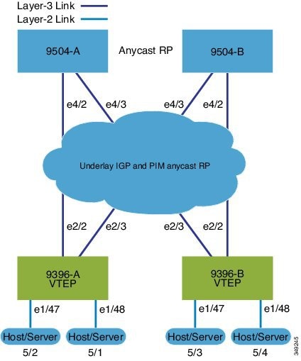
The following illustrates a sample VXLAN BGP EVPN iBGP topology and key configuration elements:

-
Spine Switches: Enable the EVPN control plane, OSPF, and PIM. Configure loopback interfaces for router IDs and Anycast-RP. Configure iBGP neighbors among all spine and leaf nodes.
-
Leaf Switches: Enable EVPN, OSPF, PIM, interface-VLAN, and VN-segment-VLAN features. Configure loopback interfaces for router ID and VTEP. Define VLAN-to-VNI mapping, enable distributed anycast gateways, and activate NVE (Network Virtualization Edge) interfaces.
-
Anycast-RP and ARP suppression: Use Anycast-RP, and configure TCAM regions for ARP suppression across the fabric.
-
BGP EVPN configuration: Configure iBGP neighbors (often using loopbacks as update sources) and EVPN address-families to signal MAC/IP information over the VXLAN overlays.
-
SVIs and VNIs: Define SVIs for VLANs mapped to VNIs, assigning server and core-facing interfaces.
Spine (9504-A)
-
Protocol and feature enablement
-
Enable the EVPN control plane
nv overlay evpn -
Enable the relevant protocols
feature ospf
feature bgp
feature pim
-
-
Loopback configuration
-
Configure Loopback for local Router ID, PIM, and BGP
interface loopback0 ip address 192.0.1.1/32 ip router ospf 1 area 0.0.0.0 ip pim sparse-mode -
Configure Loopback for Anycast RP
interface loopback1 ip address 192.0.2.1/32 ip router ospf 1 area 0.0.0.0 ip pim sparse-mode -
Configure Anycast RP
ip pim rp-address 192.0.2.1 group-list 224.0.0.0/4
ip pim anycast-rp 192.0.2.1 192.0.1.1
ip pim anycast-rp 192.0.2.1 198.51.100.20
-
-
Enable OSPF for underlay routing
router ospf 1 -
Configure interfaces for Spine-leaf interconnect
interface Ethernet4/2 ip address 192.168.1.42/24 ip router ospf 1 area 0.0.0.0 ip pim sparse-mode no shutdown interface Ethernet4/3 ip address 192.168.2.43/24 ip router ospf 1 area 0.0.0.0 ip pim sparse-mode no shutdown -
Configure BGP router bgp 65535 router-id 192.0.1.1 neighbor 198.51.100.30 remote-as 65535 update-source loopback0 address-family l2vpn evpn send-community both route-reflector-client neighbor 198.51.100.40 remote-as 65535 update-source loopback0 address-family l2vpn evpn send-community both route-reflector-client
Spine (9504-B)
-
Protocol and feature enablement
-
Enable the EVPN control plane
nv overlay evpn -
Enable the relevant protocols
feature ospf
feature bgp
feature pim
-
-
Loopback configuration
-
Configure Loopback for local Router ID, PIM, and BGP
interface loopback0 ip address 198.51.100.20/32 ip router ospf 1 area 0.0.0.0 ip pim sparse-mode -
Configure Loopback for Anycast RP
interface loopback1 ip address 192.0.2.1/32 ip router ospf 1 area 0.0.0.0 ip pim sparse-mode -
Configure Anycast RP
ip pim rp-address 192.0.2.1 group-list 224.0.0.0/4
ip pim anycast-rp 192.0.2.1 192.0.1.1
ip pim anycast-rp 192.0.2.1 198.51.100.20
-
-
Enable OSPF for underlay routing router ospf 1 -
Configure interfaces for Spine-leaf interconnect
interface Ethernet4/2 ip address 192.168.3.42/24 ip router ospf 1 area 0.0.0.0 ip pim sparse-mode no shutdown interface Ethernet4/3 ip address 192.168.4.43/24 ip router ospf 1 area 0.0.0.0 ip pim sparse-mode no shutdown -
Configure BGP
router bgp 65535
  router-id 198.51.100.20
  neighbor 198.51.100.30 remote-as 65535
    update-source loopback0
    address-family l2vpn evpn
      send-community both
      route-reflector client
  neighbor 198.51.100.40 remote-as 65535
    update-source loopback0
    address-family l2vpn evpn
      send-community both
      route-reflector client
Leaf (9396-A)
-
Protocol and feature enablement
-
Enable the EVPN control plane
nv overlay evpn -
Enable the relevant protocols
feature ospf
feature bgp
feature pim
feature interface-vlan
-
-
Enable VXLAN with distributed anycast-gateway using BGP EVPN feature vn-segment-vlan-based feature nv overlay fabric forwarding anycast-gateway-mac 0000.2222.3333 -
Enable OSPF for underlay routing
router ospf 1 -
Loopback configuration
-
Configure Loopback for local Router ID, PIM, and BGP
interface loopback0 ip address 198.51.100.30/32 ip router ospf 1 area 0.0.0.0 ip pim sparse-mode -
Configure Loopback for local VTEP IP
interface loopback1 ip address 198.51.100.33/32 ip router ospf 1 area 0.0.0.0 ip pim sparse-mode
-
-
Configure interfaces for Spine-leaf interconnect interface Ethernet2/2 no switchport ip address 192.168.1.22/24 ip router ospf 1 area 0.0.0.0 ip pim sparse-mode no shutdown interface Ethernet2/3 no switchport ip address 192.168.3.23/24 ip router ospf 1 area 0.0.0.0 ip pim sparse-mode shutdown -
Route Maps for Host SVIs and PIM RP configurations
-
Configure route-map to Redistribute Host-SVI (Silent Host)
route-map HOST-SVI permit 10 match tag 54321 -
Configure PIM RP
ip pim rp-address 192.0.2.1 group-list 224.0.0.0/4
-
-
VLAN, VRF, and VNI configuration
-
Create VLANs
vlan 1001-1002 -
Create overlay VRF VLAN and configure vn-segment
vlan 101 vn-segment 900001
-
-
SVI configuration
-
Configure Core-facing SVI for VXLAN routing
interface vlan101 no shutdown vrf member vxlan-900001 ip forward no ip redirects ipv6 address use-link-local-only no ipv6 redirects -
Create VLAN and provide mapping to VXLAN
vlan 1001 vn-segment 2001001 vlan 1002 vn-segment 2001002 -
Create VRF and configure VNI
vrf context vxlan-900001 vni 900001 rd autoNote
The rd auto and route-target commands are automatically configured unless one or more are entered as overrides.
address-family ipv4 unicast route-target both auto route-target both auto evpn address-family ipv6 unicast route-target both auto route-target both auto evpn -
Create a server facing SVI and enable distributed anycast-gateway.
interface vlan1001 no shutdown vrf member vxlan-900001 ip address 198.51.100.10/24 tag 54321 ipv6 address 2001:db8::1/64 tag 54321 fabric forwarding mode anycast-gateway interface vlan1002 no shutdown vrf member vxlan-900001 ip address 198.51.100.1/24 tag 54321 ipv6 address 2001:db8::2/64 tag 54321 fabric forwarding mode anycast-gateway
-
-
ARP suppression and NVE interface configurations
-
Configure ACL TCAM region for ARP suppression
Note
The hardware access-list tcam region arp-ether 256 double-wide command is not needed for Cisco Nexus 9300-FX/FX2 /FX3 and 9300-GX platform switches.
hardware access-list tcam region arp-ether 256 double-wide -
NVE interface - Basic mode and simplified mode options (if required)
Note
You can choose either of these two options for creating the NVE interface. Use Option 1 for a small number of VNIs. Use Option 2 to leverage the simplified configuration mode.
-
Option 1: interface nve1 no shutdown source-interface loopback1 host-reachability protocol bgp member vni 900001 associate-vrf member vni 2001001 mcast-group 239.0.0.1 member vni 2001002 mcast-group 239.0.0.1 -
Option 2: interface nve1 source-interface loopback1 host-reachability protocol bgp global mcast-group 239.0.0.1 L2 member vni 2001001 member vni 2001002 member vni 2001007-2001010
-
-
Configure interfaces for hosts/servers
interface Ethernet1/47 switchport switchport access vlan 1002 interface Ethernet1/48 switchport switchport access vlan 1001 -
Configure BGP
router bgp 65535 router-id 198.51.100.30 neighbor 10.1.1.1 remote-as 65535 update-source loopback0 address-family l2vpn evpn send-community both neighbor 198.51.100.20 remote-as 65535 update-source loopback0 address-family l2vpn evpn send-community both vrf vxlan-900001 address-family ipv4 unicast redistribute direct route-map HOST-SVI address-family ipv6 unicast redistribute direct route-map HOST-SVINote
The following commands in EVPN mode do not need to be entered.
evpn vni 2001001 l2 vni 2001002 l2Note
The rd auto and route-target auto commands are automatically configured unless one or more are entered as overrides.
rd auto route-target import auto route-target export autoNote
The rd auto and route-target commands are automatically configured unless you want to use them to override the import or export options.
Note
The following commands in EVPN mode do not need to be entered.
evpn vni 2001001 l2 rd auto route-target import auto route-target export auto vni 2001002 l2 rd auto route-target import auto route-target export auto
-
Leaf (9396-B)
-
Protocol and feature enablement
-
Enable the EVPN control plane
nv overlay evpn -
Enable the relevant protocols
feature ospf feature bgp feature pim feature interface-vlan
-
-
Enable VXLAN with distributed anycast-gateway using BGP EVPN
feature vn-segment-vlan-based feature nv overlay fabric forwarding anycast-gateway-mac 0000.2222.3333 -
Enable OSPF for underlay routing
router ospf 1 -
Loopback configuration
-
Configure Loopback for local Router ID, PIM, and BGP
interface loopback0 ip address 198.51.100.40/32 ip router ospf 1 area 0.0.0.0 ip pim sparse-mode -
Configure Loopback for local VTEP IP
interface loopback1 ip address 192.0.1.1/32 ip router ospf 1 area 0.0.0.0 ip pim sparse-mode
-
-
Configure interfaces for Spine-leaf interconnect interface Ethernet2/2 no switchport ip address 192.168.3.22/24 ip router ospf 1 area 0.0.0.0 ip pim sparse-mode no shutdown interface Ethernet2/3 no switchport ip address 192.168.4.23/24 ip router ospf 1 area 0.0.0.0 ip pim sparse-mode shutdown -
Route Maps for Host SVIs and PIM RP configurations
-
Configure route-map to Redistribute Host-SVI (Silent Host)
route-map HOST-SVI permit 10 match tag 54321 -
Configure PIM RP
ip pim rp-address 192.0.2.1 group-list 224.0.0.0/4
-
-
VLAN, VRF, and VNI configuration
-
Create VLANs
vlan 1001-1002 -
Create overlay VRF VLAN and configure vn-segment
vlan 101
  vn-segment 900001
-
-
SVI configuration
-
Configure Core-facing SVI for VXLAN routing
interface vlan101 no shutdown vrf member vxlan-900001 ip forward no ip redirects ipv6 address use-link-local-only no ipv6 redirects -
Create VLAN and provide mapping to VXLAN
vlan 1001 vn-segment 2001001 vlan 1002 vn-segment 2001002 -
Create VRF and configure VNI
vrf context vxlan-900001
  vni 900001
  rd auto
Note
The rd auto and route-target commands are automatically configured unless one or more are entered as overrides.
address-family ipv4 unicast route-target both auto route-target both auto evpn address-family ipv6 unicast route-target both auto route-target both auto evpn -
Create server facing SVI and enable distributed anycast-gateway
interface vlan1001 no shutdown vrf member vxlan-900001 ip address 198.51.100.10/24 ipv6 address 2001:db8::1/64 fabric forwarding mode anycast-gateway interface vlan1002 no shutdown vrf member vxlan-900001 ip address 198.51.100.1/24 ipv6 address 2001:db8::2/64 fabric forwarding mode anycast-gateway
-
-
ARP suppression and interface configuration
-
Configure ACL TCAM region for ARP suppression
Note
The hardware access-list tcam region arp-ether 256 double-wide command is not needed for Cisco Nexus 9300-FX/FX2 /FX3 and 9300-GX platform switches.
hardware access-list tcam region arp-ether 256 double-wideNote
You can choose either of these two command procedures for creating the NVE interfaces. Use Option 1 for a small number of VNIs. Use Option 2 to leverage the simplified configuration mode.
-
NVE interface - Basic mode and simplified mode options (if required)
Note
You can choose either of these two options for creating the NVE interface. Use Option 1 for a small number of VNIs. Use Option 2 to leverage the simplified configuration mode.
-
Option 1: interface nve1 no shutdown source-interface loopback1 host-reachability protocol bgp member vni 900001 associate-vrf member vni 2001001 mcast-group 239.0.0.1 member vni 2001002 mcast-group 239.0.0.1 -
Option 2: interface nve1 source-interface loopback1 host-reachability protocol bgp global mcast-group 239.0.0.1 L2 member vni 2001001 member vni 2001002 member vni 2001007-2001010
-
-
Configure interface vlan on Border Gateway (BGW)
interface vlan101 no shutdown vrf member evpn-tenant-3103101 no ip redirects ip address 198.51.100.50/16 ipv6 address 2001:db8::1/48 no ipv6 redirects fabric forwarding mode anycast-gateway -
Configure interfaces for hosts/servers
interface Ethernet1/47 switchport switchport access vlan 1002 interface Ethernet1/48 switchport switchport access vlan 1001 -
Configure BGP
router bgp 65535
  router-id 198.51.100.40
  neighbor 10.1.1.1 remote-as 65535
    update-source loopback0
    address-family l2vpn evpn
      send-community both
  neighbor 198.51.100.20 remote-as 65535
    update-source loopback0
    address-family l2vpn evpn
      send-community both
  vrf vxlan-900001
  vrf vxlan-900001
    address-family ipv4 unicast
      redistribute direct route-map HOST-SVI
    address-family ipv6 unicast
      redistribute direct route-map HOST-SVI
Note
-
These commands in EVPN mode do not need to be entered. evpn vni 2001001 l2 vni 2001002 l2 -
The rd auto and route-target auto commands are automatically configured unless one or more are entered as overrides. rd auto route-target import auto route-target export auto -
These commands in EVPN mode do not need to be entered. evpn vni 2001001 l2 rd auto route-target import auto route-target export auto vni 2001002 l2 rd auto route-target import auto route-target export auto
-
Note
When you have iBGP session between BGWs and EBGP fabric is used, you need to configure the route-map to make VIP or VIP_R route advertisement with higher AS-PATH when local VIP or VIP_R is down (due to reload or fabric link flap). A sample route-map configuration is provided below. In this example 192.0.2.1 is VIP address and 198.51.100.1 is BGP VIP route's nexthop learned from same BGW site.
ip prefix-list vip_ip seq 5 permit 192.0.2.1/32
ip prefix-list vip_route_nh seq 5 permit 198.51.100.1/32
route-map vip_ip permit 5
  match ip address prefix-list vip_ip
  match ip next-hop prefix-list vip_route_nh
  set as-path prepend 5001 5001 5001
route-map vip_ip permit 10
-
VXLAN BGP EVPN eBGP topologies
A VXLAN BGP EVPN eBGP topology is a data center overlay network architecture that
-
provides scalable Layer 2 and Layer 3 segmentation across a spine-leaf fabric
-
leverages BGP EVPN as a control plane for distributing MAC and IP address reachability information, and
-
enables automated multi-tenancy, efficient host mobility, and distributed gateway functions.
VXLAN BGP EVPN (eBGP) configuration example
The following example demonstrates a typical VXLAN BGP EVPN deployment using eBGP as the routing protocol between spine and leaf nodes. This design supports scalable, flexible data center environments.
Spine (9504-A)
-
Protocol and feature enablement
-
Enable the EVPN control plane
nv overlay evpn -
Enable the relevant features
feature bgp
feature pim
-
-
Loopback and Anycast RP configuration
-
Configure the loopback for the local router ID, PIM, and BGP.
interface loopback0 ip address 198.51.100.1/32 tag 12345 ip pim sparse-mode -
Configure loopback for Anycast RP
interface loopback1 ip address 192.0.2.1/32 tag 12345 ip pim sparse-mode -
Configure the Anycast RP.
ip pim rp-address 192.0.2.1 group-list 224.0.0.0/4
ip pim anycast-rp 192.0.2.1 198.51.100.1
ip pim anycast-rp 192.0.2.1 198.51.100.2
-
-
Route maps
-
Configure route-map used by eBGP for Spine
route-map NEXT-HOP-UNCH permit 10 set ip next-hop unchanged -
Configure route-map to Redistribute Loopback
route-map LOOPBACK permit 10
  match tag 12345
-
-
Interface configuration - Spine-leaf interconnect
-
Configure the interfaces for the spine-leaf interconnect.
interface Ethernet4/2
  ip address 192.168.1.42/24
  ip pim sparse-mode
  no shutdown
interface Ethernet4/3
  ip address 192.168.2.43/24
  ip pim sparse-mode
  no shutdown
-
-
BGP overlay (EVPN)
-
Configure the BGP overlay for the EVPN address family.
router bgp 100
  router-id 198.51.100.1
  address-family l2vpn evpn
    nexthop route-map NEXT-HOP-UNCH
    retain route-target all
  neighbor 192.0.2.0 remote-as 200
    update-source loopback0
    ebgp-multihop 3
    address-family l2vpn evpn
      send-community both
      disable-peer-as-check
      route-map NEXT-HOP-UNCH out
  neighbor 198.51.100.2 remote-as 200
    update-source loopback0
    ebgp-multihop 3
    address-family l2vpn evpn
      send-community both
      disable-peer-as-check
      route-map NEXT-HOP-UNCH out
-
-
BGP underlay (IPv4 unicast)
-
Configure BGP underlay for the IPv4 unicast address family.
address-family ipv4 unicast
    redistribute direct route-map LOOPBACK
  neighbor 192.168.1.22 remote-as 200
    update-source ethernet4/2
    address-family ipv4 unicast
      allowas-in
      disable-peer-as-check
  neighbor 192.168.2.23 remote-as 200
    update-source ethernet4/3
    address-family ipv4 unicast
      allowas-in
      disable-peer-as-check
-
Spine (9504-B)
-
Protocol and feature enablement
-
Enable the EVPN control plane
nv overlay evpn -
Enable the relevant protocols
feature bgp
feature pim
-
-
Loopback and Anycast RP configuration
-
Configure the loopback for the local router ID, PIM, and BGP.
interface loopback0 ip address 192.0.2.20/32 tag 12345 ip pim sparse-mode -
Configure the loopback for Anycast RP.
interface loopback1 ip address 192.0.2.1/32 tag 12345 ip pim sparse-mode -
Configure the Anycast RP.
ip pim rp-address 192.0.2.1 group-list 224.0.0.0/4
ip pim anycast-rp 192.0.2.1 198.51.100.1
ip pim anycast-rp 192.0.2.1 192.0.2.20
-
-
Route maps
-
Configure route-map used by eBGP for Spine
route-map NEXT-HOP-UNCH permit 10 set ip next-hop unchanged -
Configure route-map to Redistribute Loopback
route-map LOOPBACK permit 10
  match tag 12345
-
-
Interface configuration - Spine-leaf interconnect
-
Configure interfaces for Spine-leaf interconnect
interface Ethernet4/2
  no switchport
  ip address 192.168.3.42/24
  ip router ospf 1 area 0.0.0.0
  ip pim sparse-mode
  no shutdown
interface Ethernet4/3
  no switchport
  ip address 192.168.4.43/24
  ip router ospf 1 area 0.0.0.0
  ip pim sparse-mode
  shutdown
-
-
BGP overlay (EVPN)
-
Configure BGP overlay for the EVPN address family
router bgp 100
  router-id 192.0.2.20
  address-family l2vpn evpn
    nexthop route-map NEXT-HOP-UNCH
    retain route-target all
  neighbor 192.0.2.0 remote-as 200
    update-source loopback0
    ebgp-multihop 3
    address-family l2vpn evpn
      send-community both
      disable-peer-as-check
      route-map NEXT-HOP-UNCH out
  neighbor 198.51.100.2 remote-as 200
    update-source loopback0
    ebgp-multihop 3
    address-family l2vpn evpn
      send-community both
      disable-peer-as-check
      route-map NEXT-HOP-UNCH out
-
-
BGP underlay (IPv4 unicast)
-
Configure the BGP underlay for the IPv4 unicast address family.
address-family ipv4 unicast
    redistribute direct route-map LOOPBACK
  neighbor 192.168.3.22 remote-as 200
    update-source ethernet4/2
    address-family ipv4 unicast
      allowas-in
      disable-peer-as-check
  neighbor 192.168.4.43 remote-as 200
    update-source ethernet4/3
    address-family ipv4 unicast
      allowas-in
      disable-peer-as-check
-
Leaf (9396-A)
-
Feature and protocol enablement
-
Enable the EVPN control plane and networking features:
nv overlay evpn
    feature bgp
    feature pim
    feature interface-vlan
    feature vn-segment-vlan-based
    feature nv overlay
    fabric forwarding anycast-gateway-mac 0000.2222.3333
-
-
Routing Protocol Initialization
-
Enable OSPF for underlay routing. router ospf 1
-
-
Loopback interfaces
-
Configure Loopback for local router ID, PIM, and BGP and loopback1 (VTEP)
interface loopback0
  ip address 192.0.2.0/32
  ip pim sparse-mode
interface loopback1
  ip address 198.51.100.0/32
  ip pim sparse-mode
-
-
Spine-Leaf and host interface configuration
-
Set up interfaces for fabric and access
interface Ethernet2/2
  no switchport
  ip address 192.168.1.22/24
  ip pim sparse-mode
  no shutdown
interface Ethernet2/3
  no switchport
  ip address 192.168.4.23/24
  ip pim sparse-mode
  shutdown
interface Ethernet1/47
  switchport
  switchport access vlan 1002
interface Ethernet1/48
  switchport
  switchport access vlan 1001
-
-
VLAN, VRF, and VNI configuration
-
Create VLANs and map them to VXLAN segments. vlan 1001-1002 vlan 101 vn-segment 900001 vlan 1001 vn-segment 2001001 vlan 1002 vn-segment 2001002 -
Create the VRF and address families. vrf context vxlan-900001 vni 900001 rd auto address-family ipv4 unicast route-target both auto route-target both auto evpn address-family ipv6 unicast route-target both auto route-target both auto evpnNote
The rd auto and route-target commands are automatically configured unless one or more are entered as overrides.
-
-
SVI configuration
-
Configure core-facing and server-facing SVIs interface vlan101 no shutdown vrf member vxlan-900001 ip forward no ip redirects ipv6 address use-link-local-only no ipv6 redirects interface vlan1001 no shutdown vrf member vxlan-900001 ip address 192.0.2.10/24 tag 54321 ipv6 address2001:DB8:1:1::1/64 tag 54321 fabric forwarding mode anycast-gateway interface vlan1002 no shutdown vrf member vxlan-900001 ip address 198.51.100.20/24 tag 54321 ipv6 address 2001:DB8:1:1::1/64 tag 54321 fabric forwarding mode anycast-gateway
-
-
PIM RP, ARP suppression, and NVE interface
-
Enable PIM RP and configure ARP suppression region ip pim rp-address 192.0.2.1 group-list 224.0.0.0/4 hardware access-list tcam region arp-ether 256 double-wideNote
The hardware access-list tcam region arp-ether 256 double-wide command is not needed for Cisco Nexus 9300-FX/FX2 /FX3 and 9300-GX platform switches.
-
NVE interface - Basic mode and simplified mode options (if required)
Note
You can choose either of the following two options for creating the NVE interface. Use Option 1 for a small number of VNIs. Use Option 2 to leverage the simplified configuration mode.
-
Option 1: interface nve1 no shutdown source-interface loopback1 host-reachability protocol bgp member vni 900001 associate-vrf member vni 2001001 mcast-group 239.0.0.1 member vni 2001002 mcast-group 239.0.0.1 -
Option 2: interface nve1 source-interface loopback1 host-reachability protocol bgp global mcast-group 239.0.0.1 L2 member vni 2001001 member vni 2001002 member vni 2001007-2001010
-
-
-
Route Maps for Host SVIs and BGP configuration for underlay and overlay
-
Configure host SVI redistribution (Silent Host). route-map HOST-SVI permit 10 match tag 54321 -
Underlay (IPv4 unicast) router bgp 200 router-id 192.0.2.0 address-family ipv4 unicast redistribute direct route-map LOOPBACK neighbor 192.168.1.42 remote-as 100 update-source ethernet2/2 address-family ipv4 unicast allowas-in disable-peer-as-check neighbor 192.168.4.43 remote-as 100 update-source ethernet2/3 address-family ipv4 unicast allowas-in disable-peer-as-check -
Overlay (EVPN address family) address-family l2vpn evpn nexthop route-map NEXT-HOP-UNCH retain route-target all neighbor 198.51.100.1 remote-as 100 update-source loopback0 ebgp-multihop 3 address-family l2vpn evpn send-community both disable-peer-as-check route-map NEXT-HOP-UNCH out neighbor 192.0.2.20 remote-as 100 update-source loopback0 ebgp-multihop 3 address-family l2vpn evpn send-community both disable-peer-as-check route-map NEXT-HOP-UNCH out vrf vxlan-900001Note
-
The following commands in EVPN mode do not need to be entered. evpn vni 2001001 l2 vni 2001002 l2 -
The rd auto and route-target auto commands are automatically configured unless one or more are entered as overrides. rd auto route-target import auto route-target export auto -
The following commands in EVPN mode do not need to be entered. evpn vni 2001001 l2 rd auto route-target import auto route-target export auto vni 2001002 l2 rd auto route-target import auto route-target export auto
-
-
Leaf (9396-B)
-
Enable the control plane and features. nv overlay evpn feature bgp feature pim feature interface-vlan feature vn-segment-vlan-based feature nv overlay fabric forwarding anycast-gateway-mac 0000.2222.3333 -
Enable OSPF for underlay routing.
router ospf 1 -
Configure interfaces.
-
Configure loopback interfaces. interface loopback0 ip address 192.0.4.1/32 ip pim sparse-mode interface loopback1 ip address 192.0.44.1/32 ip pim sparse-mode -
Configure spine-leaf and server/host interfaces interface Ethernet2/2 no switchport ip address 192.168.3.22/24 ip pim sparse-mode no shutdown interface Ethernet2/3 no switchport ip address 192.168.2.23/24 ip pim sparse-mode shutdown interface Ethernet1/47 switchport switchport access vlan 1002 interface Ethernet1/48 switchport switchport access vlan 1001
-
-
Configure VLANs and VXLAN segment mapping vlan 1001-1002 vlan 101 vn-segment 900001 vlan 1001 vn-segment 2001001 vlan 1002 vn-segment 2001002 -
Configure VRF and address families vrf context vxlan-900001 vni 900001 rd auto address-family ipv4 unicast route-target both auto route-target both auto evpn address-family ipv6 unicast route-target both auto route-target both auto evpn -
Configure SVIs for routing and host connectivity interface vlan101 no shutdown vrf member vxlan-900001 ip forward no ip redirects ipv6 address use-link-local-only no ipv6 redirects interface vlan1001 no shutdown vrf member vxlan-900001 ip address 192.0.2.10/24 tag 54321 ipv6 address2001:DB8:1:1::1/64 tag 54321 fabric forwarding mode anycast-gateway interface vlan1002 no shutdown vrf member vxlan-900001 ip address 198.51.100.20/24 tag 54321 ipv6 address 2001:DB8:1:1::1/64 tag 54321 fabric forwarding mode anycast-gateway -
Configure PIM RP, ARP suppression, and NVE interface
-
Configure PIM RP, ARP suppression ip pim rp-address 192.0.2.1 group-list 224.0.0.0/4 hardware access-list tcam region arp-ether 256 double-wideNote
The hardware access-list tcam region arp-ether 256 double-wide command is not needed for Cisco Nexus 9300-FX/FX2 /FX3 and 9300-GX platform switches.
-
Configure NVE interface - Basic mode and simplified mode options (if required)
Note
You can choose either of the following two options for creating the NVE interface. Use Option 1 for a small number of VNIs. Use Option 2 to leverage the simplified configuration mode.
-
Option 1: interface nve1 no shutdown source-interface loopback1 host-reachability protocol bgp member vni 900001 associate-vrf member vni 2001001 mcast-group 239.0.0.1 member vni 2001002 mcast-group 239.0.0.1 -
Option 2: interface nve1 source-interface loopback1 host-reachability protocol bgp global mcast-group 239.0.0.1 L2 member vni 2001001 member vni 2001002 member vni 2001007-2001010
-
-
-
Configure route-maps and BGP for underlay and overlay route-map HOST-SVI permit 10 match tag 54321 router bgp 200 router-id 192.0.4.1 address-family ipv4 unicast redistribute direct route-map LOOPBACK neighbor 192.168.3.42 remote-as 100 update-source ethernet2/2 address-family ipv4 unicast allowas-in disable-peer-as-check neighbor 192.168.2.43 remote-as 100 update-source ethernet2/3 address-family ipv4 unicast allowas-in disable-peer-as-check address-family l2vpn evpn nexthop route-map NEXT-HOP-UNCH retain route-target all neighbor 198.51.100.1 remote-as 100 update-source loopback0 ebgp-multihop 3 address-family l2vpn evpn send-community both disable-peer-as-check route-map NEXT-HOP-UNCH out neighbor 192.0.2.20 remote-as 100 update-source loopback0 ebgp-multihop 3 address-family l2vpn evpn send-community both disable-peer-as-check route-map NEXT-HOP-UNCH out vrf vxlan-900001Note
-
The following commands in EVPN mode do not need to be entered. evpn vni 2001001 l2 vni 2001002 l2 -
The rd auto and route-target auto commands are automatically configured unless one or more are entered as overrides. rd auto route-target import auto route-target export auto -
The following commands in EVPN mode do not need to be entered. evpn vni 2001001 l2 rd auto route-target import auto route-target export auto vni 2001002 l2 rd auto route-target import auto route-target export auto
-
Sample outputs for EVPN/VXLAN show commands
This topic provides example outputs for various show commands used in Nexus switches for EVPN/VXLAN troubleshooting and verification.
This list describes the available show commands and their sample outputs:
-
show nve peers
9396-B# show nve peers Interface Peer-IP State LearnType Uptime Router-Mac --------- --------------- ----- --------- -------- ----------------- nve1 203.0.113.1 Up CP 00:00:38 6412.2574.9f27 -
show nve vni
9396-B# show nve vni Codes: CP - Control Plane DP - Data Plane UC - Unconfigured Interface VNI Multicast-group State Mode Type [BD/VRF] Flags --------- -------- ----------------- ----- ---- ------------------ ----- nve1 900001 n/a Up CP L3 [vxlan-900001] nve1 2001001 225.4.0.1 Up CP L2 [1001] nve1 2001002 225.4.0.1 Up CP L2 [1002] -
show vxlan interface
Note
The show vxlan interface command is not supported for the Cisco Nexus 9300-FX/FX2/FX3, and 9300-GX platform switches.
9396-B# show vxlan interface
Interface       Vlan    VPL Ifindex     LTL             HW VP
=========       ====    ===========     ===             =====
Eth1/47         1002    0x4c07d22e      0x10000         5697
Eth1/48         1001    0x4c07d02f      0x10001         5698
ARP suppression
-
show ip arp suppression-cache detail
9396-B# show ip arp suppression-cache detail

Flags: + - Adjacencies synced via CFSoE
L - Local Adjacency
R - Remote Adjacency
L2 - Learnt over L2 interface

Ip Address      Age      Mac Address    Vlan Physical-ifindex    Flags

192.0.2.54        00:06:41 0054.0000.0000 1001 Ethernet1/48        L
192.0.2.51        00:20:33 0051.0000.0000 1001 (null)              R
198.51.100.53     00:06:41 0053.0000.0000 1002 Ethernet1/47        L
198.51.100.52     00:20:33 0052.0000.0000 1002 (null)              R
L2 EVPN
-
show bgp l2vpn evpn summary
leaf3# show bgp l2vpn evpn summary BGP summary information for VRF default, address family L2VPN EVPN BGP router identifier 40.0.0.4, local AS number 10 BGP table version is 60, L2VPN EVPN config peers 1, capable peers 1 21 network entries and 21 paths using 2088 bytes of memory BGP attribute entries [8/1152], BGP AS path entries [0/0] BGP community entries [0/0], BGP clusterlist entries [1/4] Neighbor V AS MsgRcvd MsgSent TblVer InQ OutQ Up/Down State/PfxRcd 209.165.200.1 4 10 8570 8565 60 0 0 5d22h 6 leaf3# -
show bgp l2vpn evpn
leaf3# show bgp l2vpn evpn BGP routing table information for VRF default, address family L2VPN EVPN BGP table version is 60, local router ID is 209.165.200.4 Status: s-suppressed, x-deleted, S-stale, d-dampened, h-history, *-valid, >-best Path type: i-internal, e-external, c-confed, l-local, a-aggregate, r-redist, I-injected Origin codes: i - IGP, e - EGP, ? - incomplete, | - multipath, & - backup Network Next Hop Metric LocPrf Weight Path Route Distinguisher: 209.165.200.2:32868 *>i[2]:[0]:[10001]:[48]:[0000.8816.b645]:[0]:[0.0.0.0]/216 209.165.200.2 100 0 i *>i[2]:[0]:[10001]:[48]:[0011.0000.0034]:[0]:[0.0.0.0]/216 209.165.200.2 100 0 i -
show l2route evpn ethernet-segment all detail
ESI                  Orig Rtr. IP Addr   Prod    Ifindex NFNBitmapDF Election
-------------------------   --------------------    ------- ----------  --------
0300.0000.0000.0d00.0309    10.11.51.1           VXLAN   nve     11024       Modulus

0300.0000.0000.0dff.0309    10.11.51.1           VXLAN   nve     11024       Modulus

0300.0000.0000.0d00.0309    10.11.51.4           BGP     N/A     512         Per Flow
0300.0000.0000.0dff.0309    10.11.51.4           BGP     N/A     512         Per Flow
L2 Route
-
show l2route evpn mac all
leaf3# show l2route evpn mac all Topology Mac Address Prod Next Hop (s) ----------- -------------- ------ --------------- 101 0000.8816.b645 BGP 209.165.200.2 101 0001.0000.0033 Local Ifindex 4362086 101 0001.0000.0035 Local Ifindex 4362086 101 0011.0000.0034 BGP 209.165.200.2 -
show l2route evpn mac-ip all
leaf3# show l2route evpn mac-ip all Topology ID Mac Address Prod Host IP Next Hop (s) ----------- -------------- ---- ------------------------------------------------------ 101 0011.0000.0034 BGP 10.1.3.2 209.165.200.2 102 0011.0000.0034 BGP 10.1.3.2 209.165.200.2 -
show l2route evpn startup-route all [detail]
Flags - (V4):IPv4 Bcast address (V6):IPv6 Bcast address (D):Del Pending (S):Stale (C):Clear Topology ID Source Group (SG) Flags NFN Bitmap ----------- ---------------------------------------------------------------------------------------------------- ----------- ---------- 100 (0.0.0.0, 255.255.255.255) V4 8 Delivery SG: (11.1.1.2, 21.1.1.2) DCI Delivery SG: (11.1.1.3, 21.1.1.3) 1162 (::, ff00::) V6 8 Delivery SG: (2001:DB8::11:11, FE80::/10) DCI Delivery SG: (2001:DB8::11:11, ::) -
show l2route evpn startup-route evi <vpn-id> [detail]
Flags - (V4):IPv4 Bcast address (V6):IPv6 Bcast address
(D):Del Pending (S):Stale (C):Clear
Topology ID Source Group (SG)                                                                                    Flags       NFN Bitmap
----------- ---------------------------------------------------------------------------------------------------- ----------- ----------
1162        (::, ff00::)                                                                                         V6          8
Delivery SG: (2001:DB8::11:11, FE80::/10)
DCI Delivery SG: (2001:DB8::11:11, ::)
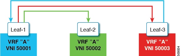
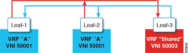
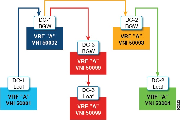
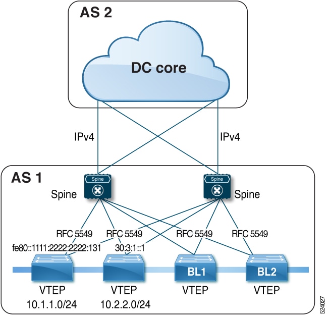
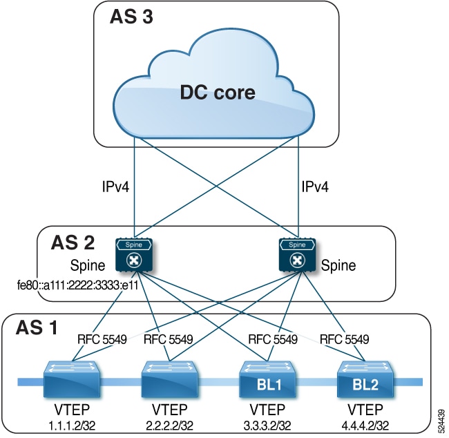
 Feedback