VXLAN Path Validation and Verification

VXLAN OAM or VXLAN NGOAM

VXLAN Operations, Administration, and Maintenance (OAM) or Next Generation Operations, Administration, and Maintenance (NGOAM) is a protocol that

  • enhance the management of VXLAN overlay networks during installation, monitoring, and troubleshooting, and

  • provide troubleshooting tools (VXLAN OAM tools) similar to ping, traceroute, or pathtrace for diagnosing problems in VXLAN networks.

These protocols use diagnostic channels to trace destinations and carry vital information.

VXLAN OAM, often referred to as NGOAM.

VXLAN OAM Tools

The VXLAN OAM tools are categorized as shown in the table. For more information on OAM tools, see Fault Isolation and Verification Tools.

Category Tools
Fault Verification Loopback Message
Fault Isolation Pathtrace Message

VXLAN OAM Payload

The OAM channel is used to identify the type of the VXLAN payload that is present in the OAM packets. The supported types of payloads are:

  • Conventional ICMP channel: These channels are used to facilitate communication with traditional hosts or switches that do not support the new OAM packet formats.

  • NVO3 draft Tissa channel: These channels are used to facilitate communication with supported hosts or switches, and they carry important diagnostic information. The term "channels" suggests a mechanism or pathway for delivering data.

    The VXLAN NVO3 draft Tissa OAM messages are identified using

    • Reserved OAM Ether-Type: This is a specific identifier used to recognize OAM packets. Ether-Type field indicates which protocol is encapsulated in the payload of an Ethernet frame.

    • Reserved Source MAC Address: Alternatively, OAM packets may be identified using a well-known reserved source MAC address. MAC addresses are unique identifiers assigned to network interfaces for communications on the physical network segment.

Guidelines and Limitations for VXLAN NGOAM

VXLANNGOAM has the following guidelines and limitations:

Beginning with Cisco NX-OS Release 10.2(3)F, you do not have to enable the VXLAN feature using the feature nv overlay command to use the NGOAM feature on intermediate nodes.

Supported Platform and Release for VXLAN NGOAM

Supported Release Supported Platform
9.3(3) and later Cisco Nexus 9300-FX/FX2/GX Series switches
9.3(5) and later Cisco Nexus 9300-FX3 Series switches
10.2(3)F and later Cisco Nexus 9300-GX2 Series switches
10.4(1)F and later Cisco Nexus 9332D-H2R switches
10.4(2)F and later Cisco Nexus 93400LD-H1 switches
10.4(3)F and later

Cisco Nexus 9364C-H1 switches

Cisco Nexus 9800 Series switches

10.5(2)F and later Cisco Nexus 9500 platform switches with N9K-X9736C-FX3 line card

10.5(3)F and later

Cisco Nexus 9364E-SG2-Q and 9364E-SG2-O switches

10.6(1)F and later

Cisco Nexus 9336C-SE1 switches

Configure VXLAN NGOAM

Follow these steps to configure the VXLAN NGOAM on Cisco Nexus switches.

Before you begin

Before you begin, ensure that the VXLAN configuration is complete.

Procedure


Step 1

Run the feature ngoam command in global configuration mode, to enable NGOAM feature.

Example:

switch# configure terminal
switch(config)# feature ngoam

Step 2

(Optional) Run the show running-config ngoam command to verify the ngoam configuration information.

Example:

switch# show run ngoam
feature ngoam

Configure NGOAM Profile

Follow these steps to configure the VXLAN profile on Cisco Nexus switches.

Before you begin

Before you begin, ensure that the feature ngoam configuration is complete.

Procedure


Step 1

Run the ngoam profile profile-id command in global configuration mode, to enable NGOAM profile.

Example:

switch# configure terminal
switch(config)# feature ngoam
switch(config)# ngoam profile 1
switch(config-ng-oam-profile)# 

Range: 1 to 1023. Default: NA.

Step 2

Use the [description | dot1q | flow | hop count | interface | oam-channel 2 | payload | sport] command to set the required options for configuring NGOAM profile.

Example:

Various options of NGOAM profiles configured under ngoam profile mode.
switch(config)# ngoam profile 1
switch(config-ngoam-profile)# oam-channel 2 
switch(config-ngoam-profile)#flow forward payload pad 0x2
switch(config-ngoam-profile)#sport 12345, 54321
Various options of NGOAM profiles configured under ngoam profile flow sub mode.
switch(config)# ngoam profile 1
switch(config-ngoam-profile)# flow forward 
switch(config-ng-oam-profile-flow)# oam-channel 2
switch(config-ng-oam-profile-flow)# payload 
  • description: Use this option to configure description of the profile.

  • dot1q: Use this option to specify encapsulation using the dot1q tag.

  • flow: Use this option to configure ngoam flow.

  • hop: Use this option to configure ngoam hop count. Range: 1 to 255.

  • interface: Use this option to configure NGOAM egress interface.

  • oam-channel: Use this option to set the Oam-channel toNVO3 tissa.

  • payload: Use this option to configure NGOAM payload.

  • sport: Use this option to configure NGOAM UDP source port range. Range: 1 to 65535.

Step 3

(Optional) Run the show running-config ngoam command to verify the ngoam profile configuration information.

Example:

switch# show run ngoam
feature ngoam
ngoam profile 1
oam-channel 2
flow forward payload pad 0x2

NGOAM configuration placement in show running-config command output has been updated. Previously, NGOAM configurations appeared before interface configurations. Beginning with Cisco NX-OS Release, 10.6(1)F NGOAM configurations appears after interface-level configurations in the show running-config command output.

Example before the Change:
ngoam profile 1
  oam-channel 2

interface Ethernet1/1
  no switchport
  ip address 60.60.60.1/24
  no shutdown
Example after the Change:
interface Ethernet1/1
  no switchport
  ip address 60.60.60.1/24
  no shutdown

interface loopback10
  vrf member Org1:vrf1
  ipv6 address 2010::10/128
ngoam profile 1
  oam-channel 2

Fault Isolation and Verification Tools

In a VXLAN network, you may want to find the list of switches that a frame traverses to reach its destination. If the loopback test from a source switch to a destination switch fails, you must find out the offending switch in the path.

The Fault Isolation and Verification Tools (VXLAN OAM tools) are used to

  • quickly identify problems in IP networks and

  • provide reachability information to hosts and VTEPs within a VXLAN network.

Category

Tools

Fault Verification

Loopback (Ping) Message

Fault Isolation

Traceroute and Pathtrace Message

Ping Message

The loopback (ping) message is a utility tool used for fault verification. This utility tool detects various errors and the path failures.

Note: A Ping, often referred to as a Loopback.

Topology of Ping Functionality

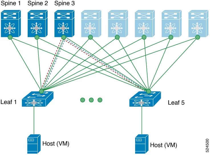
A Clos topology is shown where three core (spine) switches labeled Spine 1, Spine 2, and Spine 3 connect to five leaf switches.

The ping message validates these network reachability options using the ping command.

Here’s how validation of network reachability takes place from Leaf 1 (VTEP 1) to Leaf 5 (VTEP 2) on different OAM channels

ICMP Channel

NVO3 Draft Tissa Channel

Loopback message is initiated from Leaf 1 to Leaf 5

Loopback message is initiated from Leaf 1 to Leaf 5

Loopback message is forwarded as VXLAN encapsulated data packet based on the outer header from Spine 3

Loopback message is forwarded as VXLAN encapsulated data packet based on the outer header from Spine 3

Loopback is processed and responded in-band from Leaf 5.

  • Message is processed, payload is decapsulated and sent to host (VM)

  • Host generates the reply for the received payload and sends it to leaf 5.

  • Reply is processed for the response received from remote VTEP and sent in-band.

Loopback response is processed to Leaf 1

Loopback response is processed to Leaf 1.

text

Traceroute Message

The Traceroute message is a utility tool used for the fault Isolation. This utility tool traces various errors and the path failures.

Traceroute behavior differs between single-site and multisite scenarios, with varying outputs. It's important to understand the process of traceroute as mentioned in Traceroute Functionality in Single site and Traceroute Functionality in Multi-Site sections.

Traceroute Functionality in Single site

A Clos topology is shown where three core (spine) switches labeled Spine 1, Spine 2, and Spine 3 connect to five leaf switches.

The Traceroute message validates the path traversed by the packet in the VXLAN overlay using the Traceroute command.

Here’s how validation of network reachability takes place for Traceroute message from Leaf 1 (VTEP 1) to Leaf 5 (VTEP 2) on ICMP packets (channel-1), encapsulated in VXLAN.

  • A traceroute message is initiated from Leaf 1 to Leaf 5 through Spine 3.

  • Traceroute message is forwarded as a VXLAN encapsulated data packet based on the outer header from Spine 3.

  • Traceroute is processed and responded in-band on Leaf 5.

  • Traceroute is processed on Leaf 1.

Traceroute Functionality in Multi-Site

Traceroute-IP

As shown in the diagram, the multiple probes are sent with Time To Live (TTL) expiry or ACL hits, where:

  • Arrows pointing to a node indicate which hops the trace appears to hit.

  • Arrows pointing into a pipe represent the packet being encapsulated in VXLAN.

    When encapsulated, you won't see responses from nodes until it drops out of the pipe, as encapsulation adds a higher TTL to the outer packet, meaning that the TTL expiry upon which a traceroute depends doesn’t occur inside the pipe.

IP traceroute Process

The process described for the IP traceroute involves the following steps:

  • A regular UDP packet is initiated and encapsulated in VXLAN at the leaf switch.

  • The packet travels through the network and is decapsulated at the Border Gateway (BGW) of Site 1.

  • The BGW of Site 1 receives the packet and sends a response.

  • The packet is then re-encapsulated at BGW 1 and continues its journey through the network.

  • The packet exits the tunnel at BGW 2, where another response is received.

  • The packet is encapsulated when more and exits at a leaf in Site 2, prompting another response.

  • Finally, the packet reaches the leaf, and the final response is seen.

This sequence ensures that the packet is properly encapsulated and decapsulated as it traverses through different sites and network components, allowing for accurate tracing of the packet's path.

Traceroute - NVE

As shown in the diagram, in an NVE traceroute, NGOAM identifies that the traceroute is generated from a VTEP and involves the following steps:

  • Initially traces the underlay network up to the remote VTEP.

  • Switches to an overlay traceroute, functioning similarly to an IP traceroute.

  • Uses UDP requests for the underlay and ICMP requests for the overlay after the remote VTEP.

  • Probes are encapsulated in VXLAN upon reaching the remote VTEP.


    Note


    Probes in the local fabric are not encapsulated in VXLAN, allowing visibility of nodes.


  • After the local BGW, the output resembles a normal IP traceroute as probes enter pipes in multi-site fabrics.

Traceroute (NVE - IPv4 over IPv6)

The hybrid tracing results in a mix of IPv6 and IPv4 responses due to the transition between underlay and overlay networks

As shown in the diagram, in an NVE- IPv4 over IPv6 traceroute, NGOAM generates probes as IPv6 within the local underlay fabric and involves the following steps:

  • Receive IPv6 responses from the local spine and Border Gateway (BGW).

  • When the trace reaches the BGW, NGOAM switches to overlay tracing.

  • As the overlay is IPv4, receive IPv4 responses from the visible nodes beyond the BGW, as the packet effectively becomes IPv4.

Pathtrace Message

The Pathtrace message is a utility tool used for the fault Isolation. This utility tool traces various errors and path failures.

Pathtrace Functionality in Single site

A Clos topology is shown where three core (spine) switches labeled Spine 1, Spine 2, and Spine 3 connect to five leaf switches.

Pathtrace uses the NVO3 draft Tissa channel, encapsulated in the VXLAN encapsulation to reach the host and traces the path that is traversed by the packet in the VXLAN overlay using the Pathtrace command.

The NVO3 draft Tissa channel provides additional information about the path, such as ingress interface and egress interface. These packets stop at VTEP, and they do not reach the host. Therefore, only the VTEP responds.

Pathtrace Functionality in Multi-Site

As shown in the figure, pathtrace will generate a response from each node in the fabric. It uses a different channel (NVO3), which allows VXLAN-capable nodes in the fabric to process the packet specially due to ACL hits rather than TTL expiry. This makes it more capable of capturing the packet for processing, as long as the node supports NGOAM. Also, pathtrace receives special handling by NGOAM on the BGW, which adjusts the probe to allow it to continue into the next fabric.

Comparison of Traceroute and Pathtrace Message

Feature Traceroute Message Pathtrace Message
Channel Used ICMP channel NVO3 draft Tissa channel
Purpose Fault isolation by discovering the path packets take to reach their destination Provides additional diagnostic information such as interface load and hop statistics
Behavior on Unsupported Devices Continues to provide hop information Behaves as a simple traceroute and provides only hop information

Guidelines for Fault Isolation and Verification Tools

Beginning with NX-OS release 9.3(3), the Received field of the show ngoam pathtrace statistics summary command indicates all pathtrace requests received by the node on which the command is executed regardless of whether the request was destined to that node.

Examples for Fault Isolation and Verification Tools

Ping Message Examples

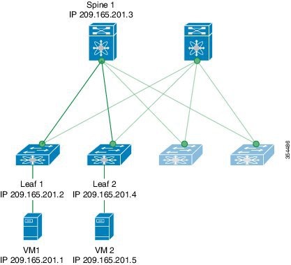
VXLAN OAM provides host visibility at the switch level, allowing a leaf to ping the host using the ping nve command.
Figure 1. VXLAN Network

The following examples display how to ping from Leaf 1 to VM2 via Spine 1 with channel 1 (unique loopback) and with channel 2 (NVO3 Draft Tissa).

  • switch# ping nve ip 209.165.201.5 vrf vni-31000 source 1.1.1.1 verbose
    
    Codes: '!' - success, 'Q' - request not sent, '.' - timeout, 'D' - Destination Unreachable, 'X' - unknown return code, 'm' - malformed request(parameter problem),
    'c' - Corrupted Data/Test, '#' - Duplicate response
    
    
    Sender handle: 34
    ! sport 40673 size 39,Reply from 209.165.201.5,time = 3 ms
    ! sport 40673 size 39,Reply from 209.165.201.5,time = 1 ms
    ! sport 40673 size 39,Reply from 209.165.201.5,time = 1 ms
    ! sport 40673 size 39,Reply from 209.165.201.5,time = 1 ms
    ! sport 40673 size 39,Reply from 209.165.201.5,time = 1 ms
    Success rate is 100 percent (5/5), round-trip min/avg/max = 1/4/18 ms Total time elapsed 49 ms
    

    Note


    Thesource ip-address 1.1.1.1 used in this example is a loopback interface configured on Leaf 1 in the same VRF as the destination IP address. For example, the VRF in this example is vni-31000.
  • switch# ping nve ip unknown vrf vni-31000 payload ip 209.165.201.5 209.165.201.4 payload-end verify-host
    <snip>
    Sender handle: 34
    !!!!!
    Success rate is 100 percent (5/5), round-trip min/avg/max = 1/4/18 ms Total time elapsed 49 ms
    
The following example displays the output of the MAC ping from Leaf 2 to Leaf 1 using NVO3 draft Tissa channel.
switch# ping nve mac 0050.569a.7418 2901 ethernet 1/51 profile 4 verbose

Codes: '!' - success, 'Q' - request not sent, '.' - timeout, 'D' - Destination Unreachable, 'X' - unknown return code, 'm' - malformed request(parameter problem),
'c' - Corrupted Data/Test, '#' - Duplicate response

Sender handle: 408
!!!!Success rate is 100 percent (5/5), round-trip min/avg/max = 4/4/5 ms Total time elapsed 104 ms

switch# show run ngoam
feature ngoam ngoam profile 4
oam-channel 2 ngoam install acl

Traceroute Message Examples

The following example displays how to traceroute from Leaf 1 to VM 2 through Spine 1.
switch# traceroute nve ip 209.165.201.5 vrf vni-31000 source 1.1.1.1 verbose


Codes: '!' - success, 'Q' - request not sent, '.' - timeout, 'D' - Destination Unreachable, 'X' - unknown return code, 'm' - malformed request(parameter problem),
'c' - Corrupted Data/Test, '#' - Duplicate response


Traceroute request to peer ip 209.165.201.4 source ip 209.165.201.2 Sender handle: 36
1 !Reply from 209.165.201.3,time = 1 ms
2 !Reply from 209.165.201.4,time = 2 ms
3 !Reply from 209.165.201.5,time = 1 ms
The following example displays the output of the pathtrace from Leaf 2 to Leaf 1.
switch# pathtrace nve ip 209.165.201.4 vni 31000 verbose
Path trace Request to peer ip 209.165.201.4 source ip 209.165.201.2 Sender handle: 42
Hop Code	ReplyIP	IngressI/f	EgressI/f	State
======================================================================
1	!Reply from 209.165.201.3, Eth5/5/1	Eth5/5/2	UP/UP
2	!Reply from 209.165.201.4, Eth1/3	Unknown	UP/DOWN

Pathtrace Message Examples

The following example displays how to pathtrace based on a payload from Leaf 2 to Leaf 1.
switch# pathtrace nve ip unknown vrf vni-31000 payload mac-addr 0050.569a.d927 0050.569a.a4fa ip 209.165.201.5 209.165.201.1 port 15334 12769 proto 17 payload-end
Codes: '!' - success, 'Q' - request not sent, '.' - timeout, 'D' - Destination Unreachable, 'X' - unknown return code, 'm' - malformed request(parameter problem),
'c' - Corrupted Data/Test, '#' - Duplicate response

Path trace Request to peer ip 209.165.201.4 source ip 209.165.201.2 Sender handle: 46
Hop Code Reply	IngressI/f EgressI/f State
======================================================================
1 !Reply from 209.165.201.3, Eth5/5/1 Eth5/5/2 UP/UP
2 !Reply from 209.165.201.4, Eth1/3	Unknown UP/DOWN

Note


When the total hop count to the final destination is more than 5, the path trace default TTL value is 5. Use the max-ttl option to complete the VXLAN OAM path trace completely.

For example: pathtracenve ip unknown vrf vrf-vni13001 payload ip 200.1.1.71 200.1.1.23 payload-end verbose max-ttl 10
The following example displays how to pathtrace NVE MAC
switch# pathtrace nve mac 0050.569a.d927 11 payload mac-addr 0050.569a.d927 0050.569a.a4fa payload-end vni 31000 verbose

Codes: '!' - success, 'Q' - request not sent, '.' - timeout, 'D' - Destination Unreachable, 'X' - unknown return code, 'm' - malformed request(parameter problem),
'c' - Corrupted Data/Test, '#' - Duplicate response, 'v' - Other - Use verbose to see the result

Path trace Request to peer ip 209.165.201.4 source ip 209.165.201.2 Sender handle: 46
Hop Code Reply	IngressI/f EgressI/f State
======================================================================
1 !Reply from 209.165.201.3, Eth5/5/1 Eth5/5/2 UP/UP
2 !Reply from 209.165.201.4, Eth1/3	Unknown UP/DOWN

Note


When the total hop count to the final destination is more than 5, the path trace default TTL value is 5. Use max-ttl option to finish VXLAN OAM path trace completely.

For example: pathtrace nve ip unknown vrf vrf-vni13001 payload ip 200.1.1.71200.1.1.23 payload-end verbose max-ttl 10


VXLAN EVPN Loop Detection and Mitigation

Causes and Impacts of Loop

Loops usually occur in a VXLAN EVPN fabric due to incorrect cabling on the south side (access side) of the fabric. When broadcast packets are injected into a network with a loop, the frame remains bridged in the loop. As more broadcast frames enter the loop, they accumulate and can cause a serious disruption of services.

VXLAN EVPN Loop Detection and Mitigation

Cisco NX-OS Release 9.3(5) introduces VXLAN EVPN loop detection and mitigation. This feature detects Layer 2 loops in a single VXLAN EVPN fabric or a Multi-Site environment. It operates at the port/VLAN level and disables the VLAN(s) on each port where a loop is detected. Administrators are also notified (via syslog) about the condition. In this way, the feature ensures that the network remains up and available.

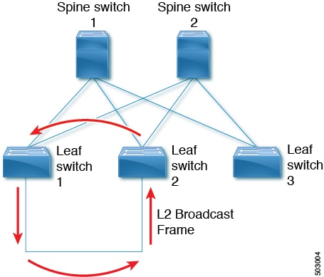
The following figure shows an EVPN fabric in which two leaf devices (Leaf1 and Leaf2) are directly connected on the south side due to incorrect cabling. In this topology, Leaf3 forwards an L2 broadcast frame to Leaf1. Then the broadcast frame is repeatedly forwarded between Leaf1 and Leaf2 through the south side and the fabric. The forwarding continues until the incorrect cabling is fixed.

Figure 2. Two Leaf Nodes Directly Connected

This feature operates in three phases:

  1. Loop Detection: Sends a loop detection probe under the following circumstances: when requested by a client, as part of a periodic probe task, and as soon as any port comes up.

  2. Loop Mitigation: Blocks the VLANs on a port once a loop has been discovered and displays a syslog message similar to the following:
    2020 Jan 14 09:58:44 Leaf1 %NGOAM-4-SLD_LOOP_DETECTED: Loop detected - Blocking vlan 1001 :: Eth1/3
    or
    2024 Sep  9 15:28:01 Node-11 %ETHPORT-3-IF_ERROR_VLANS_SUSPENDED: VLANs 2704 on Interface Ethernet1/49/1 are being suspended. (Reason: SUCCESS)

    Because loops can lead to incorrect local MAC address learning, this phase also flushes the local and remote MAC addresses. Doing so removes any MAC addresses that are incorrectly learned.

    In the previous figure, MAC addresses can be incorrectly learned because packets from hosts sitting behind the remote leaf (Leaf3) can reach both Leaf1 and Leaf2 from the access side. As a result, the hosts incorrectly appear local to Leaf1 and Leaf2, which causes the leafs to learn their MAC addresses.

  3. Loop Recovery: Once a loop is detected on a particular port or VLAN and the recovery interval has passed, recovery probes are sent to determine if the loop still exists. When NGOAM recovers from the loop, a syslog message similar to the following appears:

    2020 Jan 14 09:59:38 Leaf1 %NGOAM-4-SLD_LOOP_GONE: Loop cleared - Enabling vlan 1001 
    :: Eth1/3
    or
    2024 Sep  9 15:24:23 Node-11 %ETHPORT-3-IF_ERROR_VLANS_REMOVED: VLANs 384 on Interface Ethernet1/49/1 are removed from suspended state.

    Note


    The default logging level for NGOAM does not generate a syslog message. Modifying the logging level of NGOAM to 5 with "logging level ngoam 5" will result in a syslog message being generated when a loop is detected.


Various Loop Scenarios

Southbound Loop Detection on Layer-3 Interface

Beginning with NX-OS release 10.4(3)F, Cisco Nexus switches support Southbound Loop Detection (SLD) on a Layer-3 (L3) Ethernet and L3 port-channel interfaces in a single VXLAN EVPN fabric or a Multi-Site environment. Before this release, the SLD feature was supported only on Layer-2 interfaces.

This feature detects loops in southbound side (L2 access switches) that are connected to a single leaf switch through an L3 interface or port channel.

When the SLD feature is enabled on the L3 interface, it sends periodic SLD probes to detect loops in a downstream tenant's Layer-2 domain. It continues to monitor for loops and blocks the L3 interface on detection until the user takes action to correct the condition in the downstream L2 domain.

Functionalities of SLD on Layer-3 Interface

  • Isolates a single L3 attached tenant to prevent the impact of a storm from propagating beyond a single L3 boundary due to control-plane policing congestion.

  • Detects downstream L2 loops and blocks attached L3 interface or L3 port-channel if a loop is detected by receipt of an originated NGOAM probe.

  • Unblocks the L3 port if the originated NGOAM probes are no longer detected.

Topology Overview of SLD on Layer-3 Interface

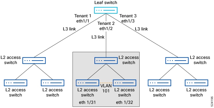
The following figure shows an EVPN fabric with a leaf switch configured with three VRFs (Tenant 1, Tenant 2, and Tenant 3). These VRFs are connected to L2 access switches on the south side using different L3 ports and their respective L3 interfaces.

This feature operates in three phases:

  • Loop Detection: The SLD L3 feature sends periodic probes to detect loops in the downstream tenant's Layer-2 domain (L2 access switches).

    SLD sends a loop detection probe under the following circumstances: when requested by a client, as part of a periodic probe task, and when any port comes up.

    For example: Tenant 2 accidentally creates a bridging loop due to a cabling error while disabling STP on local VLAN 101​. This triggers an ARP storm toward Eth1/2, consuming the entire CoPP Class Normal policer,​ which causes CoPP policer saturation​ in Tenant 1 and Tenant 3.

    2024 Jun 27 02:34:39 tenant2 %L2FM-2-L2FM_CONTINUOUS_MAC_MOVE: Mac Address (f80f.6f96.a127) in Vlan 101 is moving continuously. Mac moved between Eth1/32 to Eth1/31. Please enable 'logging level l2fm 4' for verbose output.

  • Loop Mitigation: Blocks the L3 port when a loop has been discovered and displays a syslog message like the following indicating the loop detection and port status changes.
    2024 Jun 27 02:37:50 leaf %ETHPORT-5-IF_DOWN_NONE: Interface Ethernet1/2 is down (None)
    2024 Jun 27 02:37:50 leaf %ETHPORT-5-IF_DOWN_ERROR_DISABLED: Interface Ethernet1/2 is down (Error disabled. Reason:error)
    2024 Jun 27 02:38:52 leaf %ETHPORT-5-IF_ERRDIS_RECOVERY: Interface Ethernet1/2 is being recovered from error disabled state (Last Reason:error)
    2024 Jun 27 02:38:54 leaf %ETHPORT-5-IF_DOWN_ERROR_DISABLED: Interface Ethernet1/2 is down (Error disabled. Reason:error)
    !
    leaf# show ngoam loop-detection status l3 
    Port       Status       NumLoops      DetectionTime             ClearedTime
    ========================================================================================
    
    Eth1/2     BLOCKED      2             Tue Jun 27 02:38:54 2024  Tue Jun 27 02:38:52 2024

    After each probe error recovery interval, the blocked L3 port is brought up to send probes and recheck for the loop. Now, the Eth1/2 L3 interface is moved from the Blocked state to the Forwarding state. The probe checks for the loop, and if the loop still exists, it moves the eth1/2 L3 interface back to the Blocked state. This process continues until the user corrects the bridging loop within the L2 domain.

    The following sample output displays the state (blocking and unblocking) based on the probe generated:
    2024 Jun 27 20:26:56 leaf %NGOAM-4-SLD_L3_LOOP_DETECTED: Loop detected - Blocking port Eth1/2
    2024 Jun 27 20:26:56 leaf %ETHPORT-5-IF_DOWN_NONE: Interface Ethernet1/2 is down (None)
    2024 Jun 27 20:26:56 leaf %ETHPORT-5-IF_DOWN_ERROR_DISABLED: Interface Ethernet1/2 is down (Error disabled. Reason:error)
    2024 Jun 27 20:27:58 leaf %ETHPORT-5-IF_ERRDIS_RECOVERY: Interface Ethernet1/2 is being recovered from error disabled state (Last Reason:error)
    2024 Jun 27 20:27:58 leaf %NGOAM-4-SLD_L3_LOOP_GONE: Loop cleared - Enabling port Eth1/2
    2024 Jun 27 20:28:00 leaf %NGOAM-4-SLD_L3_LOOP_DETECTED: Loop detected - Blocking port Eth1/2
    2024 Jun 27 20:28:01 leaf %ETHPORT-5-IF_DOWN_ERROR_DISABLED: Interface Ethernet1/2 is down (Error disabled. Reason:error)
    
  • Loop Recovery: When the cabling error is fixed, the loops on the southbound side will be removed. After the recovery interval has passed, recovery probes will be sent from the L3 interface on the leaf switch to determine whether a loop exists. If the loop is resolved, the port will remain in the forwarding state, and the following syslog message will be generated.
    2024 Jun 27 22:39:26 tenant2 %ETHPORT-5-IF_DOWN_ADMIN_DOWN: Interface Ethernet1/32 is down (Administratively down)
    2024 Jun 27 22:39:56 tenant2 %ETHPORT-5-SPEED: Interface Ethernet1/2, operational speed changed to 10 Gbps
    2024 Jun 27 22:39:56 tenant2 %ETHPORT-5-IF_DUPLEX: Interface Ethernet1/2, operational duplex mode changed to Full
    2024 Jun 27 22:39:56 tenant2 %ETHPORT-5-IF_RX_FLOW_CONTROL: Interface Ethernet1/2, operational Receive Flow Control state changed to off
    2024 Jun 27 22:39:56 tenant2 %ETHPORT-5-IF_TX_FLOW_CONTROL: Interface Ethernet1/2, operational Transmit Flow Control state changed to off
    2024 Jun 27 22:39:56 tenant2 %ETHPORT-5-IF_UP: Interface Ethernet1/17 is up
    2024 Jun 27 22:41:03 tenant2 %VSHD-5-VSHD_SYSLOG_CONFIG_I: Configured from vty by admin on 10.82.195.201@pts/2

Note


The default logging level for NGOAM does not generate a syslog message. Modifying the logging level of NGOAM to 5 with "logging level ngoam 5" will result in a syslog message being generated when a loop is detected.


L2 and L3 SLD Feature Functionality Comparison

Features SLD on L2 Interface SLD on L3 Interface
Operation level Port and VLAN level Ethernet and L3 port-channel
Environment Single-Site and Multi-Site Single-Site and Multi-Site
Loop detection Detects the loop of a particular port or VLAN Detects downstream L2 loops and blocks the L3 interfaces or L3 port channels
Loop mitigation Blocks the VLANs on a port once a loop has been discovered and displays a syslog message Isolates a single L3 attached tenant to prevent the impact of a storm from propagating beyond a single L3 boundary by consuming shared CoPP policer resources
Loop blocking Breaks the southbound loops Isolates detected loops from impacting the control plane by shedding storm-related traffic
Loop recovery Sends recovery probes, re-enables VLANs, and logs syslog messages once the loop is cleared Sends recovery probes, re-enables the port or ethernet interfaces if the NGOAM process no longer sees NGOAM probes, and logs syslog messages once the loop is cleared

Guidelines and Limitations for VXLAN EVPN Loop Detection and Mitigation

VXLAN EVPN loop detection and mitigation has the following guidelines and limitations:

  • VXLAN EVPN loop detection and mitigation is supported in both STP and STP-less environments.

  • To be able to detect loops across sites for VXLAN EVPN Multi-Site deployments, the ngoam loop-detection command needs to be configured on all border gateways in the site where the feature is being deployed.

  • VXLAN EVPN loop detection and mitigation isn't supported with the following features:

    • Private VLANs

    • VLAN translation

    • ESI-based multihoming

    • VXLAN Cross Connect

    • Q-in-VNI

    • EVPN segment routing (Layer 2)


    Note


    Ports or VLANs configured with these features must be excluded from VXLAN EVPN loop detection and mitigation. You can use the disable {vlan vlan-range} [port port-range] command to exclude them.


Supported Platform and Release for VXLAN EVPN Loop Detection and Mitigation

Supported Release Supported Platform
9.3(5) and later

Cisco Nexus 9300-FX/FX2 Series switches

Cisco Nexus 9500 platform switches with X97160YC-EX and 9700-FX line cards

10.1(1) and later Cisco Nexus 9300-FX3/GX Series switches
10.2(3)F and later Cisco Nexus 9300-GX2 Series switches
10.4(1)F and later Cisco Nexus 9332D-H2R Series switches
10.4(2)F and later Cisco Nexus 93400LD-H1 Series switches
10.4(3)F and later Cisco Nexus 9364C-H1 Series switches

10.5(2)F and later

Cisco Nexus 9500 platform switches with 9700-FX3 line cards

Guidelines and Limitations for SLD on L3 Interface

  • SLD is supported only on L3 ethernet and L3 port-channel interfaces. It is not supported on L3 sub-interfaces.

Supported Platform and Release for SLD on L3 Interface

Release

Platform

10.4(3)F and later

Cisco Nexus 9300-FX/FX2/GX/GX2/H2R/H1 Series switches

Cisco Nexus 9500 platform switches with 9700-FX/GX line cards

10.5(2)F and later

Cisco Nexus 9500 platform switches with 9700-FX3 line cards

Prerequisites of NGOAM Southbound Loop Detection

Before you begin, ensure to

  • Enable the NGOAM feature.

  • Use the hardware access-list tcam region ing-sup 768 command to create space for the TCAM ing-sup region.


    Note


    • Ensure that additional TCAM entries are freed up before increasing the allocation for the ing-sup region.

    • Configuring the TCAM region requires the node to be rebooted.


Configure NGOAM Southbound Loop Detection on Layer-2 Interfaces

Follow these steps to configure NGOAM Southbound loop detection and mitigation.

Procedure


Step 1

Run the [no] ngoam loop-detection command in global configuration mode, to enable NGOAM Southbound loop detection and mitigation for all VLANs or ports.

Example:

switch# configure terminal
switch(config)# ngoam loop-detection
switch(config-ng-oam-loop-detection)#

This feature is disabled by default.

The no form of this command disable the NGOAM Southbound loop detection and mitigation.

Step 2

(Optional) Run the [no] disable {vlan vlan-range} [port port-range] command to disable NGOAM Southbound loop detection and mitigation for specific VLANs or ports and brings up any loop-detected ports.

Example:

Disables on specific VLAN ports:
switch(config-ng-oam-loop-detection)# disable vlan 1200 port ethernet 1/1
Disables on specific VLANs:
switch(config-ng-oam-loop-detection)# disable vlan 1300

The no form of this command resumes active monitoring of these VLANs or ports.

Step 3

(Optional) Run the [no] periodic-probe-interval value command to specify how often periodic loop-detection probes are sent.

Example:

switch(config-ng-oam-loop-detection)# periodic-probe-interval 200

Range: 60 seconds to 3600 seconds (60 minutes). Default: 300 seconds (5 minutes).

Step 4

(Optional) Run the [no] port-recovery-interval value command to specify how often recovery probes are sent when a port or VLAN is shut down.

Example:

switch(config-ng-oam-loop-detection)# port-recovery-interval 300

Range: 300 seconds to 3600 seconds (60 minutes). Default value: 600 seconds (10 minutes).

Step 5

(Optional) Run the show ngoam loop-detection summary command to verify the loop-detection configuration and current loop summary.

Example:

switch# show ngoam loop-detection summary
Loop detection:enabled
Periodic probe interval: 200
Port recovery interval: 300
Number of vlans: 1
Number of ports: 1
Number of loops: 1
Number of ports blocked: 1
Number of vlans disabled: 0
Number of ports disabled: 0
Total number of probes sent: 214
Total number of probes received: 102
Next probe window start: Thu May 14 15:14:23 2020 (0 seconds)
Next recovery window start: Thu May 14 15:54:23 2020 (126 seconds)

What to do next

Configure a QoS policy on the spine. (For configuration example, see Configuration Examples for NGOAM Southbound Loop Detection and Mitigation).

Configure NGOAM Southbound Loop Detection on Layer-3 Interfaces

Follow these steps to enable NGOAM Southbound Loop Detection on Ethernet and L3 port-channel interfaces.

Procedure


Step 1

Run the [no] ngoam loop-detection command in global configuration mode, to enable NGOAM Southbound loop detection and mitigation for all VLANs or ports.

Example:

switch# config terminal
switch(config)# ngoam loop-detection
switch(config-ng-oam-loop-detection)# 

This feature is disabled by default.

Step 2

Run the [no] l3 ethernet port port-range command to enable the L3 loop-detection on ethernet interfaces.

Example:

switch(config-ng-oam-loop-detection)# l3 ethernet port Eth1/49

Use the no form of this command to disable the L3 loop-detection on ethernet interfaces.

Step 3

Run the [no] l3 port-channel port port-range command to enable the L3 loop-detection on port-channel interfaces.

Example:

switch(config-ng-oam-loop-detection)# l3 port-channel port port-channel1

Use the no form of this command to disable the L3 loop-detection on port-channel interfaces.

Step 4

(Optional) Run the show ngoam loop-detection status l3 command to verify the loops detected on L3 interfaces.

Example:

switch# show ngoam loop-detection status l3
Port       Status       NumLoops      DetectionTime             ClearedTime
========================================================================================
 Eth1/2     BLOCKED      2             Tue Jun 25 02:38:54 2024  Tue Jun 25 02:38:52 2024

Step 5

(Optional) Run the show run ngoam command to verify the loop-detection configuration and current loop summary.

Example:

switch# show run ngoam
ngoam loop-detection
  periodic-probe-interval 60
  port-recovery-interval 600
  l3 ethernet port Ethernet1/1-3
!
2024 Jun 25 02:37:50 switch %ETHPORT-5-IF_DOWN_NONE: Interface Ethernet1/2 is down (None)
2024 Jun 25 02:37:50 switch %ETHPORT-5-IF_DOWN_ERROR_DISABLED: Interface Ethernet1/2 is down (Error disabled. Reason:error)
2024 Jun 25 02:38:52 switch %ETHPORT-5-IF_ERRDIS_RECOVERY: Interface Ethernet1/2 is being recovered from error disabled state (Last Reason:error)
2024 Jun 25 02:38:54 switch %ETHPORT-5-IF_DOWN_ERROR_DISABLED: Interface Ethernet1/2 is down (Error disabled. Reason:error)

Detect Loops and Bring Up Ports On Demand

Follow the steps in this section to detect loops or bring up blocked ports on demand.

Procedure


Step 1

(Optional) Run the ngoam loop-detection probe {vlan vlan-range} [port port-range] command to sends a loop-detection probe on the specified VLAN or port.

Example:

switch# ngoam loop-detection probe vlan 1200 port ethernet 1/1

This command also send a notification to check whether the probe was successfully sent.

Step 2

(Optional) Run the ngoam loop-detection bringup {vlan vlan-range} [port port-range] command to bring UP the VLANs or ports that were blocked earlier.

Example:

switch# ngoam loop-detection bringup vlan 1200 port ethernet 1/1

This command also clears any entries stuck in the NGOAM.

Note


It can take up to two port-recovery intervals for the ports to come up after a loop is cleared. You can speed up the recovery by manually overriding the timer with the ngoam loop-detection bringup vlan {vlan vlan-range} [port port-range] command.

Step 3

(Optional) Run the show ngoam loop-detection status [history] [vlan vlan-range] [port port-range] command to verify the loop-detection status for the VLAN or port with and without the history option..

Example:

Without history option
switch# show ngoam loop-detection status
VlanId Port   Status     NumLoops  Detection Time                ClearedTime
====== ====== ========== ========= ============================= ===============
100    Eth1/3 BLOCKED     1        Tue Apr 14 20:07:50.313 2020  Never

With history option
switch# show ngoam loop-detection status history
VlanId Port   Status     NumLoops  Detection Time                ClearedTime
====== ====== ========== ========= ============================= ===============
100    Eth1/3 BLOCKED     1        Tue Apr 14 20:07:50.313 2020  Never
200    Eth1/2 FORWARDING  1        Tue Apr 14 21:19:52.215 2020  May 11 21:30:54.830 2020

The status can be one of the following:

  • BLOCKED: The VLAN or port is shut down because a loop has been detected.

  • FORWARDING: A loop has not been detected, and the VLAN or port is operational.

  • RECOVERING: Recovery probes are being sent to determine if a previously detected loop still exists.

The history option displays blocked, forwarding, and recovering ports. Without the history option, the command displays only blocked and recovering ports.


Configuration Examples for NGOAM Southbound Loop Detection and Mitigation

The following example hows to configure a QoS policy on the spine and apply it to all of the spine interfaces to which the loop-detection-enabled leaf is connected:
class-map type qos match-any Spine-DSCP56
match dscp 56
policy-map type qos Spine-DSCP56
class Spine-DSCP56
set qos-group 7

interface Ethernet1/31
mtu 9216
no link dfe adaptive-tuning
service-policy type qos input Spine-DSCP5663
no ip redirects
ip address 27.4.1.2/24
ip router ospf 200 area 0.0.0.0
ip pim sparse-mode
no shutdown