EVPN ESI multi-homing
This section describes how to configure the EVPN ESI multi-homing on Cisco NX-OS devices.
EVPN ESI multi-homing solutions
EVPN ESI multi-homing solutions are standardized EVPN multi-homing technologies that:
-
use BGP EVPN-based communication between ESI peers to synchronize data plane state,
-
provide redundancy similar to vPC and vPC fabric peering, and
-
support 2-way, 3-way, and 4-way multi-homing.
Supported ESI multi-homing functions
The main functions supported by ESI multi-homing include:
-
ESI multi-homing with Primary IP (PIP) or Unicast next-hop,
-
ESI multi-homing with Virtual IP (VIP) or Anycast next-hop,
-
Butterfly topology,
-
IGMP or MLD Snooping (Type-7 and Type-8), and
-
ECMP optimization.
 Note |
vPC and vPC fabric peering only support 2-way multi-homing. |
EVPN multi-homing terms and definitions
Provides a comprehensive list of terms and definitions for EVPN multi-homing to assist in network configuration and troubleshooting.
|
Term |
Description |
|---|---|
|
EVI |
An EVPN instance represented by the VNI. |
|
MAC-VRF |
A container housing virtual forwarding tables for MAC addresses. Each MAC-VRF can have a unique route distinguisher and import or export target. |
|
ES |
An Ethernet Segment composed of a set of bundled links. |
|
EAD/ES |
An Ethernet Auto Discovery route per ES (Type-1), used for fast traffic convergence during access failures. It uses Ethernet Tag value 0xFFFFFFFF. |
|
EAD/EVI |
An Ethernet Auto Discovery route per EVI (Type-1), used for aliasing and load balancing. It cannot use Ethernet Tag value 0xFFFFFFFF. |
|
Aliasing |
A method for load balancing traffic to all switches connected to an Ethernet Segment using the Type-1 EAD/EVI route, regardless of the switch where hosts are learned. |
|
Mass withdrawal |
A mechanism for fast convergence during access failure using the Type-1 EAD/ES route. |
|
Designated Forwarder (DF) election |
A process to prevent forwarding loops and duplicates by allowing only a single switch to decapsulate and forward traffic for an Ethernet Segment. |
|
Split horizon |
A method to prevent forwarding loops between VTEPs on the same Ethernet Segment and avoid duplicate BUM traffic. |
|
Ethernet Segment Identifier (ESI) |
A 10-byte value assigned to each switch under a bundled link shared with a multi-homed neighbor. It is used for DF election for BUM traffic via a Type-4 route. |
|
LACP bundling |
LACP is used to detect ESI misconfiguration in multi-homed port-channel bundles. LACP sends the configured ESI MAC address to the access switch. Cisco recommends running LACP to detect and act on misconfigured ES IDs. |
EVPN multi-homing information
This topic provides an overview of the EVPN overlay draft, supported route types, and the mechanisms used for multi-homing, including Ethernet Auto-Discovery and Ethernet Segment routes.
The EVPN overlay draft introduces changes to the BGP MPLS-based EVPN solution. These changes allow the solution to operate as a network virtualization overlay using VXLAN encapsulation. In BGP MPLS EVPN, the Provider Edge (PE) node acts as the VTEP or Network Virtualization Edge device (NVE). VTEPs use control plane learning and distribute remote addresses through BGP, instead of relying on data plane learning.
The supported route types:
-
Type-1: Ethernet Auto-Discovery (EAD) route
-
Type-2: MAC advertisement route
-
Type-3: Inclusive multicast route
-
Type-4: Ethernet Segment route
-
Type-5: IP prefix route
-
Type-6: Selective Multicast (SMET) route. For more information, see the Optimized Layer 2 Overlay Multicast chapter.
-
Type-7: Multicast membership report synch route. For more information, see the IGMP or MLD Snooping with ESI section.
-
Type-8: Multicast leave synch route. For more information, see the IGMP or MLD Snooping with ESI section.
BGP EVPN running on Cisco NX-OS uses route Type-2 to advertise MAC and IP (host) information. Route Type-3 specifically carries VTEP information for ingress replication. EVPN route Type-5 allows the advertisements of IPv4 or IPv6 prefixes in a Network Layer Reachability Information (NLRI) without MAC addresses in the route key.
With EVPN multi-homing, Cisco NX-OS software uses the EAD route. In this route, the Ethernet Segment Identifier and the Ethernet Tag ID are part of the prefix in the NLRI.
The BGP control plane learns the reachability of end points. As a result, network convergence time depends on how many MAC or IP routes the VTEP must withdraw during a failure scenario. To handle such conditions, each VTEP advertises one or more Ethernet Auto-Discovery per ES routes for every locally attached Ethernet Segment. If an attached segment fails, the VTEP withdraws the corresponding set of routes. For information on fast convergence, see the Layer 2 Fast Reroute section.
Cisco NX-OS software also uses the Ethernet Segment Route with EVPN multi-homing, primarily for DF election for BUM traffic. If the Ethernet Segment is multi-homed, the presence of multiple DFs could cause forwarding loops and packet duplication. Therefore, the Ethernet Segment Route (Type-4) is used to elect the DF and apply split horizon filtering. All VTEPs or PEs that are configured with an Ethernet Segment originate this route.
ESI multi-homing operation modes
ESI multi-homing supports the following operation modes.
The following modes are available for ESI multi-homing:
-
PIP mode : Use unique loopback addresses on each ESI-VTEP to identify the reachability of a multi-homed host.
-
VIP mode : Use a common Anycast IP address (VIP), configured across all ESI peer VTEPs, to identify the reachability of a multi-homed host.
ESI multi-homing PIP modes
ESI multi-homing PIP modes are operational modes in VXLAN EVPN fabrics that:
-
enable a host to be multi-homed to multiple ESI peer VTEPs,
-
identify the reachability of a multi-homed host using unique loopback addresses (PIPs) on individual ESI-VTEPs, and
-
operate without requiring a common or Anycast IP address across ESI peers in a PIP setup.
How ESI multi-homing PIP modes work
-
PIP assignment : Each VTEP that is part of an ESI cluster is assigned a distinct loopback address, referred to as its PIP.
-
Host reachability advertisement : A multi-homed host connects to multiple ESI peer VTEPs. The BGP EVPN control plane advertises the host's reachability through the individual PIP addresses of all connected ESI peer VTEPs to other remote VTEPs in the VXLAN fabric.
-
Traffic forwarding : When a remote VTEP needs to send traffic to the multi-homed host, it performs a hashing operation to select one of the available ESI peer VTEPs (identified by their unique PIPs) for Equal-Cost Multi-Path (ECMP) forwarding. The selected PIP then becomes the destination IP in the outer VXLAN header of the encapsulated traffic.
-
Fault tolerance and ECMP adjustment : If an ESI goes down on a particular ESI switch, the BGP EVPN control plane signals this status change throughout the VXLAN fabric. Remote VTEPs update their forwarding tables and remove the PIP of the failed VTEP from the list of available paths for the multi-homed host. Subsequent traffic to the host is then re-balanced using ECMP across the remaining active ESI peers. If traffic lands on a VTEP where ESI is down, the Layer 2 Fast Reroute (L2FRR) mechanism forwards the traffic to a VTEP where ESI is up.
Note |
A switch can operate in either VIP mode or PIP mode, but not both simultaneously. Ensure that all ESI peers operate in the same mode to avoid inconsistencies. |
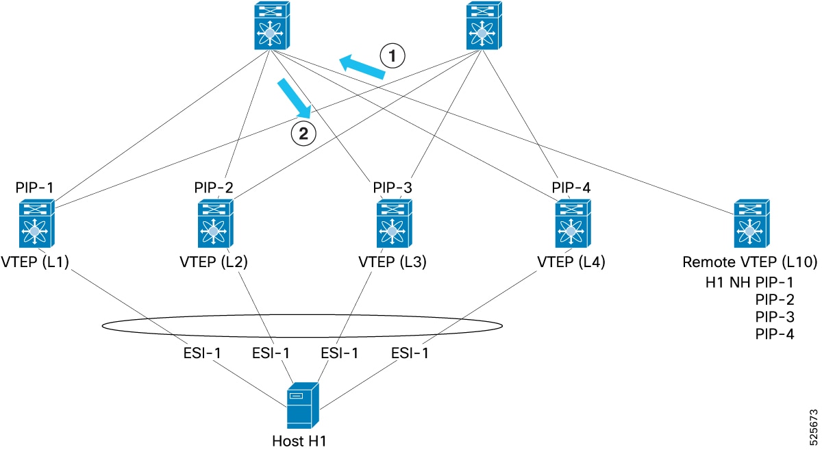
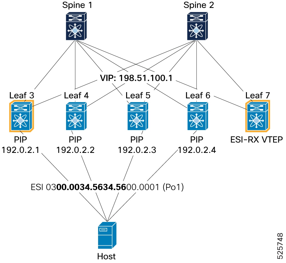
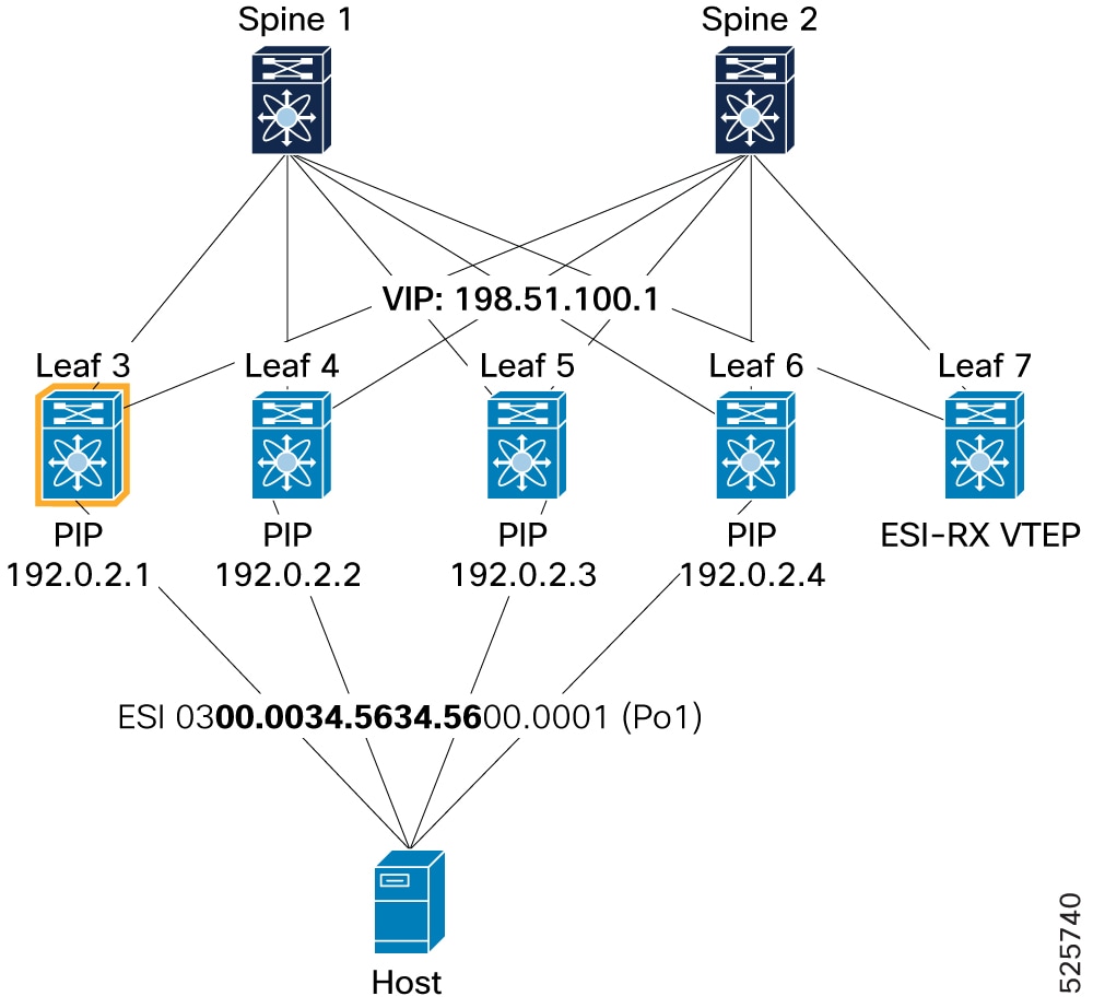
ESI multi-homing PIP mode examples
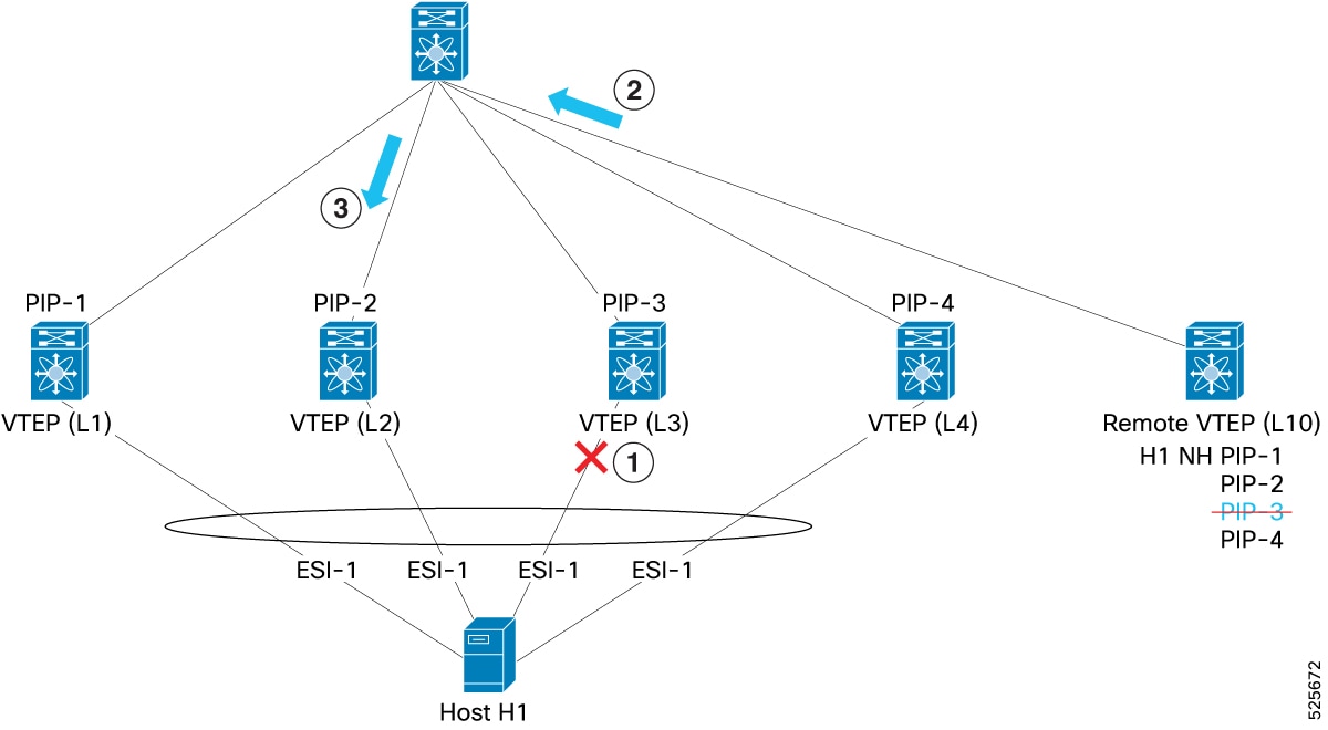
Consider four ESI peer VTEPs (L1, L2, L3, and L4), with their respective unique PIP addresses (PIP-1, PIP-2, PIP-3, and PIP-4). A host (H1), is multi-homed to all four of these VTEPs. A remote VTEP (L10), learns that H1 is reachable through PIP-1, PIP-2, PIP-3, and PIP-4. When L10 sends traffic to H1, it uses hashing to select one of these PIPs (PIP-3) and encapsulates the traffic, setting PIP-3 as the outer VXLAN destination IP. If the ESI on L3 experiences failure, the BGP EVPN control plane informs L10. L10 then removes PIP-3 from its list of paths for H1 and subsequently distributes traffic to H1 using ECMP, selecting from PIP-1, PIP-2, and PIP-4, in this example PIP-2 is selected.
-
L10 sends packet to Host with destination IP, PIP-3
-
Spine forwards packet to L3
-
ESI goes down on L3
-
L10 makes adjustment to send traffic to PIP-2 (and not PIP-3)
-
Spine forwards packet to L2
ESI multi-homing VIP modes
ESI multi-homing VIP modes are operational modes in VXLAN EVPN fabric that:
-
Identify the reachability of a multi-homed host through a common Anycast IP address (VIP) configured across all participating ESI peer VTEPs.
-
Provide a highly resilient and scalable solution for host connectivity in VXLAN EVPN fabrics.
-
Simplify the forwarding logic for remote VTEPs by presenting a single, stable IP address for multi-homed hosts.
How ESI multi-homing VIP modes work
-
VIP assignment : Each ESI-VTEP is configured with a unique PIP. Additionally, all ESI-VTEPs within a given ESI cluster are configured with the same VIP.
-
Host reachability advertisement : A multi-homed host connects to multiple ESI peer VTEPs. The BGP EVPN control plane advertises the host's reachability to remote VTEPs via the common VIP rather than the individual PIPs.
-
Traffic forwarding : When a remote VTEP sends traffic to the multi-homed host, it encapsulates the traffic with the VIP as the destination IP. The spine switches perform an ECMP hash to select one of the available ESI peer VTEPs. Once the traffic reaches the selected ESI peer VTEP, the VTEP forwards it to the multi-homed host.
-
Fault tolerance : If an ESI goes down, the remote VTEP continues to send traffic to the host using the VIP. If the traffic lands on the VTEP whose ESI is down, the L2FRR mechanism forwards the traffic to one of the VTEPs where ESI is UP.
-
Impact on VIP or PIP switching : Remote VTEPs dynamically switch between VIP forwarding mode (when two or more multi-homed ESI-VTEPs are up) and PIP forwarding mode (when only a single ESI-VTEP is active) based on BGP-EVPN signaling.
Note |
A switch can operate in either VIP mode or PIP mode, but not both simultaneously. Ensure all ESI peers operate in the same mode to avoid inconsistencies. VIP or Anycast next-hop is specified in draft evpn-anycast-aliasing . |
Steady state and failure scenarios
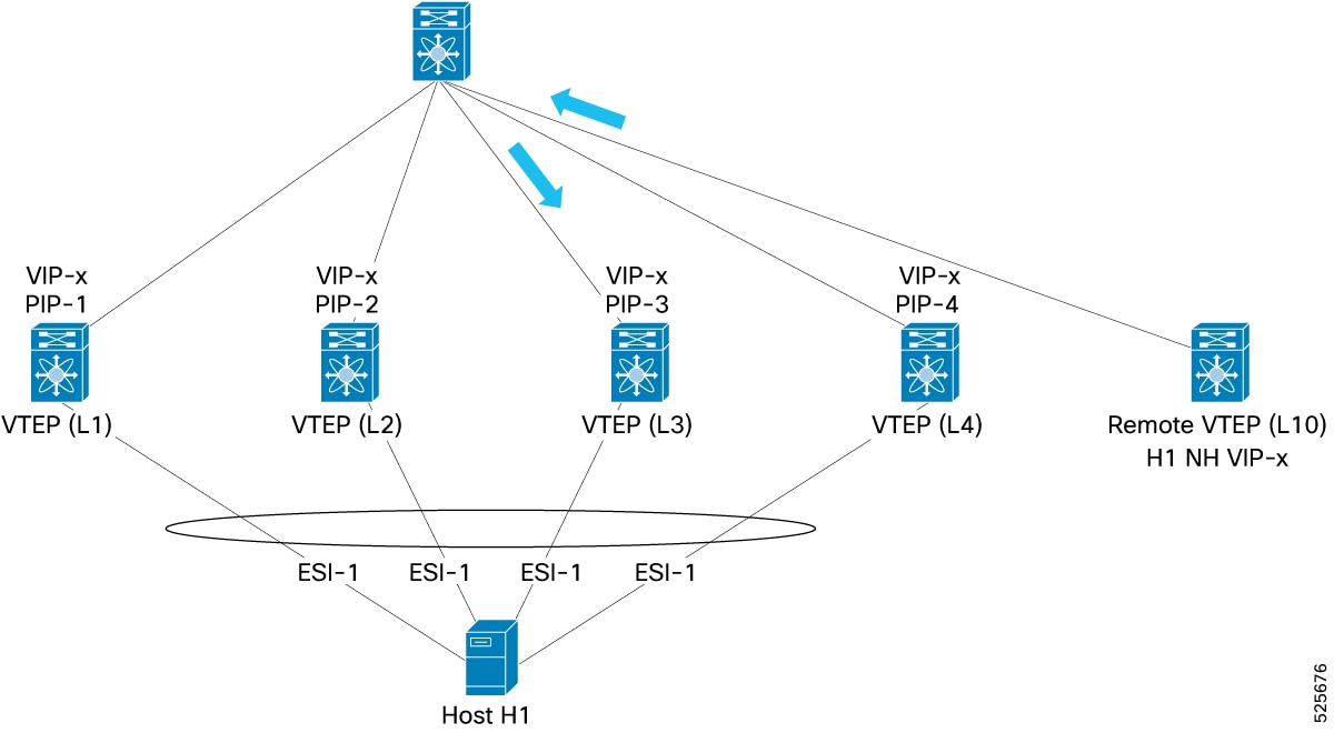
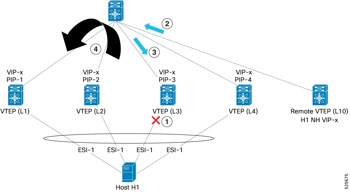
Consider four ESI peers (L1, L2, L3, and L4) with individual PIPs and a common VIP (VIP-x). A remote VTEP (L10) learns that host H1 is reachable through VIP-x and encapsulates traffic to H1 with VIP-x as the outer destination. The spine switch uses ECMP to select one VTEP (e.g., L3). If the ESI on L3 fails, L10 continues to send traffic to VIP-x, and L3 uses L2FRR to redirect the traffic to an active VTEP (e.g., L1) without requiring L10 to update its forwarding state.
-
L10 sends packet to Host with Dest-IP VIP-x
-
Spine selects L3 for VIP-x and forwards to L3
-
ESI goes down on L3
-
L10 continues to send with VIP-x
-
Traffic reaches L3 where ESI is down
-
L3 uses L2FRR to redirect the traffic to L1 where ESI-1 is still up.
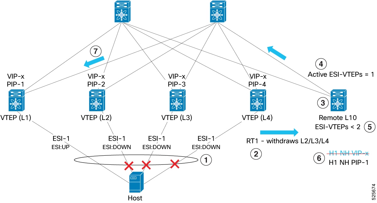
VIP to PIP transition
-
Multiple ESI links (L2, L3, and L4) go down, causing several ESI failures to be detected.
-
BGP-EVPN Route Type 1 (RT-1) withdrawals are signaled across the fabric to indicate these changes.
-
Remote VTEP L10 receives updates about the ESI status changes.
-
As a result, the number of active ESI-VTEPs drops to one—only L1 remains active.
-
L10 detects that fewer than two ESI-VTEPs are active and triggers a transition from VIP-next-hop mode to PIP-next-hop mode.
-
The next-hop is updated from the shared VIP-x to the individual IP address of L1 (PIP-1).
-
All traffic is now sent directly to L1 without ECMP distribution among multiple VTEPs.
-
Since there is only one active ESI-VTEP, no fast reroute is needed; traffic reaches the remaining active VTEP (L1) directly.
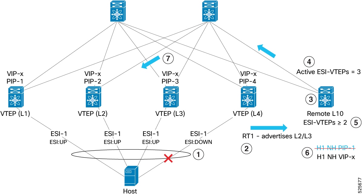
PIP to VIP transition
-
ESI recovery occurs as the L2 and L3 ESI links come back online.
-
BGP-EVPN Route Type 1 (RT1) advertisements are signaled across the fabric to announce the recovery.
-
Remote VTEP L10 receives updates about the restored ESI status.
-
The count of active ESI-VTEPs increases to three, where L1, L2, and L3 are all active.
-
L10 detects that two or more ESI-VTEPs are now active and initiates a transition from PIP-next-hop mode to VIP-next-hop mode.
-
The next-hop is updated from the individual IP address of L1 (PIP-1) to the shared anycast IP (VIP-x).
-
With ECMP load balancing enabled, traffic is distributed across L1, L2, and L3.
-
As a result, bandwidth utilization is optimized through even traffic distribution.
Layer 2 Fast Reroute
Layer 2 Fast Reroute (L2FRR) is a network protection mechanism that:
-
minimizes traffic disruption and prevents traffic from being discarded during failure conditions of an ESI connection,
-
ensures that traffic destined for a multi-homed host, that might still arrive at a failed ESI switch, is redirected to an active ESI peer within the same cluster, and
-
enhances network resilience by maintaining traffic flow during convergence or when remote VTEPs are not yet updated.
L2FRR Operational Principles
When an ESI connection to a multi-homed host fails on a specific ESI switch, the L2FRR functionality is activated on that failing switch. The switch internally redirects any traffic that still reaches it for the affected multi-homed host to another healthy ESI peer switch in the same multi-homing cluster.
Assign a unique identifier to the fast reroute packet. This allows you to handle fast reroute packets in specific ways. For example, if a packet has already been fast rerouted once, it should not be fast rerouted again to another ESI-VTEP in case of double failures. To ensure unique identification, assign a special Source IP, called the fast reroute anycast source IP, to the fast reroute packet. For detailed configuration steps, see the Enable EVPN ESI multi-homing section.
Note |
Ensure that you configure the fast reroute anycast source IP address uniquely on all the switches that are part of the same ESI multi-homing cluster. |
L2FRR operates differently depending on the mode:
-
In PIP mode : If an ESI connection goes down, the BGP-EVPN control plane signals this event. During the convergence period, traffic from remote VTEPs might still be directed to the failed switch. L2FRR detects the failure and redirects this traffic to an active ESI peer. For each ESI, a reroute peer is elected in a round-robin fashion from the active peer list. This prevents traffic loss while remote VTEPs update their forwarding paths. For more information, see ESI multi-homing PIP mode examples.
-
In VIP mode : Remote VTEPs always send traffic to the common VIP for the multi-homed host. The spine switch is responsible for ECMP'ing traffic to the underlying active VTEPs. If traffic is directed to a failed ESI switch, L2FRR intercepts the traffic and redirects it to an active ESI peer, ensuring traffic is never discarded. For more information, see Steady state and failure scenarios.
Designated Forwarder elections
Designated Forwarder (DF) elections are network mechanisms in multi-homing VXLAN EVPN fabrics that:
-
determine which VTEP forwards BUM traffic to a shared Ethernet Segment,
-
avoid redundant forwarding and network loops, and
-
support configurable methods, such as per-flow hashing and modulo-based selection, to optimize traffic handling and scalability.
How DF elections work
DF elections are crucial in multi-homing environments to prevent duplicate forwarding of BUM traffic. DF elections select one VTEP from those connected to an Ethernet Segment to forward such traffic. Other VTEPs do not forward BUM traffic for that segment.
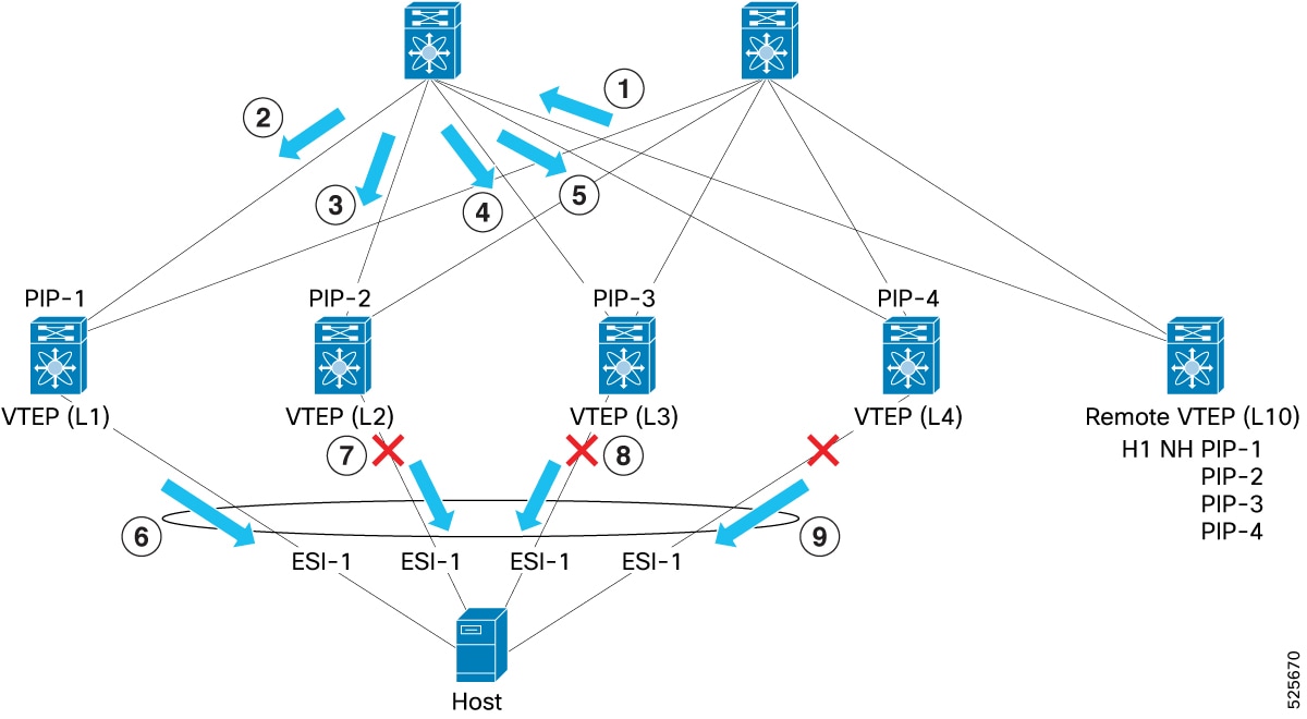
(1): VTEP-L10 sends broadcast packet (for example, ARP)
(2), (3), (4), and (5): Spine sends to all VTEPs (L1-L4)
In this example, the fabric uses a multicast underlay. If the underlay uses IR, the Remote VTEP (L10) sends a separate copy of the packet to each ESI-VTEP. In both cases, broadcast data packet reaches all the ESI-VTEPs.
(6): L1 is the DF and sends packet to Host
(7), (8), and (9): L2, L3, and L4 are non-DFs and do not forward the packet to Host
The following list describes the supported DF election methods:
-
Per-flow (Packet Hash-based) method (default) : This is the default method where the DF is determined based on hashing the fields of each incoming packet. Each ESI peer independently performs this hash using Ethernet Segment route type (Type-4) information to divide the hash result equally among ESI peer VTEPs. This method offers excellent scalability for L2VNIs by providing better BUM flow distribution.
-
Modulo method (fallback) : This method assigns DF responsibility based on a modulo calculation using Ethernet Segment routes. It distributes VLANs equally among ESI peer-VTEPs, ensuring only one ESI-VTEP is responsible for forwarding traffic to the multi-homed host for each VLAN. It acts as a fallback mechanism if members of the same Ethernet Segment are configured with different DF election modes.
Supported DF election methods
Per-flow (Packet Hash-based) method (default)
-
Mechanism: This is the default method. The DF is determined based on hashing the fields of each incoming packet. Each ESI peer independently performs this hash.
The DF election algorithm per-flow uses the Ethernet Segment route type (Type-4).
The BGP route Type-4 helps you determine the number of ESI-VTEPs for an ESI and their respective loopback IPs that are associated with each ESI. Based on this information from route Type-4, the hash result is divided equally among the ESI peer VTEPs.
After calculating the packet hash, each VTEP determines whether it must forward the packet to the multi-homed host or if another ESI peer is responsible.
All VTEPs participating in the ESI peer cluster must use the same per-flow DF. If any VTEPs do not use per-flow DF, the cluster uses modulo-based DF election.
-
Traffic handling:
-
Each ESI peer receives BUM traffic, which is based on PIP, from the remote VTEP, regardless of the underlay replication mode (ingress replication or multicast).
-
Upon receiving the traffic, each ESI peer calculates the packet hash.
-
Based on the hash result, one peer is designated as the forwarder for that specific flow and sends the traffic to the multi-homed host.
-
Other peers not designated for that flow drop the traffic towards the multi-homed host.
-
If traffic is received from an ESI peer (for example, from another VTEP in the same ESI cluster), the ESI ports are pruned to prevent loops.
-
-
Scalability: This method offers excellent scalability for L2VNIs because the DF election is determined per-flow, rather than per-VLAN, and provides better BUM flow distribution across the multi-homed VTEPs.
Modulo method (fallback)
-
Mechanism: This method utilizes Ethernet Segment routes, which are also employed in Anycast BGWs and multi-homing scenarios. It assigns DF responsibility based on a modulo calculation.
The BGP route Type-4 helps you determine the number of ESI-VTEPs for an ESI and their respective loopback IPs. Based on this information, the VLANs are distributed equally among the ESI peer-VTEPs. In this way, for each VLAN, only one ESI-VTEP is responsible to forward the traffic to the multi-homed host and is called the DF for that VLAN. This process is the modulo method.
-
Fallback use case: The modulo method acts as a fallback DF election mechanism if members of the same Ethernet Segment are configured with different DF election modes.
-
Scalability: This method typically requires the use of alternative multicast indices (Alt-mcindex), which are derived from a shared global multicast index pool. This can impact the overall scale of supported VLANs and IGMP or MLD groups on the platform.
-
Traffic handling: When BUM traffic arrives at an ESI-VTEP and the Modulo Method is used:
-
The ESI-VTEP forwards the BUM traffic to all orphan ports associated with that VLAN, regardless of whether it is the DF for that VLAN.
-
The ESI-VTEP then evaluates whether to send the BUM traffic to the ESI port, which connects to the multi-homed host. If the ESI-VTEP is the DF for that VLAN, it forwards the traffic to the multi-homed host through the ESI port. If it is not the DF, it does not send the traffic to the multi-homed host.
This process ensures that only one ESI-VTEP sends BUM traffic to the multi-homed host, preventing duplication.
-
EVPN EAD-EVI routes
EVPN EAD-EVI route is a type of BGP EVPN route that:
-
advertises per-EVI information to enable flexible communication between Ethernet segments in an EVPN network,
-
supports standards compliance for multi-homed host scenarios, and
-
enables interoperability while being disabled by default in Cisco NX-OS implementations unless explicitly enabled.
In the current Cisco NX-OS implementation, when a host is learned on one ESI-VTEP, it is advertised to the peer ESI VTEPs. The peer ESI VTEPs also send out a Re-Origination (RO) to the fabric. This approach ensures that a remote VTEP has all the information needed to route traffic through multiple paths to a multi-homed host. Since RO is mandatory in NX-OS, a remote VTEP does not need to use EAD-EVI information to determine the ESI VTEPs for a multi-homed host. The EAD-EVI route remains available for standards compliance.
Type-2 route re-origination
A Type-2 route re-origination is an EVPN mechanism that:
-
enables VTEP peers to originate new copies of peer-synced MAC and MAC-IP routes,
-
ensures redundancy for multi-homed hosts in ESI clusters, and
-
prevents loss of reachability for remote VTEPs if a local VTEP or Ethernet Segment goes down.
Type-2 route re-origination example
A host (H1) is multi-homed to VTEPs L1, L2, L3, and L4. If H1’s MAC and MAC-IP routes are learned locally on L1, then L1 advertises MAC and MAC-IP reachability. As part of the same ESI cluster, L2, L3, and L4 treat those as peer-synced routes and program reachability to the local Ethernet Segment. L2, L3, and L4 also re-originate the MAC and MAC-IP routes and advertise them in EVPN update messages.
A remote VTEP, L10, learns that H1 is reachable through PIP-1, PIP-2, PIP-3, and PIP-4 (in PIP mode), or through a virtual IP (VIP) with 4 paths from L1–L4 (in VIP mode).
If re-origination is not used, remote VTEP L10 receives only a single path (from L1) for H1’s reachability. If the ES goes down on L1 and the other VTEPs have not yet learned H1’s MAC and MAC-IP routes, IP traffic to H1 is lost until the routes are learned elsewhere. With re-origination, the remaining VTEPs prevent this traffic loss by advertising alternate paths.
Ethernet Segment delay-restore timers
The Ethernet Segment (ES) delay-restore timer is a mechanism for managing the recovery of Ethernet Segments in EVPN that:
-
activates when an NVE interface flaps, causing all associated ESIs to go down.
-
delays the restoration of ESIs, bringing them back online only after the timer expires.
-
prevents traffic from being attracted to the VIP while hardware programming is in progress.
The VIP interface remains down until the ES delay-restore timer expires. Once all ESI POs are operational, the VIP interface activates. After the ES delay-restore timer ends, a 480-second VIP anycast delay-restore timer starts to ensure the VIP interface eventually activates even if a PO fails to come online.
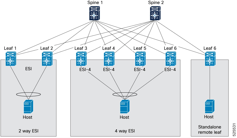
How ESI multi-homing topologies work
ESI multi-homing topologies are data center network designs that provide redundancy and load balancing through the use of Ethernet Segment Identifiers. These designs support scalable deployments by allowing multiple ESI interfaces in various configurations, including 2-way, 4-way, and butterfly topologies.
-
ESI multi-homing with 2-way, 4-way and standalone remote leaf
-
Butterfly topology
-
Interoperability with different ESI multi-homing solutions
Summary
The key components involved in the process are:
-
Spine switches (Spine 1 and Spine 2) : The spine switches interconnect all leaf switches and provide high-speed forwarding between network segments.
-
Leaf switches (Leaf 1-10) : These switches act as the access layer, connecting directly to end hosts and providing connectivity to the spine layer. Leaf switches participate in ESI groups to support multi-homed hosts.
-
ESI : A logical construct that groups multiple physical links from a host to different leaf switches, enabling multi-homing for redundancy and load balancing.
-
Hosts : End devices (for example: servers, virtual machines) that require network connectivity and can be configured for single-homed or multi-homed attachment.
-
2-way ESI configuration : A setup where a host is multi-homed to two leaf switches, providing dual-path redundancy. This configuration is also called dual homing.
-
4-way ESI configuration : A setup where a host is multi-homed to four leaf switches, offering enhanced redundancy and greater load-balancing capabilities.
-
Standalone remote leaf (Leaf 7) : A leaf switch that provides single-homed connectivity to a host, operating independently without multi-homing.
-
vPC or vPC fabric peering multi-homing : Represents various multi-homing approaches, including physical link aggregation, vPC fabric peering, and vPC for redundant host attachments.
Workflow
These stages describe the ESI multi-homing process:
-
Host multi-homing and ESI group formation
- A host connects its physical interfaces to two or more leaf switches, creating redundant physical paths.
- Leaf switches configured with the same ESI for a specific host form a logical group and exchange control plane information to coordinate traffic forwarding.
-
Traffic handling and load balancing
- Ingress traffic is received by an active leaf switch in the ESI group and forwarded to the spine layer and local interfaces.
- Egress BUM traffic is managed by the ESI mechanism to ensure only one designated leaf switch forwards traffic to the host, preventing duplicates.
- The ESI mechanism balances traffic across active links; if a link or leaf fails, remaining members take over to ensure continuous connectivity.
Result
Ethernet Segments provide high availability, redundancy, and efficient load balancing for your hosts in a spine-leaf network architecture, ensuring robust and scalable data center connectivity.
Guidelines and limitations for ESI multi-homing
This section outlines the requirements, constraints, and supported behaviors for configuring ESI multi-homing on Cisco NX-OS.
Supported releases and platforms
|
Release |
Platforms |
||
|---|---|---|---|
|
10.6(1)F |
Cisco Nexus 9300-FX2/FX3/GX/GX2/H2R/H1 Series switches Cisco Nexus 9500 Series switches with 9700-GX/FX3 line cards
|
Supported and unsupported features
|
Feature |
Supported Release |
Comments |
|---|---|---|
|
Multi-site |
10.6(1)F |
Multi-homing on the BGW is not supported, including the stretching of an ESI across sites. However, hosts connected to an ESI within a single site remain reachable from other sites. |
|
DF algorithm |
10.6(1)F |
Supported |
|
Host mobility |
10.6(1)F |
Supported |
|
Multicast underlay and ingress replication for IPv4 |
10.6(1)F |
Supported |
|
IGMP and MLD Snooping, Type-7 and 8 |
10.6(1)F |
Supported |
|
Full STP support |
10.6(1)F |
Supported |
|
PIP and VIP NH |
10.6(1)F |
Supported |
|
VXLAN PBR |
10.6(1)F |
Supported. However, PBR next-hop configurations are not supported when the next hop is reachable via a 3-way or 4-way ESI in VIP mode. |
|
N-way ESI |
10.6(1)F |
4-way ESI is supported, but configurations exceeding 4-way (for example, 5-way or more) are not supported. |
|
Butterfly topology |
10.6(1)F |
Only PIP mode is supported. VIP mode is not supported. |
|
ESI Type-0 and 3 |
10.6(1)F |
Supported |
|
VXLAN TE |
- |
Not supported |
|
TRM |
- |
Not supported |
|
ISSU on EoR |
- |
Not supported |
|
IPv6 underlay |
- |
Not supported |
|
DSVNI |
- |
Not supported |
|
Redundancy mode |
10.6(1)F |
Active/Active - Supported Active/Standby - Not supported |
|
GPO SGACL for ESI multi-homing |
10.6(3)F |
For more information, see Micro-segmentation for VXLAN fabrics using group policy option (GPO) |
Feature limitations
-
vPC or vPC fabric peering can coexist. However, each VTEP operates in either vPC-VTEP or ESI-VTEP mode, not both simultaneously.
-
Beginning with Cisco NX-OS Release 10.6(1)F, link-local addresses are advertised on devices with ESI multi-homing enabled. Only devices participating in the given Ethernet Segment accept the route. Devices that are not part of the Ethernet Segment drop the route.
-
The fast reroute anycast source IP address must be unique across the fabric to handle the fast reroute packet appropriately.
For example, if a packet has already undergone fast rerouting once, do not reroute it again to another ESI-VTEP in the event of double failures. Assign a specific source IP address, known as the fast reroute anycast source IP, to reroute the packet and ensure unique identification. For more information about configuration, see the Enable EVPN ESI multi-homing section.
-
ISSU is supported for VTEPs part of a multi-homing cluster.
-
The ESI Multi-homing feature requires TCAM carving of the region ing-flow-redirect . Save the configuration and reload the switch to apply the changes.
Note
The ing-flow-redirect TCAM region must be explicitly carved to a size of 512.
-
Ethernet Segment and ESI configurations are supported only on Layer 2 port channel interfaces.
-
The new L3VNI (vni vnid l3 ) must be configured on all ESI peers.
-
All multi-homed hosts across ESIs must be configured to the same set of ESI-VTEPs, and the esi-id should be consistent on each relevant port-channel; discrepancies are not flagged by the consistency checker.
-
A secondary IP address (VIP) is required only when either vPC or EVPN ESI multi-homing is configured.
Configuration requirements
-
The maximum-path must be configured under the EVPN address-family on all participating NX-OS nodes. This allows BGP to select multiple paths for EAD per ES and EAD per EVI routes. Remote VTEPs require this configuration for ESI-RX functionality, supporting multi-homing on ESI-VTEPs.
-
To detect duplicate host addresses and set host move detection parameters, use these commands:
-
l2rib dup-host-mac-detection num-of-host-moves dup-detection-timeout
-
fabric forwarding dup-host-ip-addr-detection num-of-host-moves dup-detection-timeout
For more information, see the Duplicate host detection mechanisms for IP and MAC addresses section.
-
-
If a user performs clear ip arp force-delete on a VRF, and then clear mac address-table dynamic, the number of ARP entries on the ESI nodes may become unsynchronized. To prevent this inconsistent state, synchronize the ARP entries on all ESI nodes by using the ip arp suppression-cache download remote vlan vlan_id command.
-
Ensure that MAC suppression is enabled on all VTEPs in the fabric.
-
L2FRR is functionally the same as "bounce." This distinction is important because the command show nve ethernet-segment refers to the peer as "Bounce Peer" rather than "L2FRR Peer."
PIP or VIP mode
-
If re-origination occurs, you do not need to send the EAD/EVI route. By default, the EAD/EVI route is disabled for both PIP and VIP modes. Enable EAD/EVI using the ead-evi route command if required. This configuration optimizes the network by reducing the number of routes. For configuration details, see the EVPN EAD-EVI routes section.
-
An L2FRR entry is programmed for the duration of the ESI downtime. This action redirects traffic to another functional ESI peer.
-
In PIP mode, FRR must be configured to ensure that L2FRR functions correctly.
-
In VIP next-hop mode, traffic may land on a VTEP whose ESI is down. This occurs because the remote VTEP continues to use the VIP as the next hop.
-
Mode transition behavior (from the standpoint of a remote VTEP)
-
The VTEP operates in VIP next-hop mode when ESI is active on two or more VTEP peers.
-
It transitions to PIP next-hop mode when only one ESI peer remains active for a multi-homed host.
-
The system reverts to VIP next-hop mode if two or more ESI peers become active again.
For more information, see the ESI multi-homing PIP modes and ESI multi-homing VIP modes sections.
-
-
In a VIP topology, the VIP address is used as the source IP for L2FRR (bounce) traffic if an explicit FRR IP address is not configured.
-
In a PIP topology, the configured FRR IP address is used as the source IP for L2FRR (bounce) traffic.
Enable EVPN ESI multi-homing
Before you begin
-
Ensure TCAM carving is configured. If not, use the following command and reload the switch:
hardware access-list tcam region ing-flow-redirect 512 -
Ensure Layer 3 VNIs are configured with new L3VNI (vni vnid l3 ). For more information, see Configure VXLAN BGP EVPN.
-
Configure maximum-path under the EVPN address-family on the Cisco NX-OS nodes to enable BGP to select multiple paths for EAD per ES and EAD per EVI routes.
Leaf-7(config)# router bgp 1
Leaf-7(config-router)# address-family l2vpn evpn
Leaf-7(config-router-af)# maximum-paths ibgp 4
Leaf-7(config-router)# vrf 3001
Leaf-7(config-router-vrf)# address-family ipv4 unicast
Leaf-7(config-router-vrf-af)# maximum-paths ibgp 4
EVPN ESI multi-homing provides Ethernet-segment redundancy and supports multi-homing on ESI-VTEPs. Cisco NX-OS allows either vPC-based or ESI-based multi-homing, but not both at the same time. Enabling ESI multi-homing does not affect path-list or route processing for existing Type-1 and Type-2 routes.
Note |
Cisco NX-OS supports either vPC-based EVPN multi-homing or ESI-based EVPN multi-homing, but not both simultaneously. |
Procedure
|
Step 1 |
Enter global configuration mode. Example: |
|
Step 2 |
Enable EVPN ESI multi-homing and configure system MAC address. |
|
Step 3 |
Configure DF election settings. |
|
Step 4 |
Enable EAD-EVI route advertisement. Use the ead-evi route command. By default, this is disabled. Example: |
|
Step 5 |
Configure Ethernet segment delay restore time. Use the ethernet-segment delay-restore time secs command. The range is 30 to 1000 seconds, with a default of 180 seconds. Example: |
|
Step 6 |
Configure fast reroute anycast source IP (L2FRR). Use the frr anycast source-ip ip-address command.
Example: |
|
Step 7 |
Exit EVPN multi-homing configuration mode. Example: |
|
Step 8 |
Enable core-links tracking on L3 interface toward spine. In interface configuration mode, use the evpn multihoming core-tracking command. This step is required for the ES to be UP. Example: |
|
Step 9 |
Verify configuration. Example: |
EVPN ESI multi-homing is enabled and operational.
Configure ESI under a port channel interface
Before you begin
-
Ensure that the port channel is configured as a Layer 2 port channel.
-
Configure the global system MAC before inheriting it in a Type-3 ESI.
Procedure
|
Step 1 |
Enter global configuration mode. Use the configure terminal command. Example: |
|||||||||||||||
|
Step 2 |
Enter interface mode. Use the interface port-channel value command. Example: |
|||||||||||||||
|
Step 3 |
Enable ES configuration. Use the ethernet-segment command. Example: |
|||||||||||||||
|
Step 4 |
Configure ESI under port channel. Use the esi value | esi system-mac [ system-mac ] local-discriminator command. The supported ESI route types are:
|
|||||||||||||||
|
Step 5 |
Exit until you reach configuration mode. Use the exit command. Example: |
|||||||||||||||
|
Step 6 |
Configure the NVE interface. Use the interface nve value command. Example: |
|||||||||||||||
|
Step 7 |
(Optional) Configure Anycast VIP interface. Use the source-interface loopback Id anycast loopback Id command in NVE interface. To remove the NVE source and anycast loopback interface mapping, use the no source-interface loopback Id anycast loopback Id command.
Example: |
|||||||||||||||
|
Step 8 |
(Optional) Verify the configurations. |
The port channel is successfully configured with the specified ESI, enabling it for multi-homing in an EVPN environment. The system recognizes the ESI configuration, and verification commands confirm that the ESI and related interfaces are operational, supporting redundancy and resiliency for Layer 2 services.
What to do next
-
Verify connectivity and redundancy.
-
Monitor the status of the ESI and port channel interfaces and confirm they remain in the "Up" state.
Verification commands for ESI multi-homing configuration
Use these commands to view ESI multi-homing configuration information and verify the ESI multi-homing setup on your device.
|
Command |
Purpose |
|---|---|
|
show bgp evi |
Displays BGP EVPN routes learned by the switch. |
|
show bgp l2vpn evpn route-type value |
Displays BGP route type state. |
|
show l2route topology all |
Displays a comprehensive view of the Layer 2 forwarding table with information about MAC addresses, associated VLANs, and next-hops. |
|
show l2route evpn mac all |
Displays all learned MAC addresses within the EVPN domain. |
|
show l2route evpn mac-ip all |
Displays all MAC and IP addresses that the switch learned through BGP EVPN. |
|
show l2route evpn imet all |
Displays the MAC addresses, their associated VNI, and the VTEP from which the addresses were learned. |
|
show l2route evpn fl all |
Displays all Layer 2 EVPN routes the switch learned, both locally and remotely. |
|
show l2route evpn ead all |
Displays information about all EAD routes in the EVPN routing table. |
|
show l2route evpn ethernet-segment { esi esi-id | all }[ bgp | vxlan ] [ detail ] |
Displays information about Ethernet Segments in an EVPN environment, specifically within a VXLAN fabric. |
|
show l2route evpn ethernet-segment { esi esi-id | all }[ detail ] |
Displays information about Ethernet Segments in an EVPN environment on the switch. |
|
show l2route smet { topology topo-id | all } [ detail ] |
Displays information about Layer 2 Multicast (SMET) routes within a VXLAN EVPN fabric. |
|
show l2route report-sync { topology topo-id | all } [ esi esi-id ] [ detail ] |
Displays details about the synchronization of Layer 2 EVPN routes reports. |
|
show l2route leave-sync { topology topo-id | all } [ esi esi-id ] [ detail ] |
Displays details about leave synchronization for Layer 2 EVPN routes. |
|
show nve interface nve1 detail |
Displays information about the Network Virtualization Edge interface nve1. |
|
show nve ethernet-segment |
Displays detailed information about configured NVE Ethernet segments. |
|
show nve core-links |
Displays details about the configured Ethernet segments, including their status and associated VNIs. |
|
show [ip | ipv6] [igmp | mld] snooping groups [vlan] [vlan ID] |
Displays the corresponding group address, version, group type, and port list information, depending on IGMP or MLD. |
|
show ipv6 mld groups |
Displays information about MLD snooping. |
|
show ip igmp snooping evpn |
Displays information about the IP IGMP snooping configuration and statistics. |
|
show ipv6 mld snooping evpn |
Displays information about the IPv6 MLD snooping configuration. |
|
show ip igmp snooping evpn esi |
Displays the IGMP snooping configuration and status for the EVPN context, including ESI details, port-channel, ESI ID, and type. |
|
show ipv6 mld snooping evpn esi |
Displays information about MLD snooping within the EVPN context, including ESI details, port-channel, ESI ID, and type. |
|
show ip igmp snooping evpn report-sync |
Displays IGMP snooping and EVPN report-sync information for VLAN, VNI, group, source, local/remote, and version flags. |
|
show ipv6 mld snooping evpn report-sync |
Displays IPv6 IGMP snooping and EVPN report-sync information for VLAN, VNI, group, source, local/remote, and version flags. |
|
show ip igmp snooping evpn leave-sync |
Displays the IGMP snooping leave synchronization status in an EVPN environment. |
|
show ipv6 mld snooping evpn leave-sync |
Displays the IPv6 IGMP snooping leave synchronization status in an EVPN environment. |
|
show ip igmp snooping remote groups |
Displays the remote IGMP group address, version, group type, and port list at VLAN level. |
|
show ipv6 mld snooping remote groups |
Displays the remote MLD group address, version, group type, and port list at VLAN level. |
|
show bgp l2vpn evpn route-type 7 |
Displays the state of BGP L2VPN EVPN route Type-7 and the report-sync routing table information for all VRFs. |
|
show bgp l2vpn evpn route-type 8 |
Displays the state of BGP L2VPN EVPN route Type-8 and leave-sync routing table information for all VRFs. |
|
show ip adjacency vrf vrf-id |
Displays IP adjacency information for a specific VRF. |
|
show ipv6 adjacency vrf vrf-id |
Displays IPv6 adjacency information within a specific VRF. |
|
show ip arp vrf vrf-id |
Displays the ARP table for a specific VRF instance. |
|
show ip arp suppression-cache vlan vlan-id |
Displays ARP entries being suppressed for the specified VLAN, including IP address, MAC address, and interface for each entry. |
|
show ipv6 neighbor vrf vrf_name |
Displays the IPv6 neighbors learned via NDP within the specific VRF. |
|
show ipv6 icmp neighbor vrf vrf_name |
Displays the IPv6 neighbor entries for a specified VRF, typically learned via ICMPv6 Neighbor Discovery. |
|
show mac address-table dynamic |
Displays all MAC addresses learned dynamically by the switch, along with associated interface and VLAN. |
|
show mac address-table count es all |
Displays the total number of MAC addresses learned for each Ethernet Segment. |
|
show forwarding route ipaddr platform |
Displays the routing table, including learned routes, next hops, and associated interfaces. |
ESI multi-homing configuration examples
Provides comprehensive configuration steps and verification commands for implementing ESI multi-homing in both PIP and VIP modes to ensure network redundancy and traffic optimization.
Pre configure for ESI multi-homing
Before configuring ESI multi-homing, ensure the following steps are complete:
-
Create a TCAM carving. TCAM carving is required to enable the ESI-MH feature.
Leaf-3(config)# hardware access-list tcam region ing-flow-redirect 512 -
Enable maximum-paths. The maximum-paths is required on ESI-RX VTEPs to enable ECMP.
Leaf-7(config)# router bgp 1
Leaf-7(config-router)# address-family l2vpn evpn
Leaf-7(config-router-af)# maximum-paths ibgp 4
Leaf-7(config-router)# vrf 3001
Leaf-7(config-router-vrf)# address-family ipv4 unicast
Leaf-7(config-router-vrf-af)# maximum-paths ibgp 4
Configure ESI multi-homing
-
Enable ESI multi-homing with system MAC. The system-mac is required to generate the Ethernet Segment ID (ESI).
Leaf-3(config)# evpn multihoming Leaf-3(config-evpn-mh)# system-mac 0000.3456.3456 -
Enable L2 Fast Reroute (L2FRR). L2FRR is designed to minimize traffic disruption during ESI failure conditions. This command is mandatory in PIP mode but optional in VIP mode, where VIP is used as the anycast source IP.
Leaf-3(config-evpn-mh)# frr anycast source-ip 203.0.113.1 -
Enable core links tracking on L3 interfaces to check the operational state of the core links. When all core links are down, ESI port-channel interfaces also go down to avoid traffic null route.
Leaf-3(config)# interface Ethernet1/1-2
Leaf-3(config-if)# evpn multihoming core-tracking
Enable Ethernet Segment
-
Enable Ethernet Segment (ES) on Port-Channel interface.
Leaf-3(config)# interface port-channel 1 Leaf-3(config-if)# ethernet-segment -
Configure ESI:
-
Type 0: Arbitrary 9-byte values.
Leaf-3(config-if-ethernet-segment)# esi 0021.0000.0000.2100.0222 -
Type 3: System MAC address (6 bytes) and Local Discriminator (3 bytes). For more details of Type-3 system MAC options, see the Configure ESI under a port channel interface section.
Leaf-3(config-if-ethernet-segment)# esi system-mac
-
Enable ESI multi-homing PIP or VIP mode
-
Configuration for PIP mode:
-
Create loopback interface with NVE source IP.
Leaf-3(config)# interface loopback 1 Leaf-3(config-if)# ip address 192.0.2.1/32 -
Enable PIP on NVE interface.
Leaf-3(config)# interface nve1
Leaf-3(config-if-nve)# source-interface loopback1
-
-
Configuration for VIP mode:
-
Create loopback interface with NVE source IP.
Leaf-3(config)# interface loopback 1 Leaf-3(config-if)# ip address 192.0.2.1/32 -
Create loopback interface with Anycast VIP.
Leaf-3(config)# interface loopback 2 Leaf-3(config-if)# ip address 198.51.100.1/32 -
Enable Anycast VIP on NVE interface.
Leaf-3(config)# interface nve1
Leaf-3(config-if-nve)# source-interface loopback1 anycast loopback2
-
Verification of VIP mode
This section details the verification steps for ESI multi-homing VIP Mode. The validation covers the advertisement and synchronization of EVPN Type-1 (EAD-ES) and Type-2 (MAC-IP) routes across local and remote VTEPs using a VIP.
-
EVPN EAD-ES route advertisements
-
Local route (from Leaf 3): Shows that Leaf 3, as an ESI node, advertises its local EAD-ES route (Type-1) with a VIP Next-Hop (198.51.100.1) to its ESI peers (Leaf 4, Leaf 5 and Leaf 6) and BGP. The
show l2route evpn ead esandshow bgp l2vpn evpn route-type 1outputs confirm the local origination and the VIP as the egress next-hop.Figure 11. Verification of VIP mode – Local route 
Example for BGP component: Leaf3# show bgp l2vpn evpn route-type 1 Route Distinguisher: 192.0.13.1:7817 (EAD-ES [0300.0034.5634.5600.0001 7817]) BGP routing table entry for [1]:[0300.0034.5634.5600.0001]:[0xffffffff]/152, version 154 Paths: (1 available, best #1) Flags: (0x000002) (high32 00000000) on xmit-list, is not in l2rib/evpn Multipath: eBGP iBGP Advertised path-id 1 Path type: local, path is valid, is best path, no labeled nexthop AS-Path: NONE, path locally originated 192.0.2.1 (metric 0) from 0.0.0.0 (192.0.13.1) Origin IGP, MED not set, localpref 100, weight 32768 Received label 0 Extcommunity: RT:1:2001001 RT:1:2001002 ENCAP:8 ESI:32:000000 Tunnel Encapsulation Attribute: Type: 8 Length: 12 Sub Type: 6 Egress Nexthop: 198.51.100.1 Path-id 1 advertised to peers: 192.0.2.21 192.0.2.22Example for L2RIB component: Leaf3# show l2route evpn ead es Topology ID Prod ESI Sent To Num PLs Flags ------------- ------ ------------------------- ---------- -------- ---------- 4294967294 VXLAN 0300.0034.5634.5600.0001 BGP 0 A Next-Hops: 192.0.2.1 VIP Next-Hop: 198.51.100.1 -
Remote route (received by Leaf3): Shows Leaf 3 receiving Type-1 routes from other remote ESI peers (Leaf 4, Leaf 5, and Leaf 6) within the 4-way ESI cluster. These routes also indicate the VIP (198.51.100.1) as the egress next-hop, and Leaf3's L2RIB correctly populates the next-hops for these remote ESI members.
Figure 12. Verification of VIP mode – Remote route 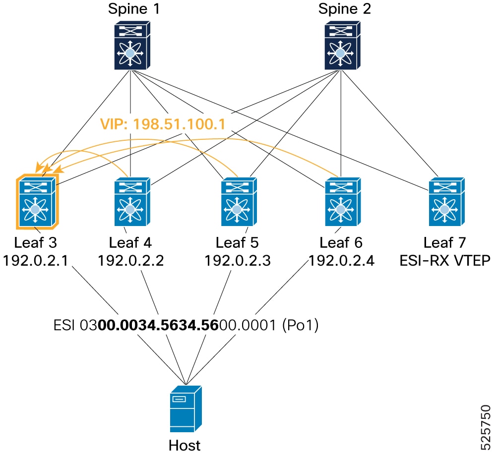
Example for BGP component: Leaf3# show bgp l2vpn evpn route-type 1 Route Distinguisher: 192.0.13.1:65534 (L2VNI 0)<SNIP> Path type: internal, path is valid, not best reason: Router Id, multipath, no labeled nexthop, in rib Imported from 192.0.16.1:7821:[1]:[0300.0034.5634.5600.0001]:[0xffffffff]/152 AS-Path: NONE, path sourced internal to AS 192.0.2.4 (metric 9) from 192.0.2.21 (192.0.2.21) Origin IGP, MED not set, localpref 100, weight 0 Received label 0 Extcommunity: RT:1:2002001 RT:1:2002002 ENCAP:8 ESI:32:000000 Originator: 192.0.16.1 Cluster list: 192.0.2.21 Tunnel Encapsulation Attribute: Type: 8 Length: 12 Sub Type: 6 Egress Nexthop: 198.51.100.1 Advertised path-id 1 Path type: internal, path is valid, is best path, no labeled nexthop, in rib Imported from 192.0.14.1:7821:[1]:[0300.0034.5634.5600.0001]:[0xffffffff]/152 AS-Path: NONE, path sourced internal to AS 192.0.2.2 (metric 9) from 192.0.2.21 (192.0.2.21) Origin IGP, MED not set, localpref 100, weight 0 Received label 0 Extcommunity: RT:1:2002001 RT:1:2002002 ENCAP:8 ESI:32:000000 Originator: 192.0.14.1 Cluster list: 192.0.2.21 Tunnel Encapsulation Attribute: Type: 8 Length: 12 Sub Type: 6 Egress Nexthop: 198.51.100.1 Path type: internal, path is valid, not best reason: Router Id, multipath, no labeled nexthop, in rib Imported from 192.0.2.10:7821:[1]:[0300.0034.5634.5600.0001]:[0xffffffff]/152 AS-Path: NONE, path sourced internal to AS 192.0.2.3 (metric 9) from 192.0.2.21 (192.0.2.21) Origin IGP, MED not set, localpref 100, weight 0 Received label 0 Extcommunity: RT:1:2002001 RT:1:2002002 ENCAP:8 ESI:32:000000 Originator: 192.0.2.10 Cluster list: 192.0.2.21 Tunnel Encapsulation Attribute: Type: 8 Length: 12 Sub Type: 6 Egress Nexthop: 198.51.100.1Example for L2RIB component: Leaf3# show l2route evpn ead es Topology ID Prod ESI Sent To Num PLs Flags ------------- ------ ------------------------- ---------- -------- ---------- 4294967294 BGP 0300.0034.5634.5600.0001 - 0 A Next-Hops: 192.0.2.2 192.0.2.3 192.0.2.4 -
Remote VTEP (ESI-RX, Leaf 7): Verifies that a remote VTEP (Leaf 7) receives Type-1 EAD-ES route advertisements from all four ESI nodes (Leaf 3, Leaf 4, Leaf 5, and Leaf 6) within the 4- way ESI cluster, with the VIP (198.51.100.1) consistently being the egress next-hop. Leaf 7's L2RIB reflects all four VTEP IPs as next-hops for the ESI.
Figure 13. Verification of VIP mode - Remote VTEP (ESI-RX) 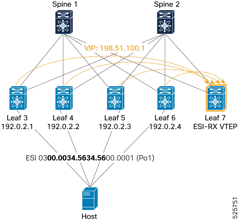
Example for BGP component: Leaf 7# show bgp l2vpn evpn route-type 1 Route Distinguisher: 192.0.17.1:65534 (L2VNI 0) <SNIP> Path type: internal, path is valid, not best reason: Router Id, multipath, no labeled nexthop, in rib Imported from 192.0.16.1:7821:[1]:[0300.0034.5634.5600.0002]:[0xffffffff]/152 AS-Path: NONE, path sourced internal to AS 192.0.2.4 (metric 9) from 192.0.2.21 (192.0.2.21) Origin IGP, MED not set, localpref 100, weight 0 Received label 0 Extcommunity: RT:1:2002001 RT:1:2002002 ENCAP:8 ESI:32:000000 Originator: 192.0.16.1 Cluster list: 192.0.2.21 Tunnel Encapsulation Attribute: Type: 8 Length: 12 Sub Type: 6 Egress Nexthop: 198.51.100.1 Path type: internal, path is valid, not best reason: Router Id, multipath, no labeled nexthop, in rib Imported from 192.0.14.1:7821:[1]:[0300.0034.5634.5600.0002]:[0xffffffff]/152 AS-Path: NONE, path sourced internal to AS 192.0.2.2 (metric 9) from 192.0.2.21 (192.0.2.21) Origin IGP, MED not set, localpref 100, weight 0 Received label 0 Extcommunity: RT:1:2002001 RT:1:2002002 ENCAP:8 ESI:32:000000 Originator: 192.0.14.1 Cluster list: 192.0.2.21 Tunnel Encapsulation Attribute: Type: 8 Length: 12 Sub Type: 6 Egress Nexthop: 198.51.100.1 Advertised path-id 1 Path type: internal, path is valid, is best path, no labeled nexthop, in rib Imported from 192.0.13.1:7821:[1]:[0300.0034.5634.5600.0002]:[0xffffffff]/152 AS-Path: NONE, path sourced internal to AS 192.0.2.1 (metric 9) from 192.0.2.21 (192.0.2.21) Origin IGP, MED not set, localpref 100, weight 0 Received label 0 Extcommunity: RT:1:2002001 RT:1:2002002 ENCAP:8 ESI:32:000000 Originator: 192.0.13.1 Cluster list: 192.0.2.21 Tunnel Encapsulation Attribute: Type: 8 Length: 12 Sub Type: 6 Egress Nexthop: 198.51.100.1 Path type: internal, path is valid, not best reason: Router Id, multipath, no labeled nexthop, in rib Imported from 192.0.2.10:7821:[1]:[0300.0034.5634.5600.0002]:[0xffffffff]/152 AS-Path: NONE, path sourced internal to AS 192.0.2.3 (metric 9) from 192.0.2.21 (192.0.2.21) Origin IGP, MED not set, localpref 100, weight 0 Received label 0 Extcommunity: RT:1:2002001 RT:1:2002002 ENCAP:8 ESI:32:000000 Originator: 192.0.2.10 Cluster list: 192.0.2.21 Tunnel Encapsulation Attribute: Type: 8 Length: 12 Sub Type: 6 Egress Nexthop: 198.51.100.1Example for L2RIB component: Leaf 7# show l2route evpn ead es Topology ID Prod ESI Sent To Num PLs Flags ------------- ------ ------------------------- ---------- -------- ---------- 4294967294 BGP 0300.0034.5634.5600.0001 - 2 A Next-Hops: 192.0.2.1 192.0.2.2 192.0.2.3 192.0.2.4
-
-
Verification of NVE Ethernet Segment
Confirms the Ethernet Segment (ESI: 0300.0034.5634.5600.0001) on Leaf3 is "Up" and associated with port-channel1. The show nve ethernet-segmentandshow nve interface nve 1detail commands on Leaf 3 confirm the configuration of the Anycast IP: 198.51.100.1 and list all four ESI members (192.0.2.1, 192.0.2.2, 192.0.2.3, 192.0.2.4) in the Designated Forwarder (DF) list. The NVE interface detail also shows the Anycast-Interface as loopback2 (secondary: 198.51.100.1).Figure 14. VIP mode -NVE Ethernet Segment verifications 
!Shows NVE status Leaf3# show nve ethernet-segment summary ESI Parent interface ES State ------------------------------ ------------------ ---------- 0300.0034.5634.5600.0001 port-channel1 Up !Shows ES status and ES configuration information Leaf3# show nve ethernet-segment ESI: 0300.0034.5634.5600.0001 Parent interface: port-channel1 ES State: Up Port-channel state: Up NVE Interface: nve1 NVE State: Up Host Learning Mode: control-plane Anycast IP: 198.51.100.1 Active Vlans: 1001-1002 DF Vlans: Active VNIs: 2001001-2001002 DF BDs: N/A DF VNIs: N/A Number of ES members: 4 My ordinal: 0 DF timer start time: 00:00:00 DF timer expiry: 16:05:31 Config State: config-applied DF List: 192.0.2.1 192.0.2.2 192.0.2.3 192.0.2.4 Bounce peer : 192.0.2.4 ES route added to L2RIB: True EAD/ES routes added to L2RIB: True EAD/EVI route timer age: not running [Disabled] EAD/EVI timer duration: 00:05:00 ESI type: Ether-segment ESI DF election mode: Per-flow !Shows ES configuration information in detial Leaf3# show nve interface nve 1 detail Interface: nve1, State: Up, encapsulation: VXLAN VPC Capability: VPC-VIP-Only [not-notified] Local Router MAC: 4880.0290.0727 Host Learning Mode: Control-Plane Source-Interface: loopback1 (primary: 192.0.2.1) Anycast-Interface: loopback2 (secondary: 198.51.100.1) Source Interface State: Up Anycast Interface State: Up ESI multihoming anycast-restore time left: 0 seconds Virtual RMAC Advertisement: No NVE Flags: Interface Handle: 0x49000001 Source Interface hold-down-time: 180 Source Interface hold-up-time: 30 Remaining hold-down time: 0 seconds Virtual Router MAC: 0200.6701.8601 Interface state: nve-intf-add-complete ESI multihoming delay-restore time: 180 seconds ESI multihoming delay-restore time left: 0 seconds ESI multihoming FRR anycast source IP: 203.0.113.1 Fabric convergence time: 135 seconds Fabric convergence time left: 0 seconds -
EVPN Type-2 Route Advertisement (MAC-IP)
-
Local VTEP to ESI peers (peer sync): Demonstrates a host (MAC: 0010.0100.1301, IP: 10.1.13.1) learned locally on Leaf 5. Leaf 5 then advertises this Type-2 route as "locally originated" with its ESI. Other ESI peers (Leaf 3, Leaf 4, and Leaf 6) receive this route as "Peer Synced" (
PSflag in L2RIB), indicating they learned it from a peer within the same ESI.Figure 15. Verification of VIP mode - Local VTEP to ESI peers (peer sync) 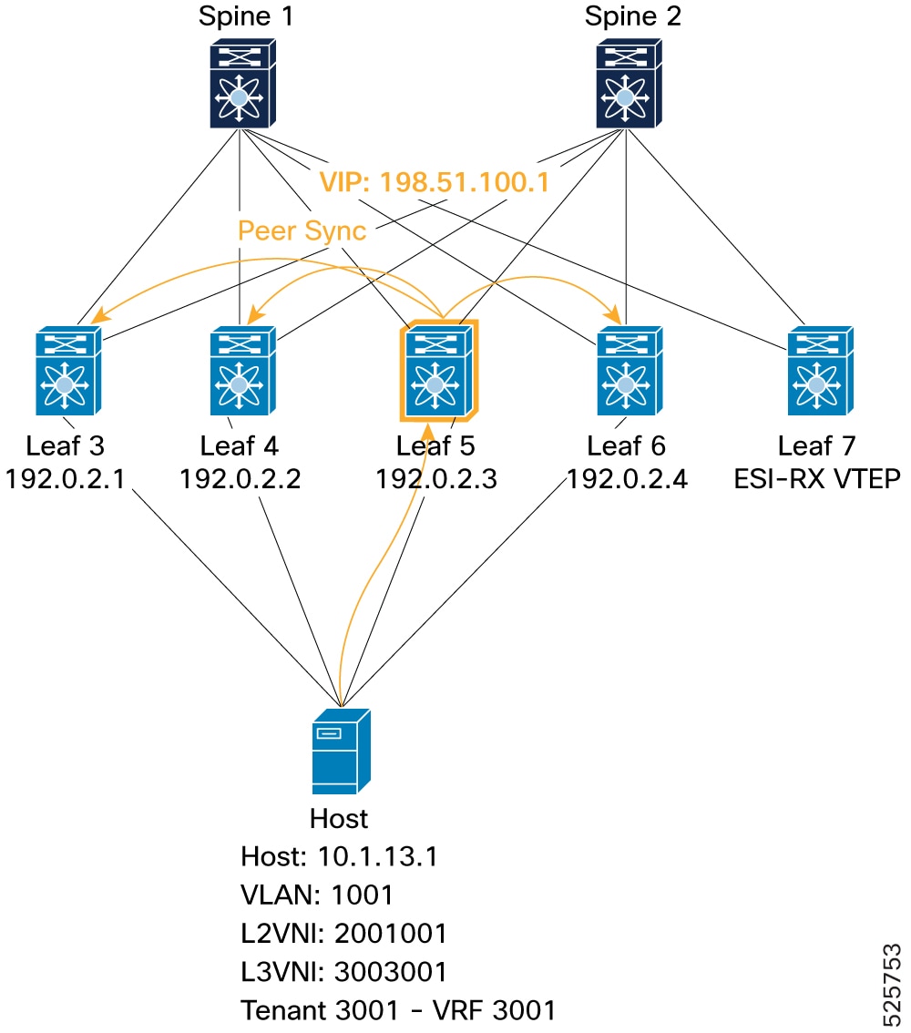
L2FM: Leaf5# show mac address-table vlan 1001 VLAN MAC Address Type age Secure NTFY Ports ---------+-----------------+--------+---------+------+----+------------------ C 1001 0010.0100.1301 dynamic NA F F Po1ARP: Leaf5# show ip arp vrf 3001 Address Age MAC Address Interface Flags 10.1.13.1 00:18:43 0010.0100.1301 Vlan1001L2RIB: Leaf5# show l2route evpn mac-ip evi 1001 detail Topology Mac Address Host IP Prod Flags Seq No Next-Hops ----------- -------------- ------------------------------------ ------ ----------------- ---------- -------------------------- 1001 0010.0100.1301 10.1.13.1 HMM L, 0 Local L3-Info: 3003001 Sent To: BGP ESI : 0300.0034.5634.5600.0001BGP: Leaf5# show bgp l2vpn evpn 10.1.13.1 Route Distinguisher: 192.0.2.10:33768 (L2VNI 2001001) <SNIP> Advertised path-id 1 Path type: local, path is valid, is best path, no labeled nexthop AS-Path: NONE, path locally originated 192.0.2.3 (metric 0) from 0.0.0.0 (192.0.2.10) Origin IGP, MED not set, localpref 100, weight 32768 Received label 2001001 3003001 Extcommunity: RT:1:2001001 RT:1:3003001 ENCAP:8 Router MAC:4880.0290.01af ESI: 0300.0034.5634.5600.0001 Path-id 1 advertised to peers: 192.0.2.21 192.0.2.22 -
ESI-MH Peer VTEP (Peer Sync): Shows successful peer synchronization of an EVPN Type-2 route for host 10.1.13.1 in one of 4-Way ESI MH node (example, Leaf 6). This is visible by the
mh_peer_syncedflag and "PS" flag.Figure 16. Verification of VIP mode - ESI-MH Peer VTEP (Peer Sync) 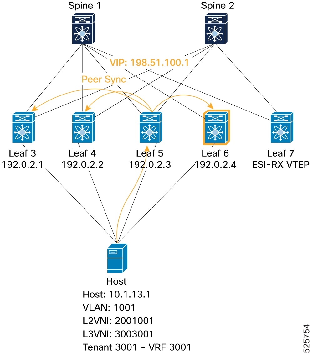
BGP: Leaf6# show bgp l2vpn evpn 10.1.13.1 Route Distinguisher: 192.0.16.1:33768 (L2VNI 2001001) <SNIP> Path type: internal, path is valid, not best reason: Local ESI, mh_peer_synced, no labeled nexthop, in rib Imported from 192.0.2.10:33768:[2]:[0]:[0]:[48]:[0010.0100.1301]:[32]:[10.1.13.1]/272 AS-Path: NONE, path sourced internal to AS 192.0.2.3 (metric 9) from 192.0.2.21 (192.0.2.21) Origin IGP, MED not set, localpref 100, weight 0 Received label 2001001 3003001 Extcommunity: RT:1:2001001 RT:1:3003001 ENCAP:8 Router MAC:4880.0290.01af Originator: 192.0.2.10 Cluster list: 192.0.2.21 ESI: 0300.0034.5634.5600.0001L2RIB: Leaf6# show l2route evpn mac-ip evi 1001 detail Topology Mac Address Host IP Prod Flags Seq No Next-Hops ----------- -------------- ------------------------------------ ------ ----------------- ---------- -------------------------- 1001 0010.0100.1301 10.1.13.1 BGP PS, 0 192.0.2.3 (Label: 2001001) Sent To: ARP ESI : 0300.0034.5634.5600.0001 Port-Channel Info: Po1 Encap-type:1 -
ESI-MH Remote VTEP (Re-Origination): Shows that an ESI member (Leaf 6) re-originates the Type-2 route for the locally learned host (even if learned via peer sync) to remote VTEPs. This is visible by a "locally originated" path from Leaf 6 itself, alongside the "Peer Synced" entry.
Figure 17. Verification of VIP mode - ESI-MH Remote VTEP (Re-Origination) 
BGP: Leaf6# show bgp l2vpn evpn 10.1.13.1 Route Distinguisher: 192.0.16.1:33768 (L2VNI 2001001) <SNIP> Advertised path-id 1 Path type: local, path is valid, is best path, no labeled nexthop AS-Path: NONE, path locally originated 192.0.2.4 (metric 0) from 0.0.0.0 (192.0.16.1) Origin IGP, MED not set, localpref 100, weight 32768 Received label 2001001 3003001 Extcommunity: RT:1:2001001 RT:1:3003001 SOO:192.0.16.1:256 ENCAP:8 Router MAC:f839.184d.48c7 ESI: 0300.0034.5634.5600.0001 Path-id 1 advertised to peers: 192.0.2.21 192.0.2.22L2RIB: Leaf6# show l2route evpn mac-ip evi 1001 detail Topology Mac Address Host IP Prod Flags Seq No Next-Hops ----------- -------------- ------------------------------------ ------ ----------------- ---------- -------------------------- 1001 0010.0100.1301 10.1.13.1 BGP PS, 0 192.0.2.4 (Label: 2001001) Sent To: ARP ESI : 0300.0034.5634.5600.0001 Port-Channel Info: Po1 Encap-type:1 1001 0010.0100.1301 10.1.13.1 HMM RO, 0 Local L3-Info: 3003001 Sent To: BGP ESI : 0300.0034.5634.5600.0001 -
Re-Origination Verification (Local VTEP): Verifies that the local VTEP (Leaf 5) receives re-originated Type-2 routes from other ESI members, marked with the mh_peer_reoriginatedflag in BGP.Figure 18. Verification of VIP mode - ESI-MH Local VTEP (Re-Origination) 
Leaf5# show bgp l2vpn evpn 10.1.13.1 Route Distinguisher: 192.0.2.10:33768 (L2VNI 2001001) <SNIP> Path type: internal, path is valid, not best reason: Router Id, mh_peer_reoriginated, no labeled nexthop Imported from 192.0.14.1:33768:[2]:[0]:[0]:[48]:[0010.0100.1301]:[32]:[10.1.13.1]/272 AS-Path: NONE, path sourced internal to AS 192.0.2.2 (metric 9) from 192.0.2.21 (192.0.2.21) Origin IGP, MED not set, localpref 100, weight 0 Received label 2001001 3003001 Extcommunity: RT:1:2001001 RT:1:3003001 SOO:192.0.14.1:256 ENCAP:8 Router MAC:f839.1867.df6b Originator: 192.0.14.1 Cluster list: 192.0.2.21 ESI: 0300.0034.5634.5600.0001 Path type: internal, path is valid, not best reason: Router Id, mh_peer_reoriginated, no labeled nexthop Imported from 192.0.16.1:33768:[2]:[0]:[0]:[48]:[0010.0100.1301]:[32]:[10.1.13.1]/272 AS-Path: NONE, path sourced internal to AS 192.0.2.4 (metric 9) from 192.0.2.21 (192.0.2.21) Origin IGP, MED not set, localpref 100, weight 0 Received label 2001001 3003001 Extcommunity: RT:1:2001001 RT:1:3003001 SOO:192.0.16.1:256 ENCAP:8 Router MAC:f839.184d.48c7 Originator: 192.0.16.1 Cluster list: 192.0.2.21 ESI: 0300.0034.5634.5600.0001 Path type: internal, path is valid, not best reason: Local ESI, mh_peer_reoriginated, no labeled nexthop Imported from 192.0.13.1:33768:[2]:[0]:[0]:[48]:[0010.0100.1301]:[32]:[10.1.13.1]/272 AS-Path: NONE, path sourced internal to AS 192.0.2.1 (metric 9) from 192.0.2.21 (192.0.2.21) Origin IGP, MED not set, localpref 100, weight 0 Received label 2001001 3003001 Extcommunity: RT:1:2001001 RT:1:3003001 SOO:192.0.13.1:256 ENCAP:8 Router MAC:4880.0290.0727 Originator: 192.0.13.1 Cluster list: 192.0.2.21 ESI: 0300.0034.5634.5600.0001 -
To Remote VTEP (ESI-RX, Leaf 7): Confirms that the remote ESI-RX VTEP (Leaf 7) receives the Type-2 route for the host (10.1.13.1) from all four ESI cluster members. All these paths consistently point to the VIP (198.51.100.1) as the egress next-hop. The L2RIB, MAC address table, IP route table, and FIB on Leaf 7 all show the host reachable via the VIP (198.51.100.1) through the NVE interface.
Figure 19. Verification of VIP mode - Remote VTEP (ESI-RX) 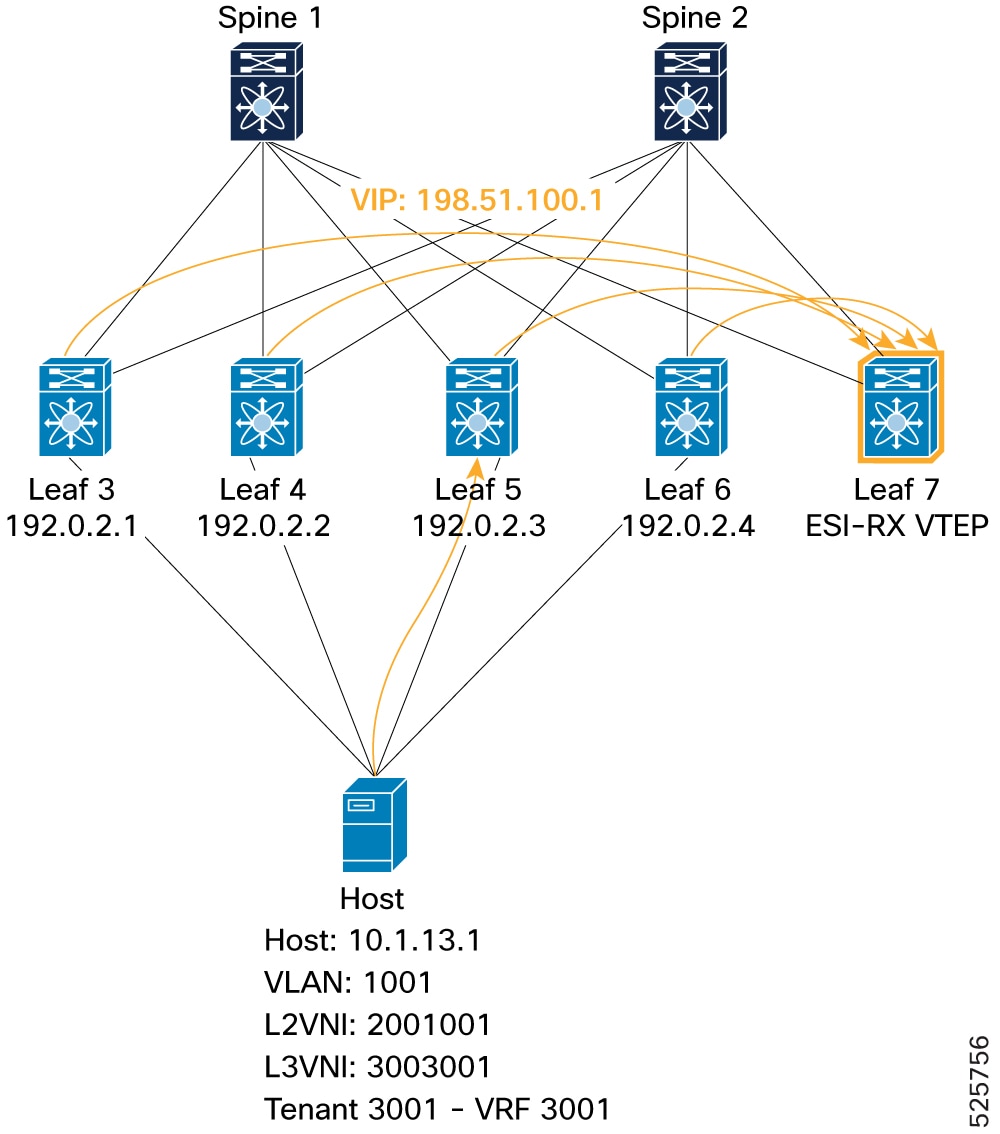
BGP: Leaf7# show bgp l2vpn evpn 10.1.13.1 Path type: internal, path is valid, not best reason: Router Id, no labeled nexthop, anycast NH Imported from 192.0.14.1:33768:[2]:[0]:[0]:[48]:[0010.0100.1301]:[32]:[10.1.13.1]/272 AS-Path: NONE, path sourced internal to AS 198.51.100.1 (metric 9) from 192.0.2.21 (192.0.2.21) Origin IGP, MED not set, localpref 100, weight 0 Received label 2001001 3003001 Extcommunity: RT:1:2001001 RT:1:3003001 SOO:192.0.14.1:256 ENCAP:8 Router MAC:f839.1867.df6b Originator: 192.0.14.1 Cluster list: 192.0.2.21 ESI: 0300.0034.5634.5600.0001 Path type: internal, path is valid, not best reason: Router Id, no labeled nexthop, anycast NH Imported from 192.0.16.1:33768:[2]:[0]:[0]:[48]:[0010.0100.1301]:[32]:[10.1.13.1]/272 AS-Path: NONE, path sourced internal to AS 198.51.100.1 (metric 9) from 192.0.2.21 (192.0.2.21) Origin IGP, MED not set, localpref 100, weight 0 Received label 2001001 3003001 Extcommunity: RT:1:2001001 RT:1:3003001 SOO:192.0.16.1:256 ENCAP:8 Router MAC:f839.184d.48c7 Originator: 192.0.16.1 Cluster list: 192.0.2.21 ESI: 0300.0034.5634.5600.0001 Advertised path-id 1 Path type: internal, path is valid, is best path, no labeled nexthop, in rib, anycast NH Imported from 192.0.13.1:33768:[2]:[0]:[0]:[48]:[0010.0100.1301]:[32]:[10.1.13.1]/272 AS-Path: NONE, path sourced internal to AS 198.51.100.1 (metric 9) from 192.0.2.21 (192.0.2.21) Origin IGP, MED not set, localpref 100, weight 0 Received label 2001001 3003001 Extcommunity: RT:1:2001001 RT:1:3003001 SOO:192.0.13.1:256 ENCAP:8 Router MAC:4880.0290.0727 Originator: 192.0.13.1 Cluster list: 192.0.2.21 ESI: 0300.0034.5634.5600.0001 Path type: internal, path is valid, not best reason: Router Id, no labeled nexthop, anycast NH Imported from 192.0.15.1:33768:[2]:[0]:[0]:[48]:[0010.0100.1301]:[32]:[10.1.13.1]/272 AS-Path: NONE, path sourced internal to AS 198.51.100.1 (metric 9) from 192.0.2.21 (192.0.2.21) Origin IGP, MED not set, localpref 100, weight 0 Received label 2001001 3003001 Extcommunity: RT:1:2001001 RT:1:3003001 ENCAP:8 Router MAC:4880.0290.01af Originator: 192.0.15.1 Cluster list: 192.0.2.21 ESI: 0300.0034.5634.5600.0001L2RIB: Leaf7# show l2route evpn mac-ip evi 1001 detail Topology Mac Address Host IP Prod Flags Seq No Next-Hops ----------- -------------- ------------------------------------ ------ ----------------- ---------- -------------------------- 1001 0010.0100.1301 10.1.13.1 BGP -- 0 198.51.100.1 (Label: 2001001) Sent To: ARP Encap-type:1L2FM Leaf7# show mac address-table vlan 1001 VLAN MAC Address Type age Secure NTFY Ports ---------+-----------------+--------+---------+------+----+------------------ C 1001 0010.0100.1301 dynamic NA F F nve1(198.51.100.1)URIB: Leaf7# show ip route 10.1.13.1 detail vrf 3001 10.1.13.1/32, ubest/mbest: 1/0 Extended Community: 0x1b 1c 01 03 65 01 0d 01 01 00 00 00 00 00 00 00 00 00 03 00 00 34 56 34 56 00 00 01 *via 198.51.100.1%default, [200/0], 00:56:42, bgp-1, internal, tag 1, segid: 3003001 tunnelid: 0x67018601 encap: VXLAN BGP-EVPN: VNI=3003001 (EVPN) client-specific data: 579 recursive next hop: 198.51.100.1/32%default extended route information: BGP origin AS 1 BGP peer AS 1FIB: Leaf7# show forwarding ipv4 route 10.1.13.1 vrf 3001 ------------------+-----------------------------------------+----------------------+-----------------+----------------- Prefix | Next-hop | Interface | Labels | Partial Install ------------------+-----------------------------------------+----------------------+-----------------+----------------- 10.1.13.1/32 198.51.100.1 nve1 vni: 3003001
-
Verification of PIP mode
This section details the verification steps for ESI multi-homing PIP Mode. The validation covers the advertisement and synchronization of EVPN Type-1 (EAD-ES) and Type-2 (MAC-IP) routes across local and remote VTEPs using a PIP.
-
EVPN EAD-ES route advertisements
-
Local route (from Leaf3): Shows how a local Leaf (Leaf 3) advertises its Type-1 EAD-ES route for ESI 0300.0034.5634.5600.0001 to its BGP peers (Spines). The command
show l2route evpn ead eson Leaf3 confirms the local route (Prod: VXLAN) with its next-hop. The commandshow bgp l2vpn evpn route-type 1on Leaf3 shows the locally originated Type-1 route with the correct ESI and next-hop.Figure 20. Verification of PIP mode – Local route 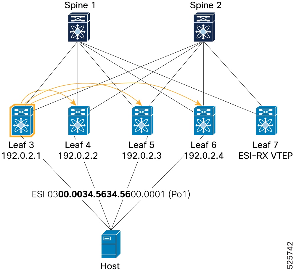
Example for BGP component: Leaf3# show bgp l2vpn evpn route-type 1 Route Distinguisher: 192.0.13.1:7817 (EAD-ES [0300.0034.5634.5600.0001 7817]) BGP routing table entry for [1]:[0300.0034.5634.5600.0001]:[0xffffffff]/152, version 154 Paths: (1 available, best #1) Flags: (0x000002) (high32 00000000) on xmit-list, is not in l2rib/evpn Multipath: eBGP iBGP Advertised path-id 1 Path type: local, path is valid, is best path, no labeled nexthop AS-Path: NONE, path locally originated 192.0.2.1 (metric 0) from 0.0.0.0 (192.0.13.1) Origin IGP, MED not set, localpref 100, weight 32768 Received label 0 Extcommunity: RT:1:2001001 RT:1:2001002 ENCAP:8 ESI:0:000000 Path-id 1 advertised to peers: 192.0.2.21 192.0.2.22Example for L2RIB component: Leaf3# show l2route evpn ead es Topology ID Prod ESI Sent To Num PLs Flags ------------- ------ ------------------------- ---------- -------- ---------- 4294967294 VXLAN 0300.0034.5634.5600.0001 BGP 0 A Next-Hops: 192.0.2.1 -
Remote route (received by Leaf 3): Shows how a Leaf (Leaf 3 ) receives Type-1 EAD-ES routes from its ESI peers (Leaf 4, Leaf 5, and Leaf 6) within a 4-way ESI cluster. The command
show bgp l2vpn evpn route-type 1on Leaf 3 displays multiple paths for the same ESI, originating from different ESI peers (192.0.2.2, 192.0.2.3, 192.0.2.4), indicating successful reception of remote routes. The commandshow l2route evpn ead eson Leaf 3 confirms the presence of these remote ESI routes (Prod: BGP) with multiple next-hops.Figure 21. Verification of PIP mode – Remote route 
Example for BGP component: Leaf3# show bgp l2vpn evpn route-type 1 Route Distinguisher: 192.0.13.1:65534 (L2VNI 0) BGP routing table entry for [1]:[0300.0034.5634.5600.0001]:[0xffffffff]/152, version 3434 Paths: (3 available, best #3) Flags: (0x000012) (high32 00000000) on xmit-list, is in l2rib/evpn, is not in HW Multipath: eBGP iBGP Path type: internal, path is valid, not best reason: Router Id, multipath, no labeled nexthop, in rib Imported from 192.0.2.10:7817:[1]:[0300.0034.5634.5600.0001]:[0xffffffff]/152 AS-Path: NONE, path sourced internal to AS 192.0.2.3 (metric 9) from 192.0.2.21 (192.0.2.21) Origin IGP, MED not set, localpref 100, weight 0 Received label 0 Extcommunity: RT:1:2001001 RT:1:2001002 ENCAP:8 ESI:0:000000 Originator: 192.0.2.10 Cluster list: 192.0.2.21 Path type: internal, path is valid, not best reason: Router Id, multipath, no labeled nexthop, in rib Imported from 192.0.16.1:7817:[1]:[0300.0034.5634.5600.0001]:[0xffffffff]/152 AS-Path: NONE, path sourced internal to AS 192.0.2.4 (metric 9) from 192.0.2.21 (192.0.2.21) Origin IGP, MED not set, localpref 100, weight 0 Received label 0 Extcommunity: RT:1:2001001 RT:1:2001002 ENCAP:8 ESI:0:000000 Originator: 192.0.16.1 Cluster list: 192.0.2.21 Advertised path-id 1 Path type: internal, path is valid, is best path, no labeled nexthop, in rib Imported from 192.0.14.1:7817:[1]:[0300.0034.5634.5600.0001]:[0xffffffff]/152 AS-Path: NONE, path sourced internal to AS 192.0.2.2 (metric 9) from 192.0.2.21 (192.0.2.21) Origin IGP, MED not set, localpref 100, weight 0 Received label 0 Extcommunity: RT:1:2001001 RT:1:2001002 ENCAP:8 ESI:0:000000 Originator: 192.0.14.1 Cluster list: 192.0.2.21Example for L2RIB component: Leaf3# show l2route evpn ead es Topology ID Prod ESI Sent To Num PLs Flags ------------- ------ ------------------------- ---------- -------- ---------- 4294967294 BGP 0300.0034.5634.5600.0001 - 0 A Next-Hops: 192.0.2.2 192.0.2.3 192.0.2.4 -
Remote VTEP (ESI-RX, Leaf 7): Verifies that a remote VTEP (Leaf 7), which is an ESI-RX VTEP, correctly receives Type-1 EAD-ES routes from all members of the 4-way ESI MH cluster (Leaf 3, Leaf4, Leaf 5, and Leaf 6). The command
show bgp l2vpn evpn route-type 1on Leaf 7 shows four available paths for the ESI, each originating from a different Leaf in the ESI cluster (192.0.2.1, 192.0.2.2, 192.0.2.3, 192.0.2.4). The commandsshow l2route evpn ead esandshow l2route evpn path-list all detailon Leaf 7 confirm the multiple next-hops for the ESI, indicating proper ECMP path installation.Figure 22. Verification of PIP mode – Remote VTEP (ESI-RX) 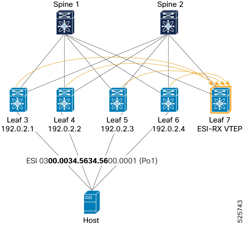
Example for BGP component: Leaf7# show bgp l2vpn evpn route-type 1 Route Distinguisher: 192.0.17.1:65534 (L2VNI 0) BGP routing table entry for [1]:[0300.0034.5634.5600.0001]:[0xffffffff]/152, version 2645 Paths: (4 available, best #3) Flags: (0x000012) (high32 00000000) on xmit-list, is in l2rib/evpn, is not in HW Multipath: eBGP iBGP Path type: internal, path is valid, not best reason: Router Id, multipath, no labeled nexthop, in rib Imported from 192.0.2.10:7817:[1]:[0300.0034.5634.5600.0001]:[0xffffffff]/152 AS-Path: NONE, path sourced internal to AS 192.0.2.3 (metric 9) from 192.0.2.21 (192.0.2.21) Origin IGP, MED not set, localpref 100, weight 0 Received label 0 Extcommunity: RT:1:2001001 RT:1:2001002 ENCAP:8 ESI:0:000000 Originator: 192.0.2.10 Cluster list: 192.0.2.21 Path type: internal, path is valid, not best reason: Router Id, multipath, no labeled nexthop, in rib Imported from 192.0.16.1:7817:[1]:[0300.0034.5634.5600.0001]:[0xffffffff]/152 AS-Path: NONE, path sourced internal to AS 192.0.2.4 (metric 9) from 192.0.2.21 (192.0.2.21) Origin IGP, MED not set, localpref 100, weight 0 Received label 0 Extcommunity: RT:1:2001001 RT:1:2001002 ENCAP:8 ESI:0:000000 Originator: 192.0.16.1 Cluster list: 192.0.2.21 Advertised path-id 1 Path type: internal, path is valid, is best path, no labeled nexthop, in rib Imported from 192.0.13.1:7817:[1]:[0300.0034.5634.5600.0001]:[0xffffffff]/152 AS-Path: NONE, path sourced internal to AS 192.0.2.1 (metric 9) from 192.0.2.21 (192.0.2.21) Origin IGP, MED not set, localpref 100, weight 0 Received label 0 Extcommunity: RT:1:2001001 RT:1:2001002 ENCAP:8 ESI:0:000000 Originator: 192.0.13.1 Cluster list: 192.0.2.21 Path type: internal, path is valid, not best reason: Router Id, multipath, no labeled nexthop, in rib Imported from 192.0.14.1:7817:[1]:[0300.0034.5634.5600.0001]:[0xffffffff]/152 AS-Path: NONE, path sourced internal to AS 192.0.2.2 (metric 9) from 192.0.2.21 (192.0.2.21) Origin IGP, MED not set, localpref 100, weight 0 Received label 0 Extcommunity: RT:1:2001001 RT:1:2001002 ENCAP:8 ESI:0:000000 Originator: 192.0.14.1 Cluster list: 192.0.2.21Example for L2RIB component: Leaf7# show l2route evpn ead es Topology ID Prod ESI Sent To Num PLs Flags ------------- ------ ------------------------- ---------- -------- ---------- 4294967294 BGP 0300.0034.5634.5600.0001 - 2 A Next-Hops: 192.0.2.1 192.0.2.2 192.0.2.3 192.0.2.4 Leaf7# show l2route evpn path-list all detail Topology ID Prod ESI ECMP Label Flags Client Ctx MACs Sent To ------------ ------ ------------------------- ---------- ------ ----------- ---------- ---------- 1001 None 0300.0034.5634.5600.0001 3 A 0 15 UFDM CP Next-Hops: 192.0.2.1 , 192.0.2.2 , 192.0.2.3 , 192.0.2.4 Gbl EAD Next-Hops: 192.0.2.1 (1,R) 192.0.2.2 (3,R) 192.0.2.3 (2,R) 192.0.2.4 (5,R) Res Next-Hops: 192.0.2.1 192.0.2.2 192.0.2.3 192.0.2.4 Bkp Next-Hops: Res Next-Hops from UFDM: 192.0.2.1 192.0.2.2 192.0.2.3 192.0.2.4 Bkp Next-Hops from UFDM:
-
-
Verification of NVE Ethernet Segment
Figure 23. PIP mode - NVE Ethernet Segment verification
-
NVE Ethernet Segment verification: Validates the state and configuration of the NVE Ethernet Segment on Leaf3. show nve ethernet-segment summary and show nve ethernet-segment on Leaf3 confirm the ESI 0300.0034.5634.5600.0001 is "Up," associated with port-channel1, and lists details like active VLANs/VNIs, DF (Designated Forwarder) list (192.0.2.1, 192.0.2.2, 192.0.2.3, 192.0.2.4), and ESI type. Leaf3# show nve ethernet-segment summary ESI Parent interface ES State ------------------------------ ------------------ ---------- 0300.0034.5634.5600.0001 port-channel1 Up Leaf3# show nve ethernet-segment ESI: 0300.0034.5634.5600.0001 Parent interface: port-channel1 ES State: Up Port-channel state: Up NVE Interface: nve1 NVE State: Up Host Learning Mode: control-plane Active Vlans: 1001-1002 DF Vlans: Active VNIs: 2001001-2001002 DF BDs: N/A DF VNIs: N/A Number of ES members: 4 My ordinal: 0 DF timer start time: 00:00:00 DF timer expiry: 17:11:42 Config State: config-applied DF List: 192.0.2.1 192.0.2.2 192.0.2.3 192.0.2.4 Bounce peer : 192.0.2.2 ES route added to L2RIB: True EAD/ES routes added to L2RIB: True EAD/EVI route timer age: not running [Disabled] EAD/EVI timer duration: 00:05:00 ESI type: Ether-segment ESI DF election mode: Per-flow -
NVE Interface Detail: Provides detailed information about the NVE interface (nve1) on Leaf3, including its state, encapsulation (VXLAN), host learning mode (control-plane), source interface (loopback1 with IP 192.0.2.1), and ESI multihoming delay-restore times. Leaf3# show nve interface nve 1 detail Interface: nve1, State: Up, encapsulation: VXLAN VPC Capability: VPC-VIP-Only [not-notified] Local Router MAC: 4880.0290.0727 Host Learning Mode: Control-Plane Source-Interface: loopback1 (primary: 192.0.2.1, secondary: 0.0.0.0) Source Interface State: Up Virtual RMAC Advertisement: No NVE Flags: Interface Handle: 0x49000001 Source Interface hold-down-time: 180 Source Interface hold-up-time: 30 Remaining hold-down time: 0 seconds Virtual Router MAC: N/A Interface state: nve-intf-add-complete ESI multihoming delay-restore time: 180 seconds ESI multihoming delay-restore time left: 0 seconds ESI multihoming FRR anycast source IP: 203.0.113.1 Fabric convergence time: 135 seconds Fabric convergence time left: 0 seconds
-
-
EVPN Type-2 route advertisement (MAC-IP)
-
Local VTEP to ESI peers (peer sync): Shows how a local VTEP (Leaf5) advertises a Type-2 MAC-IP route for a host (MAC 0010.0100.1301, IP 10.1.13.1) connected to the ESI. The commands
show mac address-tableandshow ip arpon Leaf 5 confirm the host's MAC and IP. The commandshow l2route evpn mac-ip evi 1001 detailon Leaf 5 shows the route as locally learned (Prod: HMM, Flags: L) and sent to BGP, with the associated ESI. The commandshow bgp l2vpn evpn 10.1.13.1on Leaf 5 confirms the locally originated Type-2 route, including its labels (L2VNI 2001001, L3VNI 3003001) and ESI.Figure 24. Verification of PIP mode - Local VTEP to ESI peers (peer sync) 
L2FM: Leaf5# show mac address-table vlan 1001 VLAN MAC Address Type age Secure NTFY Ports ---------+-----------------+--------+---------+------+----+------------------ C 1001 0010.0100.1301 dynamic NA F F Po1ARP: Leaf5# show ip arp vrf 3001 Address Age MAC Address Interface Flags 10.1.13.1 00:18:43 0010.0100.1301 Vlan1001L2RIB: Leaf5# show l2route evpn mac-ip evi 1001 detail Topology Mac Address Host IP Prod Flags Seq No Next-Hops ----------- -------------- ------------------------------------ ------ ----------------- ---------- -------------------------- 1001 0010.0100.1301 10.1.13.1 HMM L, 0 Local L3-Info: 3003001 Sent To: BGP ESI : 0300.0034.5634.5600.0001BGP: Leaf5# show bgp l2vpn evpn 10.1.13.1 Route Distinguisher: 192.0.2.10:33768 (L2VNI 2001001) <SNIP> Advertised path-id 1 Path type: local, path is valid, is best path, no labeled nexthop AS-Path: NONE, path locally originated 192.0.2.3 (metric 0) from 0.0.0.0 (192.0.2.10) Origin IGP, MED not set, localpref 100, weight 32768 Received label 2001001 3003001 Extcommunity: RT:1:2001001 RT:1:3003001 ENCAP:8 Router MAC:4880.0290.01af ESI: 0300.0034.5634.5600.0001 Path-id 1 advertised to peers: 192.0.2.21 192.0.2.22 -
ESI-MH Peer VTEP (Peer Sync): Shows how a peer VTEP (Leaf 6) receives the Type-2 route for the same host via peer synchronization. The command
show bgp l2vpn evpn 10.1.13.1on Leaf 6 shows the route imported from the peer (192.0.2.10, which is Leaf5's IP), with mh_peer_synced flag. The commandshow l2route evpn mac-ip evi 1001 detailon Leaf 6 shows the route received via BGP (Prod: BGP, Flags: PS) with the next-hop pointing to Leaf5's VTEP IP.Figure 25. Verification of PIP mode - ESI-MH Peer VTEP (Peer Sync) 
BGP: Leaf6# show bgp l2vpn evpn 10.1.13.1 Route Distinguisher: 192.0.16.1:33768 (L2VNI 2001001) <SNIP> Path type: internal, path is valid, not best reason: Local ESI, mh_peer_synced, no labeled nexthop, in rib Imported from 192.0.2.10:33768:[2]:[0]:[0]:[48]:[0010.0100.1301]:[32]:[10.1.13.1]/272 AS-Path: NONE, path sourced internal to AS 192.0.2.3 (metric 9) from 192.0.2.21 (192.0.2.21) Origin IGP, MED not set, localpref 100, weight 0 Received label 2001001 3003001 Extcommunity: RT:1:2001001 RT:1:3003001 ENCAP:8 Router MAC:4880.0290.01af Originator: 192.0.2.10 Cluster list: 192.0.2.21 ESI: 0300.0034.5634.5600.0001L2RIB: Leaf6# show l2route evpn mac-ip evi 1001 detail Topology Mac Address Host IP Prod Flags Seq No Next-Hops ----------- -------------- ------------------------------------ ------ ----------------- ---------- -------------------------- 1001 0010.0100.1301 10.1.13.1 BGP PS, 0 192.0.2.3 (Label: 2001001) Sent To: ARP ESI : 0300.0034.5634.5600.0001 Port-Channel Info: Po1 Encap-type:1 -
ESI-MH Remote VTEP (Re-Origination): Validates that a VTEP (Leaf6) within the ESI cluster re-originates the Type-2 route to remote VTEPs. The command
show bgp l2vpn evpn 10.1.13.1on Leaf 6 shows the locally originated path for 10.1.13.1 with its own VTEP IP (192.0.2.4) as the next-hop, indicating re-origination. The commandshow l2route evpn mac-ip evi 1001 detailon Leaf 6 shows both the peer-synced (PS) route and the re-originated (RO) route.Figure 26. Verification of PIP mode - ESI-MH Remote VTEP (Re-Origination) 
BGP: Leaf6# show bgp l2vpn evpn 10.1.13.1 Route Distinguisher: 192.0.16.1:33768 (L2VNI 2001001) <SNIP> Advertised path-id 1 Path type: local, path is valid, is best path, no labeled nexthop AS-Path: NONE, path locally originated 192.0.2.4 (metric 0) from 0.0.0.0 (192.0.16.1) Origin IGP, MED not set, localpref 100, weight 32768 Received label 2001001 3003001 Extcommunity: RT:1:2001001 RT:1:3003001 SOO:192.0.16.1:256 ENCAP:8 Router MAC:f839.184d.48c7 ESI: 0300.0034.5634.5600.0001 Path-id 1 advertised to peers: 192.0.2.21 192.0.2.22L2RIB: Leaf6# show l2route evpn mac-ip evi 1001 detail Topology Mac Address Host IP Prod Flags Seq No Next-Hops ----------- -------------- ------------------------------------ ------ ----------------- ---------- -------------------------- 1001 0010.0100.1301 10.1.13.1 BGP PS, 0 192.0.2.4 (Label: 2001001) Sent To: ARP ESI : 0300.0034.5634.5600.0001 Port-Channel Info: Po1 Encap-type:1 1001 0010.0100.1301 10.1.13.1 HMM RO, 0 Local L3-Info: 3003001 Sent To: BGP ESI : 0300.0034.5634.5600.0001 -
Re-Origination Verification (Local VTEP): Shows how a local VTEP (Leaf 5) receives re-originated Type-2 routes from other ESI peers (Leaf 3, Leaf 4, and Leaf6). The command show bgp l2vpn evpn 10.1.13.1on Leaf 5 displays multiple paths for the host, imported from various ESI peers, each flagged as mh_peer_reoriginated.Figure 27. Verification of PIP mode - ESI-MH Local VTEP (Re-Origination) 
Leaf5# show bgp l2vpn evpn 10.1.13.1 Route Distinguisher: 192.0.2.10:33768 (L2VNI 2001001) <SNIP> Path type: internal, path is valid, not best reason: Router Id, mh_peer_reoriginated, no labeled nexthop Imported from 192.0.14.1:33768:[2]:[0]:[0]:[48]:[0010.0100.1301]:[32]:[10.1.13.1]/272 AS-Path: NONE, path sourced internal to AS 192.0.2.2 (metric 9) from 192.0.2.21 (192.0.2.21) Origin IGP, MED not set, localpref 100, weight 0 Received label 2001001 3003001 Extcommunity: RT:1:2001001 RT:1:3003001 SOO:192.0.14.1:256 ENCAP:8 Router MAC:f839.1867.df6b Originator: 192.0.14.1 Cluster list: 192.0.2.21 ESI: 0300.0034.5634.5600.0001 Path type: internal, path is valid, not best reason: Router Id, mh_peer_reoriginated, no labeled nexthop Imported from 192.0.16.1:33768:[2]:[0]:[0]:[48]:[0010.0100.1301]:[32]:[10.1.13.1]/272 AS-Path: NONE, path sourced internal to AS 192.0.2.4 (metric 9) from 192.0.2.21 (192.0.2.21) Origin IGP, MED not set, localpref 100, weight 0 Received label 2001001 3003001 Extcommunity: RT:1:2001001 RT:1:3003001 SOO:192.0.16.1:256 ENCAP:8 Router MAC:f839.184d.48c7 Originator: 192.0.16.1 Cluster list: 192.0.2.21 ESI: 0300.0034.5634.5600.0001 Path type: internal, path is valid, not best reason: Local ESI, mh_peer_reoriginated, no labeled nexthop Imported from 192.0.13.1:33768:[2]:[0]:[0]:[48]:[0010.0100.1301]:[32]:[10.1.13.1]/272 AS-Path: NONE, path sourced internal to AS 192.0.2.1 (metric 9) from 192.0.2.21 (192.0.2.21) Origin IGP, MED not set, localpref 100, weight 0 Received label 2001001 3003001 Extcommunity: RT:1:2001001 RT:1:3003001 SOO:192.0.13.1:256 ENCAP:8 Router MAC:4880.0290.0727 Originator: 192.0.13.1 Cluster list: 192.0.2.21 ESI: 0300.0034.5634.5600.0001 -
To Remote VTEP (ESI-RX, Leaf 7): Confirms that a remote VTEP (Leaf 7) receives all Type-2 routes for the host from the 4-way ESI MH cluster. The command
show bgp l2vpn evpn 10.1.13.1on Leaf 7 shows four available paths for the host, each pointing to a different VTEP in the ESI cluster (192.0.2.1, 192.0.2.2, 192.0.2.3, 192.0.2.4).Figure 28. Verification of PIP mode - Remote VTEP (ESI-RX) 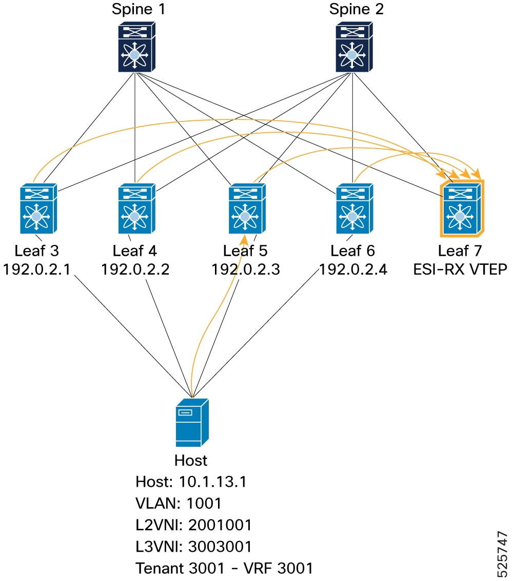
BGP: Leaf7# show bgp l2vpn evpn 10.1.13.1 Path type: internal, path is valid, not best reason: Router Id, multipath, no labeled nexthop, in rib Imported from 192.0.2.10:33768:[2]:[0]:[0]:[48]:[0010.0100.1301]:[32]:[10.1.13.1]/272 AS-Path: NONE, path sourced internal to AS 192.0.2.3 (metric 9) from 192.0.2.21 (192.0.2.21) Origin IGP, MED not set, localpref 100, weight 0 Received label 2001001 3003001 Extcommunity: RT:1:2001001 RT:1:3003001 SOO:192.0.2.10:256 ENCAP:8 Router MAC:4880.0290.01af Originator: 192.0.2.10 Cluster list: 192.0.2.21 ESI: 0300.0034.5634.5600.0001 Path type: internal, path is valid, not best reason: Router Id, multipath, no labeled nexthop, in rib Imported from 192.0.14.1:33768:[2]:[0]:[0]:[48]:[0010.0100.1301]:[32]:[10.1.13.1]/272 AS-Path: NONE, path sourced internal to AS 192.0.2.2 (metric 9) from 192.0.2.21 (192.0.2.21) Origin IGP, MED not set, localpref 100, weight 0 Received label 2001001 3003001 Extcommunity: RT:1:2001001 RT:1:3003001 SOO:192.0.14.1:256 ENCAP:8 Router MAC:f839.1867.df6b Originator: 192.0.14.1 Cluster list: 192.0.2.21 ESI: 0300.0034.5634.5600.0001 Advertised path-id 1 Path type: internal, path is valid, is best path, no labeled nexthop, in rib Imported from 192.0.13.1:33768:[2]:[0]:[0]:[48]:[0010.0100.1301]:[32]:[10.1.13.1]/272 AS-Path: NONE, path sourced internal to AS 192.0.2.1 (metric 9) from 192.0.2.21 (192.0.2.21) Origin IGP, MED not set, localpref 100, weight 0 Received label 2001001 3003001 Extcommunity: RT:1:2001001 RT:1:3003001 SOO:192.0.13.1:256 ENCAP:8 Router MAC:4880.0290.0727 Originator: 192.0.13.1 Cluster list: 192.0.2.21 ESI: 0300.0034.5634.5600.0001 Path type: internal, path is valid, not best reason: Router Id, multipath, no labeled nexthop, in rib Imported from 192.0.16.1:33768:[2]:[0]:[0]:[48]:[0010.0100.1301]:[32]:[10.1.13.1]/272 AS-Path: NONE, path sourced internal to AS 192.0.2.4 (metric 9) from 192.0.2.21 (192.0.2.21) Origin IGP, MED not set, localpref 100, weight 0 Received label 2001001 3003001 Extcommunity: RT:1:2001001 RT:1:3003001 ENCAP:8 Router MAC:f839.184d.48c7 Originator: 192.0.16.1 Cluster list: 192.0.2.21 ESI: 0300.0034.5634.5600.0001L2RIB: Leaf7# show l2route evpn mac-ip evi 1001 detail Topology Mac Address Host IP Prod Flags Seq No Next-Hops ----------- -------------- ------------------------------------ ------ ----------------- ---------- -------------------------- 1001 0010.0100.1301 10.1.13.1 BGP -- 0 192.0.2.1 (Label: 2001001) 192.0.2.2 (Label: 2001001) 192.0.2.3 (Label: 2001001) 192.0.2.4 (Label: 2001001) Sent To: ARP ESI : 0300.0034.5634.5600.0001 Encap-type:1L2FM Leaf7# show mac address-table vlan 1001 VLAN MAC Address Type age Secure NTFY Ports ---------+-----------------+--------+---------+------+----+------------------ C 1001 0010.0100.1301 dynamic NA F F nve1(192.0.2.1 192.0.2.2 192.0.2.3 192.0.2.4)URIB: Leaf7# show ip route 10.1.13.1 detail vrf 3001 10.1.13.1/32, ubest/mbest: 4/0 Extended Community: 0x1b 1c 01 03 65 01 0f 01 01 00 00 00 00 00 00 00 00 00 03 00 00 34 56 34 56 00 00 01 *via 192.0.2.1%default, [200/0], 1d00h, bgp-1, internal, tag 1, segid: 3003001 tunnelid: 0x66010d01 encap: VXLAN BGP-EVPN: VNI=3003001 (EVPN) client-specific data: 125 recursive next hop: 192.0.2.1/32%default extended route information: BGP origin AS 1 BGP peer AS 1 *via 192.0.2.2%default, [200/0], 1d00h, bgp-1, internal, tag 1, segid: 3003001 tunnelid: 0x66010e01 encap: VXLAN BGP-EVPN: VNI=3003001 (EVPN) client-specific data: 138 recursive next hop: 192.0.2.2/32%default extended route information: BGP origin AS 1 BGP peer AS 1 *via 192.0.2.3%default, [200/0], 1d00h, bgp-1, internal, tag 1, segid: 3003001 tunnelid: 0x66010f01 encap: VXLAN BGP-EVPN: VNI=3003001 (EVPN) client-specific data: 1e9 recursive next hop: 192.0.2.3/32%default extended route information: BGP origin AS 1 BGP peer AS 1 *via 192.0.2.4%default, [200/0], 1d00h, bgp-1, internal, tag 1, segid: 3003001 tunnelid: 0x66011001 encap: VXLAN BGP-EVPN: VNI=3003001 (EVPN) client-specific data: a2 recursive next hop: 192.0.2.4/32%default extended route information: BGP origin AS 1 BGP peer AS 1FIB: Leaf7# show forwarding ipv4 route 10.1.13.1 vrf 3001 ------------------+-----------------------------------------+----------------------+-----------------+----------------- Prefix | Next-hop | Interface | Labels | Partial Install ------------------+-----------------------------------------+----------------------+-----------------+----------------- 10.1.13.1/32 192.0.2.1 nve1 192.0.2.2 nve1 192.0.2.3 nve1 192.0.2.4 nve1
-
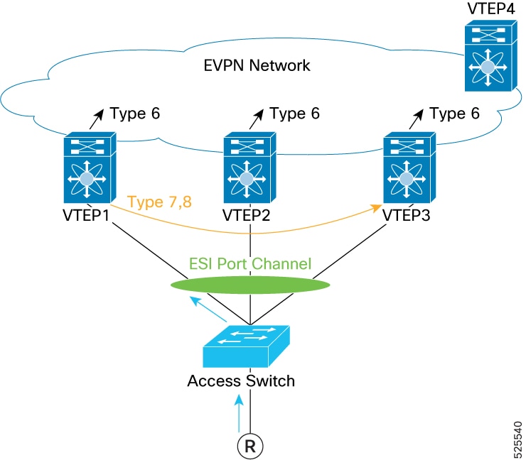
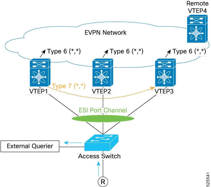
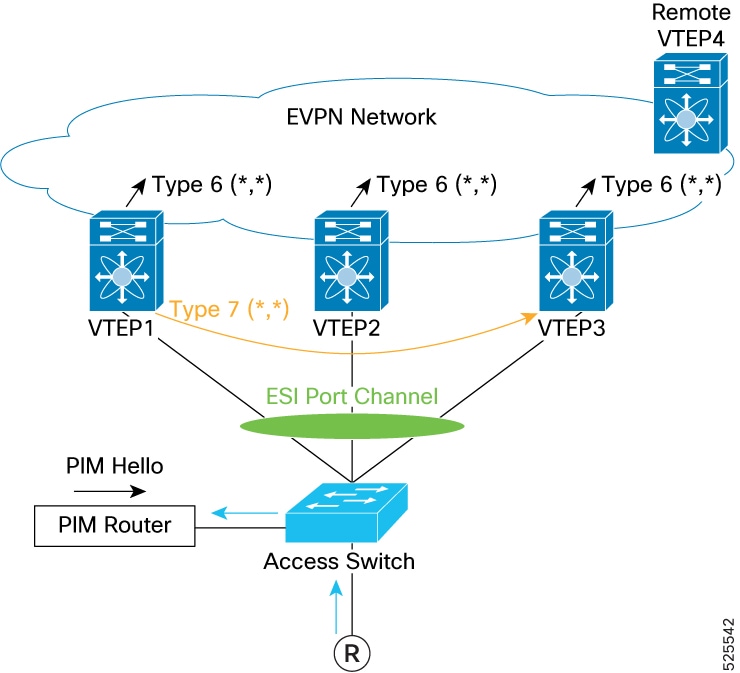
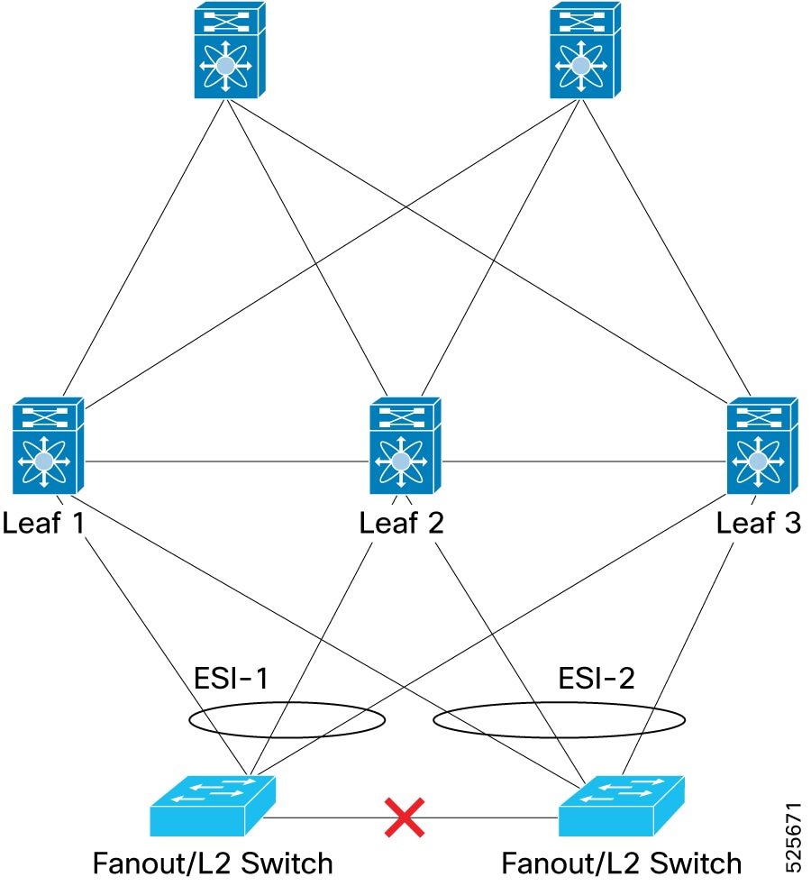
 Feedback